Motorola Solutions 99FT3081 CDM1550LS+ 220MHz Mobile Radio User Manual 6864110R13 O cvr
Motorola Solutions, Inc. CDM1550LS+ 220MHz Mobile Radio 6864110R13 O cvr
Contents
Ex 8 Users Manual
Motorola, The Stylized M logo, Intelligence Everywhere, Professional Radio - As Dedicated As You Are, CDM Series,
CDM1550•LS+, and Call Alert are trademarks of Motorola, Inc.
LTR is a mark of E.F. Johnson Company.
PassPort is a registered trademark of Trident Datacomm Technologies, Inc.
© 2002 Motorola, Inc. All rights reserved. Printed in U.S.A.
*6864110R13-O*
6864110R13-O
CDM1550••LS++User Guide
Professional Radio - As Dedicated As You Are™
6864110R13-O_cvr.qxd 4/15/2002 3:46 PM Page 1

1
English
CONTENTS
CONTENTS
Computer Software Copyrights . . . . . . . . . 6
Safety . . . . . . . . . . . . . . . . . . . . . . . . . . . . 7
User Safety, Training, and
General Information . . . . . . . . . . . . . . . . . . 7
Compliance with RF Energy Exposure
Standards. . . . . . . . . . . . . . . . . . . . . . . . . . 7
Operational Instructions and Training
Guidelines . . . . . . . . . . . . . . . . . . . . . . . . . 8
Transmit and Receive . . . . . . . . . . . . . . 8
Mobile Antennas . . . . . . . . . . . . . . . . . . 9
Approved Accessories . . . . . . . . . . . . . 9
Fixed Site Antennas . . . . . . . . . . . . . . . 9
Electromagnetic Interference/
Compatibility. . . . . . . . . . . . . . . . . . . . . . . 10
Facilities . . . . . . . . . . . . . . . . . . . . . . . 10
Vehicles . . . . . . . . . . . . . . . . . . . . . . . 10
Driver Safety . . . . . . . . . . . . . . . . . . . . 11
Operational Warnings . . . . . . . . . . . . . . . 11
For Vehicles With an Air Bag . . . . . . . 11
Potentially Explosive Atmospheres. . . 11
Blasting Caps and Areas . . . . . . . . . . 11
Introduction . . . . . . . . . . . . . . . . . . . . . . .13
Trunked Radio Systems . . . . . . . . . . . . . .13
PassPort® Trunked Systems . . . . . . . .13
LTR® Trunked Systems . . . . . . . . . . . .13
Conventional Radio Systems . . . . . . . . . .14
CDM1550•LS+™ Radio Features . . . . . . .14
Radio Wide Features . . . . . . . . . . . . . .14
PassPort Zone Features . . . . . . . . . . .14
LTR Zone Features . . . . . . . . . . . . . . .15
Conventional Zone Features . . . . . . . .15
Radio Overview . . . . . . . . . . . . . . . . . . . .17
Parts of the Radio . . . . . . . . . . . . . . . . . . .17
CDM1550•LS+ Model. . . . . . . . . . . . . .17
On/Off/Volume Control Knob . . . . . . . .18
LED Indicators . . . . . . . . . . . . . . . . . . .18
Push-to-Talk (PTT) Button . . . . . . . . . .19
Microphone. . . . . . . . . . . . . . . . . . . . . .19
Menu/Select Button ). . . . . . . . . . .19
Menu Exit/Button (. . . . . . . . . . . . .19
Menu Buttons . . . . . . . . . . . . . . . . . . . .19
Display . . . . . . . . . . . . . . . . . . . . . . . . .20
Microphone Jack . . . . . . . . . . . . . . . . .21
Optional DTMF Microphone (RMN4026). .21
DTMF Microphone Keypad . . . . . . . . .22
6864110R13-OTOC.fm Page 1 Monday, April 15, 2002 5:18 PM

2
English
CONTENTS
Programmable Buttons. . . . . . . . . . . . . . . 24
Audio Indicators for Programmable
Buttons . . . . . . . . . . . . . . . . . . . . . . . . 28
Getting Started . . . . . . . . . . . . . . . . . . . . 29
Turning the Radio On or Off . . . . . . . . . . . 29
Adjusting the Volume . . . . . . . . . . . . . . . . 29
Selecting a Trunked Zone
and Talkgroup. . . . . . . . . . . . . . . . . . . . . . 30
Sending a Trunked Call . . . . . . . . . . . . . . 30
Selecting a Conventional Zone
and Channel . . . . . . . . . . . . . . . . . . . . . . . 31
Direct Zone Access. . . . . . . . . . . . . . . . . . 31
Direct Channel Access . . . . . . . . . . . . . . . 31
Sending a Conventional Call . . . . . . . . . . 33
Receiving a Trunked or Conventional
Call . . . . . . . . . . . . . . . . . . . . . . . . . . . . . . 33
Repeater or Talkaround J Mode
(Conventional Operation Only) . . . . . . . . . 34
Call Light
(Trunked Operation Only). . . . . . . . . . . . . 35
Home Channel . . . . . . . . . . . . . . . . . . . . . 35
Horn and Lights . . . . . . . . . . . . . . . . . . . . 35
To Activate Horn and Lights
Programmed with Call Light
(Trunked Operation Only) . . . . . . . . . . 35
To Activate Horn and Lights
Programmed with Call Alert
(LTR Trunked and Conventional
Operation Only). . . . . . . . . . . . . . . . . . 36
Remote Monitor
(LTR Trunked and Conventional
Operation Only) . . . . . . . . . . . . . . . . . . . . 36
Passport Trunking . . . . . . . . . . . . . . . . . 39
Seamless Roaming . . . . . . . . . . . . . . . . . 39
Initial Registration . . . . . . . . . . . . . . . . 39
Roaming and Registering Between
Sites . . . . . . . . . . . . . . . . . . . . . . . . . . 40
Site/Min View . . . . . . . . . . . . . . . . . . . . . . 41
Roam Request . . . . . . . . . . . . . . . . . . . . . 42
To Start a Roam Request . . . . . . . . . 42
To Cancel a Roam Request . . . . . . . . 43
Troubleshooting . . . . . . . . . . . . . . . . . . . . 43
Radio Calls . . . . . . . . . . . . . . . . . . . . . . . 45
Making a Selective Call
(LTR Trunked and Conventional
Operation Only) . . . . . . . . . . . . . . . . . . . . 45
Receiving a Selective Call F
(LTR Trunked and Conventional
Operation Only) . . . . . . . . . . . . . . . . . . . . 46
6864110R13-OTOC.fm Page 2 Monday, April 15, 2002 5:18 PM

3
English
CONTENTS
Sending a Call Alert Page
(LTR Trunked and Conventional
Operation Only). . . . . . . . . . . . . . . . . . . . . 46
Receiving a Call Alert Page
(LTR Trunked and Conventional
Operation Only). . . . . . . . . . . . . . . . . . . . . 47
Radio Check
(LTR Trunked and Conventional
Operation Only). . . . . . . . . . . . . . . . . . . . . 48
Sending a Status
(Conventional Operation Only) . . . . . . . . . 48
Sending a Message
(Conventional Operation Only) . . . . . . . . . 49
Receiving a Message
(Conventional Operation Only) . . . . . . . . . 50
Responding to Emergency Alerts E
(Conventional Operation Only) . . . . . . . . . 50
Decoding an Emergency Alarm . . . . . . 51
Multiple Queued Emergencies. . . . . . . 52
Three Minute Timer . . . . . . . . . . . . . . . 52
After the Timer Expires . . . . . . . . . . . . 52
Clearing an Emergency Alert E
(Conventional Operation Only) . . . . . . . . . 53
Sending an Emergency Remote Monitor
(Conventional Operation Only) . . . . . . . . . 53
Sending an Emergency Alert E
(Conventional Operation Only) . . . . . . . . . 54
Sending a Remote Monitor . . . . . . . . . . . . 54
Selective Radio Inhibit
(LTR Trunked and Conventional
Operation Only) . . . . . . . . . . . . . . . . . . . . 55
Editing a Radio Call List K
(LTR Trunked and Conventional
Operation Only) . . . . . . . . . . . . . . . . . . . . 55
Name and Call Tone Tagging
(LTR Trunked and Conventional
Operation Only) . . . . . . . . . . . . . . . . . . . . 56
To Tag a Specific User’s Name. . . . . . 56
To Tag a Type of Radio Call . . . . . . . . 57
Scan. . . . . . . . . . . . . . . . . . . . . . . . . . . . . 59
Talkback . . . . . . . . . . . . . . . . . . . . . . . . . . 59
PassPort Primary Auto Group Scan
(PassPort Trunked Operation Only) . . . . . 60
PassPort Group Scan G
(PassPort Trunked Operation Only) . . . . . 60
Enabled . . . . . . . . . . . . . . . . . . . . . . . . 60
To Start or Stop PassPort Group
Scan Operation through a
Preprogrammed Button . . . . . . . . . . . . 61
To Start or stop PassPort Group
Scan Operation through the Menu . . . 61
Auto Group Scan
(LTR Trunked Operation Only). . . . . . . . . 61
To Start Auto Group Scan . . . . . . . . . . 61
To Stop Auto Group Scan . . . . . . . . . . 62
6864110R13-OTOC.fm Page 3 Monday, April 15, 2002 5:18 PM

4
English
CONTENTS
All Group Scan
(LTR Trunked Operation Only) . . . . . . . . . 62
To Start or Stop All Group Scan
Operation through a Preprogrammed
Button . . . . . . . . . . . . . . . . . . . . . . . . . 62
To Start or Stop All Group Scan
Operation Through the Menu . . . . . . . 62
System Scan G
(LTR Trunked and Conventional
Operation Only) . . . . . . . . . . . . . . . . . . . . 63
When System Scan is Enabled . . . . . . 63
To Start or Stop a System Scan
Operation. . . . . . . . . . . . . . . . . . . . . . . 63
Deleting a Nuisance Channel/Talkgroup
(PassPort Group Scan or System Scan
Operation Only) . . . . . . . . . . . . . . . . . . . . 64
To Temporarily Delete the
Channel/Talkgroup . . . . . . . . . . . . . . . 64
Restoring a Channel/Talkgroup Back
to the Scan List . . . . . . . . . . . . . . . . . . 64
Editing a Scan List
(PassPort Group Scan or System Scan
Operation Only) . . . . . . . . . . . . . . . . . . . . 64
Adding or Deleting Talkgroups or
Channels in a Scan List . . . . . . . . . . . . . . 65
Prioritizing a Talkgroup or Channel
in a Scan List
(System Scan Operation Only) . . . . . . . . 66
Phone . . . . . . . . . . . . . . . . . . . . . . . . . . . 69
Making a Phone Call D Through a
Trunked System. . . . . . . . . . . . . . . . . . . . 69
Making a Phone Call D Through a
Conventional System . . . . . . . . . . . . . . . . 70
Receiving a Phone Call D Through a
Trunked or Conventional System. . . . . . . 72
Modifying the Phone List K . . . . . . . . . . 73
To Add an Entry . . . . . . . . . . . . . . . . . 73
To Delete an Entry . . . . . . . . . . . . . . . 74
To Edit an Entry . . . . . . . . . . . . . . . . . 75
Voice Storage . . . . . . . . . . . . . . . . . . . . . 77
Incoming Call Recording . . . . . . . . . . . . . 78
Selective Incoming Call Recording . . . 78
To Selectively Record an Incoming
Call . . . . . . . . . . . . . . . . . . . . . . . . . . . 78
All Incoming Call Recording . . . . . . . . 78
To Record All Incoming Calls . . . . . . . 79
Voice Memo Recording . . . . . . . . . . . . . . 80
To Record a Voice Memo using the
Preprogrammed Record/Playback
Button . . . . . . . . . . . . . . . . . . . . . . . . . 80
6864110R13-OTOC.fm Page 4 Monday, April 15, 2002 5:18 PM

5
English
CONTENTS
To Record a Voice Memo using the
Menu . . . . . . . . . . . . . . . . . . . . . . . . . . 80
Recorded Message Playback . . . . . . . . . . 81
To Playback a Message using the Prepro-
grammed Record/Playback Button . . . 81
To Playback a Message using the
Menu . . . . . . . . . . . . . . . . . . . . . . . . . . 82
Recorded Message Delete . . . . . . . . . . . . 82
To Delete a Message using the
Preprogrammed Delete Playback
Button . . . . . . . . . . . . . . . . . . . . . . . . . 82
To Delete a Message using the
Menu . . . . . . . . . . . . . . . . . . . . . . . . . . 83
Recorded Message Transmission . . . . . . 83
Answer Mode . . . . . . . . . . . . . . . . . . . . . . 84
To Enable the Answer Mode Feature . 84
To Record a Message . . . . . . . . . . . . . 84
To Disable the Answer Mode Feature . 85
Audio/Tone Settings . . . . . . . . . . . . . . . . 87
Utilities . . . . . . . . . . . . . . . . . . . . . . . . . . . 89
Setting the Power Level B. . . . . . . . . . . . 91
Setting the Clock/Alarm. . . . . . . . . . . . . . . 92
Displaying the Time. . . . . . . . . . . . . . . . . . 93
Selecting the Display Language
(LTR Trunked and Conventional
Operation Only) . . . . . . . . . . . . . . . . . . . . 93
Warranty . . . . . . . . . . . . . . . . . . . . . . . . . 95
Accessories . . . . . . . . . . . . . . . . . . . . . . 99
Microphones. . . . . . . . . . . . . . . . . . . . . . . 99
Handsfree Kits . . . . . . . . . . . . . . . . . . . . . 99
Exchangeable Button Kits . . . . . . . . . . . . 99
Mounting Kits . . . . . . . . . . . . . . . . . . . . . . 99
Remote Mounts . . . . . . . . . . . . . . . . . . . 100
External Speakers . . . . . . . . . . . . . . . . . 100
Installation and Alarm Kits . . . . . . . . . . . 100
Antennas . . . . . . . . . . . . . . . . . . . . . . . . 100
Service Aids and Programming
Equipment Manuals . . . . . . . . . . . . . . . . 100
Manuals . . . . . . . . . . . . . . . . . . . . . . . . . 101
Control Station Kits. . . . . . . . . . . . . . . . . 101
Mobile Data Units Section . . . . . . . . . . . 101
Public Address . . . . . . . . . . . . . . . . . . . . 103
Retrofit Kit. . . . . . . . . . . . . . . . . . . . . . . . 103
6864110R13-OTOC.fm Page 5 Monday, April 15, 2002 5:18 PM

6
English
CONTENTS
COMPUTER SOFTWARE
COPYRIGHTS
The Motorola products described in this
manual may include copyrighted Motorola
computer programs stored in semiconductor
memories or other media. Laws in the United
States and other countries preserve for
Motorola certain exclusive rights for
copyrighted computer programs, including, but
not limited to, the exclusive right to copy or
reproduce in any form the copyrighted
computer program. Accordingly, any
copyrighted Motorola computer programs
contained in the Motorola products described
in this manual may not be copied, reproduced,
modified, reverse-engineered, or distributed in
any manner without the express written
permission of Motorola. Furthermore, the
purchase of Motorola products shall not be
deemed to grant either directly or by
implication, estoppel, or otherwise, any license
under the copyrights, patents or patent
applications of Motorola, except for the normal
non-exclusive license to use that arises by
operation of law in the sale of a product.
6864110R13-OTOC.fm Page 6 Monday, April 15, 2002 5:18 PM

7
English
SAFETY
SAFETY
USER SAFETY, TRAINING, AND
GENERAL INFORMATION
READ THIS IMPORTANT INFORMATION ON
SAFE AND EFFICIENT OPERATION
BEFORE INSTALLING AND USING YOUR
MOTOROLA MOBILE TWO-WAY RADIO IN A
VEHICLE OR AS A CONTROL STATION.
COMPLIANCE WITH RF ENERGY
EXPOSURE STANDARDS
Your Motorola two-way radio is designed and
tested to comply with a number of national and
international standards and guidelines (listed
below) regarding human exposure to radio
frequency electromagnetic energy. This radio
complies with the IEEE (FCC) and ICNIRP
exposure limits at duty cycles of up to 50%
talk-50% listen and should be used for
occupational use only. In terms of measuring
RF energy for compliance with the FCC
exposure guidelines, your radio radiates
measurable RF energy only while it is
transmitting (during talking), not when it is
receiving (listening) or in standby mode.
Your Motorola two-way radio complies with the
following RF energy exposure standards and
guidelines:
• United States Federal Communications
Commission, Code of Federal Regulations;
47CFR part 2 sub-part J
• American National Standards Institute
(ANSI) / Institute of Electrical and Electronic
Engineers (IEEE) C95. 1- 1992
• Institute of Electrical and Electronic
Engineers (IEEE) C95.1- 1999 Edition
• International Commission on Non-Ionizing
Radiation Protection (ICNIRP) 1998
• Ministry of Health (Canada) Safety Code 6.
Limits of Human Exposure to Radiofrequency
Electromagnetic Fields in the Frequency
Range from 3 kHz to 300 GHz, 1999
• Australian Communications Authority
Radiocommunications (Electromagnetic
Radiation - Human Exposure) Standard
2001
• ANATEL, Brasil Regulatory Authority,
Resolution 256 (April 11, 2001) “additional
requirements for SMR, cellular and PCS
product certification.”
01_Safety.fm Page 7 Friday, May 3, 2002 11:38 AM

8
English
SAFETY
OPERATIONAL INSTRUCTIONS
AND TRAINING GUIDELINES
To ensure optimal performance and
compliance with the RF energy exposure
limits in the above standards and
guidelines, users should transmit no more
than 50% of the time and always adhere to
the following procedures:
Transmit and Receive
• To transmit (talk), push the Push-To-Talk
(PTT) button; to receive, release the PTT
button.
•Transmit only when people outside the
vehicle are at least the minimum lateral
distance away, as shown in Table 1, from
a properly installed, externally-mounted
antenna.
Table 1 lists the minimum lateral distance
for bystanders in an uncontrolled
environment from the transmitting antenna
at several different ranges of rated radio
power for mobile radios installed in a
vehicle.
Mobile Antennas
•Install antennas at the center of the roof
or the center of the trunk deck. These
mobile antenna installation guidelines
are limited to metal body vehicles.
•The antenna installation must addition-
ally be in accordance with:
a. The requirements of the antenna manu-
facturer/supplier
b. Instructions in the Radio Installation
Manual
Table 1: Rated Power and Lateral Distance
Rated Power of
Vehicle-installed
Mobile Two-way Radio
Minimum Lateral
Distance from
Transmitting Antenna
Less than 7 watts 8 inches
(20 centimeters)
7 to 15 watts 1 foot
(30 centimeters)
16 to 50 watts 2 feet
(60 centimeters)
51 to 110 watts 3 feet
(90 centimeters)
01_Safety.fm Page 8 Friday, May 3, 2002 11:38 AM

9
English
SAFETY
•Use only Motorola approved supplied
antenna or Motorola approved replace-
ment antenna. Unauthorized antennas,
modifications, or attachments could dam-
age the radio and may violate FCC regula-
tions.
Approved Accessories
For a list of Motorola approved antennas see
the Accessory section of this user manual.
Fixed Site Antennas
If mobile radio equipment is installed at a fixed
location and operated as a control station or as
a fixed unit, the antenna installation must
comply with the following requirements in order
to ensure optimal performance and compliance
with the RF energy exposure limits in the
above standards and guidelines.
• The antenna should be mounted outside
the building on the roof or a tower if at all
possible.
• As with all fixed site antenna installations, it
is the responsibility of the licensee to man-
age the site in accordance with applicable
regulatory requirements and may require
additional compliance actions such as site
survey measurements, signage, and site
access restrictions in order to insure that
exposure limits are not exceeded.
ELECTROMAGNETIC
INTERFERENCE/COMPATIBILITY
NOTE: Nearly every electronic device is sus-
ceptible to electromagnetic interfer-
ence (EMI) if inadequately shielded,
designed or otherwise configured for
electromagnetic compatibility. It may be
necessary to conduct compatibility
testing to determine if any electronic
equipment used in or around vehicles
or near fixed antenna sites is sensitive
to external RF energy and if any proce-
dures need to be followed to eliminate
or mitigate the potential for interaction
between the radio transmitter and the
equipment or device.
01_Safety.fm Page 9 Friday, May 3, 2002 11:38 AM

10
English
SAFETY
Facilities
To avoid electromagnetic interference and/or
compatibility conflicts, turn off your radio in
any facility where posted notices instruct
you to do so. Hospitals or health care facilities
may be using equipment that is sensitive to
external RF energy.
Vehicles
To avoid possible interaction between the radio
transmitter and any vehicle electronic control
modules, for example, ABS, engine, or
transmission controls, we recommend that the
radio be installed by an experienced installer
and that the following precautions be used
when installing the radio:
1. Refer to any manufacturers instructions
or other technical bulletins or
recommendations on radio installation.
2. Before installing the radio, determine
the location of the electronic control
modules and their harnesses in the
vehicle.
3. Route all radio wiring, including the
antenna transmission line, as far away
as possible from the electronic control
units and associated wiring.
Driver Safety
Check the laws and regulations on the use of
radios in the area where you drive. Always
obey them.
When using your radio while driving, please:
• Give full attention to driving and to the
road.
• Pull off the road and park before making
or answering a call if driving conditions
so require.
OPERATIONAL WARNINGS
For Vehicles With an Air Bag
Do not place a mobile radio in the area over an
air bag or in the air bag deployment area. Air
bags inflate with great force. If a radio is placed
!
W A R N I N G
!
01_Safety.fm Page 10 Friday, May 3, 2002 11:38 AM

11
English
SAFETY
in the air bag deployment area and the air bag
inflates, the radio may be propelled with great
force and cause serious injury to occupants of
the vehicle.
Potentially Explosive Atmospheres
Turn off your radio prior to entering any area
with a potentially explosive atmosphere.
Sparks in a potentially explosive atmosphere
can cause an explosion or fire resulting in
bodily injury or even death.
The areas with potentially explosive
atmospheres referred to above include fueling
areas such as below decks on boats, fuel or
chemical transfer or storage facilities, areas
where the air contains chemicals or particles,
such as grain, dust or metal powders, and any
other area where you would normally be
advised to turn off your vehicle engine. Areas
with potentially explosive atmospheres are
often but not always posted.
Blasting Caps and Areas
To avoid possible interference with blasting
operations, turn off your radio when you are
near electrical blasting caps, in a blasting area,
or in areas posted: “Turn off two-way radio.”
Obey all signs and instructions.
For radios installed in vehicles fuelled by
liquefied petroleum gas, refer to the (U.S.)
National Fire Protection Association standard,
NFPA 58, for storage, handling, and/ or
container information. For a copy of the LP-
gas standard, NFPA 58, contact the National
Fire Protection Association, One Battery Park,
Quincy, MA.
01_Safety.fm Page 11 Friday, May 3, 2002 11:38 AM

12
English
SAFETY
01_Safety.fm Page 12 Friday, May 3, 2002 11:38 AM

13
English
INTRODUCTION
INTRODUCTION
Welcome to Motorola’s
CDM Series family of
radio users. The
CDM1550•LS+™, the
Intelligent Radio,
combines the very latest
in two-way technology
while delivering
outstanding functionality at the touch of a
button.
The CDM1550•LS+ mobile radio operates on
PassPort and LTR trunked and conventional
radio systems.
TRUNKED RADIO SYSTEMS
Trunked systems allow a large number of users
to share a relatively small number of
frequencies or repeaters without interfering
with each other. The airtime of all the repeaters
in a trunked system is pooled, which
maximizes the amount of airtime available to
any one radio and minimizes channel
congestion.
PassPort® Trunked Systems
PassPort is an enhanced trunking protocol
developed by Trident Micro Systems that
supports wide area dispatch networking. A
network is formed by linking several trunked
sites together to form a single system. This
offers users an extended communication
coverage area. Additionally, users with
PassPort can seamlessly roam among all sites
within the network. Seamless roaming means
that the radio user does not have to manually
change the zones on the radio when roaming
from site-to-site.
LTR® Trunked Systems
LTR is a transmission based trunking protocol
developed by the E. F. Johnson Company for
primarily single site trunking applications. In
transmission trunking, a repeater is used for
only the duration of a single transmission.
Once a transmission is completed, that
repeater becomes available to other users.
This means that a conversation comprised of
many transmissions may occur over several
different channels within the LTR system. This
method of trunking provides system efficiency

14
English
INTRODUCTION
by making repeaters available to all users after
every transmission.
CONVENTIONAL RADIO SYSTEMS
Conventional radio systems typically refers to
unit-to-unit communications through a single
channel. Conventional systems also allow
radio users to extend communication coverage
by relaying their messages through a repeater.
To ensure coordinated use by multiple
talkgroups, each radio user must monitor the
channel or repeater before transmitting to
verify that the system is not currently busy.
CDM1550•LS+ RADIO FEATURES
CDM1550•LS+ Radio Feature Highlights:
Radio Wide Features
• 14-Character Alphanumeric Display
• 4 Programmable Feature Buttons
• Up to 15 PassPort and/or LTR Zones with
up to 16 Talkgroups per Zone
• Up to 16 Conventional Channels
• X-Pand Audio Enhancement Selectable by
Conventional Channel, LTR Repeater or
PassPort Talkgroup
• Home Channel
• Telephone Interconnect
• User-programmable Phone and Scan Lists
• Voice Storage Capability
PassPort Zone Features
• Unique Mobile Identity Number per Radio
• Unique Electronic Serial Number per
Radio
• Registration/Deregistration upon power up/
power down
• Automatic Seamless Roaming between
Networked Sites
• Registered Site and Mobile Identity View
• User Initiated Roam Request
• PassPort Primary Group Auto Scan and
PassPort Scan
Note: Throughout this manual there are
features listed as trunked and con-
ventional. Trunked indicates the fea-
ture functions in both PassPort and
LTR zones unless otherwise noted.
Conventional indicates the feature
functions in Conventional zones
only.

15
English
INTRODUCTION
PassPort Zone Features (Cont.)
• Call Signalling Features
LTR Zone Features
• MDC 1200 Signaling
• Auto Group System, All Group Scan
• System Scan with 2 Priority Levels
Conventional Zone Features
• Monitor and Sticky Permanent Monitor
• System Scan with 2 Priority Levels
- PTT ID (Display of Mobile
Identification Number)
- Call Alert
- Selective Call - Radio Check
- Caller ID

16
English
INTRODUCTION
Notes
17
English
RADIO OVERVIEW
RADIO OVERVIEW
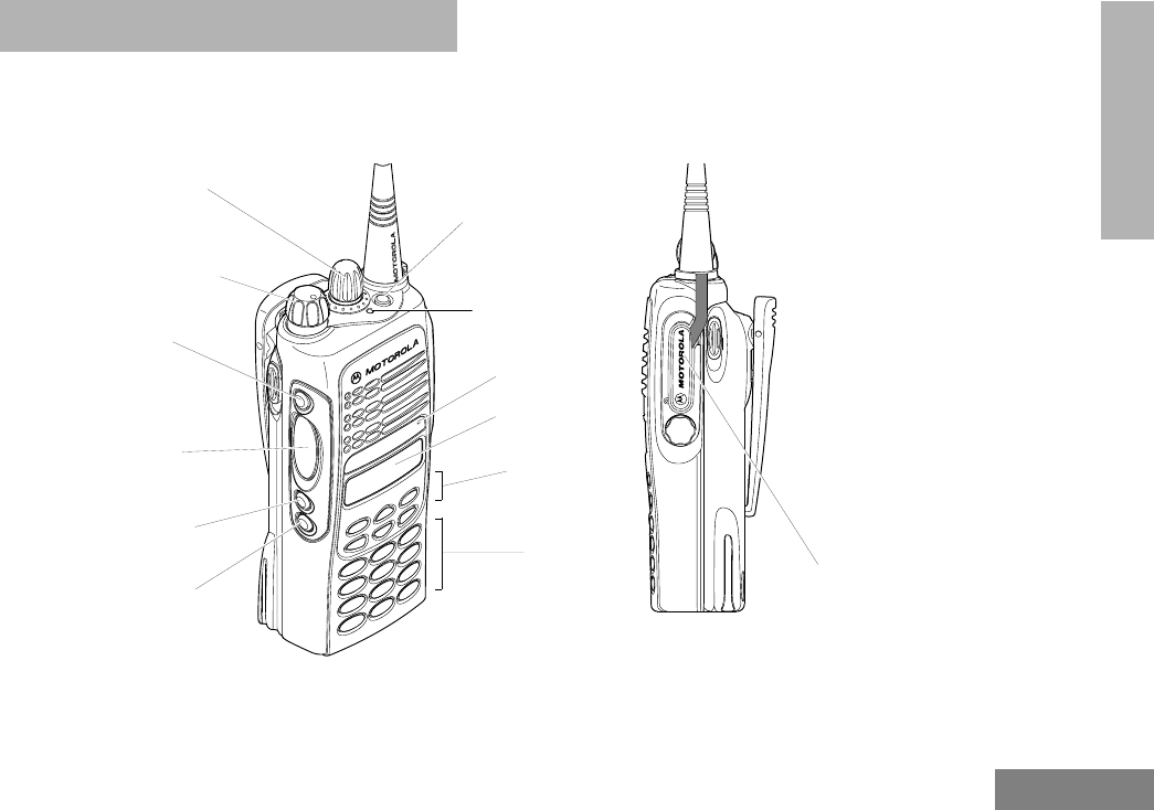
PARTS OF THE RADIO
HT1250•LS+ Model
On/Off/Volume Knob
Display
Microphone
Keypad
Menu Keys
(programmable)
Side Button 1 (A)
Push-to-Talk (PTT)
(programmable)
Side Button 2 (B)
(programmable)
Side Button 3 (C)
Zone Selector Knob
(programmable)
Top Button (D)
Button
(P1, P2, P3)
(programmable)
LED Indicator
Side
Connector
Cover
03_Radio Overview.fm Page 17 Monday, April 15, 2002 5:26 PM

18
English
RADIO OVERVIEW
On/Off/Volume Knob
Turns the radio on or off, and adjusts the
radio’s volume.
Zone Selector Knob
Switches the radio to different trunked and
conventional zones. It is also used to scroll
through menu choices when in Menu Mode.
LED Indicator
Indicates battery status (see page 30); or the
status of power-up, scan, or receipt of a
talkgroup or selective call (see table below):
Push-to-Talk (PTT) Button
Press and hold down this button to talk;
release it to listen.
Microphone
When sending a message, hold the
microphone 1 to 2 inches (2.5 to 5 cm) away
from your mouth, and speak clearly into the
microphone.
Menu Keys
LED Color Indicates
Steady red Radio is transmitting (PTT button
pressed)
Flashing red Radio is attempting to access
trunked system (PTT button
pressed), or
Radio is receiving (PTT button
released)
Double
flashing yellow Call Light feature, or
Individual Selective Call
Received (trunked operation only)
Single flashing
yellow Group Selective call received
(trunked operation only)
Momentary
green Radio has powered-up
successfully
Double
flashing green System or All Group Scan
operation, PassPort Group Scan
(+ u
<?>
LED Color Indicates
Exit Up Menu/Select
Left Down Right
03_Radio Overview.fm Page 18 Monday, April 15, 2002 5:26 PM

19
English
RADIO OVERVIEW
Menu/Select Key )
Used to enter menu mode. When in menu mode,
this key is also used to make menu selections.
Exit Key (
Used to move to the previous menu level (short
press) or to exit menu mode (long press).
Up Key + and Down Key ?
• Used to scroll through the preprogrammed
talkgroups of a selected trunked zone, or
through conventional channels when in
conventional zone.
• Used for scrolling when in menu mode.
•The ? key can also be programmed with
a radio feature (see page 22).
Right Key >
Moves the cursor right or inserts a space when
editing call, scan, and phone lists. This key can
also be programmed with a radio feature (see
page 22).
Left Key <
Used as a backspace key when editing radio
call, scan, and phone lists. This key can also
be programmed with a radio feature (see
page 22).
Keypad Keys
These keys are used for:
• Dialing a phone number
• Entering a specific radio ID number when
making a selective call or call alert
• Entering information when programming
radio call, scan, and phone lists
Each key can generate several different
characters. For example, to enter the character
“C,” press the 2 key three times. (Refer to the
following table.)
123
456
789
*0#
03_Radio Overview.fm Page 19 Monday, April 15, 2002 5:26 PM

20
English
RADIO OVERVIEW
Entering Characters Using the Keypad
Number of Times Key is Pressed
Key 1234567891011 12 13 14 15
00()<>
11&%# *
2ABC2abc2ÁÇàáç
3DEF3def3ÈÉÊèéê
4GHI4gh i4Íìí
5JKL5 jkl5
6MNO6mno6ÑÓÔòóôö
7PQRS7pqrs7
8TUV8 tuv8Úùú
9WXYZ9wxyz9Yy
**/+-=
##Blank
Space -.!?’”,;:
´
´
03_Radio Overview.fm Page 20 Monday, April 15, 2002 5:26 PM
21
English
RADIO OVERVIEW
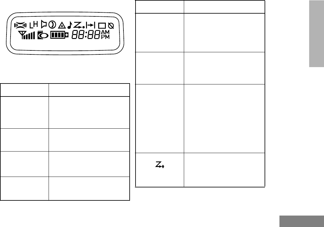
Display
The top two screen rows display menu and
radio status information:
Symbol Indication
A
X-Pand
The X-Pand feature is
activated. When in narrow
band, this feature improves
audio quality.
B
Power Level
Low Power “ R ” or High
Power “ S ” is activated.
C
Monitor
The selected channel is being
monitored (conventional
operation only).
D
Phone
Phone mode is selected.
Call Received
E
Emergency
An Emergency Siren is being
sounded. (Trunked mode only.)
An Emergency Alarm is being
send (Conventional mode
only).
F
Call Received
A Selective Call or Call Alert
has been received (LTR
trunked and Conventional
operation only).
G
Scan
When the green LED is
blinking, indicates that the
System, PassPort Scan, or All
Group Scan feature has been
activated.
When the green LED is off,
indicates that non-prioritized
Auto Group Scan has been
activated.
•Priority 1 Scan
(flashing)
Indicates activity on a priority
1 talkgroup or channel during
System Scan.
Symbol Indication
•
03_Radio Overview.fm Page 21 Monday, April 15, 2002 5:26 PM

22
English
RADIO OVERVIEW
Programmable Buttons
Several of your radio’s buttons can be
programmed by your dealer as shortcuts to
many of the radio’s features.
Programmable buttons include:
• The Three Side Buttons (A, B, C) and the
Top Button (D)
• The Three Lower Menu Keys (P1, P2, P3)
(when the radio is not in menu mode)
Each button can access up to two features,
depending on the type of button press:
H
Priority 2 Scan
( steady)
• When the green LED is on,
indicates activity on a
priority 2 talkgroup or
channel during System
Scan.
• When the green LED is off,
indicates prioritized Auto
Group Scan has been
activated.
J
Talkaround
You are not transmitting
through a repeater
(Conventional operation
only).
K
Programming
Mode
A Program list is being edited.
L
Keypad Lock
Keypad is locked.
P
Battery Level
The number of bars (0–4)
shown indicates the charge
remaining in your battery.
Symbol Indication
•
U
Clock
Shows the time (12- or
24-hour).
M
Signal Strength
The more bars, the stronger
the signal being received by
your radio.
N
PassPort Zone
A PassPort zone has been
selected.
Symbol Indication
03_Radio Overview.fm Page 22 Monday, April 15, 2002 5:26 PM

23
English
RADIO OVERVIEW
•Short Press—quickly pressing and
releasing the programmable buttons,
or
•Long Press—pressing and holding the
programmable buttons for a period of time
(programmable for 1/2 to 1 1/2 seconds),
or
•Hold Down—pressing and holding down
the programmable buttons while checking
status or making adjustments.
The table on page 24 summarizes the
programmable features available and shows
the page number where the feature is
explained.
In the “Button” column, have your dealer write
down the programmable buttons next to the
features that have been programmed to them.
Use the abbreviations (for example, A for Side
Button 1, D for Top Button, etc.) shown in the
radio illustration at the front of this manual.
Also, where a choice exists, have your dealer
indicate whether the button press is short
press (SP) or long press (LP).
Check with your dealer for a complete list of
features your radio supports.
03_Radio Overview.fm Page 23 Monday, April 15, 2002 5:26 PM

24
English
RADIO OVERVIEW
Programmable Features
Feature Indicator Short Press Long Press Hold Down Page Button
Battery Gauge LED
Color — — Check the battery’s
charge status. 30
Emergency
(Top button
only)
E
Initiate
Emergency Siren
(Trunked mode
only).
Initiate
Emergency Alarm
(Conventional
mode only).
Cancel Emergency
Siren Trunked
mode only).
Cancel Emergency
Alarm (Conven-
tional mode only).
—39
50
Home Channel
Revert —Directly access your favorite trunked
zone and talkgroup or conventional chan-
nel.†
—39
Keypad Lock L
— Toggle keypad
between locked and
unlocked.
——
Light — Turn on your radio backlight.†——
Monitor §CExit permanent
monitor mode. Enter permanent
monitor mode. Continually monitor
channel —
Phone DDirectly access Phone mode.†—66
† This feature is activated by EITHER a short OR a long press, but not both.
§ Conventional operation only. ‡LTR trunked operation only. *PassPort trunked operation only.
03_Radio Overview.fm Page 24 Monday, April 15, 2002 5:26 PM

25
English
RADIO OVERVIEW
Power Level BToggle transmit power level between high
and low.† —88
Radio Call ठLED
Color Directly access radio call menu.†—47
Repeater/
Talkaround §J
Toggle between using a conventional
repeater or transmitting directly to
another radio.†
—38
Roam Request*Searching Manually initiate
PassPort roaming
function.†
Stop PassPort
roaming function. — 43
Scan/Delete
Nuisance
Channel
G
Turn PassPort
Group, All Group,
and System scan
on or off.
Delete a nuisance
channel while
scanning. —60
Site/MIN View*—
Display the PassPort site number on
which the unit is registered, the Home
Site and unit’s MIN (Mobile Identity Num-
ber).†
—43
Speed Dial —Quickly access speed dial phone list.†—67
† This feature is activated by EITHER a short OR a long press, but not both.
§ Conventional operation only. ‡ LTR trunked operation only. *PassPort trunked operation only.
Programmable Features (Cont.)
Feature Indicator Short Press Long Press Hold Down Page Button
03_Radio Overview.fm Page 25 Monday, April 15, 2002 5:26 PM

26
English
RADIO OVERVIEW
Squelch §—Toggle squelch level between tight and
normal.†—88
Voice Storage
Record/Playback —Playback recorded
messages. Record voice
memos. —77
Voice Storage
Playback Exit —Exit Voice Storage Play Back mode.†—77
Voice Storage
Playback Delete —Delete recorded messages.†—78
Volume Set ———
Sound a tone for
adjusting your
radio’s volume level. 35
Edit Scan List —Add, Delete, or prioritize talkgroups or
channels. 60
† This feature is activated by EITHER a short OR a long press, but not both.
§ Conventional operation only. ‡ LTR trunked operation only. *PassPort trunked operation only.
Programmable Features (Cont.)
Feature Indicator Short Press Long Press Hold Down Page Button
03_Radio Overview.fm Page 26 Monday, April 15, 2002 5:26 PM
27
English
RADIO OVERVIEW
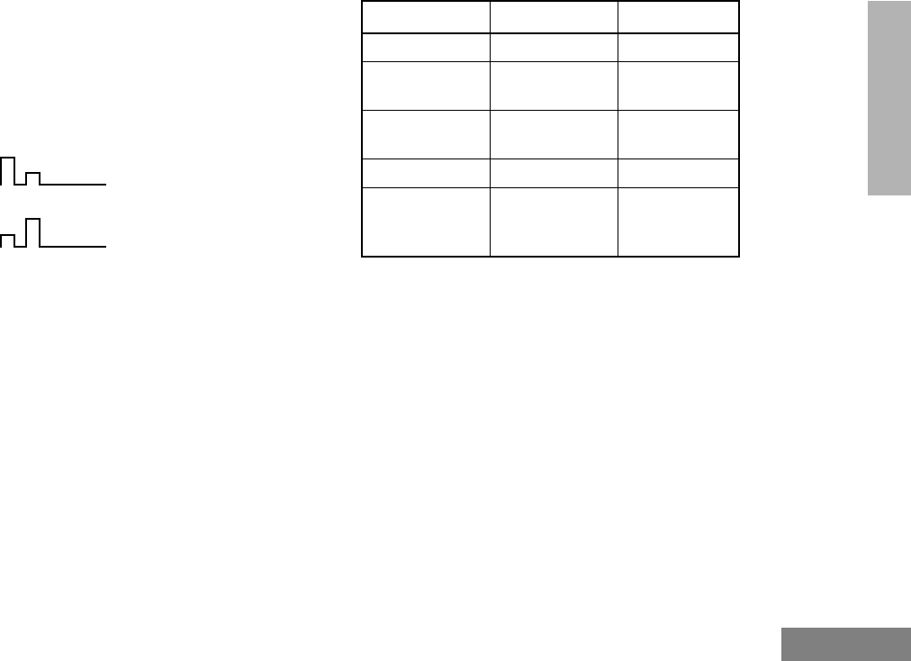
AUDIO INDICATORS FOR
PROGRAMMABLE BUTTONS
In addition to having visual indicators, some
programmable buttons use tones to indicate
one of two modes:
High-Low Tone
Low-High Tone
Button High-Low Tone Low-High Tone
Scan Stop scan Start scan
Power Level High power
selected Low power
selected
Squelch (no
visual indicator) Normal squelch Tight squelch
Keypad Lock Unlocked Locked
Repeater/
Talkaround
Uses
conventional
repeater
Does not use
conventional
repeater
03_Radio Overview.fm Page 27 Monday, April 15, 2002 5:26 PM

28
English
RADIO OVERVIEW
Notes
03_Radio Overview.fm Page 28 Monday, April 15, 2002 5:26 PM

29
English
GETTING STARTED
GETTING STARTED
TURNING THE RADIO ON OR OFF
ADJUSTING THE VOLUME
Turn the On/Off/Volume Control knob
clockwise to increase the volume, or
counterclockwise to decrease the volume.
–or–
ON OFF
Push the On/Off/
Volume Control knob.
If power-up is
successful, you hear
the Self-Test Pass Tone
and see the LED
momentarily turn
green.
If the radio fails to
power up, you hear the
Self-Test Fail
Tone .
Push the On/Off/
Volume Control knob
until you hear a click and
the display clears.
1Hold down the Volume Set button (see
page 26). You hear a continuous tone.
2Turn the On/Off/Volume Control knob to
the desired volume level.
3Release the Volume Set button.
Control Knob
On/Off/Volume
04_GetStarted.fm Page 29 Monday, April 15, 2002 4:17 PM

30
English
GETTING STARTED
SELECTING A TRUNKED ZONE
AND TALKGROUP
Up to 15 PassPort and/or LTR trunked zones
(containing 16 talkgroups each) can be
programmed into your radio.
To select a trunked zone and talkgroup:
SENDING A TRUNKED CALL
To Send a Trunked Call
Note: Throughout this manual there are
features listed as trunked and con-
ventional. Trunked indicates the fea-
ture functions in both PassPort and
LTR zones unless otherwise noted.
Conventional indicates the feature
functions in Conventional zones
only.
1v or w to select the appropriate
trunked zone.
2y or z until you see the desired
preprogrammed talkgroup on the display.
Note: N (the PassPort Zone symbol)
appears when a PassPort Zone has
been selected.
1Hold the microphone in a vertical position
at a distance of about 1 to 2 inches (2.5
to 5 cm) from your mouth.
2Press and hold the PTT button.
–or–
Press and release the PTT button and
wait 3 seconds.
• If access to the trunked system was
successful, the red LED indicator
lights steady.
- In addition, your dealer can
program your radio to sound a
short, high-pitched (talk permit)
tone, indicating successful trunked
system access.
• If access to the trunked system was
unsuccessful, the red LED indicator
flashes and a low-pitched (talk
prohibit) tone sounds, indicating that
the system was busy or out-of-range.
04_GetStarted.fm Page 30 Monday, April 15, 2002 4:17 PM

31
English
GETTING STARTED
SELECTING A CONVENTIONAL
ZONE AND CHANNEL
Up to a total of 16 conventional channels, in
one or more conventional zones, can be
programmed into your radio.
To Select a Conventional Zone and Channel
DIRECT ZONE ACCESS
The Direct Zone Access feature offers an
alternative way of accessing a trunked or
conventional zone.
To Activate Direct Zone Access
DIRECT CHANNEL ACCESS
The direct channel access feature allows you
to directly access a specific trunked talkgroup
or conventional channel within the zone you
have currently selected. This feature can be
programmed on one of the radio
programmable buttons (P1, P2, P3 or P4) and/
or any DTMF microphone (RMN4026)
programmable buttons (A, B or C).
3With the PTT button depressed, speak
clearly into the microphone
4Release the PTT button to listen.
1v or w to select the appropriate
conventional zone.
2y or z until you see the desired
conventional channel on the display.
1Press the preprogrammed Direct Zone
Access button (see page 26).
2y or z until you see the desired
zone on the display.
3u to confirm your selection.
04_GetStarted.fm Page 31 Monday, April 15, 2002 4:17 PM

32
English
GETTING STARTED
To Start Activate Direct Channel Access
Using the radio’s programmable buttons:
Using the DTMF microphone:
1Press the preprogrammed Direct
Channel button.
The current talkgroup or channel flashes
intermittently.
2Up or down arrow y or z to select
the appropriate Trunked talkgroup or
channel.
3Press again the preprogrammed Direct
Channel button.
–or–
Press y or z
The new selected talkgroup or channel
appears on the display
YR TKGP ALIAS
NW TKGP ALIAS
1Press the preprogrammed Direct Channel
button (A, B, or C).
The current talkgroup or channel flashes
intermittently.
2 Up or down arrow y or z to select the
appropriate Trunked talkgroup or channel.
–or–
If Menu/Channel Up feature is
preprogrammed on the DTMF microphone
press it to select the appropriate talkgroup or
channel.
3Press again the preprogrammed Direct
Channel button.
–or–
Press select/enter button on the micro-
phone (if preprogrammed).
The new selected talkgroup or channel
appears on the display.
YR TKGP ALIAS
NW TKGP ALIAS
04_GetStarted.fm Page 32 Monday, April 15, 2002 4:17 PM

33
English
GETTING STARTED
SENDING A CONVENTIONAL CALL
Note: In the United States, FCC regulations
require you to monitor the conventional
channels before sending a call. The
monitor feature (see page 25) can be
accessed through one of your
programmable buttons.
To send a conventional call:
RECEIVING A TRUNKED OR
CONVENTIONAL CALL
1Hold the microphone in a vertical position
at a distance of about 1 to 2 inches (2.5
to 5 cm) from your mouth.
2Press the PTT button and speak clearly
into the microphone. The red LED indica-
tor lights steady while the call is being
sent.
3Release the PTT button to listen.
1Turn your radio on.
2Adjust your radio’s volume (see page 29).
3v or w to select the desired trunked
or conventional zone, then y or z
until you see the desired preprogrammed
talkgroup or conventional channel on the
display.
• Make sure the PTT button is released.
4Listen for voice activity. The red LED indi-
cator flashes when your radio is receiv-
ing.
Note: In PassPort mode, the Mobile
Identity Number (XXXX) of the
calling radio appears on the display
if enabled. XXXX
04_GetStarted.fm Page 33 Monday, April 15, 2002 4:17 PM

34
English
GETTING STARTED
REPEATER OR TALKAROUND J
MODE
(CONVENTIONAL OPERATION ONLY)
Talkaround Mode enables you to communicate
with another radio when either:
• The repeater is not operating
–or–
• Your radio is out of the repeater’s range but
within communicating distance of another
radio.
Note: The J symbol appears on the LCD
screen when Talkaround Mode is
selected.
To Select either Repeater Mode or
Talkaround Mode
Press the preprogrammed Repeater/
Talkaround button (see page 25) to toggle
between Repeater Mode and Talkaround Mode.
–or–
1) to enter Menu Mode.
2y or z until
3) to select
4y or z until
–or–
5) to confirm your selection.
Rptr/Talkarnd
Rptr/Talkarnd
Talkarnd Mode
Talkarnd Mode
04_GetStarted.fm Page 34 Monday, April 15, 2002 4:17 PM

35
English
GETTING STARTED
CALL LIGHT
(TRUNKED OPERATION ONLY)
The Call Light indicator informs you that you
have received a call from a specified talkgroup
(as programmed by your dealer). The yellow
LED indicator flashes continuously, indicating
that a call has been received.
To Turn the Call Light Off
• Turn the radio off, then on again.
• Select another trunked or conventional
zone.
• Press the PTT button.
• Press any preprogrammed button.
HOME CHANNEL
The Home Channel feature allows you to
instantly access your favorite trunked talkgroup
or channel at the touch of a button.
To Activate Home Channel
Press the preprogrammed Home Channel
button (see page 25).
HORN AND LIGHTS
When you are away from your vehicle, the
Horn and Lights feature notifies you when a
call is received by activating your vehicle’s horn
and lights. This feature can be triggered by a
call alert in LTR trunked or conventional mode.
It also can be associated with call light in LTR
trunked and PassPort mode.
To Activate Horn and Lights Programmed
with Call Light (Trunked Operation Only)
1Press the preprogrammed Horn and
Lights button. The LED flashes yellow
continuously, indicating that a call has
been received.
you see
2Once the delay timer has expired, the
horn and lights of the vehicle go off.
3Press any buttons on the radio or the
DTMF microphone to deactivate it.
CURRENT TKGP
04_GetStarted.fm Page 35 Monday, April 15, 2002 4:17 PM

36
English
GETTING STARTED
To Activate Horn and Lights Programmed
with Call Alert
(LTR Trunked and Conventional Operation
Only)
REMOTE MONITOR
(LTR TRUNKED AND CONVENTIONAL
OPERATION ONLY)
Remote Monitor allows you to automatically
key-up another radio to listen-in on all
surrounding audio. This feature can be initiated
by a dispatcher to a mobile radio, or from a
mobile radio to another mobile radio.
To Activate Remote Monitor
1Press the preprogrammed Horn and
Lights button. When you receive a call
alert, you can see the preprogrammed
name or ID of the calling radio:
Note: If preprogrammed, alert tones (either
once or continuously) may sound.
2Press any buttons on the radio or the
DTMF microphone to deactivate it.
Note: There are options available in the
CPS (Customer Programming
Software), which don’t require you
to manually activate Horn and
Lights. Please see your dealer for
additional information.
NAME OR ID
1) to enter Menu Mode.
2y or z until
3) to select
4y or z until
5) to select the appropriate call list
member:
Note: An audio or visual indication may
come up on the receiving radio if
preprogrammed by your dealer.
Radio Call
Radio Call
Remote Monitor
MDC CALL 01
04_GetStarted.fm Page 36 Monday, April 15, 2002 4:17 PM

37
English
GETTING STARTED
To cancel Remote Monitor, press any
button on the radio.
Note: Remote monitor automatically
ceases after one transmit and one
receive cycle.
04_GetStarted.fm Page 37 Monday, April 15, 2002 4:17 PM

38
English
GETTING STARTED
Notes
04_GetStarted.fm Page 38 Monday, April 15, 2002 4:17 PM

39
English
PASSPORT
TRUNKING
PASSPORT TRUNKING
PassPort is an enhanced, wide-area trunking
protocol developed by Trident Micro Systems.
Up to 128 trunked sites can be linked together
to form one PassPort system, which means
that your communications can extend far
beyond the reach of a single trunked site.
SEAMLESS ROAMING
PassPort Trunking systems offer you the ability
to seamlessly roam among all sites in a
network. Seamless Roaming means that you
do not have to manually change the zones on
the radio when roaming from site-to-site. As
you roam throughout a PassPort System’s
coverage area, your CDM1550•LS+ radio is
regularly monitoring the RSSI (Received
Signal Strength Indication) level of the site on
which you are currently registered. In addition,
if the signal strength falls below the acceptable
threshold pre-programmed by your dealer, your
radio starts monitoring the RSSI level of
adjacent sites within the network. This allows
the CDM1550•LS+ radio to quickly roam to the
site with the strongest signal, which provides
you with optimal audio quality throughout your
communications.
Initial Registration
Before communications with your talkgroup
can begin, your radio needs to register on the
PassPort system. Registration automatically
takes place upon radio power up or after
selecting the desired PassPort zone on the
selector knob. What you see:
1Upon radio Power up, you see:
(if you select a PassPort zone after the
radio is powered up, see step 2).
2The selected PassPort zone alias
appears on the display.
3The selected Talkgroup Alias appears
on the display.
PASSPORT
ZONE ALIAS
TLKGRP ALIAS

40
English
PASSPORT
TRUNKING
Roaming and Registering Between Sites
Once initial registration with the PassPort
system has occurred, your radio constantly
monitors the RSSI to ensure an acceptable
signal level is maintained (as programmed by
your dealer). When the RSSI in the radio falls
below this acceptable level, the CDM1550•LS+
attempts to roam to and register onto another
site within the PassPort system.
This process happens automatically and
requires no action by you. What you see:
Note: If the radio performs a more
extensive frequency search in order to
attempt successful registration, you may see
on the display:
4Upon successful PassPort Registration,
you see:
Note: Your radio sounds a “Low-High” tone
upon successful PassPort System registra-
tion. The XXX number indicates the site within
the PassPort system on which you have regis-
tered.
5
After successfully registering at a site,
the selected PassPort talkgroup alias
appears and remains on the display.
SEARCHING
REG SITE XXX
TLKGRP ALIAS
1When the radio is searching for a new
site or attempting successful registration
to a site, you see on the display:
Note: This message is displayed until suc-
cessful registration.
2When the radio has successfully regis-
tered to the new PassPort System, XXX
indicates the site number you see on the
display.
SEARCHING
REG SITE XXX

41
English
PASSPORT
TRUNKING
SITE/MIN VIEW
There may be circumstances when you want to
view the number of the PassPort site on which
you are registered as well as your Mobile
Identity Number (MIN).
To Start And Stop Viewing Site/MIN
3The selected PassPort talkgroup alias
appears and remains on the display.
1Press the preprogrammed SITE/MIN
View button (see page 26).
The display shows the number of the site
on which you are currently registered.
Note: If the preprogrammed button is acti-
vated prior to or during registration, a bad key
chirp is sounded and you see on the display:
TLKGRP ALIAS
site now XXX
site now n/a
The display indicates the Home Site
Number (HSID) and Mobile Identity
Number.
XXX indicates the HSID, YYYYY indi-
cates the MIN.
Note: This message can be activated if the
radio is not registered.
IAM XXX-YYYYY

42
English
PASSPORT
TRUNKING
ROAM REQUEST
Because of the RSSI feature, the
CDM1550•LS+ radio automatically roams to a
different site when the signal from the
registered site becomes too weak for quality
communication. This RSSI threshold is
programmed by your dealer. However, if you
believe the signal strength would be better on
another site, you may want to manually initiate
the roaming process. This feature is called
Roam Request.
To Start a Roam Request
1Press the preprogrammed Roam
Request button (see page 25).
2When the radio is searching for a new
site or attempting successful registration
to a site, you see on the display:
SEARCHING
3When the radio has successfully regis-
tered to the new PassPort System, you
see on the display:
Note: A bad key chirp may sound and you
see on the display:
• When registration to a site with a
higher RSSI than your current site is
unavailable.
• When the preprogrammed button is
pressed before the radio has collected
its “neighbor list”. A Neighbor list” is a
list of frequencies from adjoining sites
within the PassPort system that are
used during the roam process.
• When the radio is programmed for a
single home system.
In these cases, wait a few seconds and
try again.
REG SITE XXX
Roam Not Avail

43
English
PASSPORT
TRUNKING
To Cancel a Roam Request
TROUBLESHOOTING
While in PassPort zones, there are some
specific display messages that indicate you
should contact your dealer for assistance.
4The selected PassPort talkgroup alias
appears and remains on the display:
1Press and hold the preprogrammed
Roam Request button (see page 25)
again.
You see:
Note: The radio then attempts to return to
the previously registered site.
TLKGRP ALIAS
Cncl Roam Req
Message What it Means
“Invalid Group ID” Your dealer needs to verify talk-
group programming in your
radio or the PassPort system.
“DISABLED” Your radio requires reactivation
on the PassPort system (not
applicable to conventional and
LTR functionality).
Blank display
upon power up . Your radio needs to be returned
to your dealer for reactivation or
service.

44
English
PASSPORT
TRUNKING
Notes:

45
English
RADIO CALLS
RADIO CALLS
MAKING A SELECTIVE CALL
(LTR TRUNKED AND CONVENTIONAL
OPERATION ONLY)
You can make a selective call to a particular
radio or to a group of radios, as programmed
by your dealer.
To Make a Selective Call
Press the preprogrammed Radio Call button
(see page 25), and proceed to step 4.
–or–
1) to enter menu mode.
2y or z until
3) to select
4y or z until
5) to select
Radio Call
Radio Call
Selective Call
Selective Call
6y or z to locate the desired ID in
the Radio Call List.
–or–
Enter with the DTMF microphone the ID
number of the radio you want to call.
7Press the PTT button to send the call.
• The radio sounds a continuous tone, if
programmed by your dealer.
• The LED lights a solid yellow.
8Press the PTT button and talk; release
the PTT button to listen.
If not received, you see:
9( t o re t u r n t o
–or–
Hold down ( to exit menu mode.
No Acknowledge
Selective Call

46
English
RADIO CALLS
RECEIVING A SELECTIVE CALL F
(LTR TRUNKED AND CONVENTIONAL
OPERATION ONLY)
When you Receive a Selective Call
• The display shows F and the prepro-
grammed name or ID of the calling radio.
• The LED indicator flashes yellow, if pro-
grammed by your dealer.
• You hear an alert tone.
To answer the call, press the PTT button.
Note: Unless you make a Selective Call back to
the caller, your response is heard by all
members of your talkgroup.
SENDING A CALL ALERT PAGE
(LTR TRUNKED AND CONVENTIONAL
OPERATION ONLY)
You can alert another person by sending a Call
Alert page.
To Send a Call Alert Page
Press the preprogrammed Radio Call button
(see page 25) and proceed to step 4:
1) to enter menu mode.
2y or z until
3) to select
4y or z until
5) to select
6y or z to locate the desired ID in
the Radio Call List.
–or–
Enter with the DTMF microphone the ID
number of the radio you want to page.
7Press the PTT button.
Radio Call
Radio Call
Call Alert
Call Alert

47
English
RADIO CALLS
RECEIVING A CALL ALERT PAGE
(LTR TRUNKED AND CONVENTIONAL
OPERATION ONLY)
When You Receive a Call Alert Page
• The display shows F
and the preprogrammed name or ID of the
calling radio.
• You hear four alert tones, either once or
continuously, as programmed by your
dealer.
• The LED indicator flashes a single yellow
for a group call, or flashes a double yellow
for an individual call.
To answer the page, press the PTT button; to
cancel the page, press any other button.
Note: Your radio displays only the last Call Alert
page received. Also, your radio does not
receive any Selective Calls until you clear
the page.
You see:
and the preprogrammed name or ID
alternating on the display.
• The LED alternates between a solid
yellow and solid red while the call is in
process.
8If the Call Alert page is received by the
target radio, you see:
If not received,
you see:
• The radio sounds a short alert tone if,
programmed by your dealer.
9( to return to
–or–
Hold down ( to exit menu mode.
Call in Prog
Acknowledge
No Acknowledge
Call Alert
Call Received
48
English
RADIO CALLS
RADIO CHECK
(LTR TRUNKED AND CONVENTIONAL
OPERATION ONLY)
Radio Check allows you to determine if a radio
is within the range of the trunked system and
turned on, without disturbing the user of that
radio. This feature can also be used when
attempts with Selective Call and Call Alert fail.
To Perform a Radio Check
SENDING A STATUS
(CONVENTIONAL OPERATION ONLY)
This feature gives you the ability to send a
status update to the base. The status feature
makes more efficient use of the channel
compared to voice transmissions. Status
updates of up to 14 characters may be
programmed by your dealer.
1) to enter menu mode.
2y or z until
3) to select
4y or z until
5) to select
6y or z to locate the desired ID in
the Radio Call list
–or–
Enter the ID number of the radio you are
checking.
Radio Call
Radio Call
Radio Check
Radio Check
7Press the PTT button,
you see:
8If the Radio Check is received by the tar-
get radio, you see:
If not received, you see:
9( to return to
–or–
Hold down ( to exit menu mode.
Call In Prog
Acknowledge
No Acknowledge
Radio Call

49
English
RADIO CALLS
To Send a Status SENDING A MESSAGE
(CONVENTIONAL OPERATION ONLY)
This feature gives you the ability to send and
receive preprogrammed messages. Data
messages make more efficient use of channels
compared to voice transmissions. Messages of
up to 14 characters may be programmed by
your dealer.
To Send an Electronic (Data) Message
1) to enter Menu Mode.
2y or z until
3) to select
4y or z to locate the desired status in
the preprogrammed list.
–or–
when using the enhanced keypad
microphone only,
enter the number of the status you wish
to send.
–or–
if programmed by your dealer (see page
27),
press the button that has been
preprogrammed for a specific status.
Note: You cannot retransmit the current
status update.
Status
Status
1) to enter Menu Mode.
2y or z until
3) to select
Message
Message

50
English
RADIO CALLS
RECEIVING A MESSAGE
(CONVENTIONAL OPERATION ONLY)
When your radio receives a message:
• You hear two alert tones.
• The yellow LED indicator flashes.
• You see:
alternating with the preprogrammed alias.
Note: If you receive a message that is
programmed into your radio, the display will
alternate with the following:
and
RESPONDING TO EMERGENCY
ALERTS E
(CONVENTIONAL OPERATION ONLY)
Your radio offers choices for initiating and
responding to Emergency Alert
communications. Choices may include:
•Emergency Cycles - Allows the radio to
automatically cycle between transmit and
receive mode over a preprogrammed
number of times by keying with voice after it
4y or z to locate the desired message
in the preprogrammed list.
–or–
when using the enhanced keypad
microphone only,
enter the number of the message you
wish to send.
–or–
if programmed by your dealer (see page 27),
press the button that has been
preprogrammed for a specific message.
Msg Received
Message #_
No Alias

51
English
RADIO CALLS
has received an Acknowledge to the alarm
you send. The default number of transmits
is one (10, maximum); the default value of
the retransmit interval is 5 seconds (one,
minimum; 60, maximum).
•Emergency Alarm/Call - Gives you access
to a voice resource, on a priority basis, over
all other types of call traffic.
•Emergency Remote Monitor - Enables the
dispatcher to activate the transmit circuit of
your radio, during an Emergency, to hear
the situation through your microphone. See
page 53 for more about sending an
Emergency Remote Monitor.
•Remote Monitor - Enables the dispatcher
to activate the transmit circuit of your radio,
during a normal dispatch, to hear the
situation through your microphone. See
page 54 for information about sending a
Remote Monitor.
Note: All the choices listed above are dealer
preprogrammed. See your dealer for more
details.
Decoding an Emergency Alarm
(Conventional Operation Only)
If preprogrammed by your dealer, your radio
decodes (responds to) an Emergency Alarm or
Emergency Call by:
• Sounding a unique, repeating alert tone
• Activating an external alarm
• Displaying alternating message parts on a
single line, similar to the following example:
•the word Emergency, followed by:
• Emergency Alias from the Radio Call List
(example, MDC CALL 01), followed by:
E
Emergency
E
MDC CALL 01

52
English
RADIO CALLS
• Timestamp of the Emergency Alert (exam-
ple, 03:55).
• Flashing the E icon (while decoding only;
lights steady when encoding)
Multiple Queued Emergencies
Clearing the existing displayed Emergency
shows the next in the queue, if one exists.The
display updates and shows “Emerg (queued
number) of (total number)”. If no additional
Emergencies are queued, the radio exits
Emergency mode and resumes normal mode.
Three Minute Timer
Responding to an Emergency starts a three-
minute timer. The radio does not generate
another Emergency Alert tone against that
Emergency Alias or ID until the three-minute
period expires. If cleared within 3 minutes, the
alarm will regenerate the alert. If the radio
receives another Emergency Alert from the
same Alias or ID, the radio acknowledges the
Emergency but does not restart the tone,
activate the external alarm, or display updated
information.
After the Timer Expires
If the three-minute timer has expired for a
specific Emergency Alias or ID, and the radio
decodes an Emergency that is currently in
queue, the radio:
• Acknowledges the Emergency
• Restarts the Emergency Alert tone
• Activates the external alarm
• Updates the time stamp on the matching
Emergency
Note: If the Radio Call List does not include an
alias for the radio ID, the ID displays. Radios
that do not support the signaling protocol
sound the alert tone, activate the external
alarm and display data.
E
03:55

53
English
RADIO CALLS
CLEARING AN EMERGENCY
ALERT E
(CONVENTIONAL OPERATION ONLY)
To Clear an Emergency Alert
SENDING AN EMERGENCY
REMOTE MONITOR
(CONVENTIONAL OPERATION ONLY)
As your radio responds to an Emergency Alert,
only the Emergency Queue menu is available.
To Access the Emergency Queue Menu
1Press any button on the radio to
cancel the Emergency Alert tone.
2Press (or activate) an external push
button or foot switch.
Note: You must press an external switch to clear
the visible Emergency Alias and display the
next queued Emergency Alias, if present.
You must clear all decoded Emergency
Alerts before encoding (sending) your own
Emergency Alert.
1) to enter Menu Mode.
2The radio
displays the list
of aliases
currently in the
Emergency
queue, similar to
that shown,
oldest to newest.
3z or y to view the next oldest
Emergency Remote Monitor packet and
to choose the packet to send.
4Press the PTT to send the packet.
MDC CALL 01

54
English
RADIO CALLS
SENDING AN EMERGENCY
ALERT E
(CONVENTIONAL OPERATION ONLY)
A priority Emergency Alert can be sent to a
specific radio or dispatch center by pressing:
• A button preprogrammed by your dealer
(see page 27).
• The foot switch
• A push button accessory
Emergency Alerts have priority over all other
calls.
The E symbol appears on the display when
your radio is in the Emergency Alert state.
An Emergency Alert can be programmed to:
•Show E and sound a tone
–or–
• Show the normal display
–or–
• Activate the microphone so that all activity
can be transmitted (for a predetermined
amount of time). See your dealer for more
information.
To cancel the Emergency Alert, press and hold
down the preprogrammed Emergency button.
SENDING A REMOTE MONITOR
The Remote Monitor gives the ability to
activate the transmit circuit of your radio – both
silently and normally – and key it. The Remote
Monitor feature depends on how your radio
responds to the Remote Monitor Command.
Upon receiving a Remote Monitor Command,
the radio:
1. Keys the transmitter.
2. Acknowledges the command
3. Sends the PTT-ID
4. Activates the microphone.
Note: If a remote microphone is attached, it
responds.
Remote Monitor capability depends on which
of two modes are preprogrammed:
•Silent Mode – When the command is sent
in Silent Mode, and the receiving radio keys
and transmits for the time set by the Remote
Monitor Command, the receiving radio will
not generate an indicator of the event.
•Non-Silent Mode – When the command is
sent in Non-Silent Mode, and the receiving
radio keys and transmits for the time set by

55
English
RADIO CALLS
the Remote Monitor Command, the receiv-
ing radio will generate an indicator of the
event.
The amount of time that the radio remains in
receive mode or in transmit mode is set by the
Remote Monitor Command and the time
settings in the radio. When in this state,
touching any button on the radio takes it out of
the Remote Monitor mode. See your dealer for
more details.
SELECTIVE RADIO INHIBIT
(LTR TRUNKED AND CONVENTIONAL
OPERATION ONLY)
Your radio is equipped with a security feature
that can temporarily render the unit inoperative
when an inhibit signal is sent from a device that
supports Selective Inhibit Encode.
This feature is commonly used to disable radios:
• In case of theft
• When your vehicle is being serviced
• For system control reasons
Note: When your radio has been disabled by the
base station, all controls will be inoperative
except for the On/Off button. When the radio
is powered up,
You see:
EDITING A RADIO CALL LIST K
(LTR TRUNKED AND CONVENTIONAL
OPERATION ONLY)
Your radio has a Radio Call list that contains
the names and radio IDs of several talkgroups
or individuals. The ID numbers in the Radio
Call List are programmed by your dealer, and
cannot be changed from your radio. However,
you can edit the names associated with these
IDs. The K symbol appears on the display
when you are editing.
Note: The radio cannot receive any calls while
you are editing.
To Edit a Call List Entry
1) to enter menu mode.
2y or z until
Radio Disabled
Program Lists

56
English
RADIO CALLS
NAME AND CALL TONE TAGGING
(LTR TRUNKED AND CONVENTIONAL
OPERATION ONLY)
You can program your radio to sound a
particular alert tone when a specific user is
calling (name tone tagging), or when receiving
a particular type of radio call (call tone
tagging).
Note: Name and call tone tagging are valid only
for selective calls and call alerts.
There are seven alert tones to select from.
(see page 87.)
To Tag a Specific User’s Name
3) to select
4y or z until
5) to select
6y or z until
7) to select
8y or z until you locate the desired
entry.
9) to select the entry.
10 Use your keypad to edit the entry.
11 ) to save your
changes.
12 ( to return to
–or–
Hold down ( to exit menu mode.
Program Lists
RadioCall List
RadioCall List
Edit Entry?
Edit Entry?
Edit Entry?
Edit Entry?
1) to enter menu mode.
2y or z until
3) to select
4y or z until you see the name you
want to tag.
5) to confirm the selection.
Name Tone Tag
Name Tone Tag

57
English
RADIO CALLS
To Tag a Type of Radio Call
6y or z until you see and hear the
tone you want to use for this name.
7) to confirm the selection,
you see:
8( t o re t u r n t o
–or–
Hold down ( to exit menu mode.
1) to enter menu mode.
2y or z until
3) to select
4y or z until
5) to select
6y or z until you see the call type
you want to tag.
Name Tone Set
Name Tone Tag
Audio/Tones
Audio/Tones
Call Tone Tag
Call Tone Tag
7) to confirm the selection.
8y or z until you see and hear the
tone you want to use for this type of call.
9) to confirm the selection,
you see:
10 ( to return to
–or–
Hold down ( to exit menu mode.
Call Tone Set
Call Tone Tag

58
English
RADIO CALLS
Notes:

59
English
SCAN
SCAN
Your radio is equipped with the Scan feature,
which allows you to search for, lock onto, and
monitor voice activity on trunked talkgroups
and conventional channels.
There are five types of Scan available in your
radio:
• Auto Group Scan
• All Group Scan
• PassPort Primary Auto Scan
• PassPort Group Scan
• System Scan
The table below summarizes the Scan types
available in each zone type.
Shaded areas indicate that Scan can be
enabled through a programmable button (see
page 20) or through your radio menu.
TALKBACK
When activity is detected during any type of
scan, scanning stops and the active talkgroup
or channel appears and remains on the display
until scanning resumes. Your dealer can
program the amount of time you can respond
(or “TALKBACK”) to the caller before your radio
resumes scanning.
You must press the PTT button to participate in
the call; otherwise, scanning continues to the
other talkgroups or channels.
Zone PassPort
Primary
Auto Scan
Pass-
Port
Group
Scan
LTR
Auto
Group
Scan
LTR All
Group
Scan
System
Scan
PassPort
Trunked X X
LTR
Trunked XXX
Conven-
tional X
Zone PassPort
Primary
Auto Scan
Pass-
Port
Group
Scan
LTR
Auto
Group
Scan
LTR All
Group
Scan
System
Scan

60
English
SCAN
PASSPORT PRIMARY AUTO
GROUP SCAN
(PASSPORT TRUNKED OPERATION ONLY)
PassPort Primary Auto Group Scan
automatically scans the primary (first)
talkgroup within the selected PassPort zone.
Any time you are positioned on a PassPort
talkgroup other than the first one, your radio
automatically scans activity on the first
talkgroup within that zone.
Note: This feature is enabled AUTOMATICALLY
with your radio. It is not enabled through
the radio menu or through a prepro-
grammed scan button.
PASSPORT GROUP SCAN G
(PASSPORT TRUNKED OPERATION ONLY)
PassPort Group Scan scans talkgroups within
the selected PassPort trunked zone, as
programmed by your dealer. Up to 16 different
talkgroups can be programmed into each Scan
list, with one Scan list assigned to each position
on the Zone Selector. You can edit these Scan
lists through your radio’s menu (see page 64).
When PassPort Group Scan is Enabled
•The G symbol appears on the display.
• The LED indicator blinks green during
PassPort Group Scan operation; it stops
blinking when the radio switches to an
active talkgroup or channel.
Note:
• PassPort Group Scan is not available when
registered on a non-home site.
• If you switch to another PassPort zone, LTR,
or conventional zone while the radio is scan-
ning, scanning resumes upon return to the
PassPort zone where PassPort Group Scan
was enabled.
• If the radio is turned off while scanning, the
radio resumes scanning when you turn it back
on. If the radio registers on a non-home site,
scanning is not enabled until the radio regis-
ters at its home site.

61
English
SCAN
To Start or Stop PassPort Group Scan
Operation through a Preprogrammed
Button (see page 20)
• Press the preprogrammed Scan button to
start PassPort Group Scan.
• Press the preprogrammed Scan button
again to stop the PassPort Group Scan.
–or–
To Start or Stop PassPort Group Scan
Operation through the Menu
AUTO GROUP SCAN
(LTR TRUNKED OPERATION ONLY)
Auto Group Scan automatically scans
talkgroups within an LTR zone as programmed
by your dealer. Auto Group Scan can be either
non-prioritized or prioritized.
• Non-prioritized Auto Group Scan
automatically scans all talkgroups
programmed with Auto Group Scan.
• Prioritized Auto Group Scan automatically
scans the selected talkgroup and all lower
4-numbered talkgroups. For example, if
talkgroups 1, 3, and 4 have been
programmed by your dealer with Auto
Group Scan and talkgroup 4 is selected,
the radio automatically scans talkgroups 1,
3, and 4, and skips talkgroup 2.
To Start Auto Group Scan
Select a talkgroup that has been programmed
for Auto Group Scan by your dealer.
Note: You do not need to press a
preprogrammed Scan button.
1) to enter menu mode.
2y or z until
3) to select
You see the current scan status.
4y or z until
–or–
5) to confirm your selection.
Pass Grp Scan
Pass Grp Scan
PpGp Scan Off?
PpGp Scan On?

62
English
SCAN
•The G symbol appears on the display
when non-prioritized Auto Group Scan has
been activated.
•The H symbol appears on the display
when prioritized Auto Group Scan has
been activated.
• There is no LED indicator during Auto
Group Scan.
To Stop Auto Group Scan
Select a talkgroup that has not been
programmed for Auto Group Scan by your
dealer.
ALL GROUP SCAN
(LTR TRUNKED OPERATION ONLY)
All Group Scan scans all talkgroups within the
selected LTR trunked zone.
When All Group Scan is enabled:
•The G symbol appears on the display.
• The LED indicator blinks green during All
Group Scan operation; it stops blinking
when the radio switches to an active talk-
group.
Note: If you enter menu mode while the radio is
scanning, scanning stops. It resumes when
you exit menu mode.
To Start or Stop All Group Scan Operation
through a Preprogrammed Button (see
page 20)
• Press the preprogrammed All Group Scan
button once to start All Group Scan.
• Press the preprogrammed All Group Scan
button again to stop All Group Scan.
–or–
To Start or Stop All Group Scan Operation
Through the Menu
1) to enter menu mode.
2y or z until
3) to select
You see the current scan status.
4y or z until
–or–
5) to confirm your selection.
All Group Scan
All Group Scan
All Group On?
All Group Off?
63
English
SCAN
SYSTEM SCAN G
(LTR TRUNKED AND CONVENTIONAL
OPERATION ONLY)
System Scan scans trunked talkgroups and
conventional channels between LTR and
conventional zones, as programmed by your
dealer. Up to 16 different talkgroups or
conventional channels can be programmed
into each Scan list. You can edit these lists
through your radio’s menu (see page 64).
When System Scan is Enabled
• The G symbol appears on the display.
• The LED indicator blinks green during Sys-
tem Scan operation; it stops blinking when
the radio switches to an active talkgroup or
channel.
Note: If you enter menu mode while the radio is
scanning, scanning stops. It resumes when
you exit menu mode.
To Start or Stop a System Scan Operation
Press the preprogrammed Scan button (see
page 20) to start or stop scanning,
–or–
Do the following:
1) to enter menu mode.
2y or z until
3) to select
You see the current scan status.
4y or z until
–or–
5) to confirm your selection.
Note: In conventional zones only, if there is
activity on a non-priority channel, the
radio disconnects the user from the
current conversation and automati-
cally switches to an active priority
channel. This is indicated with a
short alert tone.
System Scan
System Scan
Sys Scan On?
Sys Scan Off?

64
English
SCAN
DELETING A NUISANCE CHANNEL/
TALKGROUP
(PASSPORT GROUP SCAN OR SYSTEM
SCAN OPERATION ONLY)
If a talkgroup or channel continually generates
unwanted calls (a “nuisance” channel), use the
preprogrammed Scan button to temporarily
delete the talkgroup or channel from the Scan
list.
To Temporarily Delete the Channel/
Talkgroup
Restoring a Channel/Talkgroup Back to the
Scan List
To restore a previously deleted talkgroup or
channel back to the Scan list, restart the scan
operation or turn your radio off and on again.
Note: In PassPort mode, the talkgroup can also
be restored by scrolling through the list, or
switching the current selected talkgroup or
zone
EDITING A SCAN LIST
(PASSPORT GROUP SCAN OR SYSTEM
SCAN OPERATION ONLY)
One Scan list is assigned to each of the 16
positions on the Zone Selector. Each Scan list
can contain up to 16 talkgroups and/or
channels. The same talkgroup or channel can
be included in several Scan lists, and the same
Scan list can be assigned to several Zone
Selector positions.
When you edit a Scan list, you can either add,
delete, or prioritize talkgroups or channels.
1 While the radio’s receiving activity is on
the nuisance channel, press and hold the
Scan button until you hear a high-pitched
tone (valid key press).
2Release the Scan button. The nuisance
channel has been temporarily deleted
from your Scan list.
Note: In PassPort mode, you cannot delete
a priority channel/talkgroup (see
page 66), or the currently selected
talkgroup in a Scan list.

65
English
SCAN
Note: In PassPort mode, talkgroups cannot be pri-
oritized.
Your radio cannot receive any calls while you
are editing a Scan list. The K symbol is
displayed while you are in edit mode.
Note: In Conventional operation only, even if
there is activity on a non-priority channel,
your radio automatically switches to an
active priority channel and indicates the
activity with a short tone.
ADDING OR DELETING
TALKGROUPS OR CHANNELS
IN A SCAN LIST
1) to enter menu mode.
2y or z until
3) to select
4y or z until
Note: One Scan list per mode of operation
is available.
Program Lists
Program Lists
Scan List
5) to select
6y or z until
or until
7) to confirm your selection.
8y or z until you see the talkgroup or
channel you want to add or delete.
Note: You cannot delete the Primary talk-
group or your selected talkgroup off a
Scan List in PassPort mode.
9) to confirm your selection.
10 If you added a talkgroup or channel,
you see:
–or–
If you delete a talkgroup or channel,
you see:
) to confirm the deletion.
you see:
Scan List
Add Entry?
Delete Entry?
Entry Saved
Delete?
Entry Deleted
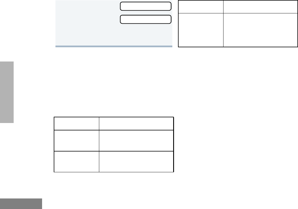
66
English
SCAN
PRIORITIZING A TALKGROUP OR
CHANNEL IN A SCAN LIST
(SYSTEM SCAN OPERATION ONLY)
You may want to check the activity on one or
two talkgroups or channels more frequently
than others. You can do this by prioritizing
them:
Note: In Conventional operation only, even if
there is activity on a non-priority channel,
your radio automatically switches to an
active priority channel and indicates the
activity with a short tone.
11 ( to return to
to return to
–or–
Hold down t to exit menu mode.
Priority Channel Scanning Sequence
None specified Ch1➠Ch2➠Ch3➠
Ch4➠…Ch1
Channel 2
(Priority 1) Ch2➠Ch1➠Ch2➠Ch3➠
Ch2➠Ch4➠Ch2➠…Ch1
Add Entry?
Delete Entry? Channel 2
(Priority 1) and
Channel 8
(Priority 2)
Ch2➠Ch1➠Ch8➠Ch3➠
Ch2➠Ch4➠Ch8➠…Ch1
Priority Channel Scanning Sequence

67
English
SCAN
Setting Priority Talkgroups or Channels
1) to enter menu mode.
2y or z until
3) to select
4y or z until
5) to select
6y or z until
7) to select
8y or z until
or until
You see the current priority talkgroup or
channel.
9) to select the desired priority level.
10 y or z until you see the talkgroup or
channel you want to prioritize.
Program Lists
Program Lists
Scan List
Scan List
Edit Priority?
Edit Priority?
Priority #1?
Priority #2?
11 ) to prioritize that talkgroup or
channel.
12 ( to return to
–or–
Hold down ( to exit menu mode.
Note: You cannot reprioritize a priority 1 talk-
group or channel to priority 2.
Edit Priority?

68
English
SCAN
Notes

69
English
PHONE
PHONE
Your radio allows you to place and receive
telephone calls through trunked and
conventional systems (depending on phone
line availability). Telephone calls through a
repeater allow only one person to speak at a
time.
MAKING A PHONE CALL D
THROUGH A TRUNKED SYSTEM
Note: The following instructions assume your
radio has been programmed as follows by
your dealer using CPS (Customer Program-
ming Software).
• Dial type: Live
• Access/Deaccess type: Immediate Auto
• Tone Span: Timed - 100 ms tone duration
To Initiate a Phone Call
Do the following:
1Select a trunked zone and talkgroup that
have been programmed for telephone.
2) to enter menu mode.
–or–
Press the preprogrammed radio or DTMF
microphone Phone button, and skip to
step 5.
–or–
a. Press and release the Speed Dial
button to use the speed dial feature.
b. Press the (1 to 9) key corresponding
to the number you want to call on the
Phone list. Or press 0 if you want to
call the last number dialed.
c. Press the PTT button. A dial tone
sounds.
d. Press the PTT button again to send
the phone number.
–or–
For LTR trunked systems, press and hold
the PTT button while dialing a number.
3y or z until
4 ) to confirm
Phone
Phone

70
English
PHONE
MAKING A PHONE CALL D
THROUGH A CONVENTIONAL
SYSTEM
To Initiate a Phone Call
Press the preprogrammed Phone button, and
skip to step 5.
–or–
Press the PTT button, and if the Hot keypad
feature has been programmed by your dealer,
do the following:
D appears on the display when you are
in Phone mode.
5Press and Release the PTT button.
• If phone access is successful, a dial
tone sounds.
• If phone access is unsuccessful, a
low-pitched alternating tone sounds.
Disconnect the call (see step 8) and
try again.
6Enter the phone number with the DTMF
microphone. The number is automatically
sent without pressing the PTT button
again.
–or–
y or z to
select a number
from the phone list.
Press and release the PTT button again
to send the number.
XXX-XXX-XXXX
7Hold the radio in a vertical position with
the microphone 1 to 2 inches (2.5 to 5
cm) away from your mouth. Press the
PTT button to talk; release it to listen.
8To disconnect the phone call:
Press and hold ( to exit Phone.
D no longer appears on the display.
1Select a conventional zone and channel
that have been programmed for tele-
phone.

71
English
PHONE
2) to enter menu mode.
3y or z until
4) to select
D appears on the display when you are
in Phone Mode.
5(For conventional operation with auto
access only). You hear a series of tones,
indicating that an access code is being
sent automatically, and see your access
code:
–or–
Enter your access code using the DTMF
microphone keypad.
6When you hear a dial tone:
Enter the phone
number using the
DTMF microphone
keypad.
–or–
Phone
Phone
XXX-XXX-XXXX
y or z to
select a number
from the phone list.
–or– (see step 7)
7a. Press and release the prepro-
grammed Speed Dial button (see
step 6) to use the Speed Dial fea-
ture.
b. Press the key (1 to 9) corresponding
to the number you want to call, or
press 0 if you want to call the last
number dialed.
Note: To redial the last number dialed (if
not using Speed Dial), press and
release the PTT button immediately
after the access code is sent. The
radio sends the last number dialed.
–or–
If you entered your access code
using the keypad, press z once
to access the last number dialed;
then press and release the PTT but-
ton.
XXX-XXX-XXXX

72
English
PHONE
RECEIVING A PHONE CALL D
THROUGH A TRUNKED OR
CONVENTIONAL SYSTEM
To Receive a Phone Call
8Press and release the PTT button, if
required for your radio.
9Hold the radio in a vertical position with
the microphone 1 to 2 inches (2.5 to 5
cm) away from your mouth. Press the
PTT button to talk; release it to listen.
10 To disconnect a phone call, do one of the
following:
Enter the deaccess code using the DTMF
microphone keypad.
–or–
If your radio has the deaccess code
programmed, go to step 9.
11 To exit Phone Mode:
Press and hold # to disconnect the
call. D disappears from the display.
1y o r z to select a LTR talkgroup or
conventional channel that has been
programmed for telephone.
–or–
Activate any scan type containing a tele-
phone talkgroup or channel (see page
59).
Note: No PassPort talkgroup or zone
selection is needed in PassPort
mode.
• When a phone call is received, a ring-
ing tone sounds, alerting you to
answer the phone call.
Note: The D also appears on the display in
PassPort mode.

73
English
PHONE
MODIFYING THE PHONE LIST K
Your radio contains a Phone list that holds up
to 25 phone numbers. The Phone list is shared
between trunked and conventional Phone
operation. You can modify the Phone list in
three ways through your radio’s menu:
• Add an entry
• Delete an entry
• Edit an existing entry
The K symbol appears on the display when
you are modifying the phone list.
To Add an Entry
2Press the PTT button to answer the
phone call. Press the PTT button to talk;
release it to listen.
3To disconnect the phone call and exit
Phone and menu mode:
Press and hold to disconnect the call.
Note: D no longer appears on the display
in PassPort mode.
1) to enter menu mode.
2y or z until
3) to select
4y or z until
5) to select
6y or z until
7) to select,
you see:
8Use the DTMF microphone keypad to
enter the name (see page 23 and page
24).
9) to store the name,
you see:
Program Lists
Program Lists
Phone List
Phone List
Add Entry?
Add Entry?
Entry Name
Enter Phone #

74
English
PHONE
To Delete an Entry
10 Use the DTMF microphone keypad to enter
the phone number. You can also add a dash
(press w) and a Pause Indicator (hold
down # until the # character on the dis-
play changes to a “P”).
11 ) to store the phone number.
12 y or z until you see the location in
the list where you want to store the phone
number.
13 ) to store the phone number,
you see:
14 ) to return to
Hold down ( to exit menu mode.
1) to enter menu mode.
2y or z until
Entry Saved
Add Entry?
Program Lists
3) to select
4y or z until
5) to select
6y or z until
7) to select
8y or z until you see the entry you
want to delete.
9) to select the entry,
you see:
10 ) again to confirm the deletion,
you see:
11 ( to return to
–or–
Hold down ( to exit menu mode.
Program Lists
Phone List
Phone List
Delete Entry?
Delete Entry?
Delete?
Entry Deleted
Delete Entry?

75
English
PHONE
To Edit an Entry
1) to enter menu mode.
2y or z until
3) to select
4y or z until
5) to select
6y or z until
7) to select
8y or z until you see the entry you
want to edit.
9) to select the entry.
Program Lists
Program Lists
Phone List
Phone List
Edit Entry?
Edit Entry?
10 y or z until
(to edit the name),
or until
(to edit the phone number),
or until
(to edit the location in the phone list).
11 ) to confirm your selection.
12 Use the DTMF microphone keypad to
edit the entry (see page 19),
–or–
y or z until you see the location
where you want to store the phone num-
ber.
13 ) to store the information.
14 ( to return to
–or–
Hold down ( to exit menu mode.
Edit Name?
Edit Number?
Edit Location?
Edit Entry?

76
English
PHONE
Notes
77
English
VOICE STORAGE
VOICE STORAGE
The CDM1550•LS+ radio’s voice storage feature
enables your radio to perform seven types of
voice related functions:
• Incoming Call Recording
• Voice Memo Recording
• Recorded Message Playback
• Recorded Message Delete
• Recorded Message Transmission
• Automatic Message Reply (“When
Available”)
• Message Time Stamping
There is a total of 120 seconds recording time
available for all voice storage activity. Your
dealer can divide the 120 seconds into a
defined number of equal length time slots. The
following table summarizes the slot length
options available with the CDM1550•LS+ radio:
When recording calls, keep in mind these
time slot guidelines:
Number of Equal
Length Slots Slot Length
(Seconds)
1120
260
524
10 12
20 6
• As a time slot becomes close to full, you
see a timer count down the final 5
seconds.
When a time slot is completely full, an
alert tone sounds
The display shows:
Recording stops.
• When all message slots have at least one
message stored, an alert tone sounds.
Msg Slot Full

78
English
VOICE STORAGE
INCOMING CALL RECORDING
The CDM1550•LS+ radio allows you to record
incoming calls in either of two ways:
• Selective Incoming Call Recording
• All Incoming Call Recording
Note: Only the audio transmissions of your caller
is recorded.
Selective Incoming Call Recording
This feature enables you to record incoming
calls selectively, or on a call-by-call basis.
To Selectively Record an Incoming Call
All Incoming Call Recording
This feature enables you to automatically
record all incoming trunked and conventional
dispatch calls, trunked and conventional
telephone interconnect calls, and MDC
selective calls.
This feature is useful when you need to keep
informed of channel activity while away from
your radio.
Note: This feature does not work while in scan
mode.
If a voice storage
record function is
requested, the dis-
play shows:
1Press and hold the preprogrammed
Record/Playback button (see page 26)
while receiving the call.
The display shows
Memory Full
Recording
A confirmation tone sounds, indicating
that the radio begins recording.
2The radio records the call until the mes-
sage slot is full or until you release the
preprogrammed Record/Playback but-
ton.
3Release the Record/Playback button to
stop recording.

79
English
VOICE STORAGE
To Record All Incoming Calls
1) to enter menu mode.
2y or z until
3) to select
4y or z until
5) to select
6y or z until
7) to select
8The display contin-
uously flashes,
except while a call
is being recorded.
Voice Storage
Voice Storage
Record
Record
All Incoming
All Incoming
All Incoming
9The display shows while your radio is
recording.
The radio also records the time stamp
and the channel alias to the message
slot.
10 Press ( to stop recording.
–or–
Go to step 1 again to continue recording
in the next available slot.
Note: Five seconds
before the message
slot ends, the radio
display shows
(where XX = remaining seconds).
The “voice storage full” alert sounds when the
message slot is full, and recording stops.
The display shows:
Recording
Time Left XX
Msg Slot Full

80
English
VOICE STORAGE
VOICE MEMO RECORDING
In addition to recording calls received, the
CDM1550•LS+ radio offers you the ability to
record voice memos (or personal reminders)
into the radio. The voice memo recording
feature is useful for quickly saving phone
numbers, names, or any other brief voice
information. You can record voice memos using
the preprogrammed Record/Playback button
(see page 26) or your radio’s menu.
Important Note:
To record properly, incoming calls cannot be
received while a voice memo is being
recorded.
To Record a Voice Memo using the
Preprogrammed Record/Playback Button
To Record a Voice Memo using the Menu
1Press and hold the preprogrammed
Record/Playback button.
• The display shows:
• A confirmation tone sounds, indicating
that the radio begins recording.
Recording
2Without pressing the PTT button, speak
clearly into the microphone to record your
memo. The radio records your memo
until the message slot is full or until you
release the preprogrammed Record/
Playback button.
3Release the Record/Playback button to
stop recording.
1) to enter menu mode.
2y or z until
3) to select
4y or z until
5) to select
6y or z until
7) t o se le ct
Voice Storage
Voice Storage
Record
Record
Voice Memo
Recording

81
English
VOICE STORAGE
RECORDED MESSAGE PLAYBACK
The CDM1550•LS+ allows you to list, select,
and Playback previously recorded incoming
call or voice memo messages. You can play
back a message by using the preprogrammed
Record/Playback button (see page 26) or your
radio’s menu.
Note: Recorded message Playback cannot be
initiated while your radio is receiving. Also,
you don’t receive any incoming calls while
you play back messages.
To Playback a Message using the
Preprogrammed Record/Playback Button
8Without pressing the PTT button, speak
clearly into the microphone to record your
memo. The radio records your memo
until the message slot is full or until you
press (.
Note: To stop recording at any time, press
(.
9Press ( to stop recording.
–or–
Repeat steps 7 and 8 to store additional
messages.
Playing Msg XXX
1Press and release the preprogrammed
Record/Playback button.
• The first mes-
sage plays, and
the display shows (XXX = the mes-
sage number)
2To advance to the next message at any
time during Play back, press and release
the Record/Playback button again.
3To exit/cancel Playback mode:
Press and release the preprogrammed
Playback Exit button (see page 26).
–or–
Press ( to stop Play Back.
Playing Msg XXX
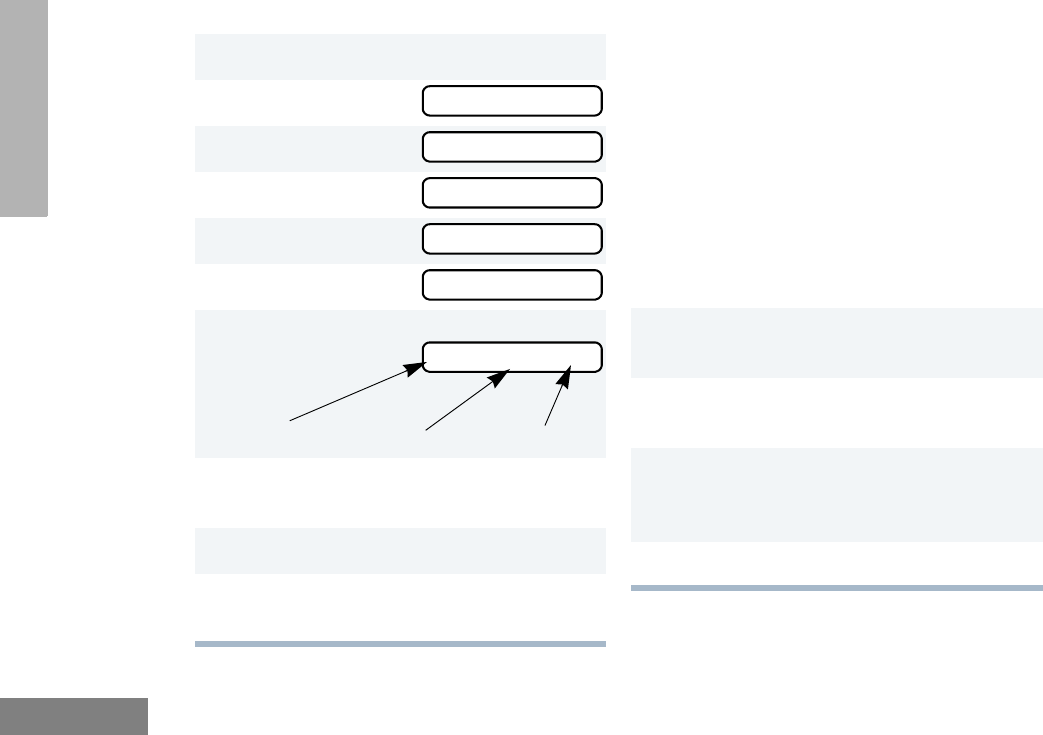
82
English
VOICE STORAGE
To Playback a Message using the Menu RECORDED MESSAGE DELETE
The CDM1550•LS+ radio allows you to delete
previously recorded incoming call or voice
memo messages. You can delete a message
using either the preprogrammed Delete
Playback button (see page 26) or your radio’s
menu.
Note: Messages must be deleted one at a time.
To Delete a Message using the
Preprogrammed Delete Playback Button
(see page 26)
1) to enter menu mode.
2y or z until
3) to select
4y or z until
5) to select
6y or z until
7) to select
8y or z to select the desired mes-
sage.
9Press ) to play the selected message.
10 y or z anytime during playback to
advance to the next message.
Voice Storage
Voice Storage
Playback
Playback
001 12:00A 005
001 12:00A 005
1Press and release the preprogrammed
Record/Playback button.
2y or z to select the desired mes-
sage.
3Press and hold the preprogrammed
Delete Playback button to delete current
message.
4( to stop deleting messages.
Time Stamp
Message # Duration (in seconds)

83
English
VOICE STORAGE
To Delete a Message using the Menu RECORDED MESSAGE
TRANSMISSION
This feature allows you to transmit a recorded
message to another radio user.
To Transmit a Recorded Message
1) to enter menu mode.
2y or z until
3) to select
4y or z until
5) to select
6y or z to select the desired mes-
sage.
7Press ) to delete the selected mes-
sage.
8y or z to select the another mes-
sage to be deleted, then go to step 7.
–or–
Press ( to stop deleting messages.
Voice Storage
Voice Storage
Delete
Delete
1Press and hold the PTT button to initiate
the message transmission.
2While holding down the PTT button,
press the preprogrammed Record/Play-
back button to select and play back the
desired recorded call or memo.
3When finished transmitting your mes-
sage, press the Record/Playback but-
ton again to stop transmitting.
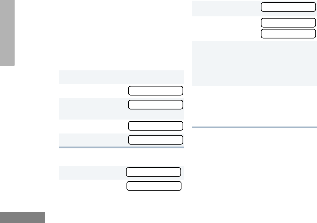
84
English
VOICE STORAGE
ANSWER MODE
The Answer Mode feature allows radio callers
to leave recorded audio messages on your
radio.
Note: This feature is available via the radio’s
menu and/or the radio or the DTMF micro-
phone programmable button.
To Enable the Answer Mode Feature
To Record a Message
1) to enter menu mode.
2y or z until
3) to select
Voice Storage
4y or z until
5) to select
1y or z until
2) to select
Voice Storage
Voice Storage
Ans Mode On?
Ans Mode On
Record Msg
Greeting Msg?
3y or z until
4) to select
T h e d i s p l ay s h o w s :
5Without pressing the PTT button, speak
clearly into the microphone to record your
memo. The radio records your greeting
until the message slot is full or until you
press (.
6To exit or cancel recording, press (.
With this feature enabled, the recorded
message is automatically transmitted
whenever your radio receives a call.
Alternate Msg?
Greeting Msg?
Recording

85
English
VOICE STORAGE
To Disable the Answer Mode Feature
1) to enter menu mode.
2y or z until
3) to select
4y or z until
5) to select
Voice Storage
Voice Storage
Ans Mode Off?
Ans Mode Off

86
English
VOICE STORAGE
Notes

87
English
AUDIO/TONE
SETTINGS
AUDIO/TONE SETTINGS
You can customize the audio and tone feature
settings on your radio by:
1) to enter menu mode.
2y or z until
3) to select
4y or z until you see the feature you
want to change (see the table on the next
page).
5) to select the feature. You see the
feature’s current setting.
6y or z for available settings. (For
Name and Call Tone Tagging, see
page 56.)
7) to set the desired setting.
Audio/Tones
Audio/Tones

88
English
AUDIO/TONE
SETTINGS
Audio/Tone Settings
Feature What it Does Settings
Alert Vol Lvl Makes the volume level of the audio and alert tones inde-
pendent. If turned on, it makes the alert tones follow the
settings in the CPS; if turned off, the alert tones follow the
setting of the volume knob.
Ind Alert Off
Ind Alert On
Tone Disable Turns all alert and audio tones on or off. Tones On
Tones Off
Name and Call
Tone Tagging ‡§
Assigns a specific ring tone when receiving a call from a
specific user (see page 56 for details).
Standard
Alert #1 – #7
Call Tone Tag ठAssigns a specific tone when receiving a specific type of
radio call (see page 56 for details).
Standard
Alert #1 – #7
Escalert ‡Increases the volume of the alarm tones when a radio
call is not answered.
Escalert On
Escalert Off
Companding Provides the same audio quality for 12.5 kHz and for
25 kHz channels.
Compand On
Compand Off
‡ LTR trunking operation only. § Conventional operation only.

89
English
UTILITIES
UTILITIES
You can customize some of your radio’s feature
by:
1) to enter menu mode.
2y or z until
3) to select
4y or z until you see the feature you
want to change (see table on the next
page).
5) to select the feature. You see the
feature’s current setting.
6y or z for available settings.
7) to select the desired setting.
Utilities
Utilities

90
English
UTILITIES
Utilities Features
Feature What it Does Settings
Power Level Changes the power level of the radio to high, low (see
page 91).
Power High
Power Low
Clock Sets the time, or turns the clock on or off (see page 92). Clock On
Clock Off
Set Time
Reminder Alarm Sets the alarm, or turns it on or off (see page 92). Alarm On
Alarm Off
Set Time
Language
Selection § ‡
Selects the language to be shown on your radio’s dis-
plays.
English
Spanish
Portuguese
French
Software Ver # In LTR trunked and conventional operation, displays the
radio’s software version number when you press ).
In PassPort operation, displays the PassPort software
version number when you press ).
Note: The LTR and conventional software version number may
be different than the PassPort software version number.
——
§ Conventional Operation only. ‡ LTR Trunked Operation only.
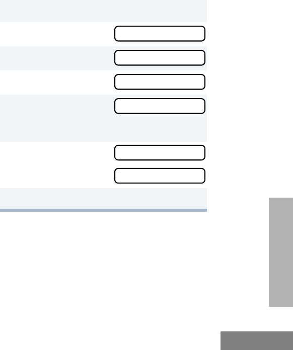
91
English
UTILITIES
SETTING THE POWER LEVEL B
Each channel in your radio has a predefined
transmit power level that can be changed.
•High power (S) allows you to reach a radio
that is farther away.
•Low power (R) conserves the battery’s
charge.
Note:
• Be aware that a message received
from a nearby radio might change
your radio’s power level to low. This
may cause radios that are farther
away not to receive your transmis-
sions.
• In PassPort mode, the power level is
predefined radio wide.
To set the power level:
Press the preprogrammed Power Level button
(see page 25) to toggle between low and high,
–or–
Do the following:
1) to enter menu mode.
2y or z until
3) to select
4y or z until
5) to select
The display shows the current power level.
6y or z until
or until
7) to confirm the selection.
Utilities
Utilities
Power Level
Power Level
Power High?
Power Low?
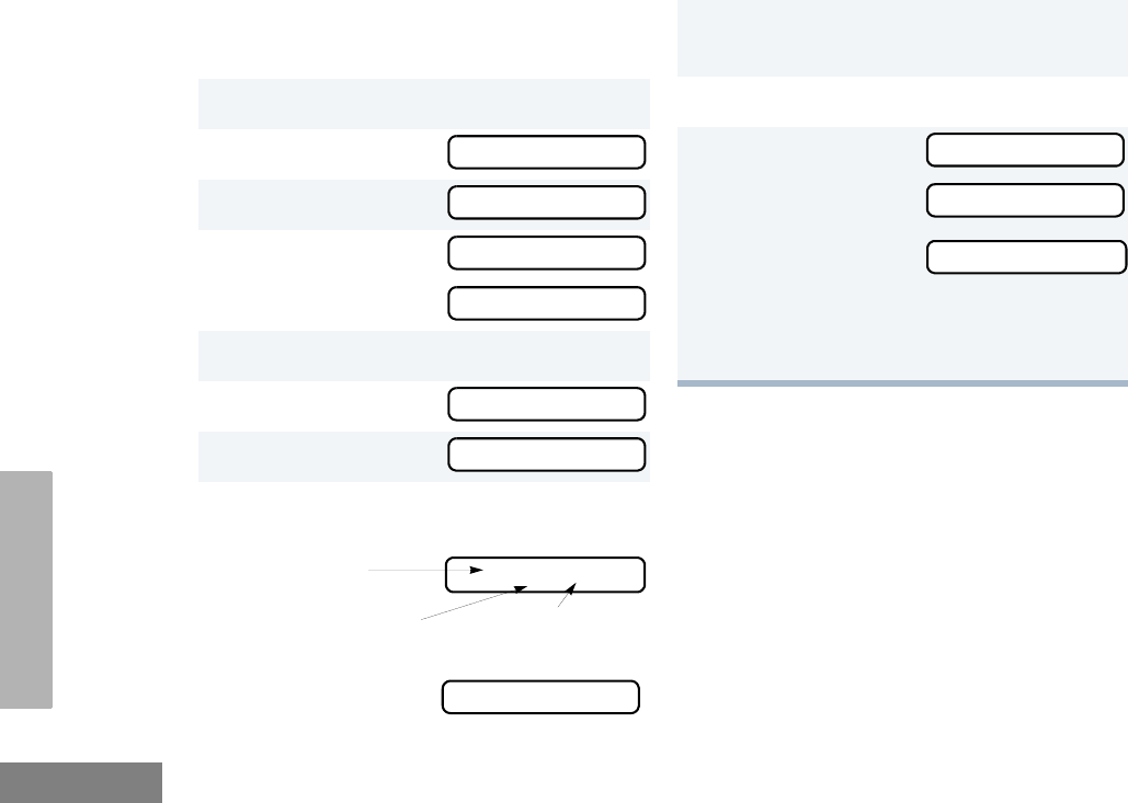
92
English
UTILITIES
SETTING THE CLOCK/ALARM
To Set the Clock/Alarm
1) to enter menu mode.
2y or z until
3) to select
4y or z until
or until
5) to confirm your selection.
6y or z until
7) to select
8When a setting is blinking, you can
change it with y or z.
Note: You cannot select “24 hr” for
Utilities
Set time?
Clock
Reminder Alarm
Set time?
Set time?
Hour (AM or
PM)
(AM/PM or 24 hr) Minutes
3:05 PM
Reminder Alarm
9v or w to move to the previous or
next setting.
10 ) to save your changes.
11 ( to return to
–or– to return to
–or–
–or–
Hold down ( to exit menu mode.
Utilities
Reminder Alarm
Clock

93
English
UTILITIES
DISPLAYING THE TIME
To Display the Time
SELECTING THE DISPLAY
LANGUAGE
(LTR TRUNKED AND CONVENTIONAL
OPERATION ONLY)
To Select the Display Language
1) to enter menu mode.
2y or z until
3) to select
4y or z until
5) to confirm your selection.
6y or z until
7) to select
The radio displays
the time for a pre-
programmed dura-
tion.
8( to exit the menu.
Utilities
Utilities
Clock
Display Clock?
Display Clock?
1) to enter menu mode.
2y or z until
3) to select
4y or z until
5) to confirm your selection.
6y or z until the desired language is
displayed.
7) to confirm your selection.
8( to exit the menu.
Utilities
Utilities
Language Select

94
English
UTILITIES
Notes

95
English
WARRANTY
WARRANTY
LIMITED WARRANTY
MOTOROLA COMMUNICATION
PRODUCTS
I. WHAT THIS WARRANTY COVERS AND
FOR HOW LONG:
MOTOROLA INC. (“MOTOROLA”) warrants the
MOTOROLA manufactured Communication
Products listed below (“Product”) against defects
in material and workmanship under normal use
and service for a period of time from the date of
purchase as scheduled below:
CDM1550•LS+ Mobile Units Two (2) Years
Product Accessories One (1) Year
Motorola, at its option, will at no charge either
repair the Product (with new or reconditioned
parts), replace it (with a new or reconditioned
Product), or refund the purchase price of the
Product during the warranty period provided it is
returned in accordance with the terms of this
warranty. Replaced parts or boards are warranted
for the balance of the original applicable warranty
period. All replaced parts of Product shall become
the property of MOTOROLA.
This express limited warranty is extended by
MOTOROLA to the original end user purchaser
only and is not assignable or transferable to any
other party. This is the complete warranty for the
Product manufactured by MOTOROLA.
MOTOROLA assumes no obligations or liability
for additions or modifications to this warranty
unless made in writing and signed by an officer
of MOTOROLA. Unless made in a separate
agreement between MOTOROLA and the
original end user purchaser, MOTOROLA does
not warrant the installation, maintenance or
service of the Product.
MOTOROLA cannot be responsible in any way
for any ancillary equipment not furnished by
MOTOROLA which is attached to or used in
connection with the Product, or for operation of
the Product with any ancillary equipment, and all
such equipment is expressly excluded from this
warranty. Because each system which may use
the Product is unique, MOTOROLA disclaims
liability for range, coverage, or operation of the
system as a whole under this warranty.
12_Warranty.fm Page 95 Monday, April 15, 2002 5:09 PM

96
English
WARRANTY
II. GENERAL PROVISIONS:
This warranty sets forth the full extent of
MOTOROLA'S responsibilities regarding the
Product. Repair, replacement or refund of the
purchase price, at MOTOROLA’s option, is the
exclusive remedy. THIS WARRANTY IS GIVEN
IN LIEU OF ALL OTHER EXPRESS
WARRANTIES. IMPLIED WARRANTIES,
INCLUDING WITHOUT LIMITATION, IMPLIED
WARRANTIES OF MERCHANTABILITY AND
FITNESS FOR A PARTICULAR PURPOSE, ARE
LIMITED TO THE DURATION OF THIS LIMITED
WARRANTY. IN NO EVENT SHALL MOTOROLA
BE LIABLE FOR DAMAGES IN EXCESS OF
THE PURCHASE PRICE OF THE PRODUCT,
FOR ANY LOSS OF USE, LOSS OF TIME,
INCONVENIENCE, COMMERCIAL LOSS, LOST
PROFITS OR SAVINGS OR OTHER
INCIDENTAL, SPECIAL OR CONSEQUENTIAL
DAMAGES ARISING OUT OF THE USE OR
INABILITY TO USE SUCH PRODUCT, TO THE
FULL EXTENT SUCH MAY BE DISCLAIMED BY
LAW.
III. STATE LAW RIGHTS:
SOME STATES DO NOT ALLOW THE
EXCLUSION OR LIMITATION OF INCIDENTAL
OR CONSEQUENTIAL DAMAGES OR
LIMITATION ON HOW LONG AN IMPLIED
WARRANTY LASTS, SO THE ABOVE
LIMITATION OR EXCLUSIONS MAY NOT
APPLY.
This warranty gives specific legal rights, and there
may be other rights which may vary from state to
state.
IV. HOW TO GET WARRANTY SERVICE:
You must provide proof of purchase (bearing the
date of purchase and Product item serial
number) in order to receive warranty service and,
also, deliver or send the Product item,
transportation and insurance prepaid, to an
authorized warranty service location. Warranty
service will be provided by Motorola through one
of its authorized warranty service locations. If you
first contact the company which sold you the
Product (e.g., dealer or communication service
provider), it can facilitate your obtaining warranty
service. You can also call Motorola at 1-800-927-
2744 US/Canada.
12_Warranty.fm Page 96 Monday, April 15, 2002 5:09 PM

97
English
WARRANTY
V. WHAT THIS WARRANTY DOES NOT
COVER:
A) Defects or damage resulting from use of the
Product in other than its normal and
customary manner.
B) Defects or damage from misuse, accident,
water, or neglect.
C) Defects or damage from improper testing,
operation, maintenance, installation,
alteration, modification, or adjustment.
D) Breakage or damage to antennas unless
caused directly by defects in material
workmanship.
E) A Product subjected to unauthorized
Product modifications, disassembles or
repairs (including, without limitation, the
addition to the Product of non-Motorola
supplied equipment) which adversely affect
performance of the Product or interfere with
Motorola's normal warranty inspection and
testing of the Product to verify any warranty
claim.
F) Product which has had the serial number
removed or made illegible.
G) Rechargeable batteries if:
1) any of the seals on the battery
enclosure of cells are broken or show
evidence of tampering.
2) the damage or defect is caused by
charging or using the battery in
equipment or service other than the
Product for which it is specified.
H) Freight costs to the repair depot.
I) A Product which, due to illegal or
unauthorized alteration of the software/
firmware in the Product, does not function in
accordance with MOTOROLA’s published
specifications or the FCC type acceptance
labeling in effect for the Product at the time
the Product was initially distributed from
MOTOROLA.
J) Scratches or other cosmetic damage to
Product surfaces that does not affect the
operation of the Product.
K) Normal and customary wear and tear.
VI. PATENT AND SOFTWARE PROVISIONS:
MOTOROLA will defend, at its own expense, any
suit brought against the end user purchaser to
the extent that it is based on a claim that the
Product or parts infringe a United States patent,
and MOTOROLA will pay those costs and
damages finally awarded against the end user
purchaser in any such suit which are attributable
to any such claim, but such defense and
payments are conditioned on the following:
12_Warranty.fm Page 97 Monday, April 15, 2002 5:09 PM

98
English
WARRANTY
A) that MOTOROLA will be notified promptly in
writing by such purchaser of any notice of
such claim;
B) that MOTOROLA will have sole control of the
defense of such suit and all negotiations for
its settlement or compromise; and
C) should the Product or parts become, or in
MOTOROLA’s opinion be likely to become,
the subject of a claim of infringement of a
United States patent, that such purchaser
will permit MOTOROLA, at its option and
expense, either to procure for such
purchaser the right to continue using the
Product or parts or to replace or modify the
same so that it becomes non-infringing or to
grant such purchaser a credit for the Product
or parts as depreciated and accept its
return. The depreciation will be an equal
amount per year over the lifetime of the
Product or parts as established by
MOTOROLA.
MOTOROLA will have no liability with respect to
any claim of patent infringement which is based
upon the combination of the Product or parts
furnished hereunder with software, apparatus or
devices not furnished by MOTOROLA, nor will
MOTOROLA have any liability for the use of
ancillary equipment or software not furnished by
MOTOROLA which is attached to or used in
connection with the Product. The foregoing
states the entire liability of MOTOROLA with
respect to infringement of patents by the Product
or any parts thereof.
Laws in the United States and other countries
preserve for MOTOROLA certain exclusive rights
for copyrighted MOTOROLA software such as
the exclusive rights to reproduce in copies and
distribute copies of such Motorola software.
MOTOROLA software may be used in only the
Product in which the software was originally
embodied and such software in such Product
may not be replaced, copied, distributed,
modified in any way, or used to produce any
derivative thereof. No other use including, without
limitation, alteration, modification, reproduction,
distribution, or reverse engineering of such
MOTOROLA software or exercise of rights in
such MOTOROLA software is permitted. No
license is granted by implication, estoppel or
otherwise under MOTOROLA patent rights or
copyrights.
VII. GOVERNING LAW:
This Warranty is governed by the laws of the
State of Illinois, USA.
12_Warranty.fm Page 98 Monday, April 15, 2002 5:09 PM

99
English
ACCESSORIES
ACCESSORIES
Motorola offers a number of accessories to
enhance the productivity of your two-way radio.
Many of the available accessories are listed
below. For a complete list, see your Motorola
dealer.
MICROPHONES
HANDSFREE KITS
EXCHANGEABLE BUTTON KITS
Note: Other individual exchangeable buttons
are available through AAD. Please see
Basic Service Manual for button
numbers.
MOUNTING KITS
AARMN4025_ Standard Compact Microphone
AARMN4026_ Enhanced DTMF Keypad Microphone
AARMN4038_ Heavy Duty Microphone
AAREX4617_ Telephone Style Handset with Hang-Up
Cup
HLN9073_R Microphone Hang-Up Clip (all
microphones)
AARMN4027_ Visor Mounted Microphone
RLN4856_ Footswitch PTT
RLN4857_ Pushbutton PTT
RLN4858_ Gooseneck PTT
RLN4831_ Standard Button Kit: MON, SCAN, CALL,
HOME, PHONE
RLN5324_ Standard Button Kit: MON, SCAN, CALL,
HOME, PHONE, ROAM, SITE
GLN7324_R Standard Low Profile Bracket (VHF/UHF)
GLN7317_ High Profile Mounting Bracket (VHF/UHF)
RLN4779_ Key Lock Mounting Bracket (VHF/UHF)
RLN4781_ Direct in Dashboard Mounting Kit (VHF/
UHF)
HLN8097_ Removable Slide Mount Tray Package
(VHF/UHF - A maximum of two external
accessory wires can be attached to the
slide tray)
13_Accessory.fm Page 99 Monday, April 15, 2002 5:09 PM

100
English
ACCESSORIES
REMOTE MOUNTS
EXTERNAL SPEAKERS
INSTALLATION AND ALARM KITS
ANTENNAS
SERVICE AIDS AND
PROGRAMMING EQUIPMENT
RLN4802_ Remote Mount Kit - CDM1250 and
CDM1550 models (requires HKN4192
power cable)
RKN4077_ Remote Mount Cable, 3 meter length
RKN4078_ Remote Mount Cable, 5 meter length
RKN4079_ Remote Mount Cable, 7 meter length
RSN4001_ 13 Watt External Loudspeaker
HSN8145_ 7.5 Watt External Speaker - for Receiver
Audio
HKN4137_ Standard 12V 10” Power Cable to Battery
(VHF/UHF)
HKN4192_ 12V 20 Ft. Power Cable to Battery (VHF/
UHF)
GKN6272_ External Alarm Relay and Cable
RLN4836_ Emergency Footswitch
HKN9327_ Ignition Switch Cable
HKN9557_R PL259/Mini-U Antenna Adapter - 8” Cable
HLN9457_R Hardware Kit for use with the Expanded
Accessory Connector (includes 16
connector pins, (five) 8” wires with pins
attached and an extra housing)
HKAD4001_ 220 MHz, 1/4-Wave Roof Mount
HAF4012_ Mini-U 746-794 MHz, 1/4-Wave Roof
Mount
H5177 Portable/Mobile Programming Software
(CPS) 3 Year Subscription Package -
Includes CPS CD ROM Software:
HVN9025 for the HT/EX500/CDM/MTX.LS
Series and HVN9067 for MTX Series
Privacy Plus. Includes HT/MTX Series
Programming/Test Cable (AARKN4074).
Also is compatible with RLN4460 used for
radio testing. (HVN9025 is compatible with
Windows® 95/98/2000/Millennium (ME)/
Windows NT®. HVN9067 is compatible
with Windows® 95/98/Windows NT®).
Note: Software requires a license
agreement and is not intended for
resale.
13_Accessory.fm Page 100 Monday, April 15, 2002 5:09 PM

101
English
ACCESSORIES
MANUALS
CONTROL STATION KITS
MOBILE DATA UNITS SECTION
Terminals:
AARKN4081_ Programming Cable with Internal RIB
(direct connection from computer to radio
microphone connector)
AARKN4083_ Programming Cable (allows radio
programming via rear accessory
connector)
3080070N01 Programming Cable (connection from RIB
to radio)
3080369B72 9 Pin PC to Radio Interface Box Cable
(IBM AT or compatible)
RLN4460_ Test Box for Portables and Mobiles
RLN4008_ Radio Interface Box (RIB)
0180357A57 Wall Mounted Power Supply, 120V - used
with RLN4008
RLN4853_ 10 to 20 Pin Adapter
6864110R14 CDM1550•LS+ 220/700 MHz Detailed
Service Manual
6864110R16 CDM1550•LS+ 200/700 MHz Basic
Service Manual
6881092C58 Installation Manual (English)
HMN3000_ Desk Microphone (Black)
GLN7326_ Desktop Tray with Speaker
GLN7318_ Desktop Tray without Speaker
HKN9088_ Mobile Mini-U Antenna Adapter - 8 Ft.
Cable
HPN4002_R Power Supply and Cable (1-25 Watt
Models)
HPN4001_R Power Supply and Cable (25-60 Watt
Models)
RDN7365_ Mobile Status Terminal - Mobile
messaging device equipped with a data
modem. This will allow a mobile user to
report “status messaging” back to the
dispatcher by activating one of the status
keys.
RDN7366_ Mobile Status Terminal with GPS - Mobile
status terminal equipped with an
Automatic Vehicle Location (AVL) device
compatible with Global Positioning System
(GPS).
13_Accessory.fm Page 101 Monday, April 15, 2002 5:09 PM

102
English
ACCESSORIES
Radio Interface Cables: One radio interface
cable is required with purchase of each
hardware device
Peripherals:
Global Positioning System (GPS) Antennas:
Antenna is required with purchase of any GPS
unit
Software:
RDN7367_ Mobile Display Terminal with GPS - Mobile
display terminal equipped with an
Automatic Vehicle Location (AVL) device
compatible with Global Positioning system
(GPS).
RDN7368_ Mobile Display Terminal - Mobile
messaging device equipped with a data
modem. This unit features a 4x40 backlit
LCD display and the keypad allows users
to send information to the dispatcher in
response to base instructions.
RDN7369_ Standalone Modem/GPS - Cost efficient
Automatic Vehicle Location (AVL) device
compatible with Global Positioning System
(GPS).
RDN7738_ Serial Breakout Unit (used in multiple
applications that allow up to eight base
modems to be connected).
RDN7370_ 3 Ft. Interface Cable with 16 Pin
Connector
RDN7376_ 15 Ft. Interface Cable with 16 Pin
Connector
RDN7739_ 3 Ft. Flying Cable (same as regular
interface cable, but omits connectors).
RDN7740_ 15 Ft. Flying Cable (same as regular
interface cable, but omits connectors).
RDN7371_ Credit Card Reader - Card reader is used
to perform automatic online credit card
authorization transaction. Used with
RDN7379 (credit card software).
RDN7373_ Mobile Printer - The mobile printer
provides users with a hard copy of the
information transmitted from the base
dispatch location.
RDN7372_ Fixed Mount GPS Active Antenna
RDN7375_ Magnetic Mount GPS Active Antenna
RDN7374_ Programming Software - Used for mobile
data units.
RDN7377_ Regional Map Software - Will allow up to
10 selected US counties.
13_Accessory.fm Page 102 Monday, April 15, 2002 5:09 PM

103
English
ACCESSORIES
Miscellaneous:
PUBLIC ADDRESS
RETROFIT KIT
RDN7378_ AVL Messaging Status Software -
Mapping software that provides the user
with Automatic Vehicle Location to track
vehicles along with message dispatch and
status tracking capability.
RDN7379_ Credit Card Software - Used with
RDN7371 (credit card reader).
RDN7364_ Radio Channel Card - A radio channel
controller and modem that interface with
the base radio. Required with every radio
channel or wireless circuit used within the
system.
RDN7380_ Mobile Programming Hardware
RLN5288_ Public Address Kit (includes interface
cable
HKN9323_ 8 Ft. Public Address Speaker Cable
HKN9324_ 15 Ft. Public Address Speaker Cable (one
cable per speaker)
HSN1000_R 6 Watt Amplified External Speaker
6686119B01 Dismantling Tool
13_Accessory.fm Page 103 Monday, April 15, 2002 5:09 PM

104
English
ACCESSORIES
Notes:
13_Accessory.fm Page 104 Monday, April 15, 2002 5:09 PM
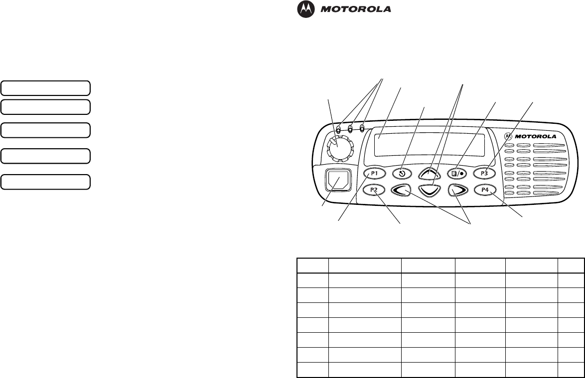
Selecting a Trunked Zone and Talkgroup
1. v or w to select desired trunked zone.
2. y or z until you see desired preprogrammed talkgroup on the display.
Sending a Trunked Call
1. Press PTT button. If trunked system access was successful — Red LED = steady;
if unsuccessful —LED = flashing; red-low pitched tone sounds.
2. Speak clearly into microphone. Release PTT button to listen.
Initial PassPort System Registration
Selecting a Conventional Zone and Channel
1. v or w to select desired conventional zone.
2. y or z until you see desired conventional channel on the display.
Sending a Conventional Call
• Press PTT button and speak clearly into microphone. LED = steady while call is being
sent. Release PTT button to listen.
Receiving a Trunked or Conventional Call
•v or w, then y or z to desired talkgroup or channel. Make sure PTT button
is released. When a call is received, the LED flashes.
Making a Selective Call (LTR Trunked and Conventional Operation only)
1. From Selective Call menu, select or enter desired radio ID number.
2. Press PTT button to send the call. The radio sounds a continuous tone.
3. Press PTT button and talk; release PTT button to listen.
Receiving a Selective Call (LTR Trunked and Conventional Operation only)
• When a Selective Call is received, the radio displays F symbol and name or ID of calling
radio; the yellow LED flashes. Press PTT button to answer.
Upon power up, PassPort alias appears on the LCD.
The selected talkgroup alias appears on the LCD.
May appear if a PassPort site cannot be quickly
located.
Appears indicating successful PassPort registration
(XXX = PassPort site on which you are registered).
Selected talkgroup alias appears and remains on the
display upon successful registration.
PASSPORT
TLKGRP ALIAS
SEARCHING
REG SITE XXX
TLKGRP ALIAS
CDM1550•LS+ Quick Reference Card
Record the functions for your radio’s programmable buttons in the table provided below. For further
information, see pages 24 and 25 in this User Guide.
Button Feature Short Press Long Press Hold Down Page
Zone Selector/
Editing Buttons
Menu Enter/Select
Button
(Interchangeable)
Programmable
Button 2 (P2) (Interchangeable)
Programmable
Button 4 (P4)
(Interchangeable)
Programmable
Button 3 (P3)
LCD Screen
Red/Yellow/Green
LED Indicators
Menu Exit/Escape
Button
(Interchangeable)
Programmable
Button 1 (P1)
(Left/Right)
Microphone
Jack
Control Knob
On/Off/Volume
Talkgroup/Channel Selector/
Menu Navigation Buttons
(Up/Down)
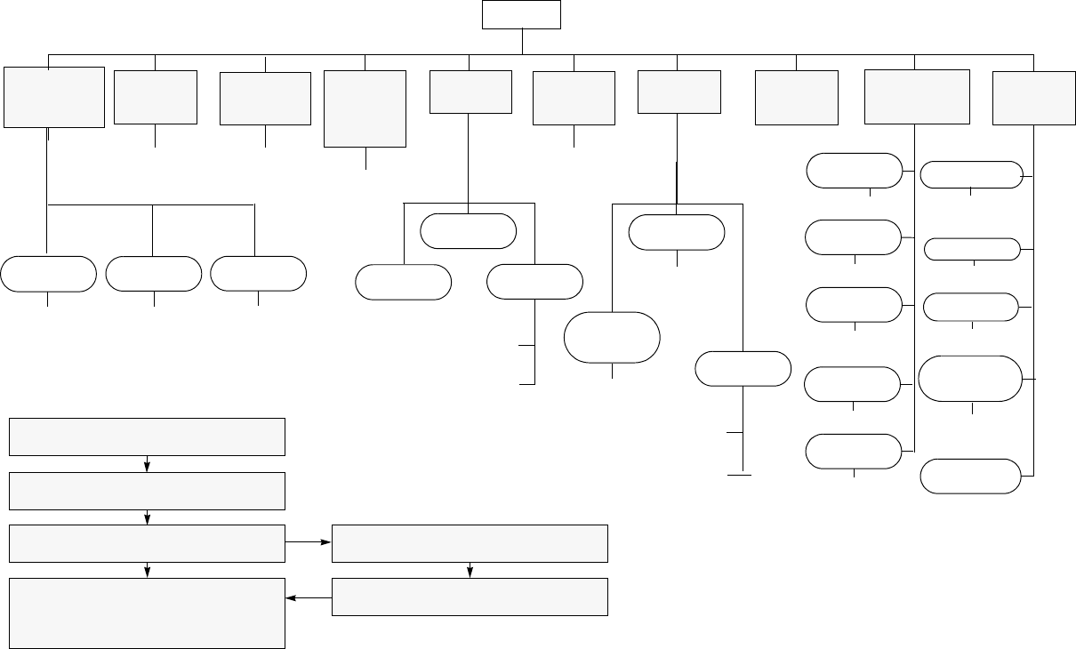
yz
Menu Navigation
)
on/off
Scan List
(p. 64)
Phone List
(p. 73)
add/delete
entry
edit
priority
(‡ and §)
Selective
Call‡§Call Alert
‡§Radio
Check‡§
Alert Vol Lvl
Tone
Disable
Escalert‡§
add/delete/
edit entry
edit entry
on/off
select/enter
ID
yz
yzyz
yz
select/enter
ID
repeater mode/
talkarnd mode
yz
select/enter
ID
yz
on/off
on/off
Companding
on/off
Call‡§
Tone Tag
standard/alert
#1 - #7
Power Level
high/low/
auto (‡ and §)
Clock
on/off/set time
) to enter menu mode
y or z to scroll through the list
) to select menu item
( to return to previous menu level
—or—
Hold down ( to exit menu mode
y or z to scroll through sub-list
) to select sub-menu item
RadioCall
List
(p. 55)
Phone
(p. 69)
Program
Lists
(LTR) All
Group
Scan‡(p. 62)
Audio/Tones
(p. 87) Utilities
(p. 89)
Rptr/
Talkarnd§
(p. 34)
Menu Navigation Chart
(Refer to Menu Navigation guidelines—
lower, left-hand corner of this page)
* — Available in PassPort trunked zones only
‡ — Available in LTR trunked zones only
§— Available in conventional zones only
on/off
yz
LTR /Con
System
Scan
on/off
yz
PP Group
Scan*
(p. 60)
Software
Version#
Record
(page 78)
Delete
(p. 82)
all incoming
voice
memo
yz
Voice
Storage
Playback
(p. 81)
Language
Selection‡§
English/French/
Portuguese/
Spanish
Radio Call
Reminder
Alarm
on/off/set time

Motorola, The Stylized M logo, Intelligence Everywhere, Professional Radio - As Dedicated As You Are, CDM Series,
CDM1550•LS+, and Call Alert are trademarks of Motorola, Inc.
LTR is a mark of E.F. Johnson Company.
PassPort is a registered trademark of Trident Datacomm Technologies, Inc.
© 2002 Motorola, Inc. All rights reserved. Printed in U.S.A.
*6864110R13-O*
6864110R13-O
CDM1550••LS++User Guide
Professional Radio - As Dedicated As You Are™
6864110R13-O_cvr.qxd 4/15/2002 3:46 PM Page 1