Motorola Solutions 99FT5001 CDM1550LS+ Mobile Radio User Manual 6864110R13 O cvr
Motorola Solutions, Inc. CDM1550LS+ Mobile Radio 6864110R13 O cvr
Contents
- 1. Ex 8a Users Manual Part 1
- 2. Ex 8b Users Manual Part 2
- 3. Antenna Installation Manual
Ex 8a Users Manual Part 1
Motorola, The Stylized M logo, Intelligence Everywhere, Professional Radio - As Dedicated As You Are, CDM Series,
CDM1550•LS+, and Call Alert are trademarks of Motorola, Inc.
LTR is a mark of E.F. Johnson Company.
PassPort is a mark of Trident Micro Systems.
© 2002 Motorola, Inc. All rights reserved. Printed in U.S.A.
*6864110R13-O*
6864110R13-O
CDM1550••LS++™
User Guide
Professional Radio - As Dedicated As You Are™
6864110R13-O_cvr.qxd 2/21/02 12:39 PM Page 1

1
English
CONTENTS
CONTENTS
Computer Software Copyrights . . . . . . . . . 6
Safety . . . . . . . . . . . . . . . . . . . . . . . . . . . . 7
User Safety, Training, and
General Information . . . . . . . . . . . . . . . . . . 7
Compliance with RF Energy Exposure
Standards. . . . . . . . . . . . . . . . . . . . . . . . . . 7
Operational Instructions and Training
Guidelines . . . . . . . . . . . . . . . . . . . . . . . . . 8
Transmit and Receive . . . . . . . . . . . . . . 8
Mobile Antennas . . . . . . . . . . . . . . . . . . 9
Approved Accessories . . . . . . . . . . . . . 9
Fixed Site Antennas . . . . . . . . . . . . . . . 9
Electromagnetic Interference/
Compatibility. . . . . . . . . . . . . . . . . . . . . . . 10
Facilities . . . . . . . . . . . . . . . . . . . . . . . 10
Vehicles . . . . . . . . . . . . . . . . . . . . . . . 10
Driver Safety . . . . . . . . . . . . . . . . . . . . 11
Operational Warnings . . . . . . . . . . . . . . . 11
For Vehicles With an Air Bag . . . . . . . 11
Potentially Explosive Atmospheres. . . 11
Blasting Caps and Areas . . . . . . . . . . 11
Introduction . . . . . . . . . . . . . . . . . . . . . . .13
Trunked Radio Systems . . . . . . . . . . . . . .13
PassPort™ Trunked Systems . . . . . . .13
LTR™ Trunked Systems . . . . . . . . . . .13
Conventional Radio Systems . . . . . . . . . .14
CDM1550•LS+ Radio Features. . . . . . . . .14
Radio Wide Features . . . . . . . . . . . . . .14
PassPort Zone Features . . . . . . . . . . .14
LTR Zone Features . . . . . . . . . . . . . . .15
Conventional Zone Features . . . . . . . .15
Radio Overview . . . . . . . . . . . . . . . . . . . .17
Parts of the Radio . . . . . . . . . . . . . . . . . . .17
CDM1550•LS+ Model. . . . . . . . . . . . . .17
On/Off/Volume Control Knob . . . . . . . .18
LED Indicators . . . . . . . . . . . . . . . . . . .18
Push-to-Talk (PTT) Button . . . . . . . . . .19
Microphone. . . . . . . . . . . . . . . . . . . . . .19
Menu/Select Button ). . . . . . . . . . .19
Menu Exit/Button (. . . . . . . . . . . . .19
Menu Buttons . . . . . . . . . . . . . . . . . . . .19
Display . . . . . . . . . . . . . . . . . . . . . . . . .20
Microphone Jack . . . . . . . . . . . . . . . . .21
Optional DTMF Microphone (RMN4026). .21
DTMF Microphone Keypad . . . . . . . . .22
6864110R13-OTOC.fm Page 1 Thursday, April 4, 2002 5:52 PM

2
English
CONTENTS
Programmable Buttons. . . . . . . . . . . . . . . 24
Audio Indicators for Programmable
Buttons . . . . . . . . . . . . . . . . . . . . . . . . 28
Getting Started . . . . . . . . . . . . . . . . . . . . 29
Turning the Radio On or Off . . . . . . . . . . . 29
Adjusting the Volume . . . . . . . . . . . . . . . . 29
Selecting a Trunked Zone
and Talkgroup. . . . . . . . . . . . . . . . . . . . . . 30
Sending a Trunked Call . . . . . . . . . . . . . . 30
Selecting a Conventional Zone
and Channel . . . . . . . . . . . . . . . . . . . . . . . 31
Direct Zone Access. . . . . . . . . . . . . . . . . . 31
Direct Channel Access . . . . . . . . . . . . . . . 31
Sending a Conventional Call . . . . . . . . . . 33
Receiving a Trunked or Conventional
Call . . . . . . . . . . . . . . . . . . . . . . . . . . . . . . 33
Repeater or Talkaround J Mode
(Conventional Operation Only) . . . . . . . . . 34
Call Light
(Trunked Operation Only). . . . . . . . . . . . . 35
Home Channel . . . . . . . . . . . . . . . . . . . . . 35
Horn and Lights . . . . . . . . . . . . . . . . . . . . 35
To Activate Horn and Lights
Programmed with Call Light
(Trunked Operation Only) . . . . . . . . . . 35
To Activate Horn and Lights
Programmed with Call Alert
(LTR Trunked Operation Only) . . . . . . 36
Remote Monitor
(LTR Trunked and Conventional
Operation Only) . . . . . . . . . . . . . . . . . . . . 36
Passport Trunking . . . . . . . . . . . . . . . . . 39
Seamless Roaming . . . . . . . . . . . . . . . . . 39
Initial Registration . . . . . . . . . . . . . . . . 39
Roaming and Registering Between
Sites . . . . . . . . . . . . . . . . . . . . . . . . . . 40
Site/Min View . . . . . . . . . . . . . . . . . . . . . . 41
Roam Request . . . . . . . . . . . . . . . . . . . . . 42
To Start a Roam Request . . . . . . . . . 42
To Cancel a Roam Request . . . . . . . . 43
Troubleshooting . . . . . . . . . . . . . . . . . . . . 43
Radio Calls . . . . . . . . . . . . . . . . . . . . . . . 45
Making a Selective Call
(LTR Trunked and Conventional
Operation Only) . . . . . . . . . . . . . . . . . . . . 45
Receiving a Selective Call F
(LTR Trunked and Conventional
Operation Only) . . . . . . . . . . . . . . . . . . . . 46
Sending a Call Alert Page
(LTR Trunked and Conventional
Operation Only) . . . . . . . . . . . . . . . . . . . . 46
6864110R13-OTOC.fm Page 2 Thursday, April 4, 2002 5:52 PM

3
English
CONTENTS
Receiving a Call Alert Page
(LTR Trunked and Conventional
Operation Only). . . . . . . . . . . . . . . . . . . . . 47
Radio Check
(LTR Trunked and Conventional
Operation Only). . . . . . . . . . . . . . . . . . . . . 48
Sending a Status
(Conventional Operation Only) . . . . . . . . . 48
Sending a Message
(Conventional Operation Only) . . . . . . . . . 49
Receiving a Message
(Conventional Operation Only) . . . . . . . . . 50
Responding to Emergency Alerts E
(Conventional Operation Only) . . . . . . . . . 50
Decoding an Emergency Alarm . . . . . . 51
Multiple Queued Emergencies. . . . . . . 52
Three Minute Timer . . . . . . . . . . . . . . . 52
After the Timer Expires . . . . . . . . . . . . 52
Clearing an Emergency Alert E
(Conventional Operation Only) . . . . . . . . . 53
Sending an Emergency Remote Monitor
(Conventional Operation Only) . . . . . . . . . 53
Sending an Emergency Alert E
(Conventional Operation Only) . . . . . . . . . 54
Sending a Remote Monitor . . . . . . . . . . . . 54
Selective Radio Inhibit
(Conventional Operation Only) . . . . . . . . . 55
Editing a Radio Call List K
(LTR Trunked and Conventional
Operation Only) . . . . . . . . . . . . . . . . . . . . 55
Name and Call Tone Tagging
(LTR Trunked and Conventional
Operation Only) . . . . . . . . . . . . . . . . . . . . 56
To Tag a Specific User’s Name. . . . . . 56
To Tag a Type of Radio Call . . . . . . . . 57
Scan. . . . . . . . . . . . . . . . . . . . . . . . . . . . . 59
Talkback . . . . . . . . . . . . . . . . . . . . . . . . . . 59
PassPort Primary Auto Group Scan
(PassPort Trunked Operation Only) . . . . . 60
PassPort Group Scan G
(PassPort Trunked Operation Only) . . . . . 60
Enabled . . . . . . . . . . . . . . . . . . . . . . . . 60
To Start or Stop PassPort Group
Scan Operation through a
Preprogrammed Button . . . . . . . . . . . . 61
To Start or stop PassPort Group
Scan Operation through the Menu . . . 61
Auto Group Scan
(LTR Trunked Operation Only). . . . . . . . . 61
To Start Auto Group Scan . . . . . . . . . . 61
To Stop Auto Group Scan . . . . . . . . . . 62
6864110R13-OTOC.fm Page 3 Thursday, April 4, 2002 5:52 PM

4
English
CONTENTS
All Group Scan
(LTR Trunked Operation Only) . . . . . . . . . 62
To Start or Stop All Group Scan
Operation through a Preprogrammed
Button . . . . . . . . . . . . . . . . . . . . . . . . . 62
To Start or Stop All Group Scan
Operation Through the Menu . . . . . . . 62
System Scan G
(LTR Trunked and Conventional
Operation Only) . . . . . . . . . . . . . . . . . . . . 63
When System Scan is Enabled . . . . . . 63
To Start or Stop a System Scan
Operation. . . . . . . . . . . . . . . . . . . . . . . 63
Deleting a Nuisance Channel/Talkgroup
(PassPort Group Scan or System Scan
Operation Only) . . . . . . . . . . . . . . . . . . . . 64
To Temporarily Delete the
Channel/Talkgroup . . . . . . . . . . . . . . . 64
Restoring a Channel/Talkgroup Back
to the Scan List . . . . . . . . . . . . . . . . . . 64
Editing a Scan List
(PassPort Group Scan or System Scan
Operation Only) . . . . . . . . . . . . . . . . . . . . 64
Adding or Deleting Talkgroups or
Channels in a Scan List . . . . . . . . . . . . . . 65
Prioritizing a Talkgroup or Channel
in a Scan List
(System Scan Operation Only) . . . . . . . . 66
Phone . . . . . . . . . . . . . . . . . . . . . . . . . . . 69
Making a Phone Call D Through a
Trunked System. . . . . . . . . . . . . . . . . . . . 69
Making a Phone Call D Through a
Conventional System . . . . . . . . . . . . . . . . 70
Receiving a Phone Call D Through a
Trunked or Conventional System. . . . . . . 72
Modifying the Phone List K . . . . . . . . . . 73
To Add an Entry . . . . . . . . . . . . . . . . . 73
To Delete an Entry . . . . . . . . . . . . . . . 74
To Edit an Entry . . . . . . . . . . . . . . . . . 75
Voice Storage . . . . . . . . . . . . . . . . . . . . . 77
Incoming Call Recording . . . . . . . . . . . . . 78
Selective Incoming Call Recording . . . 78
To Selectively Record an Incoming
Call . . . . . . . . . . . . . . . . . . . . . . . . . . . 78
All Incoming Call Recording . . . . . . . . 78
To Record All Incoming Calls . . . . . . . 79
Voice Memo Recording . . . . . . . . . . . . . . 80
To Record a Voice Memo using the
Preprogrammed Record/Playback
Button . . . . . . . . . . . . . . . . . . . . . . . . . 80
6864110R13-OTOC.fm Page 4 Thursday, April 4, 2002 5:52 PM

5
English
CONTENTS
To Record a Voice Memo using the
Menu . . . . . . . . . . . . . . . . . . . . . . . . . . 80
Recorded Message Playback . . . . . . . . . . 81
To Playback a Message using the Prepro-
grammed Record/Playback Button . . . 81
To Playback a Message using the
Menu . . . . . . . . . . . . . . . . . . . . . . . . . . 82
Recorded Message Delete . . . . . . . . . . . . 82
To Delete a Message using the
Preprogrammed Delete Playback
Button . . . . . . . . . . . . . . . . . . . . . . . . . 82
To Delete a Message using the
Menu . . . . . . . . . . . . . . . . . . . . . . . . . . 83
Recorded Message Transmission . . . . . . 83
Answer Mode . . . . . . . . . . . . . . . . . . . . . . 84
To Enable the Answer Mode Feature . 84
To Record a Message . . . . . . . . . . . . . 84
To Disable the Answer Mode Feature . 85
Audio/Tone Settings . . . . . . . . . . . . . . . . 87
Utilities . . . . . . . . . . . . . . . . . . . . . . . . . . . 89
Setting the Power Level B. . . . . . . . . . . . 91
Setting the Clock/Alarm. . . . . . . . . . . . . . . 92
Displaying the Time. . . . . . . . . . . . . . . . . . 93
Selecting the Display Language
(LTR Trunked and Conventional
Operation Only) . . . . . . . . . . . . . . . . . . . . 93
Warranty . . . . . . . . . . . . . . . . . . . . . . . . . 95
Accessories . . . . . . . . . . . . . . . . . . . . . . 99
Microphones. . . . . . . . . . . . . . . . . . . . . . . 99
Handsfree Kits . . . . . . . . . . . . . . . . . . . . . 99
Exchangeable Button Kits . . . . . . . . . . . . 99
Mounting Kits . . . . . . . . . . . . . . . . . . . . . . 99
Remote Mounts . . . . . . . . . . . . . . . . . . . 100
External Speakers . . . . . . . . . . . . . . . . . 100
Installation and Alarm Kits . . . . . . . . . . . 100
Antennas . . . . . . . . . . . . . . . . . . . . . . . . 100
Service Aids and Programming
Equipment Manuals . . . . . . . . . . . . . . . . 100
Manuals . . . . . . . . . . . . . . . . . . . . . . . . . 101
Control Station Kits. . . . . . . . . . . . . . . . . 101
Mobile Data Units Section . . . . . . . . . . . 101
Public Address . . . . . . . . . . . . . . . . . . . . 103
Retrofit Kit. . . . . . . . . . . . . . . . . . . . . . . . 103
6864110R13-OTOC.fm Page 5 Thursday, April 4, 2002 5:52 PM

6
English
CONTENTS
COMPUTER SOFTWARE
COPYRIGHTS
The Motorola products described in this
manual may include copyrighted Motorola
computer programs stored in semiconductor
memories or other media. Laws in the United
States and other countries preserve for
Motorola certain exclusive rights for
copyrighted computer programs, including, but
not limited to, the exclusive right to copy or
reproduce in any form the copyrighted
computer program. Accordingly, any
copyrighted Motorola computer programs
contained in the Motorola products described
in this manual may not be copied, reproduced,
modified, reverse-engineered, or distributed in
any manner without the express written
permission of Motorola. Furthermore, the
purchase of Motorola products shall not be
deemed to grant either directly or by
implication, estoppel, or otherwise, any license
under the copyrights, patents or patent
applications of Motorola, except for the normal
non-exclusive license to use that arises by
operation of law in the sale of a product.
6864110R13-OTOC.fm Page 6 Thursday, April 4, 2002 5:52 PM

7
English
SAFETY
SAFETY
USER SAFETY, TRAINING, AND
GENERAL INFORMATION
READ THIS IMPORTANT INFORMATION ON
SAFE AND EFFICIENT OPERATION
BEFORE INSTALLING AND USING YOUR
MOTOROLA MOBILE TWO-WAY RADIO IN A
VEHICLE OR AS A CONTROL STATION.
COMPLIANCE WITH RF ENERGY
EXPOSURE STANDARDS
Your Motorola two-way radio is designed and
tested to comply with a number of national and
international standards and guidelines (listed
below) regarding human exposure to radio
frequency electromagnetic energy. This radio
complies with the IEEE (FCC) and ICNIRP
exposure limits for occupational/controlled
RF exposure environment at duty cycles of
up to 50% talk-50% listen and should be
used for occupational use only. In terms of
measuring RF energy for compliance with the
FCC exposure guidelines, your radio radiates
measurable RF energy only while it is
transmitting (during talking), not when it is
receiving (listening) or in standby mode. Note
that the approved, supplied batteries for this
radio are rated for a 5-5-90 duty cycle (5% talk-
5% listen - 90% standby), even though this radio
complies with the FCC occupational exposure
limits at duty cycles of up to 50% talk.
Your Motorola two-way radio complies with
the following RF energy exposure
standards and guidelines:
• United States Federal Communications
Commission, Code of Federal Regulations;
47CFR part 2 sub-part J
• American National Standards Institute
(ANSI) / Institute of Electrical and Electronic
Engineers (IEEE) C95. 1- 1992
• Institute of Electrical and Electronic
Engineers (IEEE) C95.1- 1999 Edition
• International Commission on Non-Ionizing
Radiation Protection (ICNIRP) 1998
• Ministry of Health (Canada) Safety Code 6.
Limits of Human Exposure to Radiofrequency
Electromagnetic Fields in the Frequency
Range from 3 kHz to 300 GHz, 1999

8
English
SAFETY
• Australian Communications Authority
Radiocommunications (Electromagnetic
Radiation - Human Exposure) Standard
2001 (applicable to wireless phones only)
• ANATEL, Brasil Regulatory Authority,
Resolution 256 (April 11, 2001) “additional
requirements for SMR, cellular and PCS
product certification.”
OPERATIONAL INSTRUCTIONS
AND TRAINING GUIDELINES
To ensure optimal performance and
compliance with the occupational/controlled
environment RF energy exposure limits in the
above standards and guidelines, users should
transmit no more than 50% of the time and
always adhere to the following procedures:
Transmit and Receive
• To transmit (talk), push the Push-To-Talk
(PTT) button; to receive, release the PTT
button.
•Transmit only when people outside the
vehicle are at least the minimum lateral
distance away, as shown in Table 1, from
a properly installed, externally-mounted
antenna.
Table 1 lists the minimum lateral distance for
bystanders in an uncontrolled environment
from the transmitting antenna at several
different ranges of rated radio power for mobile
radios installed in a vehicle.
Table 1: Rated Power and Lateral Distance
Rated Power of
Vehicle-installed
Mobile Two-way Radio
Minimum Lateral
Distance from
Transmitting Antenna
Less than 7 watts 8 inches
(20 centimeters)
7 to 15 watts 1 foot
(30 centimeters)
16 to 50 watts 2 feet
(60 centimeters)
51 to 110 watts 3 feet
(90 centimeters)

9
English
SAFETY
Mobile Antennas
•Install antennas at the center of the roof
or the center of the trunk deck. These
mobile antenna installation guidelines
are limited to metal body vehicles.
•The antenna installation must addition-
ally be in accordance with:
a. The requirements of the antenna manu-
facturer/supplier
b. Instructions in the Radio Installation
Manual
•Use only Motorola approved supplied
antenna or Motorola approved replace-
ment antenna. Unauthorized antennas,
modifications, or attachments could dam-
age the radio and may violate FCC regula-
tions.
Approved Accessories
For a list of Motorola approved antennas see
the appendix of this user manual.
Fixed Site Antennas
If mobile radio equipment is installed at a fixed
location and operated as a control station or as
a fixed unit, the antenna installation must
comply with the following requirements in order
to ensure optimal performance and compliance
with the RF energy exposure limits in the
above standards and guidelines.
• The antenna should be mounted outside
the building on the roof or a tower if at all
possible.
• As with all fixed site antenna installations, it
is the responsibility of the licensee to man-
age the site in accordance with applicable
regulatory requirements and may require
additional compliance actions such as site
survey measurements, signage, and site
access restrictions in order to insure that
exposure limits are not exceeded.

10
English
SAFETY
ELECTROMAGNETIC
INTERFERENCE/COMPATIBILITY
NOTE: Nearly every electronic device is sus-
ceptible to electromagnetic interfer-
ence (EMI) if inadequately shielded,
designed or otherwise configured for
electromagnetic compatibility. It may be
necessary to conduct compatibility
testing to determine if any electronic
equipment used in or around vehicles
or near fixed antenna sites is sensitive
to external RF energy and if any proce-
dures need to be followed to eliminate
or mitigate the potential for interaction
between the radio transmitter and the
equipment or device.
Facilities
To avoid electromagnetic interference and/or
compatibility conflicts, turn off your radio in
any facility where posted notices instruct
you to do so. Hospitals or health care facilities
may be using equipment that is sensitive to
external RF energy.
Vehicles
To avoid possible interaction between the radio
transmitter and any vehicle electronic control
modules, for example, ABS, engine, or
transmission controls, we recommend that the
radio be installed by an experienced installer
and that the following precautions be used
when installing the radio:
1. Refer to any manufacturers instructions
or other technical bulletins or
recommendations on radio installation.
2. Before installing the radio, determine
the location of the electronic control
modules and their harnesses in the
vehicle.
3. Route all radio wiring, including the
antenna transmission line, as far away
as possible from the electronic control
units and associated wiring.

11
English
SAFETY
Driver Safety
Check the laws and regulations on the use of
radios in the area where you drive. Always
obey them.
When using your radio while driving, please:
• Give full attention to driving and to the
road.
• Pull off the road and park before making
or answering a call if driving conditions
so require.
OPERATIONAL WARNINGS
For Vehicles With an Air Bag
Do not place a mobile radio in the area over an
air bag or in the air bag deployment area. Air
bags inflate with great force. If a mobile radio is
placed in the air bag deployment area and the
air bag inflates, the radio may be propelled with
great force and cause serious injury to
occupants of the vehicle.
Potentially Explosive Atmospheres
Turn off your radio prior to entering any
area with a potentially explosive
atmosphere. Sparks in a potentially
explosive atmosphere can cause an
explosion or fire resulting in bodily injury
or even death.
The areas with potentially explosive
atmospheres referred to above include fueling
areas such as below decks on boats, fuel or
chemical transfer or storage facilities, areas
where the air contains chemicals or particles,
such as grain, dust or metal powders, and any
other area where you would normally be
advised to turn off your vehicle engine. Areas
with potentially explosive atmospheres are
often but not always posted.
Blasting Caps and Areas
To avoid possible interference with blasting
operations, turn off your radio when you are
near electrical blasting caps, in a blasting area,
or in areas posted: “Turn off two-way radio.”
Obey all signs and instructions.
For radios installed in vehicles fuelled by
liquefied petroleum gas, refer to the (U.S.)
!
W A R N I N G
!

12
English
SAFETY
National Fire Protection Association standard,
NFPA 58, for storage, handling, and/ or
container information. For a copy of the LP-
gas standard, NFPA 58, contact the National
Fire Protection Association, One Battery Park,
Quincy, MA.

13
English
INTRODUCTION
INTRODUCTION
Welcome to Motorola’s
CDM Series family of
radio users. The
CDM1550•LS+, the
Intelligent Radio,
combines the very latest
in two-way technology
while delivering
outstanding functionality at the touch of a
button.
The CDM1550•LS+ mobile radio operates on
PassPort and LTR trunked and conventional
radio systems.
TRUNKED RADIO SYSTEMS
Trunked systems allow a large number of users
to share a relatively small number of
frequencies or repeaters without interfering
with each other. The airtime of all the repeaters
in a trunked system is pooled, which
maximizes the amount of airtime available to
any one radio and minimizes channel
congestion.
PassPort™ Trunked Systems
PassPort is an enhanced trunking protocol
developed by Trident Micro Systems that
supports wide area dispatch networking. A
network is formed by linking several trunked
sites together to form a single system. This
offers users an extended communication
coverage area. Additionally, users with
PassPort can seamlessly roam among all sites
within the network. Seamless roaming means
that the radio user does not have to manually
change the zones on the radio when roaming
from site-to-site.
LTR™ Trunked Systems
LTR is a transmission based trunking protocol
developed by the E. F. Johnson Company for
primarily single site trunking applications. In
transmission trunking, a repeater is used for
only the duration of a single transmission.
Once a transmission is completed, that
repeater becomes available to other users.
This means that a conversation comprised of
many transmissions may occur over several
different channels within the LTR system. This
method of trunking provides system efficiency

14
English
INTRODUCTION
by making repeaters available to all users after
every transmission.
CONVENTIONAL RADIO SYSTEMS
Conventional radio systems typically refers to
unit-to-unit communications through a single
channel. Conventional systems also allow
radio users to extend communication coverage
by relaying their messages through a repeater.
To ensure coordinated use by multiple
talkgroups, each radio user must monitor the
channel or repeater before transmitting to
verify that the system is not currently busy.
CDM1550•LS+ RADIO FEATURES
CDM1550•LS+ Radio Feature Highlights:
Radio Wide Features
• 14-Character Alphanumeric Display
• 4 Programmable Feature Buttons
• Up to 15 PassPort and/or LTR Zones with
up to 16 Talkgroups per Zone
• Up to 16 Conventional Channels
• X-Pand Audio Enhancement Selectable by
Conventional Channel, LTR Repeater or
PassPort Talkgroup
• Home Channel
• Telephone Interconnect
• User-programmable Phone and Scan Lists
• Voice Storage Capability
PassPort Zone Features
• Unique Mobile Identity Number per Radio
• Unique Electronic Serial Number per
Radio
• Registration/Deregistration upon power up/
power down
• Automatic Seamless Roaming between
Networked Sites
• Registered Site and Mobile Identity View
• User Initiated Roam Request
• PassPort Primary Group Auto Scan and
PassPort Scan
Note: Throughout this manual there are
features listed as trunked and con-
ventional. Trunked indicates the fea-
ture functions in both PassPort and
LTR zones unless otherwise noted.
Conventional indicates the feature
functions in Conventional zones
only.

15
English
INTRODUCTION
PassPort Zone Features (Cont.)
• Call Signalling Features
LTR Zone Features
• MDC 1200 Signaling
• Auto Group System, All Group Scan
• System Scan with 2 Priority Levels
Conventional Zone Features
• Monitor and Sticky Permanent Monitor
• System Scan with 2 Priority Levels
- PTT ID (Display of Mobile
Identification Number)
- Call Alert
- Selective Call - Radio Check
- Caller ID

16
English
INTRODUCTION
Notes
17
English
RADIO OVERVIEW
RADIO OVERVIEW
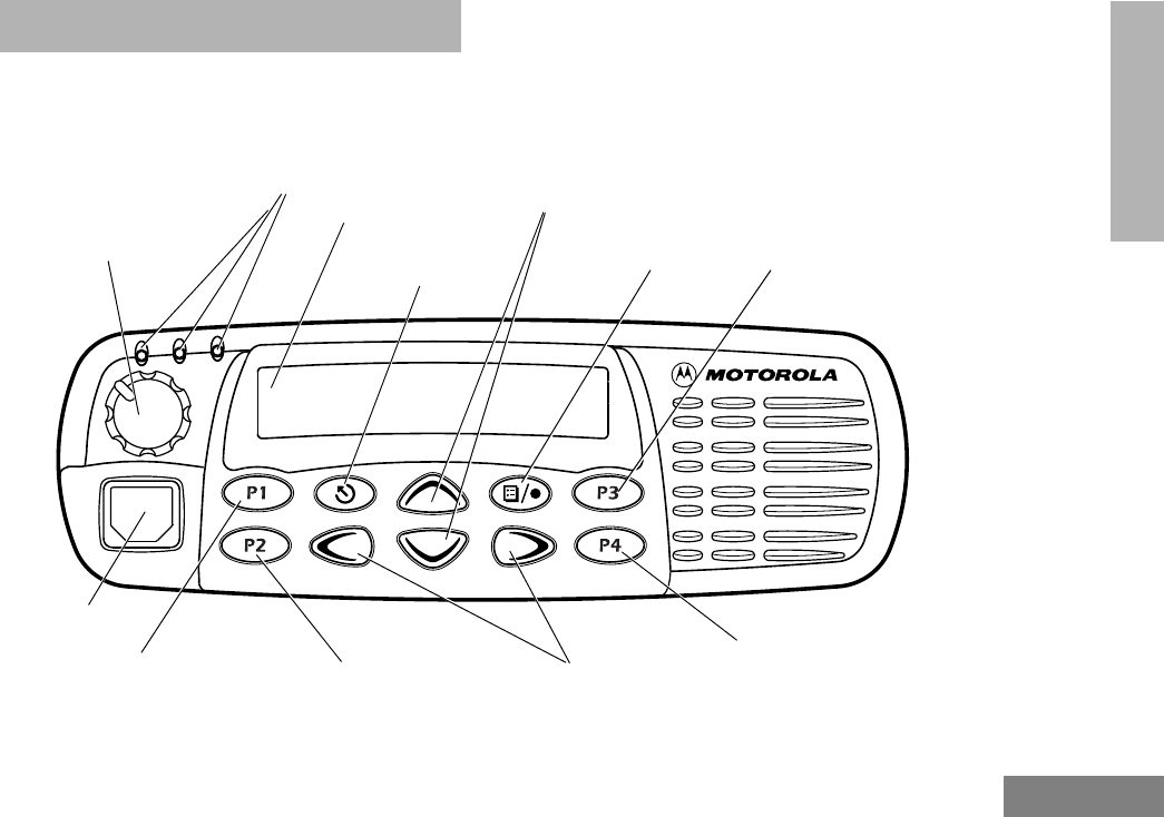
PARTS OF THE RADIO
CDM1550•LS+ Model
Zone Selector/
Editing Buttons
Menu Enter/Select
Button
(Interchangeable)
Programmable
Button 2 (P2) (Interchangeable)
Programmable
Button 4 (P4)
(Interchangeable)
Programmable
Button 3 (P3)
LCD Screen
Red/Yellow/Green
LED Indicators
Menu Exit/Escape
Button
(Interchangeable)
Programmable
Button 1 (P1)
(Left/Right)
Microphone
Jack
Control Knob
On/Off/Volume
Talkgroup/Channel Selector/
Menu Navigation Buttons
(Up/Down)
03_Radio Overview.fm Page 17 Tuesday, April 2, 2002 5:48 PM

18
English
RADIO OVERVIEW
On/Off/Volume Control Knob
Turns the radio on or off, and adjusts the
radio’s volume.
LED Indicators
Indicates power-up, scan, or receipt of a
talkgroup or selective call (see table below):
• Used to scroll through the preprogrammed
trunked and conventional zones.
• Used to scroll through menu choices when
in Menu Mode.
• When editing Call, Scan, and Phone lists,
v is used as a backspace key and w is
used to add a space.
• Used to scroll through the preprogrammed
talkgroups of a selected trunked zone, or
through conventional channels when in
conventional zone.
• Used to scroll through menu choices when
in Menu Mode.
LED Color Indicates
Steady red Radio is transmitting (PTT button
pressed)
Flashing red Radio is attempting to access
trunked system (PTT button
pressed), or
Radio is receiving (PTT button
released)
Double
flashing yellow Call Light feature, or
Individual Selective Call
Received
Single flashing
yellow Group Selective call received
(LTR trunked and conventional
operation only)
Momentary
green Radio has powered-up
successfully
Double
flashing green System, All Group Scan or
PassPort Group Scan Operation
LED Color Indicates
Left Button v and Right Button w
Up Button y and Down Button z
03_Radio Overview.fm Page 18 Tuesday, April 2, 2002 5:48 PM

19
English
RADIO OVERVIEW
Push-to-Talk (PTT) Button
Press and hold down this button to talk;
release it to listen.
Microphone
When sending a message, hold the
microphone 1 to 2 inches (2.5 to 5 cm) away
from your mouth, and speak clearly into the
microphone.
Menu/Select Button )
Used to enter Menu Mode. When in Menu
Mode, this button is used to make menu
selections.
Menu Exit/Button (
Used to move to the previous Menu level (short
press) or to exit Menu Mode (long press).
Menu Buttons
Exit Up Menu/
Select
Left Down Right
03_Radio Overview.fm Page 19 Tuesday, April 2, 2002 5:48 PM
20
English
RADIO OVERVIEW
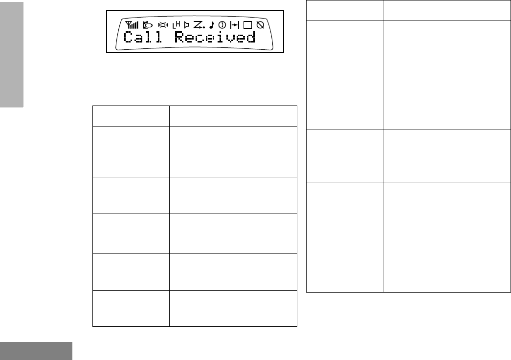
Display
The top display row displays menu and radio
status information:
Symbol Indication
A
X-Pand
The X-Pand feature is
activated. When in narrow
band, this feature improves
audio quality.
B
Power Level
Low Power “ R ” or High
Power “ S ” is activated.
C
Monitor
The selected channel is being
monitored (conventional
operation only).
D
Phone
Phone mode is selected.
F
Call Received
A Selective Call or Call Alert
has been received .
G
Scan
When the green LED is
blinking, indicates that the
System, PassPort Scan, or All
Group Scan feature has been
activated.
When the green LED is off,
indicates that non-prioritized
Auto Group Scan has been
activated.
H
•Priority 1 Scan
( • flashing)
Indicates activity on a priority
1 talkgroup or channel during
System Scan.
H
Priority 2 Scan
( • steady)
• When the green LED is on,
indicates activity on a
priority 2 talkgroup or
channel during System
Scan.
• When the green LED is off,
indicates prioritized Auto
Group Scan has been
activated.
Symbol Indication
03_Radio Overview.fm Page 20 Tuesday, April 2, 2002 5:48 PM
21
English
RADIO OVERVIEW
Microphone Jack
Plug the optional DTMF Microphone
(RMN4026) or other microphone into this jack.
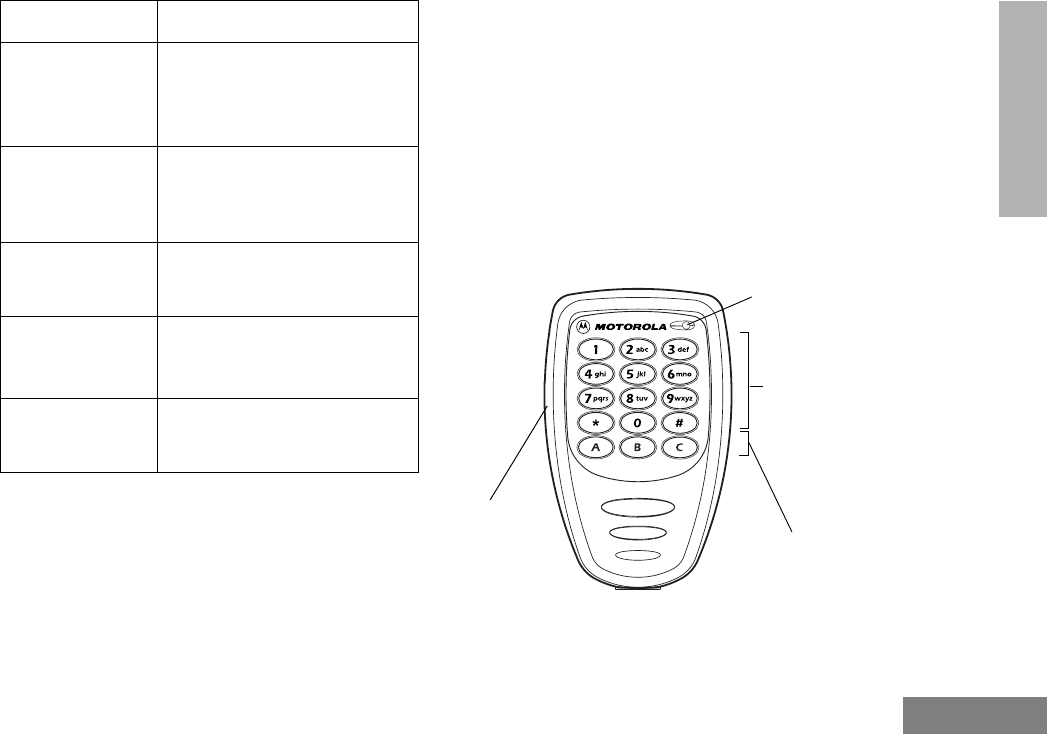
OPTIONAL DTMF MICROPHONE
(RMN4026)
Your radio may be ordered with an optional
DTMF (Dual-Tone Multi-Frequency)
microphone that has a direct-entry keypad.
This microphone has three buttons (A, B, C)
below the keypad that can be programmed by
your dealer to conveniently activate available
radio features.
J
Talkaround
You are not transmitting
through a repeater
(Conventional operation
only).
K
Programming
Mode
A Program list is being edited.
U
Clock
Shows the time (12- or
24-hour).
M
Signal Strength
The more bars, the stronger
the signal being received by
your radio.
N
PassPort Zone
A PassPort zone has been
selected.
Symbol Indication
Keypad
Push-to-Talk
(PTT) Button Programmable
Buttons
(A, B, C)
Microphone
03_Radio Overview.fm Page 21 Tuesday, April 2, 2002 5:48 PM

22
English
RADIO OVERVIEW
DTMF Microphone Keypad
The keypad is used for:
• Dialing a phone number
• Entering a specific radio ID number when
making an MDC radio call
• Entering information when programming
radio call, scan, and phone lists.
• Directly accessing preprogrammed features
( , , and buttons [see
page 24])
Each key can generate several different
characters. For example, to enter the character
“C,” press the 2 button three times. (Refer
to the following table on page 23.)
123
456
789
*0#
***
A B C
03_Radio Overview.fm Page 22 Tuesday, April 2, 2002 5:48 PM

23
English
RADIO OVERVIEW
Entering Characters Using the DTMF Microphone Keypad
Number of Times Button is Pressed
Button 1 23 4 5 6 7 8 9 101112131415
00()<>
11&%# *
2ABC2abc2 Á Ç à á ç
3DEF3def 3 È É Ê è é ê
4GHI4ghi4 Í ì í
5JKL5 j kl 5
6MNO6mno6 Ñ ÓÔ ò ó ô ö
7PQRS7 pq r s 7
8TUV8 t uv8 Ú ù ú
9WXYZ9wx y z 9 Y y
**/+-=
##Blank
Space -.!?’” , ; :
03_Radio Overview.fm Page 23 Tuesday, April 2, 2002 5:48 PM

24
English
RADIO OVERVIEW
PROGRAMMABLE BUTTONS
Your radio has several programmable buttons
that can be programmed by your dealer as
shortcuts to various radios’ features.
Programmable buttons include:
• The four front buttons (P1, P2, P3, and P4).
• The three buttons (A. B, and C) of the
optional DTMF microphone.
Some buttons can access up to two features,
depending on the type of button press:
•Short Press—quickly pressing and
releasing the programmable buttons,
or
•Long Press—pressing and holding the
programmable buttons,
or
•Hold Down—pressing and holding down
the programmable buttons while checking
status or making adjustments.
The table on page 25 summarizes the
programmable features available and shows
the page number where the feature is
explained.
In the “Button” column, have your dealer record
the name of the programmable button next to
the feature that has been programmed to
them.
Use the abbreviations for instance P1, P2, P3,
and P4 shown in the radio illustrations at the
front of this manual.
Also, where a choice exists, have your dealer
indicate whether the button press is short
press (SP), or long press (LP).
Check with your dealer for a complete list of
features your radio supports.
03_Radio Overview.fm Page 24 Tuesday, April 2, 2002 5:48 PM

25
English
RADIO OVERVIEW
Programmable Features
Feature Indicator Short Press Long Press Hold Down Page Button
Home Channel — Directly access your favorite trunked zone
and talkgroup or conventional channel.†—35
Backlight
Control —Turn on your radio backlight.†——
Monitor §CEnter/Exit perma-
nent monitor mode. Open Squelch. Continually monitor
channel. —
Phone DDirectly access Phone mode.†—71
Power Level BToggle transmit power level between high
and low.† —93
Radio Call LED
Color Directly access radio call menu.†—47
Repeater/
Talkaround §J
Toggle between using a conventional
repeater or transmitting directly to another
radio.†
—34
Roam Request*Searching Manually initiate
PassPort roaming
function.
Stop PassPort
roaming function. —42
Scan/Delete
Nuisance
Channel
G
Turn PassPort
Group, All Group,
and System scan
on or off.
Delete a nuisance
channel while
scanning. —66
† This feature is activated by EITHER a short OR a long press, but not both.
§ Conventional operation only. ‡LTR trunked operation only. *PassPort trunked operation only.
03_Radio Overview.fm Page 25 Tuesday, April 2, 2002 5:48 PM

26
English
RADIO OVERVIEW
Site/MIN View*—Displays the PassPort site number on
which the unit is registered, the home site
and unit’s MIN (Mobile Identity Number).† —41
Speed Dial —Quickly access speed dial phone list.†—71
Voice Storage
Record/Playback —Playback recorded
messages. Record voice
memos. —82
Voice Storage
Playback Exit —Exit Voice Storage Play Back mode.†—83
Voice Storage
Playback Delete —Delete recorded messages.†—84
Volume Set —— —
Sound a tone for
adjusting your
radio’s volume level. 29
Edit Scan List —Add, delete, or prioritize talkgroups or
channels. 66
Direct Zone
Access —Direct entry to zone selection menu.†—31
† This feature is activated by EITHER a short OR a long press, but not both.
§ Conventional operation only. ‡ LTR trunked operation only. *PassPort trunked operation only.
Programmable Features (Continued)
Feature Indicator Short Press Long Press Hold Down Page Button
03_Radio Overview.fm Page 26 Tuesday, April 2, 2002 5:48 PM

27
English
RADIO OVERVIEW
Direct Channel
Access —Direct access to a trunked talkgroup or
conventional channel through a Smart
Microphone †—31
Horn and Lights — Toggles external alarm feature or cancels
a triggered alarm.†—35
Auxiliary
Control (1/2) —Activates or deactivates a pin on the
accessory connector.†——
Status§— Direct entry to the message menu.†—50
Message§— Direct entry to the message menu.†—51
Emergency§EInitiate
Emergency Alert Cancel Emergency
Alert —56
† This feature is activated by EITHER a short OR a long press, but not both.
§ Conventional operation only. ‡ LTR trunked operation only. *PassPort trunked operation only.
Programmable Features (Continued)
Feature Indicator Short Press Long Press Hold Down Page Button
03_Radio Overview.fm Page 27 Tuesday, April 2, 2002 5:48 PM

28
English
RADIO OVERVIEW
Audio Indicators for Programmable Buttons
In addition to having visual indicators, some
programmable buttons use tones to indicate
one of two modes:
High-Low Tone
Low-High Tone
Button High-Low Tone Low-High Tone
Scan Stop scan Start scan
Power Level High power
selected Low power
selected
Repeater/
Talkaround
Uses
conventional
repeater
Does not use
conventional
repeater
03_Radio Overview.fm Page 28 Tuesday, April 2, 2002 5:48 PM

29
English
GETTING STARTED
GETTING STARTED
TURNING THE RADIO ON OR OFF
ADJUSTING THE VOLUME
Turn the On/Off/Volume Control knob
clockwise to increase the volume, or
counterclockwise to decrease the volume.
–or–
ON OFF
Push the On/Off/
Volume Control knob.
If power-up is
successful, you hear
the Self-Test Pass Tone
and see the LED
momentarily turn
green.
If the radio fails to
power up, you hear the
Self-Test Fail
Tone .
Push the On/Off/
Volume Control knob
until you hear a click and
the display clears.
1Hold down the Volume Set button (see
page 26). You hear a continuous tone.
2Turn the On/Off/Volume Control knob to
the desired volume level.
3Release the Volume Set button.
Control Knob
On/Off/Volume
04_GetStarted.fm Page 29 Tuesday, April 2, 2002 4:38 PM

30
English
GETTING STARTED
SELECTING A TRUNKED ZONE
AND TALKGROUP
Up to 15 PassPort and/or LTR trunked zones
(containing 16 talkgroups each) can be
programmed into your radio.
To select a trunked zone and talkgroup:
SENDING A TRUNKED CALL
To Send a Trunked Call
Note: Throughout this manual there are
features listed as trunked and con-
ventional. Trunked indicates the fea-
ture functions in both PassPort and
LTR zones unless otherwise noted.
Conventional indicates the feature
functions in Conventional zones
only.
1v or w to select the appropriate
trunked zone.
2y or z until you see the desired
preprogrammed talkgroup on the display.
Note: N (the PassPort Zone symbol)
appears when a PassPort Zone has
been selected.
1Hold the microphone in a vertical position
at a distance of about 1 to 2 inches (2.5
to 5 cm) from your mouth.
2Press and hold the PTT button.
–or–
Press and release the PTT button and
wait 3 seconds.
• If access to the trunked system was
successful, the red LED indicator
lights steady.
- In addition, your dealer can
program your radio to sound a
short, high-pitched (talk permit)
tone, indicating successful trunked
system access.
• If access to the trunked system was
unsuccessful, the red LED indicator
flashes and a low-pitched (talk
prohibit) tone sounds, indicating that
the system was busy or out-of-range.
04_GetStarted.fm Page 30 Tuesday, April 2, 2002 4:38 PM

31
English
GETTING STARTED
SELECTING A CONVENTIONAL
ZONE AND CHANNEL
Up to a total of 16 conventional channels, in
one or more conventional zones, can be
programmed into your radio.
To Select a Conventional Zone and Channel
DIRECT ZONE ACCESS
The Direct Zone Access feature offers an
alternative way of accessing a trunked or
conventional zone.
To Activate Direct Zone Access
DIRECT CHANNEL ACCESS
The direct channel access feature allows you
to directly access a specific trunked talkgroup
or conventional channel within the zone you
have currently selected. This feature can be
programmed on one of the radio
programmable buttons (P1, P2, P3 or P4) and/
or any DTMF microphone (RMN4026)
programmable buttons (A, B or C).
3With the PTT button depressed, speak
clearly into the microphone
4Release the PTT button to listen.
1v or w to select the appropriate
conventional zone.
2y or z until you see the desired
conventional channel on the display.
1Press the preprogrammed Direct Zone
Access button (see page 27).
2y or z until you see the desired
zone on the display.
3u to confirm your selection.
04_GetStarted.fm Page 31 Tuesday, April 2, 2002 4:38 PM

32
English
GETTING STARTED
To Start Activate Direct Channel Access
Using the radio’s programmable buttons:
Using the DTMF microphone:
1Press the preprogrammed Direct
Channel button.
The current talkgroup or channel flashes
intermittently.
2Up or down arrow y or z to select
the appropriate Trunked talkgroup or
channel.
3Press again the preprogrammed Direct
Channel button.
–or–
Press y or z
The new selected talkgroup or channel
appears on the display
YR TKGP ALIAS
NW TKGP ALIAS
1Press the preprogrammed Direct Channel
button (A, B, or C).
The current talkgroup or channel flashes
intermittently.
2 Up or down arrow y or z to select the
appropriate Trunked talkgroup or channel.
–or–
If Menu/Channel Up feature is
preprogrammed on the DTMF microphone
press it to select the appropriate talkgroup or
channel.
3Press again the preprogrammed Direct
Channel button.
–or–
Press select/enter button on the micro-
phone (if preprogrammed).
The new selected talkgroup or channel
appears on the display.
YR TKGP ALIAS
NW TKGP ALIAS
04_GetStarted.fm Page 32 Tuesday, April 2, 2002 4:38 PM

33
English
GETTING STARTED
SENDING A CONVENTIONAL CALL
Note: In the United States, FCC regulations
require you to monitor the conventional
channels before sending a call. The
monitor feature (see page 25) can be
accessed through one of your
programmable buttons.
To send a conventional call:
RECEIVING A TRUNKED OR
CONVENTIONAL CALL
1Hold the microphone in a vertical position
at a distance of about 1 to 2 inches (2.5
to 5 cm) from your mouth.
2Press the PTT button and speak clearly
into the microphone. The red LED indica-
tor lights steady while the call is being
sent.
3Release the PTT button to listen.
1Turn your radio on.
2Adjust your radio’s volume (see page 29).
3v or w to select the desired trunked
or conventional zone, then y or z
until you see the desired preprogrammed
talkgroup or conventional channel on the
display.
• Make sure the PTT button is released.
4Listen for voice activity. The red LED indi-
cator flashes when your radio is receiv-
ing.
Note: In PassPort mode, the Mobile
Identity Number (XXXX) of the
calling radio appears on the display
if enabled. XXXX
04_GetStarted.fm Page 33 Tuesday, April 2, 2002 4:38 PM

34
English
GETTING STARTED
REPEATER OR TALKAROUND J
MODE
(CONVENTIONAL OPERATION ONLY)
Talkaround Mode enables you to communicate
with another radio when either:
• The repeater is not operating
–or–
• Your radio is out of the repeater’s range but
within communicating distance of another
radio.
Note: The J symbol appears on the LCD
screen when Talkaround Mode is
selected.
To Select either Repeater Mode or
Talkaround Mode
Press the preprogrammed Repeater/
Talkaround button (see page 25) to toggle
between Repeater Mode and Talkaround Mode.
–or–
1) to enter Menu Mode.
2y or z until
3) to select
4y or z until
–or–
5) to confirm your selection.
Rptr/Talkarnd
Rptr/Talkarnd
Talkarnd Mode
Talkarnd Mode
04_GetStarted.fm Page 34 Tuesday, April 2, 2002 4:38 PM

35
English
GETTING STARTED
CALL LIGHT
(TRUNKED OPERATION ONLY)
The Call Light indicator informs you that you
have received a call from a specified talkgroup
(as programmed by your dealer). The yellow
LED indicator flashes continuously, indicating
that a call has been received.
To Turn the Call Light Off
• Turn the radio off, then on again.
• Select another trunked or conventional
zone.
• Press the PTT button.
• Press any preprogrammed button.
HOME CHANNEL
The Home Channel feature allows you to
instantly access your favorite trunked talkgroup
or channel at the touch of a button.
To Activate Home Channel
Press the preprogrammed Home Channel
button (see page 25).
HORN AND LIGHTS
When you are away from your vehicle, the
Horn and Lights feature notifies you when a
call is received by activating your vehicle’s horn
and lights. This feature can be triggered by a
call alert in LTR mode. It also can be
associated with call light in LTR and PassPort
mode.
To Activate Horn and Lights Programmed
with Call Light (Trunked Operation Only)
1Press the preprogrammed Horn and
Lights button. The LED flashes yellow
continuously, indicating that a call has
been received.
you see
2Once the delay timer has expired, the
horn and lights of the vehicle go off.
3Press any buttons on the radio or the
DTMF microphone to deactivate it.
YR CURRENT TKGP
04_GetStarted.fm Page 35 Tuesday, April 2, 2002 4:38 PM

36
English
GETTING STARTED
To Activate Horn and Lights Programmed
with Call Alert
(LTR Trunked Operation Only)
REMOTE MONITOR
(LTR TRUNKED AND CONVENTIONAL
OPERATION ONLY)
Remote Monitor allows you to automatically
key-up another radio to listen-in on all
surrounding audio. This feature can be initiated
by a dispatcher to a mobile radio, or from a
mobile radio to another mobile radio.
To Activate Remote Monitor
1Press the preprogrammed Horn and
Lights button. When you receive a call
alert, you can see the preprogrammed
name or ID of the calling radio:
Note: If preprogrammed, alert tones (either
once or continuously) may sound.
2Press any buttons on the radio or the
DTMF microphone to deactivate it.
Note: There are options available in the
CPS (Customer Programming
Software), which don’t require you
to manually activate Horn and
Lights. Please see your dealer for
additional information.
YOUR NAME OR ID
1) to enter Menu Mode.
2y or z until
3) to select
4y or z until
5) to select the appropriate call list
member:
Note: An audio or visual indication may
come up on the receiving radio if
preprogrammed by your dealer.
Radio Call
Radio Call
Remote Monitor
MDC CALL 01
04_GetStarted.fm Page 36 Tuesday, April 2, 2002 4:38 PM

37
English
GETTING STARTED
To cancel Remote Monitor, press any
button on the radio.
Note: Remote monitor automatically
ceases after one transmit and one
receive cycle.
04_GetStarted.fm Page 37 Tuesday, April 2, 2002 4:38 PM

38
English
GETTING STARTED
Notes
04_GetStarted.fm Page 38 Tuesday, April 2, 2002 4:38 PM

39
English
PASSPORT
TRUNKING
PASSPORT TRUNKING
PassPort is an enhanced, wide-area trunking
protocol developed by Trident Micro Systems.
Up to 128 trunked sites can be linked together
to form one PassPort system, which means
that your communications can extend far
beyond the reach of a single trunked site.
SEAMLESS ROAMING
PassPort Trunking systems offer you the ability
to seamlessly roam among all sites in a
network. Seamless Roaming means that you
do not have to manually change the zones on
the radio when roaming from site-to-site. As
you roam throughout a PassPort System’s
coverage area, your CDM1550•LS+ radio is
regularly monitoring the RSSI (Received
Signal Strength Indication) level of the site on
which you are currently registered. In addition,
if the signal strength falls below the acceptable
threshold pre-programmed by your dealer, your
radio starts monitoring the RSSI level of
adjacent sites within the network. This allows
the CDM1550•LS+ radio to quickly roam to the
site with the strongest signal, which provides
you with optimal audio quality throughout your
communications.
Initial Registration
Before communications with your talkgroup
can begin, your radio needs to register on the
PassPort system. Registration automatically
takes place upon radio power up or after
selecting the desired PassPort zone on the
selector knob. What you see:
1Upon radio Power up, you see:
(if you select a PassPort zone after the
radio is powered up, see step 2).
2The selected PassPort zone alias
appears on the display.
3The selected Talkgroup Alias appears
on the display.
PASSPORT
YOUR ZONE ALIAS
TLKGRP ALIAS

40
English
PASSPORT
TRUNKING
Roaming and Registering Between Sites
Once initial registration with the PassPort
system has occurred, your radio constantly
monitors the RSSI to ensure an acceptable
signal level is maintained (as programmed by
your dealer). When the RSSI in the radio falls
below this acceptable level, the CDM1550•LS+
attempts to roam to and register onto another
site within the PassPort system.
This process happens automatically and
requires no action by you. What you see:
Note: If the radio performs a more
extensive frequency search in order to
attempt successful registration, you may see
on the display:
4Upon successful PassPort Registration,
you see:
Note: Your radio sounds a “Low-High” tone
upon successful PassPort System registra-
tion. The XXX number indicates the site within
the PassPort system on which you have regis-
tered.
5
After successfully registering at a site,
the selected PassPort talkgroup alias
appears and remains on the display.
SEARCHING
REG SITE XXX
TLKGRP ALIAS
1When the radio is searching for a new
site or attempting successful registration
to a site, you see on the display:
Note: This message is displayed until suc-
cessful registration.
2When the radio has successfully regis-
tered to the new PassPort System, XXX
indicates the site number you see on the
display.
SEARCHING
REG SITE XXX

41
English
PASSPORT
TRUNKING
SITE/MIN VIEW
There may be circumstances when you want to
view the number of the PassPort site on which
you are registered as well as your Mobile
Identity Number (MIN).
To Start And Stop Viewing Site/Min
3The selected PassPort talkgroup alias
appears and remains on the display.
1Press the preprogrammed SITE/MIN
View button (see page 26).
The display shows the number of the site
on which you are currently registered.
Note: If the preprogrammed button is acti-
vated prior to or during registration, a bad key
chirp is sounded and you see on the display:
TLKGRP ALIAS
site now XXX
site now n/a
The display indicates the Home Site
Number (HSID) and Mobile Identity
Number.
XXX indicates the HSID, YYYYY indi-
cates the MIN.
Note: This message can be activated if the
radio is not registered.
IAM XXX-YYYYY

42
English
PASSPORT
TRUNKING
ROAM REQUEST
Because of the RSSI feature, the
CDM1550•LS+ radio automatically roams to a
different site when the signal from the
registered site becomes too weak for quality
communication. This RSSI threshold is
programmed by your dealer. However, if you
believe the signal strength would be better on
another site, you may want to manually initiate
the roaming process. This feature is called
Roam Request.
To Start a Roam Request
1Press the preprogrammed Roam
Request button (see page 25).
2When the radio is searching for a new
site or attempting successful registration
to a site, you see on the display:
SEARCHING
3When the radio has successfully regis-
tered to the new PassPort System, you
see on the display:
Note: A bad key chirp may sound and you
see on the display:
• When registration to a site with a
higher RSSI than your current site is
unavailable.
• When the preprogrammed button is
pressed before the radio has collected
its “neighbor list”. A Neighbor list” is a
list of frequencies from adjoining sites
within the PassPort system that are
used during the roam process.
• When the radio is programmed for a
single home system.
In these cases, wait a few seconds and
try again.
REG SITE XXX
Roam Not Avail

43
English
PASSPORT
TRUNKING
To Cancel a Roam Request
TROUBLESHOOTING
While in PassPort zones, there are some
specific display messages that indicate you
should contact your dealer for assistance.
4The selected PassPort talkgroup alias
appears and remains on the display:
1Press and hold the preprogrammed
Roam Request button (see page 25)
again.
You see:
Note: The radio then attempts to return to
the previously registered site.
TLKGRP ALIAS
Cncl Roam Req
Message What it Means
“Invalid Group ID” Your dealer needs to verify talk-
group programming in your
radio or the PassPort system.
“DISABLED” Your radio requires reactivation
on the PassPort system (not
applicable to conventional and
LTR functionality).
Blank display
upon power up . Your radio needs to be returned
to your dealer for reactivation or
service.

44
English
PASSPORT
TRUNKING
Notes:

45
English
RADIO CALLS
RADIO CALLS
MAKING A SELECTIVE CALL
(LTR TRUNKED AND CONVENTIONAL
OPERATION ONLY)
You can make a selective call to a particular
radio or to a group of radios, as programmed
by your dealer.
To Make a Selective Call
Press the preprogrammed Radio Call button
(see page 25), and proceed to step 4.
–or–
1) to enter menu mode.
2y or z until
3) to select
4y or z until
5) to select
Radio Call
Radio Call
Selective Call
Selective Call
6y or z to locate the desired ID in
the Radio Call List.
–or–
Enter with the DTMF microphone the ID
number of the radio you want to call.
7Press the PTT button to send the call.
• The radio sounds a continuous tone, if
programmed by your dealer.
• The LED lights a solid yellow.
8Press the PTT button and talk; release
the PTT button to listen.
If not received, you see:
9( t o re t u r n t o
–or–
Hold down ( to exit menu mode.
No Acknowledge
Selective Call

46
English
RADIO CALLS
RECEIVING A SELECTIVE CALL F
(LTR TRUNKED AND CONVENTIONAL
OPERATION ONLY)
When you Receive a Selective Call
• The display shows F and the prepro-
grammed name or ID of the calling radio.
• The LED indicator flashes yellow, if pro-
grammed by your dealer.
• You hear an alert tone.
To answer the call, press the PTT button.
Note: Unless you make a Selective Call back to
the caller, your response is heard by all
members of your talkgroup.
SENDING A CALL ALERT PAGE
(LTR TRUNKED AND CONVENTIONAL
OPERATION ONLY)
You can alert another person by sending a Call
Alert page.
To Send a Call Alert Page
Press the preprogrammed Radio Call button
(see page 25) and proceed to step 4:
1) to enter menu mode.
2y or z until
3) to select
4y or z until
5) to select
6y or z to locate the desired ID in
the Radio Call List.
–or–
Enter with the DTMFmicrophone the ID
number of the radio you want to page.
7Press the PTT button,
Radio Call
Radio Call
Call Alert
Call Alert

47
English
RADIO CALLS
RECEIVING A CALL ALERT PAGE
(LTR TRUNKED AND CONVENTIONAL
OPERATION ONLY)
When You Receive a Call Alert Page
• The display shows F
and the preprogrammed name or ID of the
calling radio.
• You hear four alert tones, either once or
continuously, as programmed by your
dealer.
• The LED indicator flashes a single yellow
for a group call, or flashes a double yellow
for an individual call.
To answer the page, press the PTT button; to
cancel the page, press any other button.
Note: Your radio displays only the last Call Alert
page received. Also, your radio does not
receive any Selective Calls until you clear
the page.
you see:
and the preprogrammed name or ID
alternating on the display.
• The LED alternates between a solid
yellow and solid red while the call is in
process.
8If the Call Alert page is received by the
target radio, you see:
If not received,
you see:
• The radio sounds a short alert tone if,
programmed by your dealer.
9( to return to
–or–
Hold down ( to exit menu mode.
Call in Prog
Acknowledge
No Acknowledge
Call Alert
Call Received
48
English
RADIO CALLS
RADIO CHECK
(LTR TRUNKED AND CONVENTIONAL
OPERATION ONLY)
Radio Check allows you to determine if a radio
is within the range of the trunked system and
turned on, without disturbing the user of that
radio. This feature can also be used when
attempts with Selective Call and Call Alert fail.
To Perform a Radio Check
SENDING A STATUS
(CONVENTIONAL OPERATION ONLY)
This feature gives you the ability to send a
status update to the base. The status feature
makes more efficient use of the channel
compared to voice transmissions. Status
updates of up to 14 characters may be
programmed by your dealer.
1) to enter menu mode.
2y or z until
3) to select
4y or z until
5) to select
6y or z to locate the desired ID in
the Radio Call list
–or–
Enter the ID number of the radio you are
checking.
Radio Call
Radio Call
Radio Check
Radio Check
7Press the PTT button,
you see:
8If the Radio Check is received by the tar-
get radio, you see:
If not received, you see:
9( to return to
–or–
Hold down ( to exit menu mode.
Call In Prog
Acknowledge
No Acknowledge
Radio Call

49
English
RADIO CALLS
To Send a Status SENDING A MESSAGE
(CONVENTIONAL OPERATION ONLY)
This feature gives you the ability to send and
receive preprogrammed messages. Data
messages make more efficient use of channels
compared to voice transmissions. Messages of
up to 14 characters may be programmed by
your dealer.
To Send an Electronic (Data) Message
1) to enter Menu Mode.
2y or z until
3) to select
4y or z to locate the desired status in
the preprogrammed list.
–or–
when using the enhanced keypad
microphone only,
enter the number of the status you wish
to send.
–or–
if programmed by your dealer (see page
27),
press the button that has been
preprogrammed for a specific status.
Note: You cannot retransmit the current
status update.
Status
Status
1) to enter Menu Mode.
2y or z until
3) to select
Message
Message

50
English
RADIO CALLS
RECEIVING A MESSAGE
(CONVENTIONAL OPERATION ONLY)
When your radio receives a message:
• You hear two alert tones.
• The yellow LED indicator flashes.
• You see:
alternating with the preprogrammed alias.
Note: If you receive a message that is
programmed into your radio, the display will
alternate with the following:
and
RESPONDING TO EMERGENCY
ALERTS E
(CONVENTIONAL OPERATION ONLY)
Your radio offers choices for initiating and
responding to Emergency Alert
communications. Choices may include:
• Emergency Cycles - Allows the radio to
automatically cycle between transmit and
receive mode over a preprogrammed
number of times by keying with voice after it
4y or z to locate the desired message
in the preprogrammed list.
–or–
when using the enhanced keypad
microphone only,
enter the number of the message you
wish to send.
–or–
if programmed by your dealer (see page
27),
press the button that has been
preprogrammed for a specific message.
Msg Received
Message #_
No Alias

51
English
RADIO CALLS
has received an Acknowledge to the alarm
you send. The default number of transmits
is one (10, maximum); the default value of
the retransmit interval is 5 seconds (one,
minimum; 60, maximum).
• Emergency Alarm/Call - Gives you access
to a voice resource, on a priority basis, over
all other types of call traffic.
• Emergency Remote Monitor - Enables the
dispatcher to activate the transmit circuit of
your radio, during an Emergency, to hear
the situation through your microphone. See
page 53 for more about sending an
Emergency Remote Monitor.
• Remote Monitor - Enables the dispatcher to
activate the transmit circuit of your radio,
during a normal dispatch, to hear the
situation through your microphone. See
page 54 for information about sending a
Remote Monitor.
Note: All the choices listed above are dealer
preprogrammed. See your dealer for more
details.
Decoding an Emergency Alarm
If preprogrammed by your dealer, and provided
the signaling protocol supports it, your radio
decodes (responds to) an Emergency Alarm or
Emergency Call by:
• Sounding a unique, repeating alert tone
• Activating an external alarm
• Displaying alternating message parts on a
single line, similar to the following example
•the word Emergency, followed by
• Emergency Alias from the Radio Call List
(example, MDC CALL 01), followed by
E
Emergency
E
MDC CALL 01

52
English
RADIO CALLS
• Timestamp of the Emergency Alert (exam-
ple, 03:55).
• Flashing the E icon (while decoding only;
lights steady when encoding)
Multiple Queued Emergencies
Clearing the existing displayed Emergency
shows the next in the queue, if one exists.The
display updates and shows “Emerg (queued
number) of (total number)”. If no additional
Emergencies are queued, the radio exits
Emergency mode and resumes normal mode.
Three Minute Timer
Responding to an Emergency starts a three-
minute timer. The radio does not generate
another Emergency Alert tone against that
Emergency Alias or ID until the three-minute
period expires. If cleared within 3 minutes, the
alarm will regenerate the alert. If the radio
receives another Emergency Alert from the
same Alias or ID, the radio acknowledges the
Emergency but does not restart the tone,
activate the external alarm, or display updated
information.
After the Timer Expires
If the three-minute timer has expired for a
specific Emergency Alias or ID, and the radio
decodes an Emergency that is currently in
queue, the radio:
• Acknowledges the Emergency
• Restarts the Emergency Alert tone
• Activates the external alarm
• Updates the time stamp on the matching
Emergency
Note: If the Radio Call List does not include an
alias for the radio ID, the ID displays. Radios
that do not support the signaling protocol
sound the alert tone, activate the external
alarm and display data.
E
03:55

53
English
RADIO CALLS
CLEARING AN EMERGENCY
ALERT E
(CONVENTIONAL OPERATION ONLY)
To Clear an Emergency Alert
SENDING AN EMERGENCY
REMOTE MONITOR
(CONVENTIONAL OPERATION ONLY)
As your radio responds to an Emergency Alert,
only the Emergency Queue menu is available.
To access the Emergency Queue menu:
1Press any button on the radio to
cancel the Emergency Alert tone.
2Press (or activate) an external
pushbutton or foot switch.
Note: You must press an external switch to clear
the visible Emergency Alias and display the
next queued Emergency Alias, if present.
You must clear all decoded Emergency
Alerts before encoding (sending) your own
Emergency Alert.
1) to enter Menu Mode.
2The radio
displays the list
of aliases
currently in the
Emergency
queue, similar to
that shown,
oldest to newest.
3z or y to view the next oldest
Emergency Remote Monitor packet and
to choose the packet to send.
4Press the PTT to send the packet.
MDC CALL 01

54
English
RADIO CALLS
SENDING AN EMERGENCY
ALERT E
(CONVENTIONAL OPERATION ONLY)
A priority Emergency Alert can be sent to a
specific radio or dispatch center by pressing:
• A button preprogrammed by your dealer
(see page 27).
• The foot switch
• A pushbutton accessory
Emergency Alerts have priority over all other
calls.
The E symbol will appear on the display when
your radio is in the Emergency Alert state.
An Emergency Alert can be programmed to:
•Show E and sound a tone
–or–
• Show the normal display
–or–
• Activate the microphone so that all activity
can be transmitted (for a predetermined
amount of time). See your dealer for more
information.
To cancel the Emergency Alert, press and hold
down the preprogrammed Emergency button.
SENDING A REMOTE MONITOR
The Remote Monitor gives the ability to
activate the transmit circuit of your radio – both
silently and normally – and key it. The Remote
Monitor feature depends on how your radio
responds to the Remote Monitor Command.
Upon receiving a Remote Monitor Command,
the radio:
1. Keys the transmitter.
2. Acknowledges the command
3. Sends the PTT-ID
4. Activates the microphone.
Note: If a remote microphone is attached, it
responds.
Remote Monitor capability depends on which
of two modes are preprogrammed:
• Silent Mode – When the command is sent in
Silent Mode, and the receiving radio keys
and transmits for the time set by the Remote
Monitor Command, the receiving radio will
not generate an indicator of the event.
• Non-Silent Mode – When the command is
sent in Non-Silent Mode, and the receiving
radio keys and transmits for the time set by

55
English
RADIO CALLS
the Remote Monitor Command, the receiv-
ing radio will generate an indicator of the
event.
The amount of time that the radio remains in
receive mode or in transmit mode is set by the
Remote Monitor Command and the time
settings in the radio. When in this state,
touching any button on the radio takes it out of
the Remote Monitor mode. See your dealer for
more details.
SELECTIVE RADIO INHIBIT
(CONVENTIONAL OPERATION ONLY)
Your radio is equipped with a security feature
that can temporarily render the unit inoperative
when an inhibit signal is sent from the base
station.
This feature is commonly used to disable radios:
• In case of theft
• When your vehicle is being serviced
• For system control reasons
Note: When your radio has been disabled by the
base station, all controls will be inoperative
except for the On/Off button. When the radio
is powered up,
You see:
EDITING A RADIO CALL LIST K
(LTR TRUNKED AND CONVENTIONAL
OPERATION ONLY)
Your radio has a Radio Call list that contains
the names and radio IDs of several talkgroups
or individuals. The ID numbers in the Radio
Call List are programmed by your dealer, and
cannot be changed from your radio. However,
you can edit the names associated with these
IDs. The K symbol appears on the display
when you are editing.
Note: The radio cannot receive any calls while
you are editing.
To Edit a Call List Entry
1) to enter menu mode.
2y or z until
Radio Disabled
Program Lists

56
English
RADIO CALLS
NAME AND CALL TONE TAGGING
(LTR TRUNKED AND CONVENTIONAL
OPERATION ONLY)
You can program your radio to sound a
particular alert tone when a specific user is
calling (name tone tagging), or when receiving
a particular type of radio call (call tone
tagging).
Note: Name and call tone tagging are valid only
for selective calls and call alerts.
There are seven alert tones to select from.
(see page 87.)
To Tag a Specific User’s Name
3) to select
4y or z until
5) to select
6y or z until
7) to select
8y or z until you locate the desired
entry.
9) to select the entry.
10 Use your keypad to edit the entry.
11 ) to save your
changes.
12 ( to return to
–or–
Hold down ( to exit menu mode.
Program Lists
RadioCall List
RadioCall List
Edit Entry?
Edit Entry?
Edit Entry?
Edit Entry?
1) to enter menu mode.
2y or z until
3) to select
4y or z until you see the name you
want to tag.
5) to confirm the selection.
Name Tone Tag
Name Tone Tag

57
English
RADIO CALLS
To Tag a Type of Radio Call
6y or z until you see and hear the
tone you want to use for this name.
7) to confirm the selection,
you see:
8( t o re t u r n t o
–or–
Hold down ( to exit menu mode.
1) to enter menu mode.
2y or z until
3) to select
4y or z until
5) to select
6y or z until you see the call type
you want to tag.
Name Tone Set
Name Tone Tag
Audio/Tones
Audio/Tones
Call Tone Tag
Call Tone Tag
7) to confirm the selection.
8y or z until you see and hear the
tone you want to use for this type of call.
9) to confirm the selection,
you see:
10 ( to return to
–or–
Hold down ( to exit menu mode.
Call Tone Set
Call Tone Tag

58
English
RADIO CALLS
Notes: