Motorola Solutions 99FT5001 CDM1550LS+ Mobile Radio User Manual
Motorola Solutions, Inc. CDM1550LS+ Mobile Radio
Contents
- 1. Ex 8a Users Manual Part 1
- 2. Ex 8b Users Manual Part 2
- 3. Antenna Installation Manual
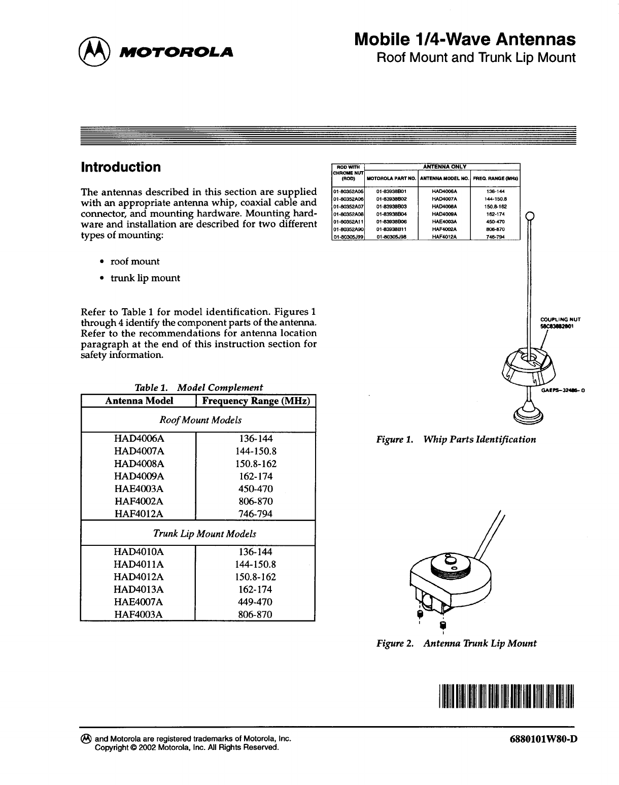
Antenna Installation Manual

June, 2002 6880101W80-C 3
Installation Mobile 1/4-Wave Antennas
Installation
Mounting Hardware Installation – Roof
Mount
General
The installation procedure which follows is for a typi-
cal passenger car. The procedure may vary slightly
with the type of vehicle on which the antenna is to be
installed. Generally speaking, however, the procedures
outlined are of a universal nature.
NOTE
The antenna should be mounted on a flat
metal roof of .020 to .040 inch thickness.
1. First, select a location for the antenna as near
the center of the roof as possible.
2. The headlining may be probed with the fin-
gers to make sure that all points of obstruction
are avoided.
Installation Procedure Single Wall Construction
1. Locate the center of the roof by careful mea-
surement, remove the headlining as necessary,
and drill a pilot hole down through the roof. If
the interior light of the car is centered in the
roof, remove this light and fixture and drill
the pilot hole up through the roof at about the
center of the interior light mountings. This
centers the antenna mount on the roof and
allows for easy access.
2. Drill a 3/4-inch hole from the top of the roof
until the saw bottoms. Use a Motorola hole
cutting saw (01-80382A25) or equivalent.
When the saw bottoms on the roof, it cleans
off the paint in a neat circle and assures good
contact with the locking nut.
IMPORTANT
For proper seating of brushing assembly,
remove burrs and scrape any foreign
matter from underside of hole out to at
least 1/8-inch from edge.
3. Determine the routing of the cable from the
antenna mounting base to the radio set; then
remove the molding and trim necessary to
facilitate pulling the cable through.
NOTE
To ensure ease of assembly, thread the
locking nut on and then off the bushing
assembly before installation. This
removes any burrs which may be
present.
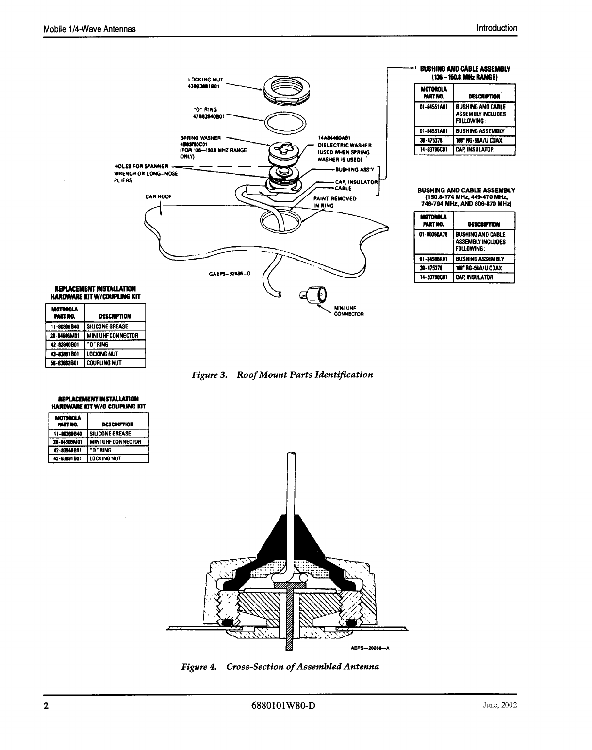
4. Refer to Figure 5. From the top, feed the
RG-58A/U lead-in cable between the headlin-
ing and the metal roof. Then route the cable
between the roof and the radio set.
5. Refer to Figure 6. The bushing assembly is
now in a position to drop into the hole in the
roof. It should be tilted at a slight angle and
fed into the 3/4-inch hold. The threaded top
will not fall through the hole.
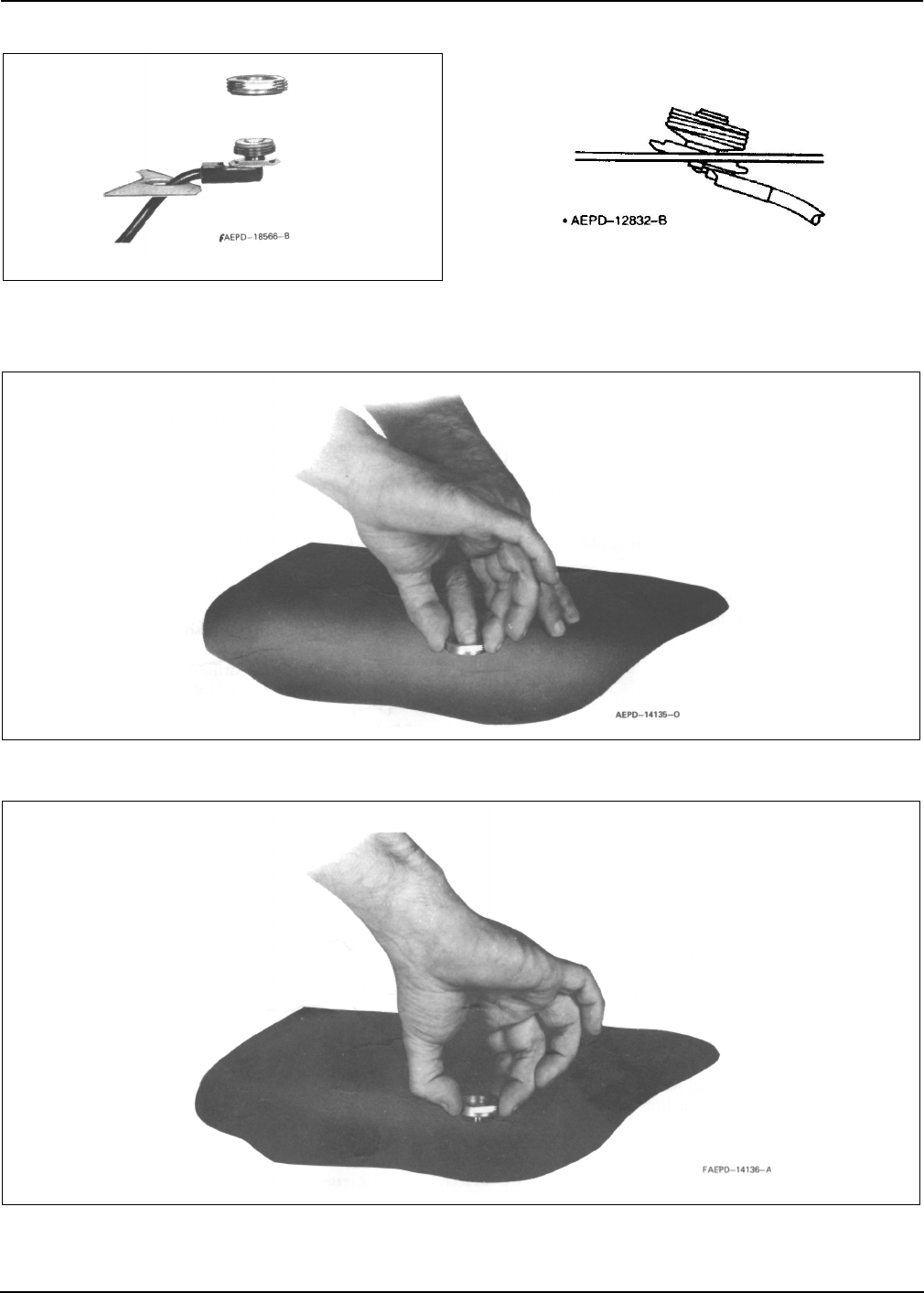
6. Refer to Figure 7. Hold the antenna bushing
assembly in place with the index finger and
thread the locking nut onto it as shown.
7. Pull up on the bushing assembly as illustrated
in Figure 8, and make sure it is centered and
seated (both shoulders inside the drilled hole),
and that the "O" ring is in the groove in the
locking nut. (As furnished, the "O" ring has
been placed in the locking nut groove and
imbedded in silicone grease.) Use a
15/16-inch open-end wrench to tighten the
locking nut until it bottoms firmly against the
roof top.
IMPORTANT
Refer to Figure 3. If the bushing assembly
should slip or rotate for any reason dur-
ing the tightening procedure, insert the
tips of a long nose plier or spanner
wrench into the two holes in the bushing
assembly and apply force to prevent
rotation until the locking nut is tight.
The locking nut must come into contact with the car
roof to insure the proper antenna radiation pattern.
This can only happen when the rubber "O" ring is fully
compressed.
8. Take up the slack in the cable and replace the
headlining retainer molding.
9. Replace headlining and dome light if
removed.
Installation Procedure - Double Wall Construction
Vehicles With Dome Lights or
Removable Headlining
1. Remove the dome light from its mount or
remove the headlining from the installation
area.
2. Drill a small pilot hole centered in the roof of
the vehicle. The center of the cavity where the
dome light was removed is sufficiently close.
3. Using a 1-1/4-inch diameter hole saw cut a
hole in the inside layer of the metal.
4 6880101W80-C June, 2002
Mobile 1/4-Wave Antennas Installation
Figure 5. Coaxial Cable Insertion Figure 6. Bushing Assembly Insertion
Figure 7. Locking Nut Positioning
Figure 8. Locking Nut Tightening
June, 2002 6880101W80-C 5
Installation Mobile 1/4-Wave Antennas
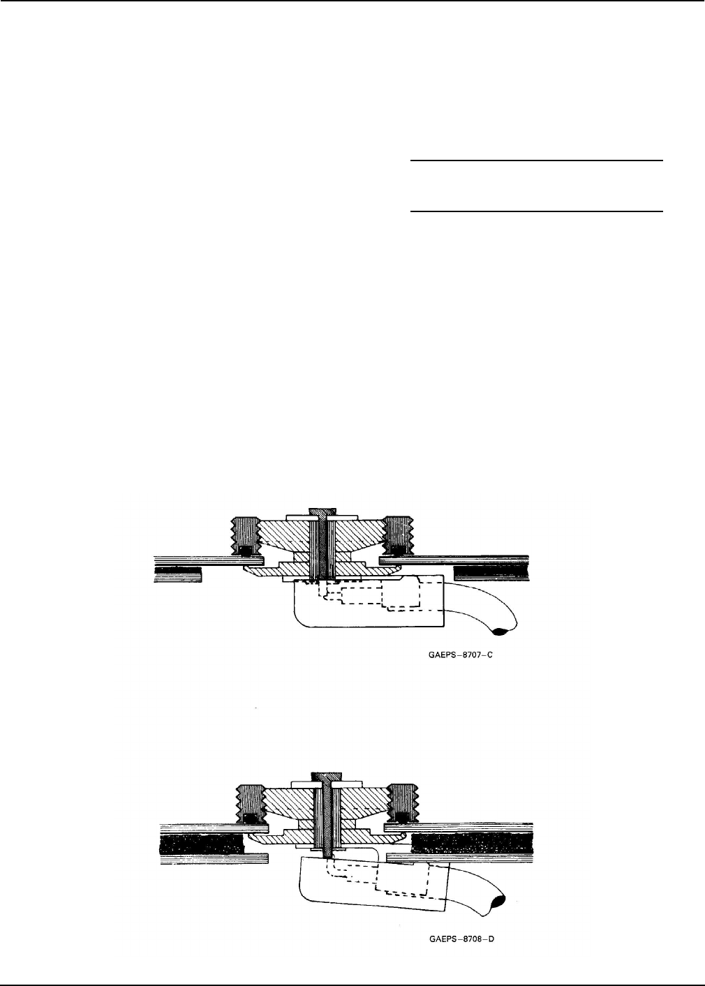
4. Remove the metal and filler from this
1-1/4-inch diameter hole.
5. Complete the installation per installation pro-
cedure given for vehicles with single wall con-
struction. A completed mount is illustrated in
Figure 9.
Vehicles Without Dome Lights
When the vehicle has no dome light, and it is not feasi-
ble to remove the headlining to get to the inside sur-
face, proceed as follows:
1. Locate the center of the roof and make sure
the area beneath this point is clear to allow
passage of a drill.
2. With a 3/4-inch diameter hole cutting saw
carefully cut a 3/4-inch hole from the top of
the roof through both thicknesses of metal.
Clean the metal in a neat circle around the
hole to assure a good contact between the roof
metal and the locking nut.
3. Remove any burrs and remove the filler sepa-
rating the roof thickness for a distance of
1/4-inch back from the hole.
4. Install the mount to the outside roof thickness
per installation procedure given for vehicles
with single wall construction.
Mounting Hardware Installation – Trunk
Lip Mount
NOTE
Not recommended for transmitters with
power outputs of 7 W or greater.
1. Refer to Figure 11 for antenna location.
2. Using the Allen wrench supplied, turn the
two set screws counterclockwise until their
threads are not visible on the underside of the
clamp bracket.
3. Raise the trunk lid to pass the coaxial cable
through; then tilt the mounting base slightly
to hook the clamp bracket on the trunk lip.
The coaxial cable, coming from under the
mounting base, may have to be bent down to
accomplish this step. When the base is in posi-
tion, the coaxial cable should not bind in any
way, or be pinched under a set screw.
4. Tighten the two set screws.
Figure 10. Roof Mount in Vehicle Without Dome Light
Figure 9. Roof Mount in Vehicle With
Dome Light or Removable Headlining
6 6880101W80-C June, 2002
Mobile 1/4-Wave Antennas Installation
NOTE
The coaxial cable will normally not be
harmed by opening and closing the
trunk, although reasonable care should
be exercised. The rubber molding around
the trunk lid will prevent damage to the
cable.
5. Route the cable from the mounting base to the
radio set. Rubber grommets should be used in
any sheet metal holes through which the cable
is routed. Ensure that the cable will not be
pinched during normal vehicle operation.
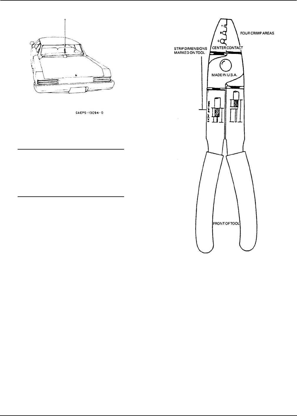
Mini-UHF Connector Installation
Use Motorola hand tool part #66-80388A26 (Refer to
Figure 12). A deluxe rachet type tool is available; order
part #66-80334B40.
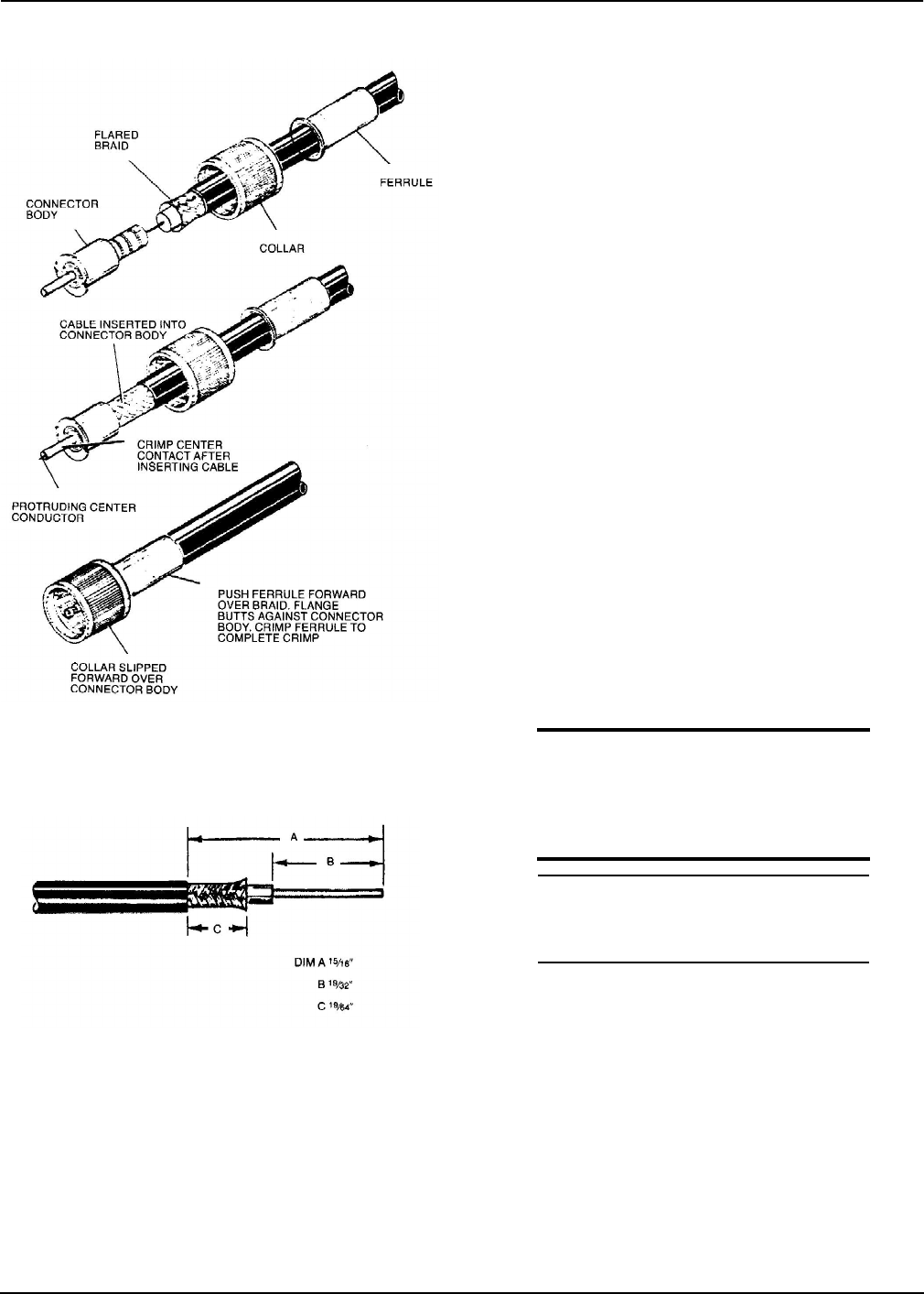
Installation Instructions
1. Slip ferrule and collar onto cable. Refer to
Figure 13.
2. Prepare cable to strip dimensions per
Figure 14, which is also marked on the hand
tool.
3. Insert stripped cable into plug body until con-
ductor is exposed (front end) and dielectric
bottoms inside body. Refer to Figure 13.
4. Crimp center contact using proper crimp
section of tool. Refer to Figure 12 marked
"CENTER CONTACT."
5. Push collar forward onto plug assembly. Fit
cable braid over the support sleeve of the con-
nector. Refer to Figure 13.
6. Push ferrule over braid until flange butts
against connector body. Refer to Figure 13.
Using the correct crimp area of the tool, crimp
the ferrule close to the plug body. See
Figure 12, crimp location "C." Crimp ferrule a
second time close to the cable end.
7. The protruding center conductor should be
trimmed flush with the end of the center con-
tact.
Figure 11. Typical Mount Location
Figure 12.
June, 2002 6880101W80-C 7
Frequency Conversion Mobile 1/4-Wave Antennas
Frequency Conversion
See Table 1. Antennas in each band are equipped with
whip radiators cut to the proper length for that specific
band. To change from one band to another, a whip
assembly of the proper length should be substituted
for one previously in use. Antennas in the 136-150.8
MHz range are also equipped with a spring washer
(roof mount models only; see Figure 3) to provide for
proper impedance matching. Should it be desired to
change from an antenna in the 136-150.8 MHz range to
one in the other ranges, this washer must be removed
in addition to changing the whip assembly. Con-
versely, to shift from the other ranges to the 136-
150.8 MHz range, a spring washer must be installed in
addition to changing the whip assembly.
Motorola Recommendations for
Mobile Antenna Location
Recommended mobile antenna installations are lim-
ited to metal body vehicles at the center of the roof and
center of the trunk deck locations. Refer to Table 2.
The antenna installation must additionally be in accor-
dance with:
•the requirements of the antenna manufac-
turer/supplier
•instructions in the Radio Installation manual.
Antenna Location
Mobile Antenna Installation
Mobile Radio Operation and EME Exposure
Observe the following caution and electromagnetic
energy exposure (EME) statements when installing
antennas:
CAUTION
Use caution when installing antennas
with mobile radio equipment using
transmitter power of 7 W or greater.
Install antennas only on metal bodied
vehicles.
NOTE
For low-power mobile radios (less than
7 W) there are no antenna type or instal-
lation restrictions.
To assure optimal radio performance and that human
exposure to radio frequency electromagnetic energy is
within the guidelines referenced in this document,
transmit only when people inside and outside the vehi-
cle are at least the minimum distance away from a
properly installed, externally-mounted antenna.
Table 3 lists the minimum distance for several different
ranges of rated radio power.
Selecting an Antenna Site
1. Install the vehicle antenna external to the
vehicle and in accordance with the require-
ments contained in this manual.
Plug Assembly Procedure
Figure 13. Plug Assembly Procedure
Figure 14.

8 6880101W80-C June, 2002
Mobile 1/4-Wave Antennas Motorola Recommendations for Mobile Antenna Location
2. The best mounting location for the antenna is
in the center of a large, flat conductive surface.
In almost all vehicles, mounting the antenna
in the center of the roof will satisfy these
requirements. A good alternative location is in
the center of the trunk lid. If you use the trunk
lid, ensure that the trunk lid is grounded by
connecting grounding straps between the
trunk lid and the vehicle chassis.
3. Ensure the antenna cable can be easily routed
to the radio. Ensure that the antenna cable is
routed separately and not in parallel to any
other vehicle wiring or mobile radio cable
wiring.
4. Check the antenna location for any electrical
interference.
NOTE
Any two metal pieces rubbing against
each other (such as seat springs, shift
levers, trunk and hood lids, exhaust
pipes, etc.) in close proximity to the
antenna can cause severe receiver inter-
ference.
5. If the vehicle is equipped with an electronic
anti-lock braking system (ABS), mount the
antenna at the center of the roof or trunk lid
and do not route the antenna cable near the
ABS Modulator Box. Mount the radio as far
away from the Modulator Box as physically
possible. This minimizes radio interference to
the modulator box from the radio.
6. Make sure the mobile radio antenna is
installed at least one foot (30.48cm) away from
any other antenna on the vehicle.
Table 2.
Standard metal passenger vehicles Center roof or center trunk lid
Vans, pickups, and other light trucks (metal roofs) Center roof
Heavy duty equipment with metal roofs (heavy duty
trucks, semi-tractors, heavy refuse trucks, cement mixer
trucks)
Center cab roof
Specialty vehicles (such as T-roofs, sun roofs, or convert-
ibles) Center trunk lid – recommended only for transmitter
output of less than 7 W.
Other vehicles Contact your Motorola Field Technical Representative.
Do not install closer than the distances shown in Table 3,
for the relevant transmitter output power, from occu-
pants or without proper antenna ground plane.
Table 3. Rated Power and Distance
Rated Power of Vehicle-installed
Mobile Two-Way Radios Minimum Distance from
Transmitting Antenna
7 to 15 W 1 Foot (30.5cm)
16 to 50 W 2 Feet (61cm)
More than 50 W 3 Feet (91.5cm)