Motorola Solutions 99FT5001 CDM1550LS+ Mobile Radio User Manual

Motorola Solutions, Inc. CDM1550LS+ Mobile Radio

Contents

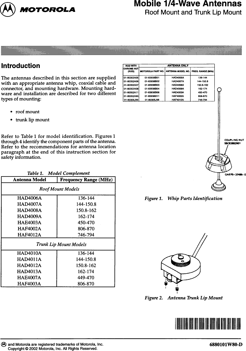
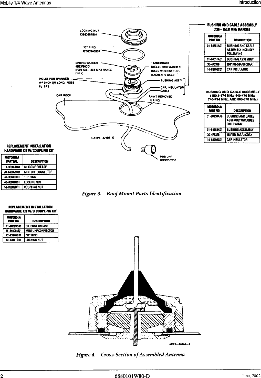
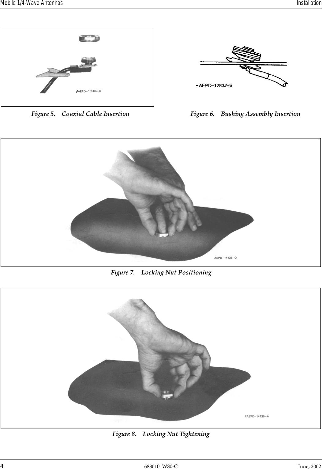
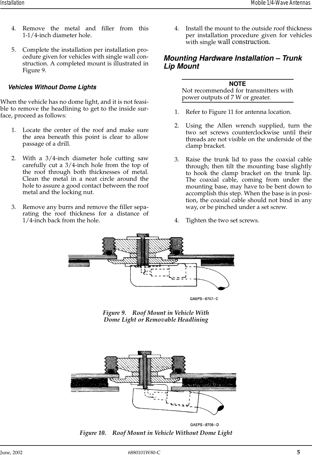
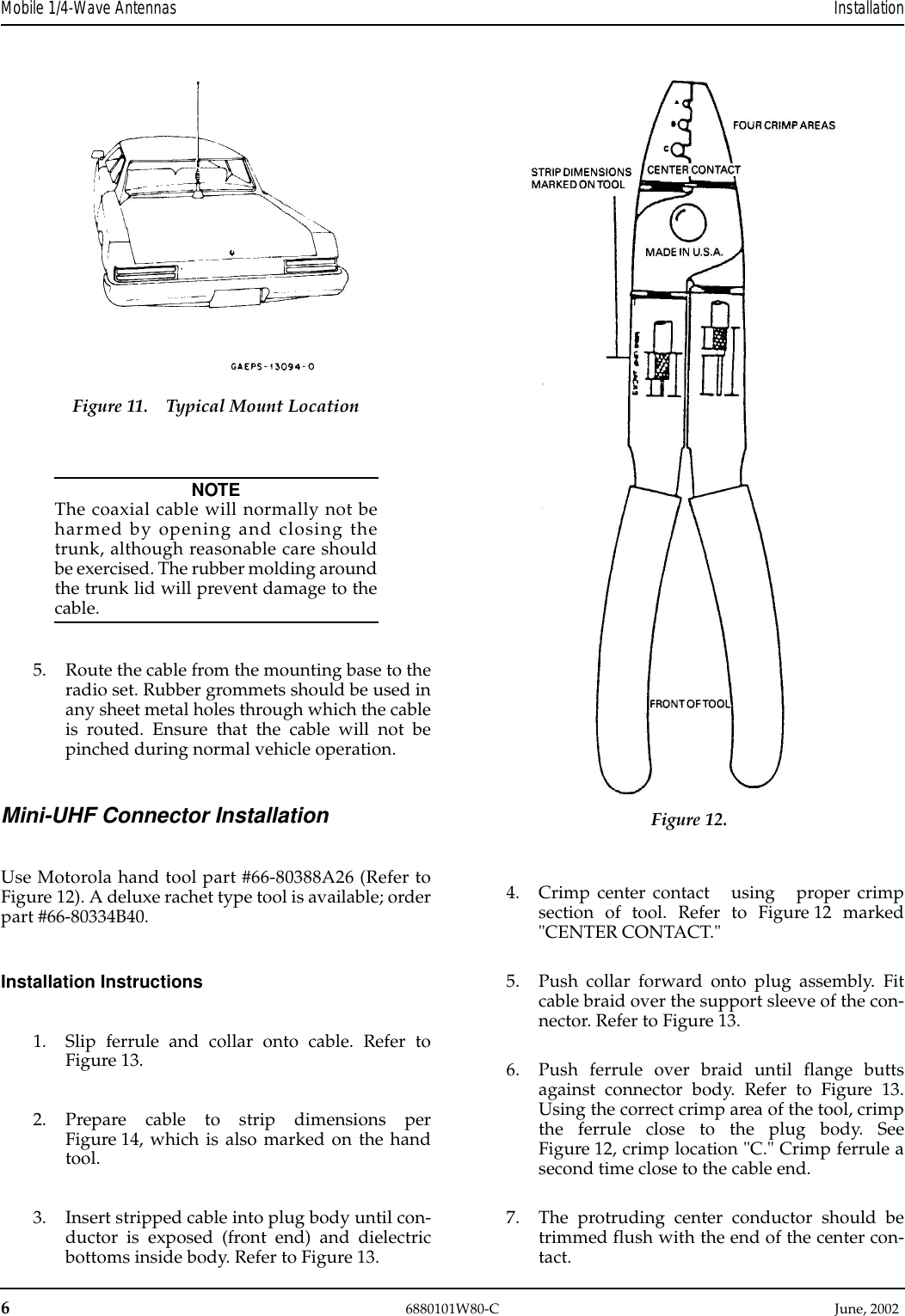
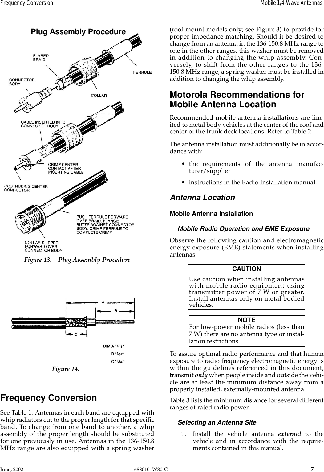
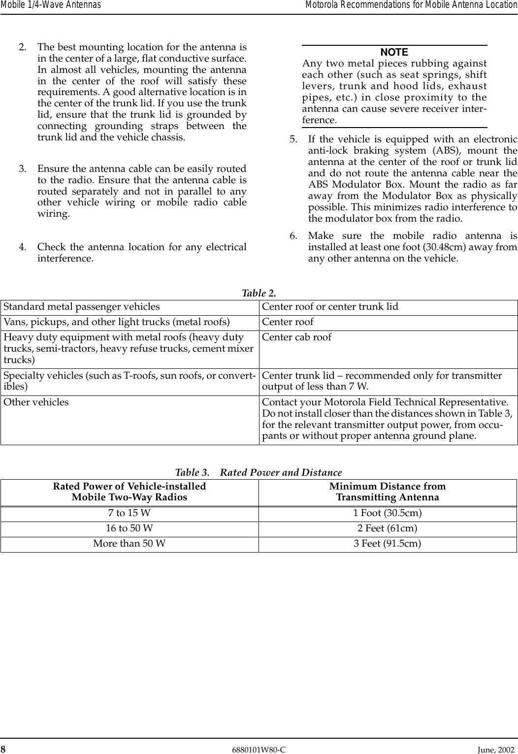
Antenna Installation Manual

June, 2002  6880101W80-C 3Installation Mobile 1/4-Wave Antennas InstallationMounting Hardware Installation – Roof MountGeneralThe installation procedure which follows is for a typi-cal passenger car. The procedure may vary slightlywith the type of vehicle on which the antenna is to beinstalled. Generally speaking, however, the proceduresoutlined are of a universal nature.NOTEThe antenna should be mounted on a flatmetal roof of .020 to .040 inch thickness.1. First, select a location for the antenna as nearthe center of the roof as possible.2. The headlining may be probed with the fin-gers to make sure that all points of obstructionare avoided.Installation Procedure Single Wall Construction1. Locate the center of the roof by careful mea-surement, remove the headlining as necessary,and drill a pilot hole down through the roof. Ifthe interior light of the car is centered in theroof, remove this light and fixture and drillthe pilot hole up through the roof at about thecenter of the interior light mountings. Thiscenters the antenna mount on the roof andallows for easy access.2. Drill a 3/4-inch hole from the top of the roofuntil the saw bottoms. Use a Motorola holecutting saw (01-80382A25) or equivalent.When the saw bottoms on the roof, it cleansoff the paint in a neat circle and assures goodcontact with the locking nut.IMPORTANTFor proper seating of brushing assembly,remove burrs and scrape any foreignmatter from underside of hole out to atleast 1/8-inch from edge.3. Determine the routing of the cable from theantenna mounting base to the radio set; thenremove the molding and trim necessary tofacilitate pulling the cable through.NOTETo ensure ease of assembly, thread thelocking nut on and then off the bushingassembly before installation. Thisremoves any burrs which may bepresent.4. Refer to Figure 5. From the top, feed theRG-58A/U lead-in cable between the headlin-ing and the metal roof. Then route the cablebetween the roof and the radio set.5. Refer to Figure 6. The bushing assembly isnow in a position to drop into the hole in theroof. It should be tilted at a slight angle andfed into the 3/4-inch hold. The threaded topwill not fall through the hole.6. Refer to Figure 7. Hold the antenna bushingassembly in place with the index finger andthread the locking nut onto it as shown.7. Pull up on the bushing assembly as illustratedin Figure 8, and make sure it is centered andseated (both shoulders inside the drilled hole),and that the "O" ring is in the groove in thelocking nut. (As furnished, the "O" ring hasbeen placed in the locking nut groove andimbedded in silicone grease.) Use a15/16-inch open-end wrench to tighten thelocking nut until it bottoms firmly against theroof top.IMPORTANTRefer to Figure 3. If the bushing assemblyshould slip or rotate for any reason dur-ing the tightening procedure, insert thetips of a long nose plier or spannerwrench into the two holes in the bushingassembly and apply force to preventrotation until the locking nut is tight.The locking nut must come into contact with the carroof to insure the proper antenna radiation pattern.This can only happen when the rubber "O" ring is fullycompressed. 8. Take up the slack in the cable and replace theheadlining retainer molding. 9. Replace headlining and dome light ifremoved.Installation Procedure - Double Wall ConstructionVehicles With Dome Lights orRemovable Headlining1. Remove the dome light from its mount orremove the headlining from the installationarea.2. Drill a small pilot hole centered in the roof ofthe vehicle. The center of the cavity where thedome light was removed is sufficiently close.3. Using a 1-1/4-inch diameter hole saw cut ahole in the inside layer of the metal.
4 6880101W80-C           June, 2002Mobile 1/4-Wave Antennas InstallationFigure 5. Coaxial Cable Insertion Figure 6. Bushing Assembly InsertionFigure 7. Locking Nut PositioningFigure 8. Locking Nut Tightening
June, 2002  6880101W80-C 5Installation Mobile 1/4-Wave Antennas 4. Remove the metal and filler from this1-1/4-inch diameter hole.5. Complete the installation per installation pro-cedure given for vehicles with single wall con-struction. A completed mount is illustrated inFigure 9.Vehicles Without Dome LightsWhen the vehicle has no dome light, and it is not feasi-ble to remove the headlining to get to the inside sur-face, proceed as follows:1. Locate the center of the roof and make surethe area beneath this point is clear to allowpassage of a drill. 2. With a 3/4-inch diameter hole cutting sawcarefully cut a 3/4-inch hole from the top ofthe roof through both thicknesses of metal.Clean the metal in a neat circle around thehole to assure a good contact between the roofmetal and the locking nut.3. Remove any burrs and remove the filler sepa-rating the roof thickness for a distance of1/4-inch back from the hole.4. Install the mount to the outside roof thicknessper installation procedure given for vehicleswith single wall construction.Mounting Hardware Installation – Trunk Lip MountNOTENot recommended for transmitters withpower outputs of 7 W or greater.1. Refer to Figure 11 for antenna location.2. Using the Allen wrench supplied, turn thetwo set screws counterclockwise until theirthreads are not visible on the underside of theclamp bracket.3. Raise the trunk lid to pass the coaxial cablethrough; then tilt the mounting base slightlyto hook the clamp bracket on the trunk lip.The coaxial cable, coming from under themounting base, may have to be bent down toaccomplish this step. When the base is in posi-tion, the coaxial cable should not bind in anyway, or be pinched under a set screw.4. Tighten the two set screws.Figure 10. Roof Mount in Vehicle Without Dome LightFigure 9. Roof Mount in Vehicle WithDome Light or Removable Headlining
6 6880101W80-C          June, 2002Mobile 1/4-Wave Antennas InstallationNOTEThe coaxial cable will normally not beharmed by opening and closing thetrunk, although reasonable care shouldbe exercised. The rubber molding aroundthe trunk lid will prevent damage to thecable.5. Route the cable from the mounting base to theradio set. Rubber grommets should be used inany sheet metal holes through which the cableis routed. Ensure that the cable will not bepinched during normal vehicle operation.Mini-UHF Connector InstallationUse Motorola hand tool part #66-80388A26 (Refer toFigure 12). A deluxe rachet type tool is available; orderpart #66-80334B40.Installation Instructions1. Slip ferrule and collar onto cable. Refer toFigure 13.2. Prepare cable to strip dimensions perFigure 14, which is also marked on the handtool.3. Insert stripped cable into plug body until con-ductor is exposed (front end) and dielectricbottoms inside body. Refer to Figure 13.4. Crimp center contact   using   proper crimpsection of tool. Refer to Figure 12 marked"CENTER CONTACT."5. Push collar forward onto plug assembly. Fitcable braid over the support sleeve of the con-nector. Refer to Figure 13.6. Push ferrule over braid until flange buttsagainst connector body. Refer to Figure 13.Using the correct crimp area of the tool, crimpthe ferrule close to the plug body. SeeFigure 12, crimp location "C." Crimp ferrule asecond time close to the cable end.7. The protruding center conductor should betrimmed flush with the end of the center con-tact.Figure 11. Typical Mount LocationFigure 12.
June, 2002   6880101W80-C  7Frequency Conversion Mobile 1/4-Wave Antennas Frequency ConversionSee Table 1. Antennas in each band are equipped withwhip radiators cut to the proper length for that specificband. To change from one band to another, a whipassembly of the proper length should be substitutedfor one previously in use. Antennas in the 136-150.8MHz range are also equipped with a spring washer(roof mount models only; see Figure 3) to provide forproper impedance matching. Should it be desired tochange from an antenna in the 136-150.8 MHz range toone in the other ranges, this washer must be removedin addition to changing the whip assembly. Con-versely, to shift from the other ranges to the 136-150.8 MHz range, a spring washer must be installed inaddition to changing the whip assembly.Motorola Recommendations for Mobile Antenna LocationRecommended mobile antenna installations are lim-ited to metal body vehicles at the center of the roof andcenter of the trunk deck locations. Refer to Table 2.The antenna installation must additionally be in accor-dance with:•the requirements of the antenna manufac-turer/supplier•instructions in the Radio Installation manual.Antenna LocationMobile Antenna InstallationMobile Radio Operation and EME ExposureObserve the following caution and electromagneticenergy exposure (EME) statements when installingantennas:CAUTIONUse caution when installing antennaswith mobile radio equipment usingtransmitter power of 7 W or greater.Install antennas only on metal bodiedvehicles.NOTEFor low-power mobile radios (less than7 W) there are no antenna type or instal-lation restrictions.To assure optimal radio performance and that humanexposure to radio frequency electromagnetic energy iswithin the guidelines referenced in this document,transmit only when people inside and outside the vehi-cle are at least the minimum distance away from aproperly installed, externally-mounted antenna.Table 3 lists the minimum distance for several differentranges of rated radio power.Selecting an Antenna Site1. Install the vehicle antenna external  to thevehicle and in accordance with the require-ments contained in this manual.Plug Assembly ProcedureFigure 13. Plug Assembly ProcedureFigure 14.
8 6880101W80-C          June, 2002Mobile 1/4-Wave Antennas Motorola Recommendations for Mobile Antenna Location2. The best mounting location for the antenna isin the center of a large, flat conductive surface.In almost all vehicles, mounting the antennain the center of the roof will satisfy theserequirements. A good alternative location is inthe center of the trunk lid. If you use the trunklid, ensure that the trunk lid is grounded byconnecting grounding straps between thetrunk lid and the vehicle chassis.3. Ensure the antenna cable can be easily routedto the radio. Ensure that the antenna cable isrouted separately and not in parallel to anyother vehicle wiring or mobile radio cablewiring.4. Check the antenna location for any electricalinterference.NOTEAny two metal pieces rubbing againsteach other (such as seat springs, shiftlevers, trunk and hood lids, exhaustpipes, etc.) in close proximity to theantenna can cause severe receiver inter-ference.5. If the vehicle is equipped with an electronicanti-lock braking system (ABS), mount theantenna at the center of the roof or trunk lidand do not route the antenna cable near theABS Modulator Box. Mount the radio as faraway from the Modulator Box as physicallypossible. This minimizes radio interference tothe modulator box from the radio.6. Make sure the mobile radio antenna isinstalled at least one foot (30.48cm) away fromany other antenna on the vehicle.Table 2.Standard metal passenger vehicles Center roof or center trunk lidVans, pickups, and other light trucks (metal roofs) Center roofHeavy duty equipment with metal roofs (heavy duty trucks, semi-tractors, heavy refuse trucks, cement mixer trucks)Center cab roofSpecialty vehicles (such as T-roofs, sun roofs, or convert-ibles) Center trunk lid – recommended only for transmitter output of less than 7 W.Other vehicles Contact your Motorola Field Technical Representative. Do not install closer than the distances shown in Table 3, for the relevant transmitter output power, from occu-pants or without proper antenna ground plane.Table 3. Rated Power and DistanceRated Power of Vehicle-installedMobile Two-Way Radios Minimum Distance fromTransmitting Antenna7 to 15 W 1 Foot (30.5cm)16 to 50 W 2 Feet (61cm)More than 50 W 3 Feet (91.5cm)

Navigation menu