Moxa W5X08 Wireless gateway User Manual
Moxa Inc. Wireless gateway Users Manual
UserManual.wiki
>
Moxa
>
W5X08 User Manual
Users Manual
Navigation menu
Upload a User Manual
Namespaces
Wiki Guide
HTML
PDF
Info
Views
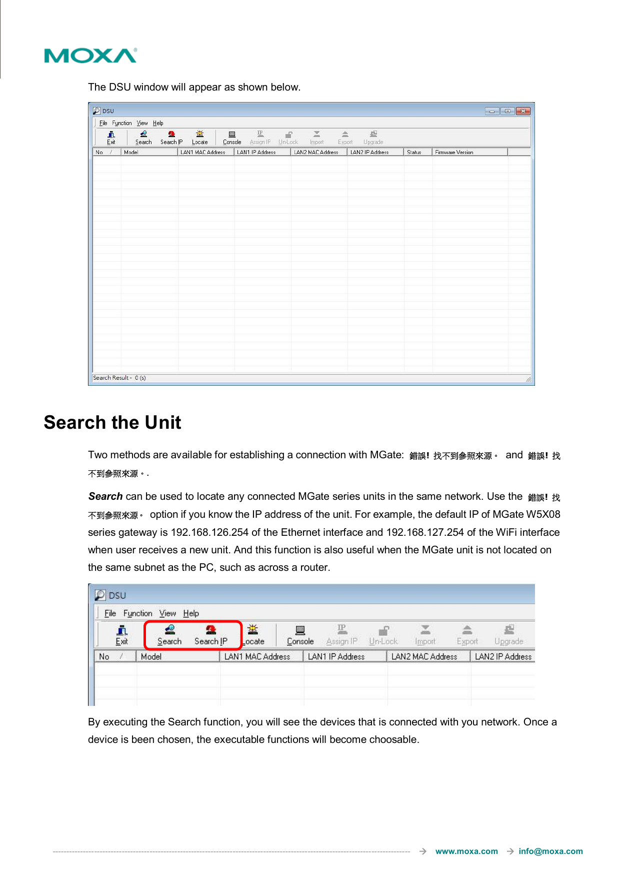
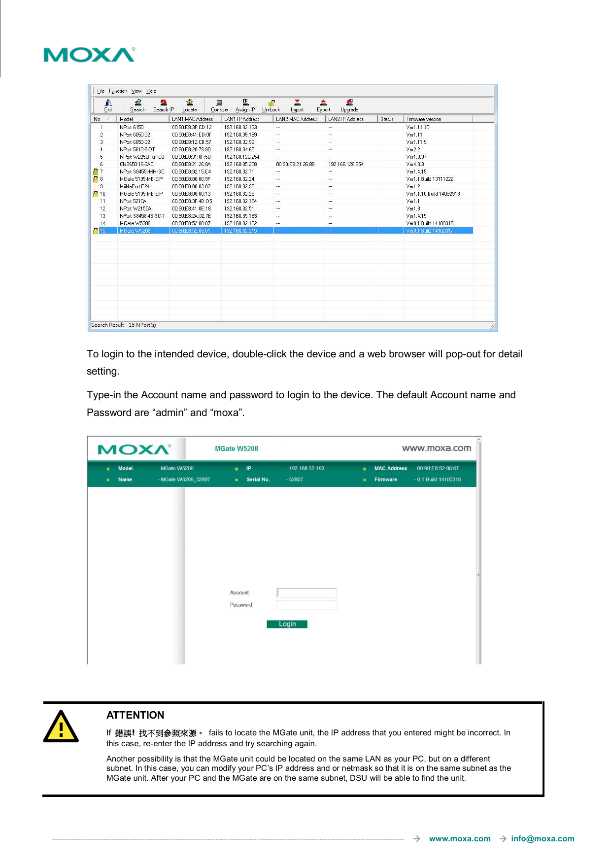
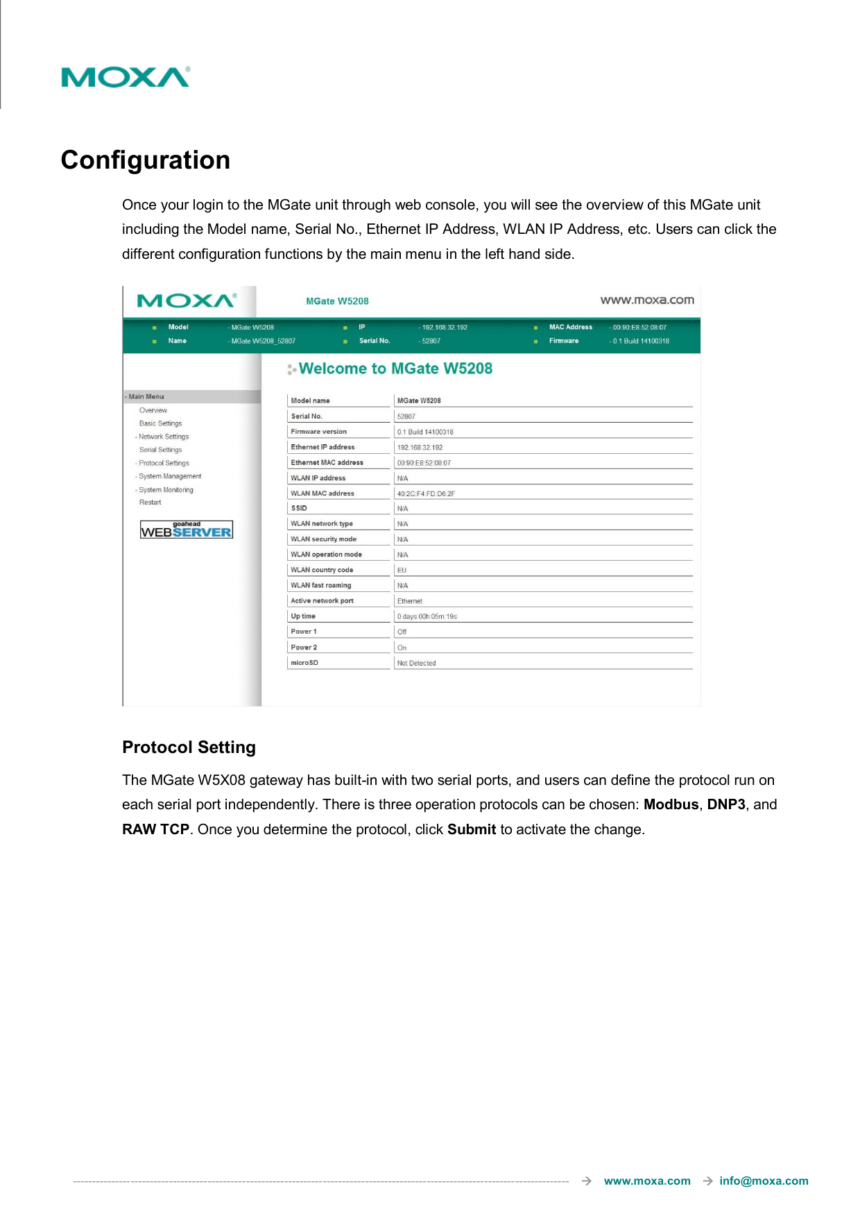
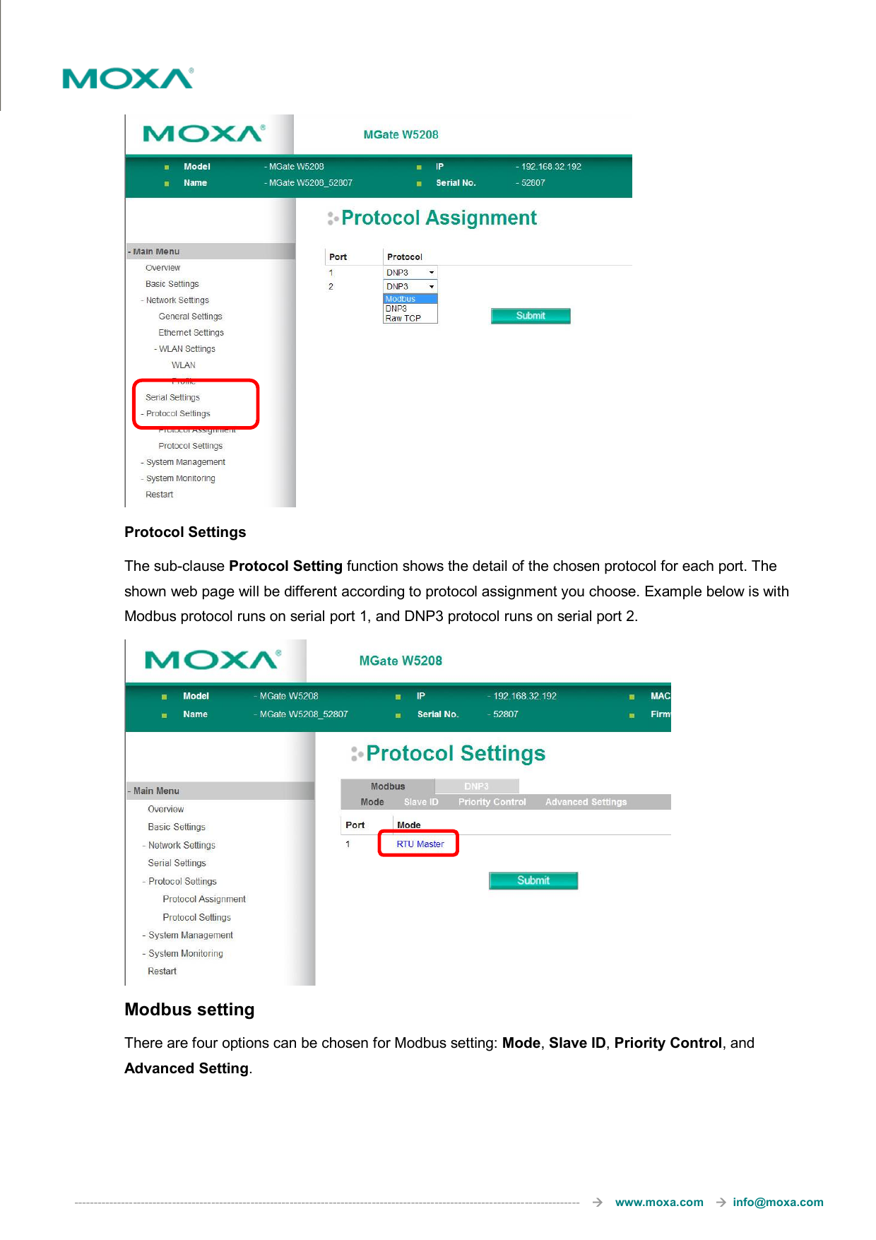
User Manual
Discussion / Help
Navigation