Users Manual

--------------------------------------------------------------------------------------------------------------------------------- www.moxa.com info@moxa.com
The Quick Install Guide for
MGate W5x08 Gateway

--------------------------------------------------------------------------------------------------------------------------------- www.moxa.com info@moxa.com
Connecting the Power
The MGate W5X08 series gateway can be powered by connecting a power source to the terminal block,
as follows:
1. Loosen or remove the screws on the terminal block.
2. Turn off the power source and then connect a 12–48 VDC power line to the terminal block.
3. Tighten the connections using the screws on the terminal block.
4. Turn on the power source.
Note that the unit does not have an on/off switch. It automatically turns on when it receives power. The
PWR LED on the top panel will glow to indicate that the unit is receiving power.
Connecting Modbus/DNP3 Serial Devices
The unit’s Modbus/DNP3 port(s) are located on the front panel. Use a Modbus/DNP3 serial cable to
connect the unit directly to the Modbus/DNP3 devices. Before connecting or removing the
Modbus/DNP3 connection, first make sure the power source is off.
Connecting Modbus/DNP3 Network Devices
The MGate W5X08 can be connected to the network via Ethernet port and WiFi with different IP
addresses. The default IP addresses of Ethernet and WiFi are 192.168.126.254 and 192.168.127.254,
respectively. Since your system may be using more than one MGate device and all MGate devices are
configured with the same factory default IP address, you will first need to configure the MGate’s
network settings. The MGate’s Ethernet ports are located on the front panel. The MGate will indicate a
valid connection to the Ethernet in the following ways:
• The Ethernet LED will glow a solid green color when connected to a 100 Mbps Ethernet network.
• The Ethernet LED will glow a solid amber color when connected to a 10 Mbps Ethernet network.
The Ethernet LED will flash when Ethernet packets are being transmitted or received.
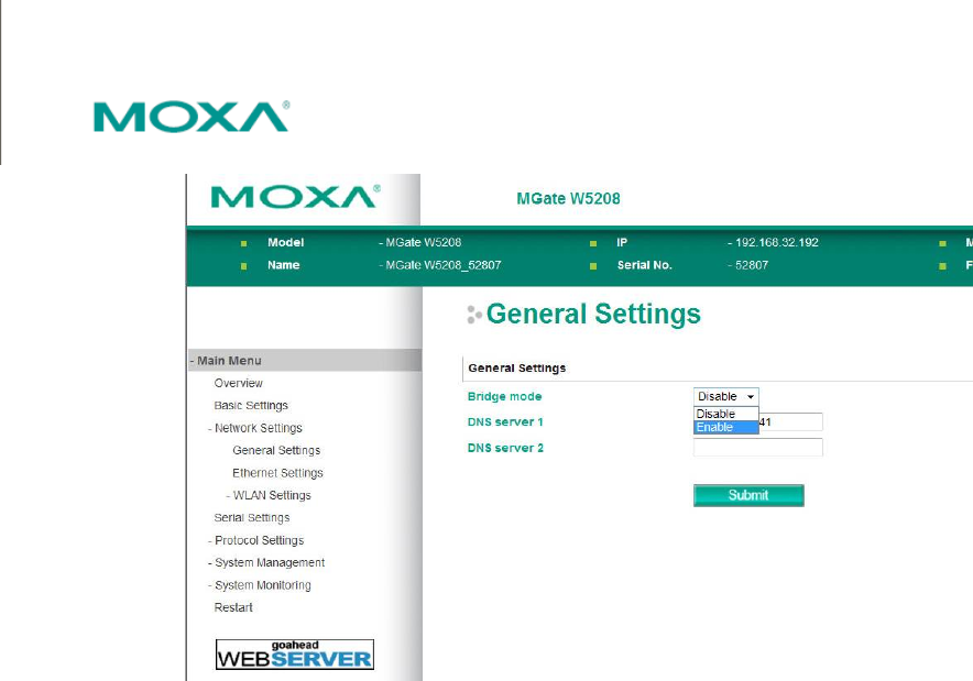
In General Settings, users can choose the routing criteria by Bridge mode setting when Ethernet and
WiFi are both connected. When disable the bridge mode, Ethernet port will be the default routing path
even WiFi is also connected. When enable the bridge mode, WiFi connection will be the default routing
path even Ethernet port is connected.
--------------------------------------------------------------------------------------------------------------------------------- www.moxa.com info@moxa.com
WLAN Settings
The MGate W5X08 supports IEEE 802.11 a/b/g/n wireless function. The wireless function provides
more convenient deployment of industrial equipments connecting to network. It has better scalability to
meet the requirement of a variety of topologies according to user’s needs of wireless LAN system.
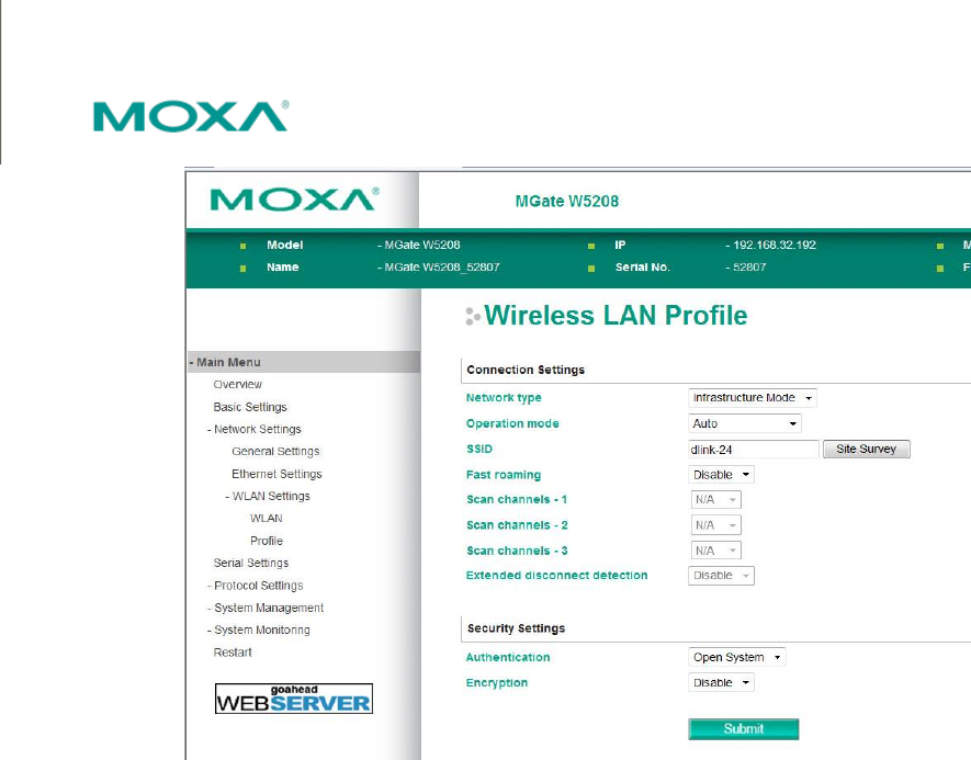
Connection Settings
The WLAN settings are classified into two types. The first one is “WLAN” setting which includes IP
address/Network/Gateway and the method of acquiring IP address. The setting is for user to specify
network address to run in the system. The second one is “Profile” which is used to configure the
wireless connection settings including security parameters.
There are two network types which is “Infrastructure” and “Adhoc mode.” When configured to “Adhoc
mode”, it automatically detects and communicates directly with each other and do not require a
wireless access point (AP) or gateway. If the MGate is configured to “Infrastructure”, it is accessed
through a wireless access point. In the “Operation mode”, you can choose the MGate to operate in
which wireless standard. The SSID is used to configure the SSID of access point. You can also get the
SSID by “Site survey” button which will automatically search and list the SSID of APs nearby. The fast
roaming is used for roaming among two APs with the same SSID when the wireless signal strength is
stronger than the original attached one. The “Scan channel” is configured for fast roaming function to
do the scanning of wireless signal. It is selectable only if “Fast roaming” is enabled. The list of
selectable channels is different according to different operation mode.
Security Settings
For the security setting of “Infrastructure” mode, it must be the same as access point for authorization
of communication. The authentication field specifies how wireless devices will be authenticated. Only
authenticated devices will be allowed to communicate with the access point. The security setting of the
wireless devices which are configured to “Adhoc mode” must be the same to communicate with each
other.
--------------------------------------------------------------------------------------------------------------------------------- www.moxa.com info@moxa.com
First Time Use
Firstly, user can connect with the MGate device and search the unit by using the Device Search Utility.
And then configure the MGate through web console.
1. Device Search Utility (called DSU in this instruction)
In most situations, users do not know the IP address when setting up a new gateway or configuring
an existing gateway. In these cases, users can use an Ethernet cable to connect a host computer
and the gateway directly. If connecting the devices under the same Ethernet switch, make sure
there is no router between them. The DSU can detect the network settings of the connected
gateway for users properly. Once you found the device in the DSU’s device list, you can assign IP to
the device, or export/import the configuration file, or upgrade the firmware to the device. For other
gateway configuration, double-click the target device in the DSU and the web browser will pop-up
for further setting.
2. Web Console
Use the Web Console to configure the MGate or to verify the status of the MGate from a web
browser. You may use Microsoft Internet Explorer or Google Chrome to connect to the MGate. To
use this method, the IP address of the MGate must be configured correctly.
Starting Device Search Utility
The Device Search Utility (called DSU in this instruction) is a Windows-based utility that is used to
configure MGate W5X08 series gateway units. Before running DSU, first connect your MGate W5X08
series gateway unit to your PC.
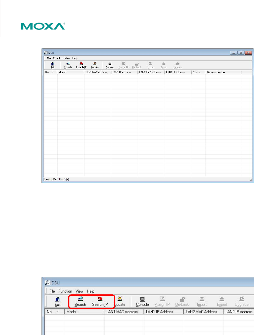
To start DSU, from the Windows Start menu click Start Programs MOXA DSU DSU.
--------------------------------------------------------------------------------------------------------------------------------- www.moxa.com info@moxa.com
The DSU window will appear as shown below.
Search the Unit
Two methods are available for establishing a connection with MGate: 錯誤! 找不到參照來源。 and 錯誤! 找
不到參照來源。.
Search can be used to locate any connected MGate series units in the same network. Use the 錯誤! 找
不到參照來源。 option if you know the IP address of the unit. For example, the default IP of MGate W5X08
series gateway is 192.168.126.254 of the Ethernet interface and 192.168.127.254 of the WiFi interface
when user receives a new unit. And this function is also useful when the MGate unit is not located on
the same subnet as the PC, such as across a router.
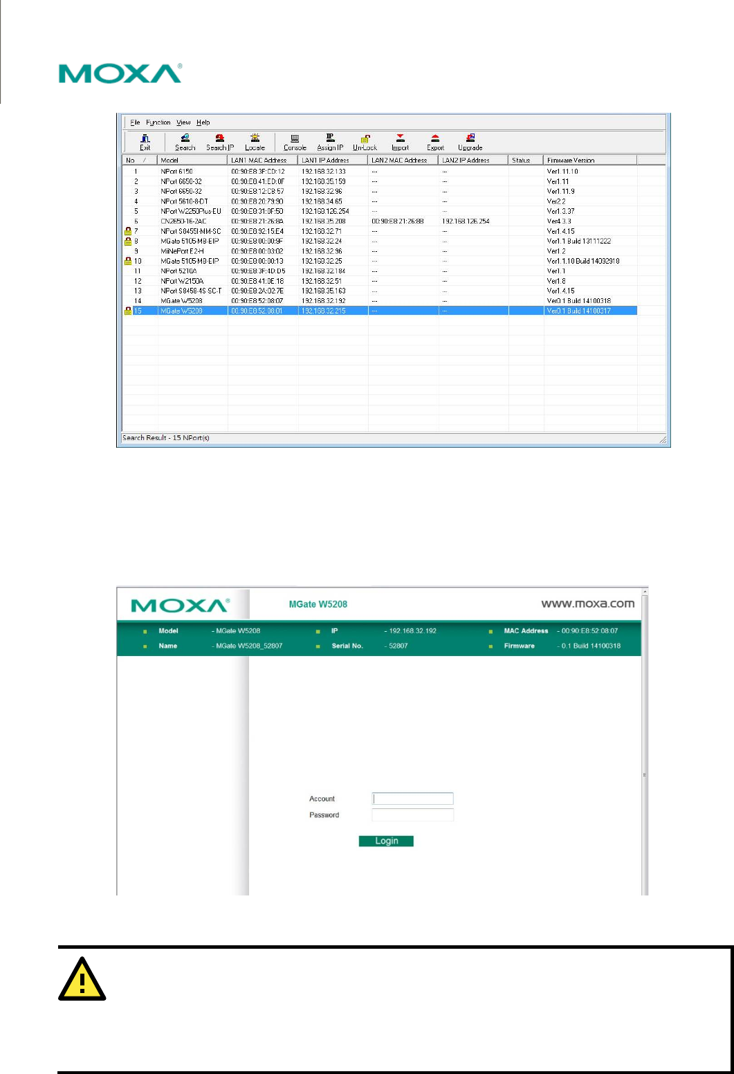
By executing the Search function, you will see the devices that is connected with you network. Once a
device is been chosen, the executable functions will become choosable.
--------------------------------------------------------------------------------------------------------------------------------- www.moxa.com info@moxa.com
To login to the intended device, double-click the device and a web browser will pop-out for detail
setting.
Type-in the Account name and password to login to the device. The default Account name and
Password are “admin” and “moxa”.
ATTENTION
If 錯誤! 找不到參照來源。 fails to locate the MGate unit, the IP address that you entered might be incorrect. In
this case, re-enter the IP address and try searching again.
Another possibility is that the MGate unit could be located on the same LAN as your PC, but on a different
subnet. In this case, you can modify your PC’s IP address and or netmask so that it is on the same subnet as the
MGate unit. After your PC and the MGate are on the same subnet, DSU will be able to find the unit.
--------------------------------------------------------------------------------------------------------------------------------- www.moxa.com info@moxa.com
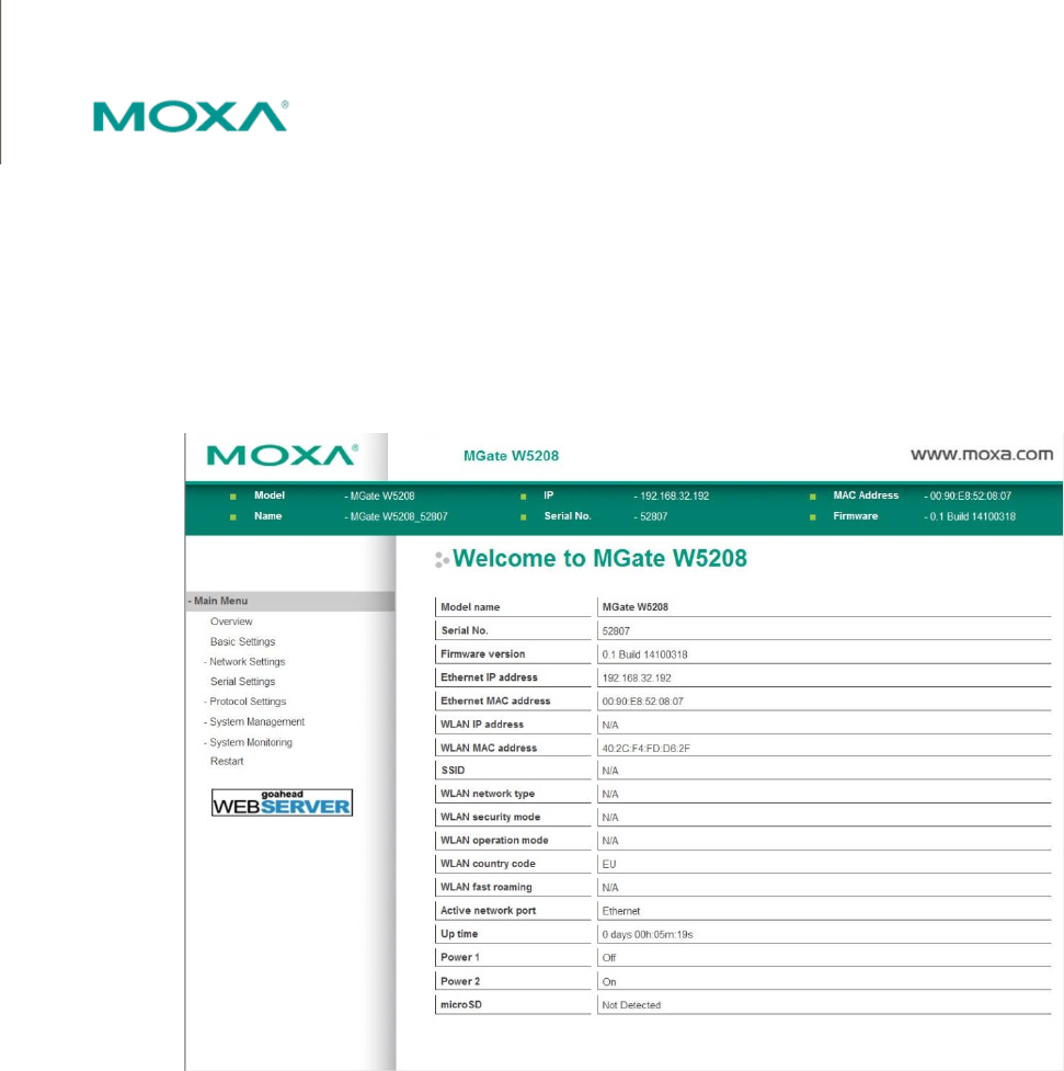
Configuration
Once your login to the MGate unit through web console, you will see the overview of this MGate unit
including the Model name, Serial No., Ethernet IP Address, WLAN IP Address, etc. Users can click the
different configuration functions by the main menu in the left hand side.
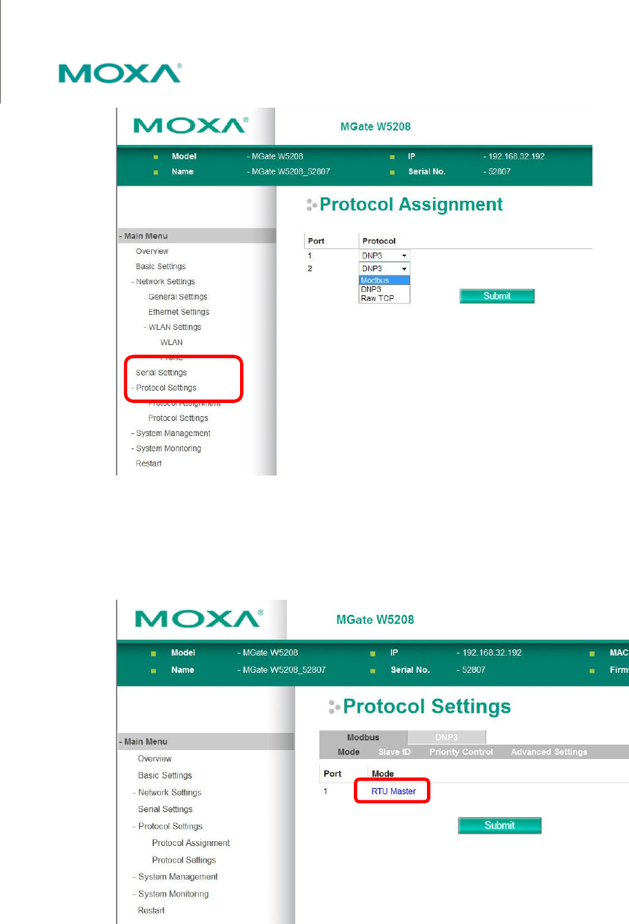
Protocol Setting
The MGate W5X08 gateway has built-in with two serial ports, and users can define the protocol run on
each serial port independently. There is three operation protocols can be chosen: Modbus, DNP3, and
RAW TCP. Once you determine the protocol, click Submit to activate the change.
--------------------------------------------------------------------------------------------------------------------------------- www.moxa.com info@moxa.com
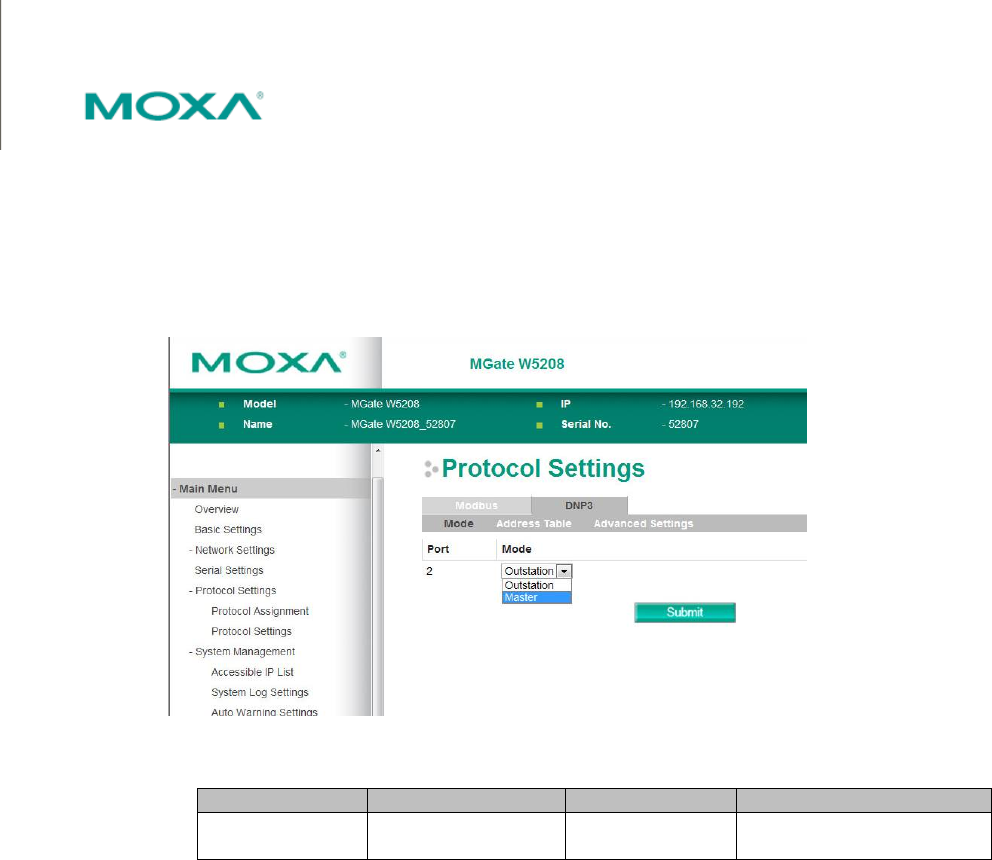
Protocol Settings
The sub-clause Protocol Setting function shows the detail of the chosen protocol for each port. The
shown web page will be different according to protocol assignment you choose. Example below is with
Modbus protocol runs on serial port 1, and DNP3 protocol runs on serial port 2.
Modbus setting
There are four options can be chosen for Modbus setting: Mode, Slave ID, Priority Control, and
Advanced Setting.
--------------------------------------------------------------------------------------------------------------------------------- www.moxa.com info@moxa.com
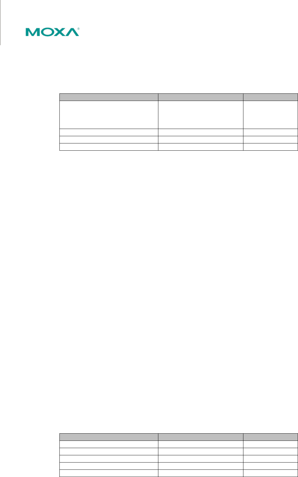
Mode
Click the currently shown Modbus mode (RTU Master shown in previous figure) for each port for further
setting. It includes the mode of the Connected serial device, Response timeout, Inter-character
timeout, and Inter-frame delay.
Parameter Value Default
Connected serial device
RTU Slave,
RTU Master,
ASCII Slave,
ASCII Master
RTU Slave
Response timeout 10 – 120000 ms 1000 ms
Inter-character timeout 10 – 500 ms, 0 for auto 0
Inter-frame delay 10 – 500 ms, 0 for auto 0
Connected serial device
This field is to assign the role of the connected serial device, please refer to the manual of the serial
devices for the setting.
Response timeout
This field is used to configure how long the gateway will wait for a response from a Modbus ASCII or
RTU slave. This field is set independently for each serial port, which is selected through the “Protocol
Assignment” field. Please refer to your device manufacturer’s documentation to manually set the
response time-out.
The MGate W5X08 series gateway also provides automatic calibration of the response timeout. Instead
of manually figuring out the appropriate setting, you can click “Auto Detection” to have the MGate
automatically figure out the time-out setting. Once a value has been recommended, you can fine-tune it
for best performance.
Inter-Character Timeout
Use this function to determine the timeout interval between characters for Modbus devices that cannot
receive Rx signals within an expected time interval. If the response is timed out, all received data will be
discarded. Note that this timeout mechanism only works in RTU slave mode. The MGate W5X08
gateway will automatically determine the timeout interval if the timeout value is set to 0.
Inter-Frame Delay
In Modbus RTU slave mode, user can determine the time-delay to transmit the data frame received
from the slave device to the upstream. The MGate W5X08 gateway will automatically determine the
time interval if it is set to 0.
Slave ID
The Slave ID Map tab is where slave IDs are managed. The definitions on this tab determine how
requests will be routed by the unit.
Parameter Value Default
Remote IP address (Max 40 characters) null
TCP Port 0 - 65535 null
Slave ID Start 0 – 255 0
Slave ID End 0 - 255 0
Slave ID Offset -255 ~ 255 0

--------------------------------------------------------------------------------------------------------------------------------- www.moxa.com info@moxa.com
How Slave IDs are Mapped on the MGate W5X08
When a Modbus master requests information from a Modbus slave, the request is addressed to the
desired slave's ID, which must be unique on the network. When Modbus networks are integrated by a
Modbus gateway, complications can arise if the same slave ID is being used on different networks. If this
is not properly addressed, a request sent to that slave ID would receive more than one response,
causing communication problems.
With the MGate MB3000, this situation is addressed by using a slave ID map. While configuring the
MGate, users set up a range of "virtual" slave IDs that are mapped to slave devices on a specific
Modbus network. To send a request to a slave that is on a different Modbus network, a master would
address the request to the appropriate virtual slave ID. The MGate then routes that request as specified
by the slave ID map.
For example, if a TCP master needs information from an ASCII slave, it addresses the request to the
corresponding virtual slave ID as defined on the MGate's slave ID map. The MGate identifies the request
as within its virtual slave ID range and forwards the request to the Modbus ASCII network, this time
addressed to the device's actual slave ID.
Virtual slave IDs must not conflict with each other or with other TCP slave IDs.
With the slave ID map, smart routing is achieved for units with multiple serial ports. Since each virtual
slave ID is routed to a specific Modbus network, requests are not broadcast over all serial ports. This
keeps communication efficient and prevents devices on one port from slowing down the whole system.
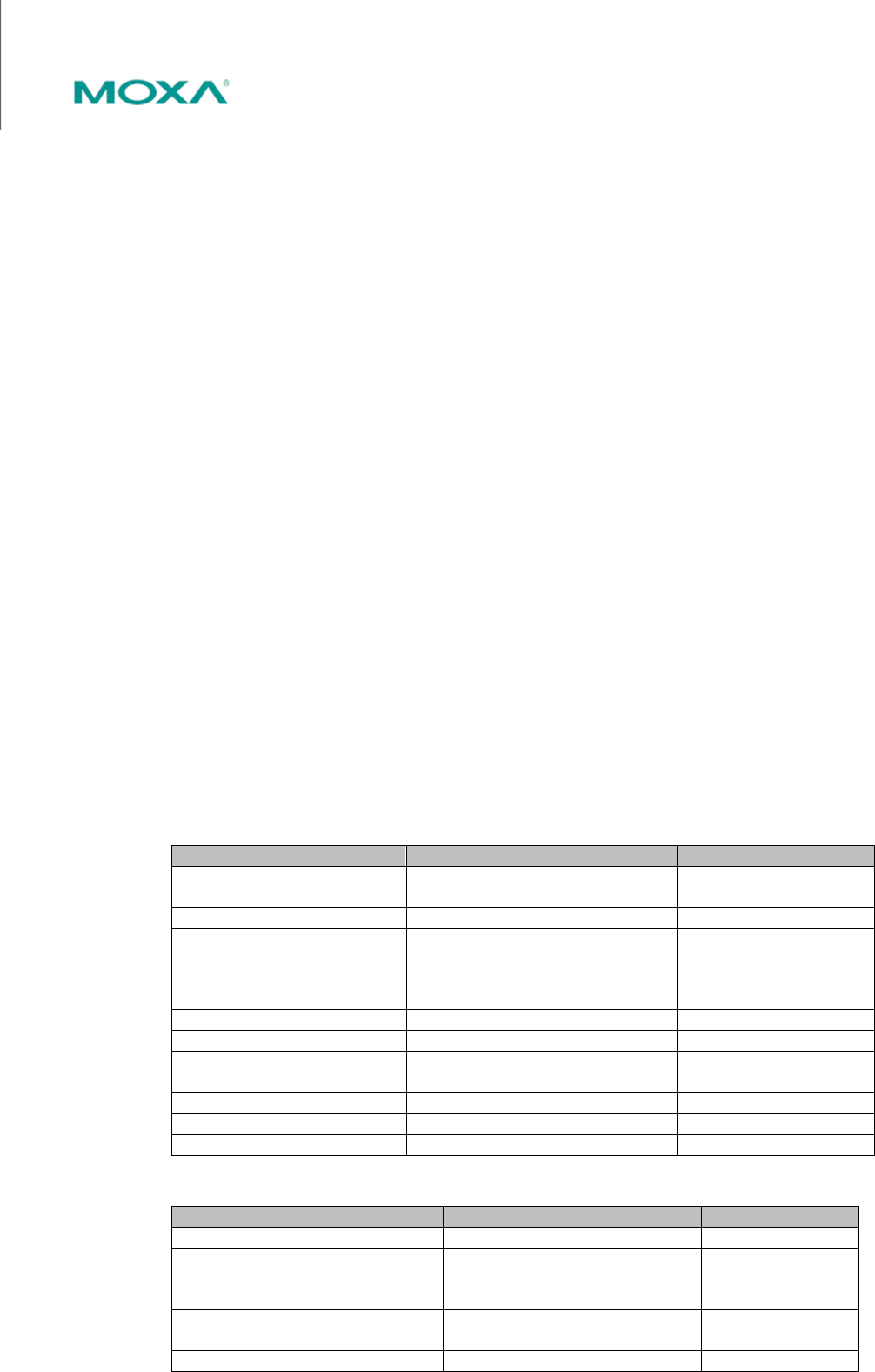
How Slave ID Map is Defined
The slave ID map consists of entries (channels) that specify a range of virtual IDs, the destination, and
the offset value. The offset value is used to convert the virtual ID to the actual ID.
Setting Value Notes
Virtual Slaves ID
Range
(numeric range
from
1 to 254)
This specifies the range of IDs that
will be routed to the selected set of
slave devices. For example, you can
specify that IDs between 8 and 24 be
routed to the devices on Port 3. The
ID 255 is reserved for the gateway
itself
Slave ID Offset (number between
-253 and 253)
This specifies the difference
between the virtual slave ID and the
actual slave ID. If a slave's virtual ID
is 16 and the actual ID is 5, you
would set the offset to -11. This
offset is applied to the entire range of
virtual slave IDs.
When a serial port is set to RTU slave or ASCII slave mode, a virtual ID range will already be created for
you. Simple select the entry in the table and modify the range and offset as needed. For TCP slaves, you
can add an entry that assigns a range of virtual IDs to a specific IP address, using the Remote TCP
Slave IP setting.
--------------------------------------------------------------------------------------------------------------------------------- www.moxa.com info@moxa.com
Slave ID Map Example
Suppose you have two ASCII slave devices on port 1 assigned to slave IDs 3 and 5. The MGate will
automatically create a virtual ID range for port 1, which you will need to modify. If slave IDs 3 and 5 are
already in use by TCP slaves, the virtual ID range should be set to IDs that are not in use, such as 20
through 22. In that case, you would specify a slave ID offset of -17, since that is the difference between
the virtual ID range and the actual slave IDs. The formula is as follows:
(Real Slave ID) - (Virtual Slave ID) =
(Slave ID Offset)
3 - 20 =
-17
With the slave ID map configured, a master that wants information from one of the ASCII slaves would
address the request to slave ID 20 or 22. The MGate would identify that the request was addressed to a
virtual slave ID in the slave ID map. The MGate would then forward the request to port 1, applying the
-17 offset to obtain the actual ID of the desired device.
Priority Control
Priority control is designed for requests that are sent to Modbus RTU/ASCII slaves. Since Modbus
RTU/ASCII slaves cannot handle multiple requests, the Modbus gateway must send each request
individually and wait for the response before sending the next request. As requests stack up, the
response time can suffer. This can cause problems for certain critical requests that require an immediate
response.
With priority control, you can specify that certain requests are sent to the front of the queue for more
immediate response times. Priority requests can be specified by master (IP address or serial port), TCP
port, or command type (slave ID, function code, or data). When the Modbus gateway identifies a priority
request, the request will immediately be placed at the front of the queue.
Parameter Value Default
Specified TCP port Enable
Disable
Disable
TCP Port 1024-65535 7502
Specified Master Enable
Disable
Disable
Add Master Serial Port (RTU/ASCII Master)
IP Address (TCP Master)
Serial Port
(RTU/ASCII master)
Serial Port 1 - 2 null
IP Address Max 40 characters null
Specified request Enable
Disable
Disable
Slave ID 0 - 255 null
Function code 0 - 255 null
Data (RTU Format in Hex) Max 254 bytes
Advanced Settings
Parameter Value Default
Initial delay 0 ~ 30000 ms 0
Modbus TCP exception Enable
Disable
Disable
Modbus TCP listen port 0 ~ 65535 502
Modbus TCP response
timeout
10 ~ 120000 ms 1000
Slave ID 1 ~ 255 247
--------------------------------------------------------------------------------------------------------------------------------- www.moxa.com info@moxa.com
DNP3 Settings
There are three fields can be chosen for DNP3 setting: Mode, Address Table, and Advanced Setting. The default DNP3 listen
port is 20000, and user can change it to other ports. In general, the MGate passively accepts connections from DNP3 masters or
outstations; meanwhile, the MGate also supports actively connections to DNP3 masters or outstations.
Mode
Parameter Value Default Description
Mode Outstation,
Master
Outstation Role of the DNP3
serial device.
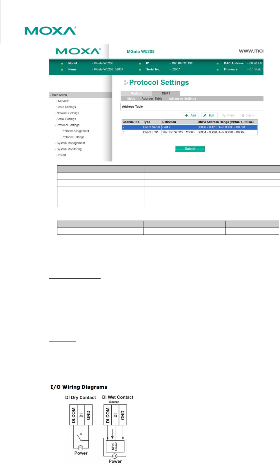
Address Table
Address Table provides user to add the destination IP address and the DNP3 start/end address for the station to be
communicated. When a DNP3 packet is received from network or serial side to the MGate, the MGate will route it to the defined
destination according to the Address Table. If the destination is on serial side, the packet is sent to the corresponding serial port.
If the destination is on network side, and the TCP connection to the destined station is already established, the DNP3 packet will
be routed to that station. If the connection is not yet established, the MGate will establish a connection to the destined station and
then send DNP3 packet to that station.
The MGate will automatically generate the setting of serial port in address table. Users have to modify the setting of serial port by
one clicking on the current shown DNP3 serial column and click Edit for modification.
--------------------------------------------------------------------------------------------------------------------------------- www.moxa.com info@moxa.com
Parameter Value Default
Remote IP address Max 40 characters null
TCP Port 1 - 65535 20000
DNP3 address start 0 – 65519 0
DNP3 address end 0 - 65519 0
DNP3 address offset -65519 ~ 65519 0
Advanced Settings
Parameter Value Default
Listen port 1 - 65535 20000
DI/DO
The MGate W5X08 is built-in with 1 digital input and 1 digital output. The I/O connection methods are listed as below.
Digital Input (Source Type)
Dry Contact level
ON State Short to GND
OFF State Open
Wet Contact level (COM to DI)
ON State +10 ~ 30VDC
OFF State 0 ~ +3V
Digital Output (Sink Type)
Driver current: Max.200 mA per Channel.
On-state voltage: Max.30 VDC
The wiring diagram is as shown below.
--------------------------------------------------------------------------------------------------------------------------------- www.moxa.com info@moxa.com
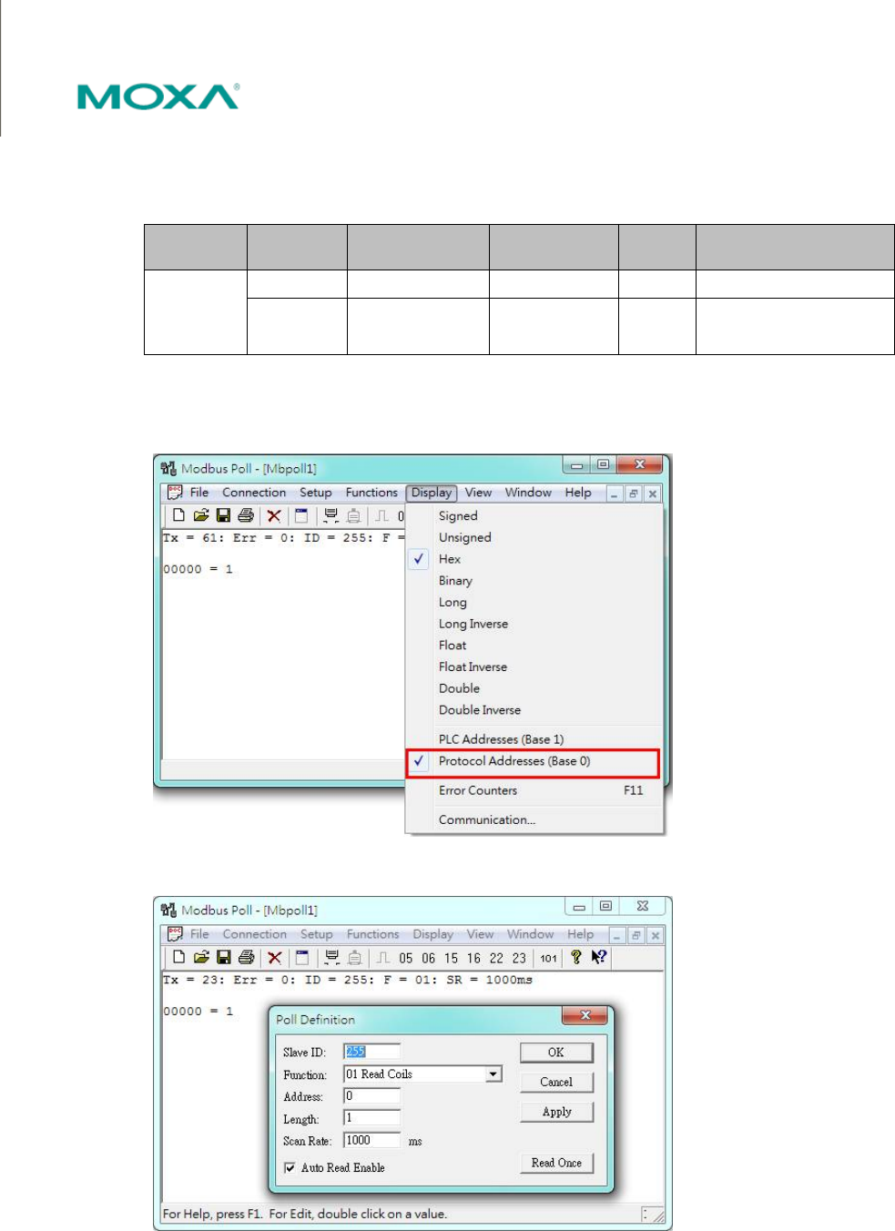
Configuration
DI/DO can be monitored and controlled through Modbus command. The related Modbus parameters are listed below. Users can
access the DI/DO through Modbus-based utility.
Slave ID DI/DO Modbus Address
(Base 0)
Modbus Address
(Base 1) Data Size
Function Code
255
DI1 0x0000 0x0001 1 bit 01: Read coils
DO1 0x0010 0x0011 1 bit
05: Write single coil
15: Write multiple coils
We use Modbus Poll shareware for demonstration.
Related settings.
DI
--------------------------------------------------------------------------------------------------------------------------------- www.moxa.com info@moxa.com
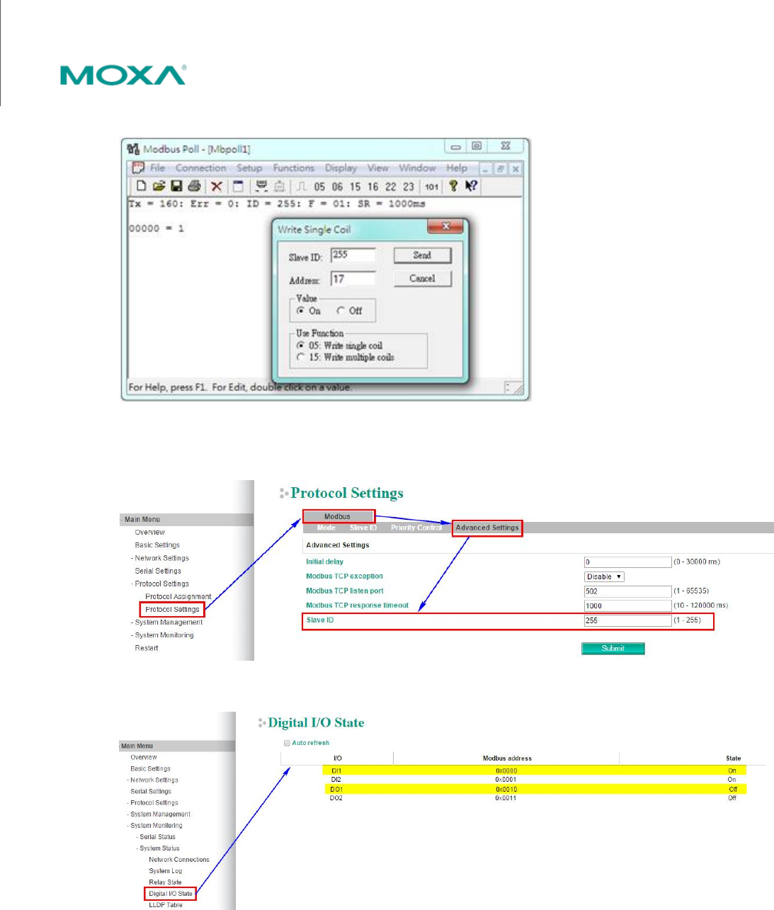
DO
Users can change the slave ID or check the status of current DI/DO values via web console.
Note that the latest version of MGate W5X08 will built-in with 2 DI and 2 DO.
--------------------------------------------------------------------------------------------------------------------------------- www.moxa.com info@moxa.com
LED Indicator
Type Color Meaning
PWR1/PWR2
Green Power is being supplied to power input PWR1,
PWR2.
Off Power is off, or power error condition exists.
Ready
Green Steady On: Power is on and the gateway is
functioning normally.
Blinking: The gateway has been located by MGate
Manager’s Location function.
Red Steady On: Power is on and gateway is booting up.
Blinking: Indicates an LAN IP conflict, or DHCP or
BOOTP server did not respond properly.
Off System power is off
Ethernet Link Green 100Mbps Ethernet connection
Amber 10Mbps Ethernet connection
Off Ethernet cable is disconnected or has a short
WLAN Green Steady on: Wireless enabled
Blinking: Indicates a WLAN IP conflict, or that the
DHCP or BOOTP server did not respond properly
RF
(signal strength)
Green 3 LED = signal strength reach between 66%~100%
2 LED = signal strength reach between 33%~66%
1 LED = signal strength reach between 0%~33%
P1/P2
(Serial signal)
Green Serial port is transmitting data
Amber Serial port is receiving data
Off No data is communicating

--------------------------------------------------------------------------------------------------------------------------------- www.moxa.com info@moxa.com
Appendix

--------------------------------------------------------------------------------------------------------------------------------- www.moxa.com info@moxa.com
D. Federal Communication Commission
Interference Statement
This equipment has been tested and found to comply with the limits for a Class B digital device, pursuant to Part 15 of the FCC Rules.
These limits are designed to provide reasonable protection against harmful interference in a residential installation. This equipment
generates, uses and can radiate radio frequency energy and, if not installed and used in accordance with the instructions, may cause
harmful interference to radio communications. However, there is no guarantee that interference will not occur in a particular
installation. If this equipment does cause harmful interference to radio or television reception, which can be determined by turning
the equipment off and on, the user is encouraged to try to correct the interference by one or more of the following measures:
• Reorient or relocate the receiving antenna.
• Increase the separation between the equipment and receiver.
• Connect the equipment into an outlet on a circuit different from that to which the receiver is connected.
• Consult the dealer or an experienced radio/TV technician for help.
CAUTION:
Any changes or modifications not expressly approved by the grantee of this device could void the user’s authority to operate the
equipment.
Labeling requirements
This device complies with Part 15 of the FCC Rules. Operation is subject to the following two conditions: (1) this device may not
cause harmful interference, and (2) this device must accept any interference received, including interference that may cause
undesired operation.
RF exposure warning
This equipment must be installed and operated in accordance with provided instructions and the antenna(s) used for this transmitter
must be installed to provide a separation distance of at least 20 cm from all persons and must not be co-located or operating in
conjunction with any other antenna or transmitter. End-users and installers must be provide with antenna installation instructions
and transmitter operating conditions for satisfying RF exposure compliance.
This radio transmitter FCCID: SLE-W5x08 has been approved by FCC to operate with the antenna types listed below
with the maximum permissible gain and required antenna impedance for each antenna type indicated. Antenna
types not included in this list, having a gain greater than the maximum gain indicated for that type, are strictly
prohibited for use with this device.
Antenna List
No.
Manufacturer Part No. Antenna Type Peak Gain
1 KINSUN 6602D03081 Dipole 1.21 dBi for 2.4 GHz
1.73 dBi for 5 GHz
Note: The antenna connector is Reverse SMA type.