Murata Electronics North America DNT90 900MHz Transceiver Module User Manual 10 0314 W06 11 A Exhibit Cover
Murata Electronics North America 900MHz Transceiver Module 10 0314 W06 11 A Exhibit Cover
Contents
- 1. Manual
- 2. manual pt a
- 3. manual pt b
Manual

5015 B.U. Bowman Drive Buford, GA 30518 USA Voice: 770-831-8048 Fax: 770-831-8598
Certification Exhibit
FCC ID: HSW-DNT90
IC: 4492A-DNT90
FCC Rule Part: 15.247
IC Radio Standards Specification: RSS-210
ACS Report Number: 10-0314.W06.11.A
Manufacturer: RFM/Cirronet
Model: DNT90C, DNT90P
Manual
www.RFM.com Technical support +1.678.684.2000 Page 1 of 86
©2010 by RF Monolithics, Inc. E-mail: tech_sup@rfm.com DNT90 Integration Guide - 10/25/10
DNT90 Series
900 MHz Spread Spectrum
Wireless Transceivers
Integration Guide

www.RFM.com Technical support +1.678.684.2000 Page 2 of 86
©2010 by RF Monolithics, Inc. E-mail: tech_sup@rfm.com DNT90 Integration Guide - 10/25/10
Important Regulatory Information
RFM Product FCC ID: HSW-DNT90
IC 4492A-DNT90
Note: This equipment has been tested and found to comply with the limits for a Class B digital
device, pursuant to Part 15 of the FCC Rules. These limits are designed to provide reasonable pro-
tection against harmful interference in a residential installation. This equipment generates, uses
and can radiate radio frequency energy and, if not installed and used in accordance with the in-
structions, may cause harmful interference to radio communications. If this equipment does
cause harmful interference to radio or television reception, which can be determined by turning
the equipment off and on, the user is encouraged to try to correct the interference by one or more
of the following measures:
1) Re-orientate or relocate the receiving antenna,
2) Increase the separation between the equipment and the radiator,
3) Connect the equipment into an outlet on a circuit different from that to which the receiver is connected,
4) Consult the dealer or an experienced radio/TV technician for help.
FCC Antenna Gain Restriction and MPE Statement:
The DNT90 has been designed to operate with any dipole antenna of up to 5.1 dBi of gain, or any Yagi of
up to 6.1 dBi gain.
The antenna(s) used for this transmitter must be installed to provide a separation distance of at least
20 cm from all persons and must not be co-located or operating in conjunction with any other antenna or
transmitter.
Industry Canada Specific Statements:
The term “IC:” before the radio certification number only signifies that Industry Canada technical specifica-
tions were met.
This Class B digital apparatus meets all requirements of the Canadian Interference Causing Equipment
Regulations. Operation is subject to the following two conditions: (1) this device may not cause harmful
interference, and (2) this device must accept any interference received, including interference that may
cause undesired operation.
Cet appareillage numérique de la classe B répond à toutes les exigences de l'interférence canadienne
causant des règlements d'équipement. L'opération est sujette aux deux conditions suivantes: (1) ce dis-
positif peut ne pas causer l'interférence nocive, et (2) ce dispositif doit accepter n'importe quelle interfé-
rence reçue, y compris l'interférence qui peut causer l'opération peu désirée.

www.RFM.com Technical support +1.678.684.2000 Page 3 of 86
©2010 by RF Monolithics, Inc. E-mail: tech_sup@rfm.com DNT90 Integration Guide - 10/25/10
IC RSS-210 Detachable Antenna Gain Restriction:
This device has been designed to operate with the antennas listed below, and having a maximum gain of
6.1 dB. Antennas not included in this list or having a gain greater than 6.1 dB are strictly prohibited for
use with this device. The required antenna impedance is 50 ohms:
RFM RWA092R Omnidirectional Dipole Antenna, 2 dBi
RFM OMNI095 Omnidirectional Dipole Antenna, 5 dBi
RFM YAGI099 Directional Antenna, 6.1 dBi
To reduce potential radio interference to other users, the antenna type and its gain should be so chosen
that the equivalent isotropically radiated power (e.i.r.p.) is not more than that permitted for successful
communication.
See Section 6.8 of this manual for regulatory notices and labeling requirements. Changes or modifica-
tions to a DNT90 not expressly approved by RFM may void the user’s authority to operate the module.

www.RFM.com Technical support +1.678.684.2000 Page 4 of 86
©2010 by RF Monolithics, Inc. E-mail: tech_sup@rfm.com DNT90 Integration Guide - 10/25/10
Table of Contents
1.0 DNT90 Introduction .......................................................................................................................... 5
1.1 Why Spread Spectrum? ............................................................................................................ 5
1.2 Frequency Hopping versus Direct Sequence ............................................................................ 6
2.0 DNT90 System Overview ................................................................................................................. 7
2.1 Point-to-Point Systems .............................................................................................................. 7
2.2 Point-to-Multipoint Systems ....................................................................................................... 8
2.3 Store-and-Forward Systems ...................................................................................................... 8
2.4 RF Channel Access ................................................................................................................... 9
2.5 DNT90 Addressing .................................................................................................................... 9
2.6 Network Linking and Slot Registration .................................................................................... 10
2.7 Transparent and Protocol-formatted Serial Data ..................................................................... 10
3.0 DNT90 Application Interfaces ........................................................................................................ 11
3.1 Serial Port ................................................................................................................................ 11
3.2 SPI Port ................................................................................................................................... 11
3.3 Digital I/O ................................................................................................................................. 14
3.4 Analog I/O ................................................................................................................................ 14
3.5 I/O Event Reporting and I/O Binding ....................................................................................... 14
4.0 DNT90 System Configuration ........................................................................................................ 15
4.1 Configuration Parameters ........................................................................................................ 15
4.2 Configuring a Basic Point-to-Point System ............................................................................. 15
4.3 Configuring a Custom Point-to-Point or Point-to-Multipoint System ....................................... 16
4.4 Configuring a Store-and-Forward System ............................................................................... 17
4.5 Coordinating Slot Sizes and Hop Duration .............................................................................. 18
5.0 DNT90 Application Interface Configuration.................................................................................... 19
5.1 Configuring the Serial Port ...................................................................................................... 20
5.2 Configuring the SPI Port .......................................................................................................... 20
5.3 Configuring Digital I/O ............................................................................................................. 20
5.4 Configuring Analog I/O ............................................................................................................ 21
5.5 Configuring I/O Event Reporting and I/O Binding .................................................................... 21
5.6 Configuring Sleep Mode .......................................................................................................... 21
6.0 DNT90 Hardware ........................................................................................................................... 23
6.1 Electrical Specifications ........................................................................................................... 24
6.2 Module Pin Out ........................................................................................................................ 25
6.3 Antenna Connector .................................................................................................................. 26
6.4 Power Supply and Input Voltages ........................................................................................... 27
6.5 ESD and Transient Protection ................................................................................................. 27
6.6 Interfacing to 5 V Logic Systems ............................................................................................. 27
6.7 Mounting and Enclosures ........................................................................................................ 27
6.8 Labeling and Notices ............................................................................................................... 28
7.0 DNT90 Protocol-formatted Messages ............................................................................................ 29
7.1 Protocol Formats ..................................................................................................................... 29
7.2 Message Types ....................................................................................................................... 29
7.3 Message Format Details .......................................................................................................... 30

www.RFM.com Technical support +1.678.684.2000 Page 5 of 86
©2010 by RF Monolithics, Inc. E-mail: tech_sup@rfm.com DNT90 Integration Guide - 10/25/10
7.4 Configuration Parameter Registers ......................................................................................... 37
7.4.1 Bank 0 - Transceiver Setup .............................................................................................. 37
7.4.2 Bank 1 - System Settings .................................................................................................. 39
7.4.3 Bank 2 - Status Parameters .............................................................................................. 40
7.4.4 Bank 3 - Serial and SPI Settings ....................................................................................... 42
7.4.5 Bank 4 - Host Protocol Settings ........................................................................................ 43
7.4.6 Bank 5 - I/O Parameters ................................................................................................... 44
7.4.7 Bank 6 - I/O Settings ......................................................................................................... 45
7.4.8 Bank FF - Special Functions ............................................................................................. 48
7.5 Protocol-formatted Message Examples .................................................................................. 49
7.5. 1 Data Message ................................................................................................................... 49
7.5.2 Configuration Message ..................................................................................................... 49
7.5.3 Event Message ................................................................................................................. 50
7.5.4 Sensor Message ............................................................................................................... 50
8.0 DNT90DK Developer’s Kit ............................................................................................................. 52
8.1 DNT90DK Kit Contents ......................................................................................................... TBD
8.2 Additional Items Needed ...................................................................................................... TBD
8.3 Developer’s Kit Default Operating Configuration .................................................................. TBD
8.4 Developer’s Kit Hardware Assembly .................................................................................... TBD
8.5 DNT90 Utility Program .......................................................................................................... TBD
8.6 Initial Kit Operation ............................................................................................................... TBD
8.6.1 Serial Communication and Radio Configuration ............................................................ TBD
8.7 DNT90 Wizard Program ....................................................................................................... TBD
8.8 DNT90 Interface Board Features ......................................................................................... TBD
9.0 Troubleshooting .......................................................................................................................... TBD
9.1 Diagnostic Port Commands .................................................................................................. TBD
10.0 Appendices ................................................................................................................................. TBD
10.1 Ordering Information ............................................................................................................. TBD
10.2 Technical Support ................................................................................................................. TBD
10.3 DNT90 Mechanical Specifications ........................................................................................ TBD
10.4 DNT90 Development Board Schematic ............................................................................... TBD
11.0 Warranty ...................................................................................................................................... TBD

www.RFM.com Technical support +1.678.684.2000 Page 6 of 86
©2010 by RF Monolithics, Inc. E-mail: tech_sup@rfm.com DNT90 Integration Guide - 10/25/10
1.0 DNT90 Introduction
DNT90 transceivers provide highly-reliable wireless connectivity for point-to-point, point-to-multipoint and
store-and-forward radio applications. Frequency hopping spread spectrum (FHSS) technology ensures
maximum resistance to multipath fading and robustness in the presence of interfering signals, while oper-
ation in the 900 MHz ISM band allows license-free use in the US, Canada, South America, Israel, Austral-
ia and New Zealand. The DNT90 supports serial data rates for host communications from 1.2 to
230.4 kbps, plus three SPI data rates from 125 to 500 kbps. On-board data buffering plus an error-
correcting radio protocol provide smooth data flow and simplify the task of integration with existing appli-
cations. Key DNT90 features include:
Multipath fading resistant frequency hopping
technology with up to 52 frequency chan-
nels, 902.76 to 927.24 MHz
Ad Hoc TDMA operating mode supports a
large number of remotes with low latency for
burst data streaming
Support for point-to-point, point-to-multipoint,
and store-and-forward networks
AES encryption provides protection from ea-
vesdropping
FCC 15.247 and IC RSS-210 certified for
license-free operation
Nonvolatile memory stores DNT90 configura-
tion when powered off
5 mile plus range with omnidirectional anten-
nas (antenna height dependent)
Selectable +16 or +22 dBm transmit power
levels
Transparent ARQ protocol with data
buffering ensures data integrity
Simple interface handles both data and con-
trol at up to 230.4 kbps on the serial port or
500 kbps on the SPI port
Analog and Digital I/O simplifies wireless
sensing
Automatic event reporting mode for I/O
simplifies application development
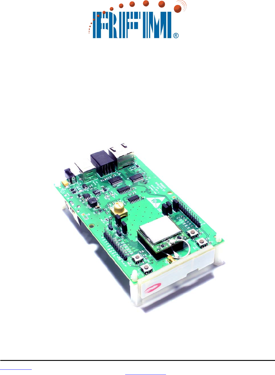
1.1 Why Spread Spectrum?
A radio channel can be very hostile, corrupted by noise, path loss and interfering transmissions from oth-
er radios. Even in an interference-free environment, radio performance faces serious degradation from a
phenomenon known as multipath fading. Multipath fading results when two or more reflected rays of the
transmitted signal arrive at the receiving antenna with opposing phases, thereby partially or completely
canceling the signal. This problem is particularly prevalent in indoor installations. In the frequency do-
main, a multipath fade can be described as a frequency-selective notch that shifts in location and intensity
over time as reflections change due to motion of the radio or objects within its range. At any given time,
multipath fades will typically occupy 1% - 2% of the band. From a probabilistic viewpoint, a conventional
radio system faces a 1% - 2% chance of signal impairment at any given time due to multipath fading.
Spread spectrum reduces the vulnerability of a radio system to both multipath fading and jammers by dis-
tributing the transmitted signal over a larger region of the frequency band than would otherwise be neces-
sary to send the information. This allows the signal to be reconstructed even though part of it may be lost
or corrupted in transmission.
www.RFM.com Technical support +1.678.684.2000 Page 7 of 86
©2010 by RF Monolithics, Inc. E-mail: tech_sup@rfm.com DNT90 Integration Guide - 10/25/10
Narrow-band versus spread spectrum transmission
Figure 1.1.1
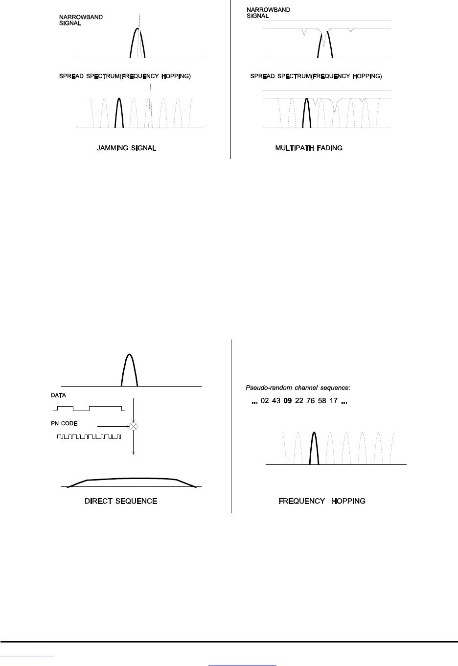
1.2 Frequency Hopping versus Direct Sequence
The two primary approaches to spread spectrum are direct sequence spread spectrum (DSSS) and fre-
quency hopping spread spectrum (FHSS), either of which can generally be adapted to a given applica-
tion. Direct sequence spread spectrum is produced by multiplying the transmitted data stream by a much
faster, noise-like repeating pattern. The ratio by which this modulating pattern exceeds the bit rate of the
base-band data is called the processing gain, and is equal to the amount of rejection the system affords
against narrow-band interference from multipath and jammers. Transmitting the data signal as usual, but
varying the carrier frequency rapidly according to a pseudo-random pattern over a broad range of chan-
nels produces a frequency hopping spectrum system.
Forms of spread spectrum - direct sequence and frequency hopping
Figure 1.1.2
www.RFM.com Technical support +1.678.684.2000 Page 8 of 86
©2010 by RF Monolithics, Inc. E-mail: tech_sup@rfm.com DNT90 Integration Guide - 10/25/10
One disadvantage of direct sequence systems is that due to design issues related to broadband transmit-
ters and receivers, they generally employ only a minimal amount of spreading, often no more than the
minimum required by the regulating agencies. For this reason, the ability of DSSS systems to overcome
fading and in-band jammers is relatively weak. By contrast, FHSS systems are capable of hopping
throughout the entire band, statistically reducing the chances that a transmission will be affected by fad-
ing or interference. This means that a FHSS system will degrade gracefully as the band gets noisier,
while a DSSS system may exhibit uneven coverage or work well until a certain point and then give out
completely.
Because it offers greater immunity to interfering signals, FHSS is often the preferred choice for co-located
systems. Since direct sequence signals are very wide, they can offer only a few non-overlapping chan-
nels, whereas multiple hoppers can interleave, minimizing interference. Frequency hopping systems do
carry some disadvantages, in that they require an initial acquisition period during which the receiver must
lock on to the moving carrier of the transmitter before any data can be sent, which typically takes several
seconds. In summary, frequency hopping systems generally feature greater coverage and channel utiliza-
tion than comparable direct sequence systems. Of course, other implementation factors such as size,
cost, power consumption and ease of implementation must also be considered before a final radio design
choice can be made.
2.0 DNT90 System Overview
A DNT90 radio can be configured to operate in one of three modes - base, remote or router. A base con-
trols a DNT90 system, and interfaces to an application host such as a PC or Internet gateway. A remote
functions to transmit or receive serial, digital (state) and analog data. A router alternates between func-
tioning as a remote on one hop and a network base on the next hop. When acting as a remote, the router
stores messages it receives from its parent, and then repeats the messages to its child radios when act-
ing as a network base. Likewise, a router will store messages received from its child radios when acting
as a base, and repeat them to its parent when acting as a remote. Any message addressed directly to a
router is processed by the router rather than being repeated.
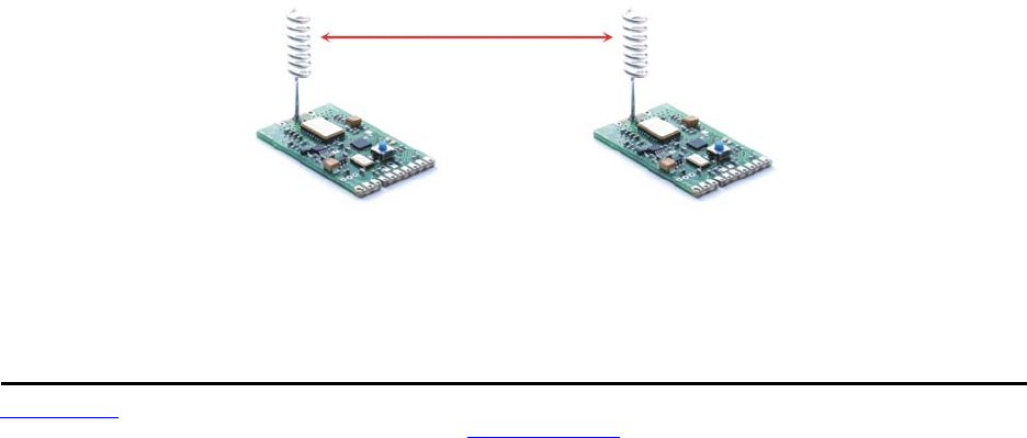
2.1 Point-to-Point Systems
A DNT90 system contains at least one network. The simplest DNT90 topology is a point-to-point system,
as shown in Figure 2.1.1. This system consists of a base and one remote forming a single network. Point-
to-point systems are often used to replace wired serial connections. Point-to-point systems are also used
to transmit switch positions or analog signals from one location to another.
Figure 2.1.1 [replace with DNT90 graphics]
www.RFM.com Technical support +1.678.684.2000 Page 9 of 86
©2010 by RF Monolithics, Inc. E-mail: tech_sup@rfm.com DNT90 Integration Guide - 10/25/10
2.2 Point-to-Multipoint Systems
Figure 2.2.1 shows the topology of a point-to-multipoint (star) system, which consists of a base and more
than one remote in a single network. Point-to-multipoint systems are typically used for data, sensor and
alarm systems. While most traffic in a point-to-multipoint system is between the base and the remotes,
DNT90 technology also allows for peer-to-peer communication from one remote to another.
Figure 2.2.1 [replace with DNT90 graphics]
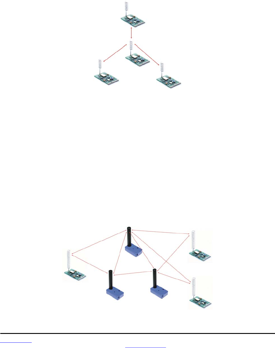
2.3 Store-and-Forward Systems
Figure 2.3.1 shows the topology of a store-and-forward system, which consists of a base, one or more
routers, one or more remotes, and two or more networks. Networks in a store-and-forward system form
around the base and each router. The base and the routers are referred to as the parents of the networks
they form. The rest of the radios in each network are referred to as child radios. Note that a router can be
a child of the base or another router while being the parent of its own network. Each network parent
transmits beacons to allow child radios to synchronize with its hopping pattern and join its network. Differ-
ent frequency hopping patterns are used by the parent radios in a system, minimizing interference be-
tween networks.
Store-and-forward systems are used to cover larger areas than is possible with point-to-point or point to-
multipoint systems. The trade-off in store-and-forward systems is longer delivery times due to receiving
and retransmitting a message several times. Store-and-forward systems are especially useful in applica-
tions such as agriculture where data is only collected every hour or so.
Figure 2.3.1 [replace with DNT90 graphics]

www.RFM.com Technical support +1.678.684.2000 Page 10 of 86
©2010 by RF Monolithics, Inc. E-mail: tech_sup@rfm.com DNT90 Integration Guide - 10/25/10
2.4 RF Channel Access
The time a DNT90 network stays on each frequency in its hopping pattern is called the hop duration or
dwell time, which can be configured from 8 to 100 ms. Radio communication during each dwell is orga-
nized as a time division multiple access (TDMA) frame. A DNT90 frame begins with a base-mode beacon,
followed by 1 to 8 time slots used by the network children to transmit to their parent, as shown in Figure
2.4.1. A base-mode beacon can include up to 8 messages addressed to one or more child radios.
S y s t e m / N e t w o r k
C o n t r o l
M e s s a g e s t o
N e t w o r k C h i l d r e n
O p e n
S l o t
O p e n
S l o t
A s s i g n e d
S l o t
S l o t s
B a s e - M o d e
B e a c o n
D N T 9 0 C o m m u n i c a t i o n F r a m e
Figure 2.4.1
Each beacon includes the status of all slots - either registered (assigned) or open. When a child radio has
information to transmit to its parent, it randomly selects one of the open slots and transmits all or the first
part of its data. If the parent successfully receives the transmission, it includes the child’s MAC address in
the next beacon. This signals the child radio that the slot is temporarily registered to it, allowing the child
to efficiently stream any remaining data to the base hop-by-hop until it is all sent.
If a child radio does not see its address in the next beacon following its transmission, it again randomly
selects an open slot and retransmit its data. During times when there are no open slots, a child radio
keeps its data queued and continues to look for an open slot in each beacon until at least one slot be-
comes available. The access method the DNT90 uses is referred to as Ad Hoc TDMA or hybrid
CSMA/TDMA.
2.5 DNT90 Addressing
Each DNT90 has a unique MAC address. The MAC address can be read or bar-code scanned from the
label on top of each radio. A DNT90 radio in any mode (base/router/remote) can be addressed using its
MAC address. A DNT90 base can be addressed using either its MAC address or address 0x000000. A
DNT90 can send a message to all other DNT90’s in its system by using the broadcast address
0xFFFFFF.
The base and all routers (parents) hold a base-mode network ID, which is transmitted in every beacon. All
routers and remotes hold a parent network ID and optionally an alternate parent network ID to compare
against the base-mode network IDs in the beacons they receive. A child router or remote is allowed to
join a parent if its parent network ID or alternate parent network ID matches the parent’s base-mode net-
work ID, or with any parent when its parent network ID is set to 0xFF (wildcard).
In a point-to-point or point-to-multipoint system, the default base-mode network ID of 0xFF (wildcard) can
be used. In a store-and-forward system, however, the base-mode network IDs of all routers must be set
to different values between 0x00 to 0x3F. If the base-mode network ID of 0x00 is assigned to a router, the
base must be assigned an unused base-mode network ID between 0x01 and 0x3F.

www.RFM.com Technical support +1.678.684.2000 Page 11 of 86
©2010 by RF Monolithics, Inc. E-mail: tech_sup@rfm.com DNT90 Integration Guide - 10/25/10
Leaving all parent network IDs in a store-and-forward system set to the default value of 0xFF allows net-
works to automatically form, and self-repair if a parent router fails. Enabling the alternate parent network
ID also provides self-repairing message routing.
All DNT90 radios hold a system ID that can be used to distinguish systems that physically overlap. In a
DNT90 system, the system ID must be different from those used by overlapping systems to provide mes-
sage filtering. Also, using different base-mode network IDs for all networks in overlapping systems helps
reduce hopping pattern collisions.
The store-and-forward path between the base and any other radio in a system can be determined by
reading the radio’s ParentMacAddress parameter. If this address is not the base, then reading the Pa-
rentMacAddress parameter of its parent, grandparent, etc., in succession reveals the complete path to
the base. Path determination is useful in optimizing and troubleshooting systems during commissioning
and maintenance.
2.6 Network Linking and Slot Registration
When first turned on, a DNT90 router or remote rapidly scans all frequency channels in its operating band
to acquire synchronization and link to a parent based on a system ID match plus a base-mode network ID
to parent network ID/alternate parent network ID match (or by using a wildcard (0xFF) parent network ID).
In addition to the slot status and the MAC addresses of child radios holding slot registrations, each base-
mode beacon includes one of a number of cycled control parameters. The cycled parameters are col-
lected by child radios, allowing them to register with a parent, and to later follow any control parameter
changes. When a router or remote has collected a full set of cycled parameters, it can issue an optional
initial heartbeat message and then optional periodic heartbeat messages which allow an application to
maintain the status of all routers and remotes in its DNT90 system.
When a router/remote has data to send to its parent, it picks an open slot at random and transmits. It then
looks for its MAC address in the next beacon. If its MAC address is present in the beacon, it is temporarily
registered to the slot and continues to use it until all current data is sent, or its MAC address drops off the
beacon (link lost).
2.7 Transparent and Protocol-formatted Serial Data
A DNT90 remote can directly input and output data bytes and data strings on its serial port. This is re-
ferred to as transparent serial port operation. In a point-to-point system, the base can also be configured
for transparent serial port operation.
In all other cases, serial data must be protocol formatted:
- configuration commands and replies
- I/O event messages
- announcement messages including heartbeats
Protocol-formatted messages are discussed in detail in Section 7. Briefly, protocol-formatted messages
include a start-of-messages character, message length and message type information, the destination
address of the message, and the message payload.
www.RFM.com Technical support +1.678.684.2000 Page 12 of 86
©2010 by RF Monolithics, Inc. E-mail: tech_sup@rfm.com DNT90 Integration Guide - 10/25/10
Transparent data is routed using a remote transparent destination address. In a remote, this address de-
faults to the base, 0x000000, and in the base this address defaults to broadcast, 0xFFFFFF. These de-
faults can be overridden with specific radio addresses. For example, it is possible to set up transparent
peer-to-peer routing between two remotes in a point-to-multipoint or store-and-forward system by loading
specific MAC addresses in each radio’s remote transparent destination address.
3.0 DNT90 Application Interfaces
A DNT90 module provides a variety of application interfaces including a serial port, SPI port, six digital I/O
ports (logic state), three 12-bit ADC input ports, and two 12-bit DAC output ports. Each of these interfaces
is discussed below.
3.1 Serial Port
The DNT90 serial port is a full-duplex UART interface with hardware flow control on two of the digital I/O
pins as a default feature. One digital I/O pin can also be configure as an RS485 enable function. The
serial port can be configured with baud rates from 1.2 to 230.4 kbps, with 9.6 kbps the default baud rate.
The DNT90 serial port transmits/receives 8-bit data with a choice of even/odd/no parity and 1 or 2 stop
bits. The default configuration is no parity and one stop bit. See Section 5.1 for recommendations on con-
figuring the serial port, and Section 7.4.4 for detailed information on serial port configuration parameters.
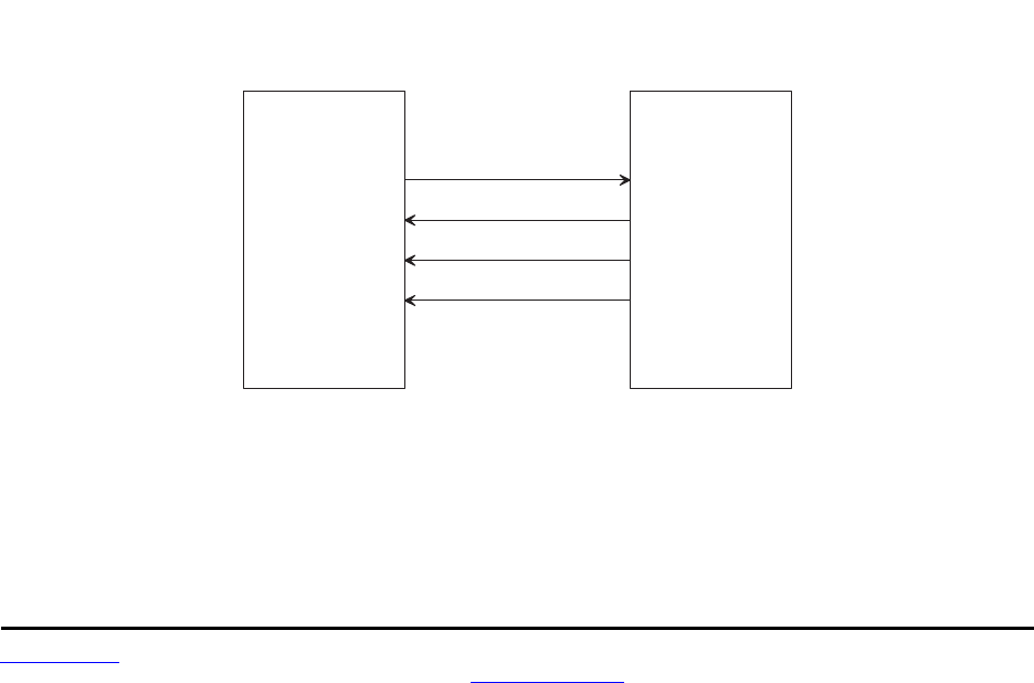
3.2 SPI Port
The DNT90 serial peripheral interface (SPI) port can operate either as a master or a slave. The port
includes the four standard SPI connections - MISO, MOSI, SCLK and /SS, plus three signals used to
support SPI slave mode operation - /HOST_RTS, /HOST_CTS and DAV. The serial port and SPI master
mode can run simultaneously. Serial port operation is disabled when the SPI port is configure for slave
mode. Note that all SPI slave mode messages must be protocol formatted.
D N T 9 0P e r i p h e r a l
D N T 9 0 S P I M a s t e r M o d e S i g n a l i n g
/ S S
S C L K
M O S I
M I S O
Figure 3.2.1
www.RFM.com Technical support +1.678.684.2000 Page 13 of 86
©2010 by RF Monolithics, Inc. E-mail: tech_sup@rfm.com DNT90 Integration Guide - 10/25/10
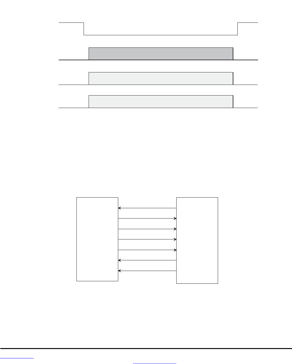
The DNT90 SPI port can run at three clock rates in master mode - 125, 250 or 500 kbps. There are two
message sources available to a DNT90 SPI master, a protocol-formatted RxData message, or a stored
command. The DNT90 master will clock a message from either source into its slave and return the bytes
clocked out as a protocol-formatted TxData message. The DNT90 event timer triggers sending the stored
command to the DNT90’s slave. The stored command can be up to 16 bytes in length. Figure 3.2.1
shows the required SPI master mode-signal connections, and Figure 3.2.2 shows the SPI master-mode
timing.
/ S S
S C L K
M I S O
M O S I
S P I B i t C l o c k
C o m m a n d t o S l a v e
D a t a f r o m S l a v e
D N T 9 0 S P I M a s t e r M o d e O p e r a t i o n
Figure 3.2.2
In SPI slave mode, the host can stream data into DNT90 at up to 250 kbps, provided the host suspends
clocking within 10 bytes following a low-to-high transition on /HOST_CTS. The host can clock data into
the DNT90 at up to 4 Mbps for data bursts of up to 50 bytes, provided the interval from the end of one
burst to the start of the next burst is at least 2 ms, and the host suspends clocking on a low-to-high transi-
tion on /HOST_CTS. See Figure 3.2.4
D N T 9 0H o s t
D N T 9 0 S P I S l a v e M o d e S i g n a l i n g
/ S S
S C L K
M O S I
M I S O
/ H O S T _ C T S
DAV
/ H O S T _ R T S
Figure 3.2.3
www.RFM.com Technical support +1.678.684.2000 Page 14 of 86
©2010 by RF Monolithics, Inc. E-mail: tech_sup@rfm.com DNT90 Integration Guide - 10/25/10
/ S S
/ H O S T _ C T S
S C L K
M O S I
S P I B i t C l o c k
M e s s a g e t o D N T 9 0
D N T 9 0 S P I S l a v e M o d e M e s s a g e L o a d
Figure 3.2.4
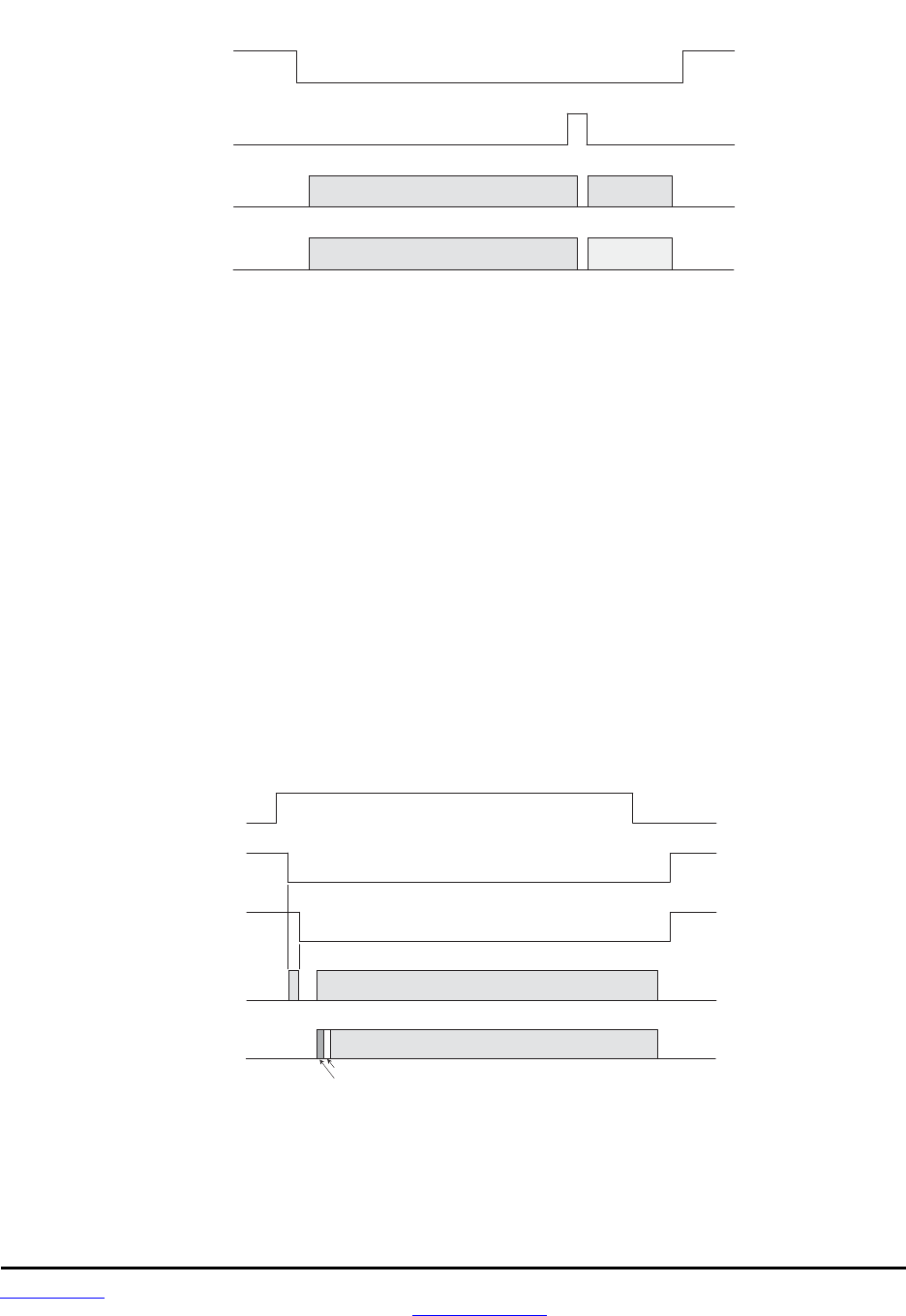
The host should use the following steps to fetch data from a DNT90 SPI slave, as show in Figure 3.2.5:
1. The host sets the /HOST_RTS signal high to allow the DNT90 to signal data available.
2. The DNT90 sets the data available (DAV) high to signal the host it has data.
3. The host set the /SS signal low to enable SPI operation.
4. The host clocks in one dummy byte (ignore the output byte) and then sets /HOST_RTS low.
5. The host begins to clock out the data, which can include several messages.
6. The host continues to clock out data until a 0x00 byte occurs in the byte stream where a 0xFB
start-of-message would be expected.
7. The host has now clocked out all messages and the 0x00 is discarded.
8. The host sets /HOST_RTS and /SS high to allow the DNT90 to signal DAV the next time it
has data.
Note that the DAV signal can go low before the last message is clocked out. It is not a reliable indication
that the last byte of the message(s) has been clocked out. See Section 5.2 for recommendations on con-
figuring the SPI port, and Section 7.4.4 for detailed information on SPI port configuration parameters.
/ S S
DAV
S C L K
M I S O
S P I C l o c k
P r o t o c o l F o r m a t t e d R X M e s s a g e
D N T 9 0 S P I S l a v e M o d e R X M e s s a g e R e t r i e v a l
L e n g t h B y t e
0 x F B S t a r t o f M e s s a g e
/ H O S T _ R T S
Figure 3.2.5

www.RFM.com Technical support +1.678.684.2000 Page 15 of 86
©2010 by RF Monolithics, Inc. E-mail: tech_sup@rfm.com DNT90 Integration Guide - 10/25/10
3.3 Digital I/O
The DNT90’s six digital (state) I/O ports are labeled GPIO0 through GPIO5. GPIO5 defaults to /HOST_
RTS and GPIO4 defaults to /HOST_CTS, providing hardware handshaking for the serial port and SPI
slave mode operation. If serial port hardware handshaking is not required and SPI slave mode is not
enabled, GPIO4 and GPIO5 can be used for other digital I/O functions. When SPI slave mode is enabled,
GPIO5 and GPIO4 must be used for /HOST_RTS and /HOST_CTS respectively, and GPIO3 must be
used to provide the DAV signal (SPI slave mode overrides any other configuration for these ports). Ex-
cept in SPI slave mode, GPIO0 through GPIO3 and optionally GPIO4 and GPIO5 are available for cus-
tomer-defined functions:
- The direction of each GPIO pin can be set for both active and sleep modes.
- The initial state (power on) of all GPIO pins configured as outputs can be set.
- The state of all GPIO pins configured as outputs in sleep mode can be set.
- GPIO triggering of I/O event reporting can be configured.
- GPIO level control of sleep hold-off can be configured.
See Section 5.3 for recommendations on configuring the digital I/O, and Sections 7.4.6 and 7.4.7 for de-
tailed information on GPIO parameters.
3.4 Analog I/O
The DNT90’s three ADC inputs are labeled ADC0 through ADC2. The ADCs can be disabled if unused to
reduce current consumption. ADC measurements are made with 12-bit resolution. There are three op-
tions for the ADC full-scale reference:
1. The DNT90 regulated buss voltage divided by 1.6 or about 2.06 V
2. An internal band-gap reference voltage, 1.00 V nominal
3. A voltage supplied to the DNT90’s ADC_EXT_REF input pin, 2.70 V maximum. If no connection
is made to this pin, a voltage equal to about 1/2 the buss voltage will be present.
The three ADCs are read each ADC sample interval, which is configurable. High and low measurement
thresholds can be set for each ADC input to trigger I/O event reporting messages.
The DNT90’s two DAC outputs are labeled DAC0 and DAC1. The DACs can be disabled if unused to re-
duce current consumption. The DAC settings have 12-bit resolution. There are three options for the DAC
full-scale reference:
1. The DNT90 regulated buss voltage, about 3.3 V
2. An internal band-gap reference voltage, 1.00 V nominal
3. A voltage supplied to the DNT90’s ADC_EXT_REF input pin, 2.70 V maximum. If no connection
is made to this pin, a voltage equal to about 1/2 the buss voltage will be present.
See Section 5.4 for recommendations on configuring the analog I/O, and Sections 7.4.6 and 7.4.7 for de-
tailed information on analog I/O parameters.
3.5 I/O Event Reporting and I/O Binding
The DNT90’s I/O event reporting function can generate a protocol-formatted RxEvent message when
triggered by one of the following I/O events:

www.RFM.com Technical support +1.678.684.2000 Page 16 of 86
©2010 by RF Monolithics, Inc. E-mail: tech_sup@rfm.com DNT90 Integration Guide - 10/25/10
- A specific state change of GPIO0, GPIO1, GPIO2 or GPIO3.
- Firing of the periodic event report timer.
- A high or low threshold exceeded on a measurement by ADC0, ADC1 or ADC2.
An I/O report message includes:
- The states of GPIO0 through GPIO5.
- The latest measurements made by ADC0 through ADC2 .
- A set of flags indicating which event(s) triggered the I/O report.
- The settings of DAC0 and DAC1.
The I/O binding function works in conjunction with I/O event reporting. When I/O binding is enabled on a
DNT90, data received in an I/O event report it is mapped as follows:
- GPIO2 will output the state of GPIO0 in the last received event report.
- GPIO3 will output the state of GPIO1 in the last received event report.
- DAC0 will output the voltage read by ADC0 in the last received event report.
- DAC1 will output the voltage read by ADC1 in the last received event report.
I/O binding is used to transmit switch positions or analog signals from one location to another. Note that
I/O binding cannot be used in a DNT90 when SPI slave mode is enabled. See Section 5.4 for recommen-
dations on configuring I/O event reporting and binding, and Sections 7.4.6 and 7.4.7 for detailed informa-
tion on I/O reporting and binding parameters.
4.0 DNT90 System Configuration
DNT90 radios feature an extensive set of configuration options that allows them to be adapted to a wide
range of applications. Configuration defaults have been carefully selected to minimize the configuration
effort for most applications, while providing the ability to individually adjust the configuration of each radio
to achieve highly optimized system operation.
4.1 Configuration Parameters
The configuration of a DNT90 is controlled by a set of parameters (registers). Parameters that address a
particular aspect of operation are grouped into a bank. All parameters can be accessed through a mod-
ule’s serial port and over the radio link. Most parameters are read/write. Read-only parameters include
fixed values such a MAC addresses, firmware version numbers and parameters that are dynamically ad-
justed during system operation such as link status. Write-only parameters include security keys and cer-
tain action triggers such as reset. Incorrectly configuring certain parameters can disable a module’s radio
link, but the configuration can always be corrected through the serial port. The organization of the para-
meter register banks and the details of each parameter are covered in Section 7.4 of this guide. Sections
4.2 through 5.7 discuss which parameters apply to various aspects of configuring a DNT90 system, net-
work or application interface.
4.2 Configuring a Basic Point-to-Point System
A basic DNT90 point-to-point systems is suitable for many serial data applications. The default confi-
guration of a DNT90 is a remote with the serial port configured for transparent operation at 9.6 kbps,
8N1. To configure a basic point-to-point system:
1. Configure one of the modules as a base by setting the DeviceMode parameter in Bank 0 to 0x01.

www.RFM.com Technical support +1.678.684.2000 Page 17 of 86
©2010 by RF Monolithics, Inc. E-mail: tech_sup@rfm.com DNT90 Integration Guide - 10/25/10
2. Set the MemorySave parameter in Bank 0xFF to 0xD2, which will save the DeviceMode parame-
ter to EEPROM and reset the module, enabling base operation.
3. All other parameters may be left at their default values.
4.3 Configuring a Custom Point-to-Point or Point-to-Multipoint System
To configure a customized point-to-point system or a point-to-multipoint system, RFM recommends the
following configuration sequence:
1. Configure one of the modules as a base by setting the DeviceMode parameter in Bank 0 to 0x01.
2. Set the AES security key in all system radios by loading your selected 16-byte string into the
SecurityKey parameter in Bank 0 (the default is 16 bytes of 0x00).
3. Select the frequency band of operation by setting the FrequencyBand parameter in Bank 1 of the
base radio as desired (the default is Bank 0).
4. Set the transmitter power level as needed in all radios by setting the TxPower parameter in
Bank 0 (the default is 40 mW).
5. Configure the system ID in all radios by setting the SystemID parameter in Bank 0 (the default OK
if there is no chance of overlapping systems).
6. Load the parent network ID in all remotes in the ParentNetworkID parameter in Bank 0 as needed
(wildcard default is OK for point-to-point and point-to-multipoint systems).
7. Set the BaseModeNetID parameter in the base to match the ParentNetworkID parameter in the
remotes.
8. For a point-to-multipoint system, set the ProtocolMode parameter in Bank 4 of the base to 0x01.
Set the protocol mode as needed in the base and remote of a point-to-point system, and as
needed in the remotes in a point-to-multipoint system. If SPI slave mode will be used, protocol
mode must be enabled in all system radios.
9. If using transparent serial mode in the system:
a. Set the remote transparent destination address in the RmtTransDestAddr parameter,
Bank 0, in each remote (the base address is the default destination).
b. Set the transparent point-to-point mode to select either the RmtTransDestAddr address
(default) or the address of the originator of the last received message as the remote des-
tination address. The parameter that controls this destination address is the Trans-
PtToPtMode in Bank 4. Set in all remotes as needed.
c. Set the timeout for transmission of transparent data in the remotes as needed. The pa-
rameter that controls the timeout is the TxTimeout in Bank 4 (the default is no timeout).
d. Set the minimum message length for transmission of transparent data in the remotes as
needed. The parameter that controls the length is the MinPacketLength in Bank 4 (the
default is one byte).
10. Set the maximum number of messages that can be sent in a frame in each system radio. The pa-
rameter that controls this number is MaxDataPackets in Bank 4 (the default is 8 messages ).

www.RFM.com Technical support +1.678.684.2000 Page 18 of 86
©2010 by RF Monolithics, Inc. E-mail: tech_sup@rfm.com DNT90 Integration Guide - 10/25/10
11. Load the required base slot size into the BaseSlotSize parameter, Bank 1, in the base. The de-
fault is 40 bytes. See Section 4.5 below.
12. Configure the number of slots per frame on the base by setting the NumSlots parameter (the de-
fault is 3 slots). See Section 4.5 below.
13. Set the required hop duration on the base. The HopDuration parameter in Bank 0 controls hop
duration. The default is 20 ms. See Section 4.5 below.
14. Configure the slot lease on the base by setting the SlotLease parameter. The default is 4 hops.
15. Set the heartbeat interval as required in each system radio. The parameter that controls heart-
beats is the HeartBeatIntrvl in Bank 0. The default is 20 seconds/heartbeat.
16. Enable message ACKs where required by setting the AckEnable parameter in Bank 0 to 1. The
default is ACKs disabled.
17. Set the message retry limit on the base with the ArqAttemptLimit parameter in Bank 1. The de-
fault value is 4 retries.
18. Configure the link drop threshold on the base by setting the LinkDropThreshold in Bank 1 (the de-
fault is 10 hops).
19. Set the point-to-point reply timeout on the base in the P2PReplyTimeout parameter in Bank 1.
The default is 16 hops.
20. Configure the registration timeout on the base by setting the RegistryTimeout parameter in
Bank 1 (the default timeout is 50 hops).
21. Load an optional “friendly description” in each system radio in the UserTag parameter, Bank 0.
4.4 Configuring a Store-and-Forward System
The following additional parameters must be set to configure a DNT90 store-and-forward system:
1. Configure the DNT90 radios designated to be routers by setting the DeviceMode parameter
in Bank 0 to 0x02.
2. Enable store-and-forward operation on all system radios by setting the Store&ForwardEn
parameter in Bank 0 to 0x01.
3. In each router, load a unique base-mode network ID into the BaseModeNetID parameter in Bank
0, and into the base if a router is set to 0x00.
4. To configure the system topology manually, set the parent network ID parameter, ParentNwkID,
and optionally the alternate parent network ID parameter, AltParentNwkID, in all routers and
remotes. Note that a store-and-forward system topology can be formed either automatically or
manually, based on the settings of the ParentNetworkID and optionally the AltParentNwkID
parameters:
- Setting the ParentNwkID parameter to 0xFF in all routers and remotes allows each rou-
ter and remote to automatically link to a parent, causing the system to form

www.RFM.com Technical support +1.678.684.2000 Page 19 of 86
©2010 by RF Monolithics, Inc. E-mail: tech_sup@rfm.com DNT90 Integration Guide - 10/25/10
automatically (child routers picking each other as a parent cannot occur). In this case, the
AltParent-NwkID parameter should be set to 0xFF, which disables it.
- Setting the ParentNwkID and optionally the AltParentNwkID parameters to specific val-
ues in each router and remote allows full manual control of the network topology.
The benefit of automatic system formation is self-healing. If a parent router fails, its child nodes
can re-link to any other parent router they can receive. However, automatic topology formation
can result in an unnecessary number of hops between routers or remotes and the base.
The benefit of manual system topology formation is to avoid unnecessary extra hops in the sys-
tem, and to balance the number of children supported by each parent router. If a parent router
fails and an active alternate parent network ID has not been assigned, all children downstream
from the failure will be off the system until the failed router is repaired or replaced.
4.5 Coordinating Slot Sizes and Hop Duration
The base slot size (BSS) is the maximum number of payload bytes the base can transmit during a single
hop, when the base is sending one message per hop. The maximum BSS is 105 bytes when a DNT90
system is configured for one slot. Adding additional slots reduces the maximum BSS by three bytes per
slot. The base transmit buffer is set nine bytes larger than the BSS, to a maximum of 114 bytes. The base
can potentially send more than one message per beacon. Each message in the transmit buffer occupies
nine header bytes plus the payload.
For example, the base can send three messages per hop when the BSS is 90 bytes, provided the total
payload bytes in the three messages is 72 bytes or less:
slot size = 90
TX buffer = 90 + 9 = 99
3 headers = 3*9 = 27
net for payload = 99 - 27 = 72
The BSS must be large enough to accommodate all protocol-formatted messages that may be sent over
the wireless link, as these messages must be sent in a single transmission.
The size of all (child) slots in a hop frame is the same, and is referred to as the remote slot size (RSS).
The RSS is calculated by all DNT90s in a system. The slot size depends on the current values of the fol-
lowing parameters:
- base slot size
- hop duration
-number of slots in a frame
The user must be able to configure the system so that the RSS will accommodate all protocol-formatted
message that may be sent over the wireless link. This is done by setting the appropriate hop duration for
the chosen BSS and number of slots. The required hop duration for a specific number of slots, base slot
size and remote slot size is calculated as follows:

www.RFM.com Technical support +1.678.684.2000 Page 20 of 86
©2010 by RF Monolithics, Inc. E-mail: tech_sup@rfm.com DNT90 Integration Guide - 10/25/10
HD hop duration in µs
NS number of slots
BSS base slot size in bytes
RSS remote slot size in bytes
HD = NS*(80*RSS + 2440) + 80*BSS + 3280
(round HD up to an even multiple of 500 µs)
Example:
NS = 4
BSS = 96
RSS = 109
HD = 4*(80*109 + 2440) + 80*96 + 3280
HD = 44640 + 7680 + 3280
HD = 55600 round to 56000 µs = 56 ms
Excel Formatted Equations:
A B C D E
1 Slots BSS RSS Hop Duration in µs Hop Duration in ms, Rounded
2 Up to the next 0.5 ms Step
3 1 20 20 =A3*(80*C3+2440) + 80*B3 + 3280 =0.5*QUOTIENT((D3+499),500)
For transparent serial port operation, the BSS and RSS must be large enough to accommodate all mes-
sage bytes that can accumulate between transmissions. As discussed above, the number of message
bytes is controlled by the MinPacketLength parameter setting. The required BSS and RSS for protocol-
formatted messages sent over the wireless link are shown in Table 7.3.1. For example, the BSS and RSS
size required for a TxData protocol-formatted message is three bytes less than the value in the length
byte field of the formatted message.
The default BSS is 40 bytes, number of slots is 3 and hop duration is 20 ms. These parameter settings
provide a 25 byte RSS. These default settings are suitable for point-to-point and small to medium point-
to-multipoint systems operating with protocol-formatted and/or transparent messages. To accommodate
all configuration commands, replies, event messages and announce messages, a 20 byte minimum slot
size is required.
5.0 DNT90 Application Interface Configuration
DNT90 modules include a comprehensive set of application interfaces and related options that support a
wide range of applications including wireless RS232/485 cable replacements, wireless sensor networks,
wireless alarm systems and industrial remote control applications. Recommended configuration steps for
each application interface are discussed in Sections 5.1 through 5.7 below.

www.RFM.com Technical support +1.678.684.2000 Page 21 of 86
©2010 by RF Monolithics, Inc. E-mail: tech_sup@rfm.com DNT90 Integration Guide - 10/25/10
5.1 Configuring the Serial Port
The default serial port configuration is 9.6 kbps, 8-bit data, no parity and 1 stop bit.
1. Configure the serial data rate as required from 1.2 to 230.4 kbps by setting the SerialRate
parameter in Bank 3.
2. Configure the parity and number of stop bits by setting the SerialParams parameter in Bank 3.
3. Enable/disable serial port handshaking as required by setting the GpioAlt parameter in Bank 6.
Handshaking is enabled by default, and is recommended for data rates 9.6 kbps and higher.
5.2 Configuring the SPI Port
1. Enable either SPI master mode or SPI slave mode by setting the SpiMode parameter in Bank 3.
Note that SPI slave mode disables serial port operation.
2. If using SPI master mode:
a. Select the SPI clock rate by setting the SpiRateSel parameter in Bank 3 (default
is 125 kbps)
b. Set the SPI master command string and string length by setting the SpiMasterCmdStr
and SpiMasterCmdLen parameters respectively in Bank 3.
3. Configure the edge trigger direction, bit-sampling edge and bit-order options by setting the
SpiOptions parameter in Bank 3.
5.3 Configuring Digital I/O
1. GPIO2 through GPIO 5 have configurable alternate functions as discussed in Section 7.4.7. Se-
lect either digital (state) functionality or alternate functionality for each of these pins by setting the
GpioAlt parameter in Bank 6. Note that selecting SPI slave mode overrides the GpioAlt parameter
setting for GPIO3 though GPIO5.
2. Configure the direction of each GPIO pin as needed by setting the GpioDir parameter in Bank 6
(the default is all inputs).
3. Configure the direction of each GPIO pin for sleep mode as needed by setting the GpioSleepDir
parameter in Bank 6 (the default is all inputs).
4. Set the initial state (power on) of all GPIO pins configured as outputs by setting the GpioInit pa-
rameter in Bank 6 (the default is all logic low).
5. Set the state of all GPIO pins configured as outputs in sleep mode by setting the GpioSleepState
parameter in Bank 6 (the default is all logic low).
6. GPIO0 through GPIO3 can trigger I/O event reporting when functioning as digital inputs. Enable
event report triggering and optional sleep hold-off for these pins by setting the GpioEdgeTrigger
parameter in Bank 6.

www.RFM.com Technical support +1.678.684.2000 Page 22 of 86
©2010 by RF Monolithics, Inc. E-mail: tech_sup@rfm.com DNT90 Integration Guide - 10/25/10
5.4 Configuring Analog I/O
1. Select the ADC full scale reference by setting the AdcReference parameter in Bank 6. This set-
ting applies to all ADC channels. The default is the ADC_EXT_REF input. If ADC operation is not
needed, setting this parameter to 0x03 disables ADC operation, reducing current consumption.
2. Configure the ADC measurement interval by setting the AdcSampleIntvl parameter. The default is
10 ms, and applies to all ADC channels.
3. Measurements on each ADC input can be compared to high/low threshold values, triggering an
I/O event report if the measurements go above/below the respective thresholds. The thresholds
for each ADC channel are set by loading the AdcXThresholdLo and AdcXThresholdHi, where X
refers to the ADC channel designator, 0 through 2.
4. Select the DAC full scale reference by setting the DacReference parameter in Bank 6. This set-
ting applies to both DAC channels. The default is the ADC_EXT_REF input. If DAC operation is
not needed, setting this parameter to 0x03 will disable DAC operation, reducing current consump-
tion.
5. Configure the initial (power on) output level for DAC0 and DAC1 by loading the initial settings in
the Dac0Init and Dac1Init parameters respectively.
5.6 Configuring I/O Event Reporting and I/O Binding
1. Select the analog, digital and timing events that will trigger an I/O event report by setting the
respective bits in the IoReportTrigger parameter in Bank 6. The default is no triggers set.
2. Configure the trigger behavior bits in the GpioEdgeTrigger parameter, Bank 6, for each GPIO
input selected to generate an I/O event report.
3. For each ADC channel selected to generate an I/O event, set the high and low measurement
threshold values. The AdcThreshold parameters are in Bank 6 at register offsets 15, 17, 19, 21,
23 and 25.
4. If the periodic timer has been selected to generate an event report, load the required timer report
interval into the IoReportInterval parameter in Bank 6. The default timer interval is 30 seconds.
5. The ReportHoldoff parameter in Bank 6 sets the delay following an event to take ADC readings
for the I/O event report. The parameter scaling is in milliseconds, and the default is 0. Set this pa-
rameter as required to avoid transient interference with the ADC measurements.
6. If I/O binding operation is desired, set the IoBindingEnable parameter in Bank 6 to 0x01. I/O
binding is disabled by default.
5.6 Configuring Sleep Mode
Sleep mode can be used in conjunction with I/O reporting to greatly extend battery life on DNT90 re-
motes. At least one I/O report trigger must be enabled to allow sleep mode to be used. Note that the
base and routers cannot be configured for sleep mode.

www.RFM.com Technical support +1.678.684.2000 Page 23 of 86
©2010 by RF Monolithics, Inc. E-mail: tech_sup@rfm.com DNT90 Integration Guide - 10/25/10
1. Enable sleep mode as desired in each remote by setting the SleepModeEn parameter in Bank 0 to 1.
2. Configure the timeout for a remote to attempt to link to its parent when triggered awake. This is done
by setting the WakeLinkTimeout parameter in Bank 0. The default timeout is 5 seconds.
3. Configure the maximum time a remote in sleep mode will remain awake following linking, receiving an
ACK, processing a message addressed to it, or receiving a serial or SPI message by setting the
Wake-ResponseTime parameter. The default response time is 500 ms. Note that the setting of this
parameter is overridden by some GpioEdgeTrigger parameter settings.
www.RFM.com Technical support +1.678.684.2000 Page 24 of 86
©2010 by RF Monolithics, Inc. E-mail: tech_sup@rfm.com DNT90 Integration Guide - 10/25/10
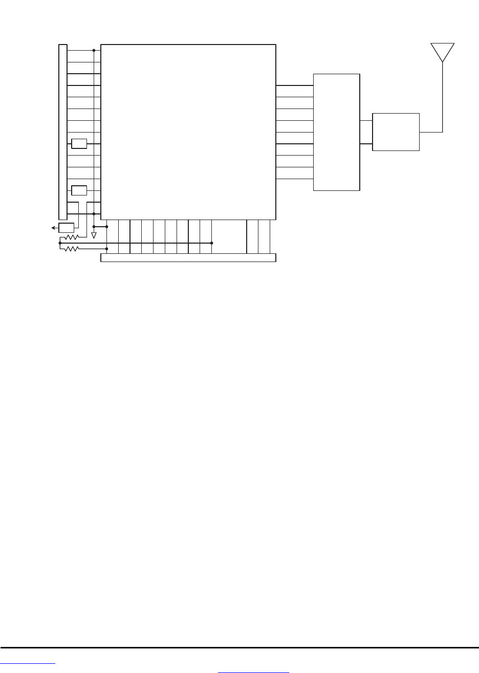
6.0 DNT90 Hardware
1 8 1 9 2 0 2 1 2 2 2 31 71 6 2 4 2 5 2 6
1 5
1 4
1 3
1 2
1 1
1 0
9
8
7
6
5
D N T 9 0 B l o c k D i a g r a m
2 7
M i c r o c o n t r o l l e r
4
3
2
1
R e g
F i l t e r
G N D
/ D C D
ACT
G P I O 0
R A D I O _ T X D
R A D I O _ R X D
/ H O S T _ C T S
/ H O S T _ R T S
DAC0
G P I O 2
G P I O 1
D A V ( G P I O 3 )
DAC1
V C C
G N D
G N D
/ R E S E T
ADC1
M I S O
M O S I
/ S S
S C L K
3 . 3 V _ O U T
A D C _ E X T _ R E F
ADC0
+ 3 . 3 V
2 8 2 9 3 0
G N D
G N D
R S V D
F i l t e r
T R C 1 0 3
I R Q 0
I R Q 1 / D C L K
D A T A
P L L _ L O C K
S C K
S D I
S D O
n S S _ D A T A
n S S _ C O N F I G
S A W F i l t e r
a n d
P o w e r A m p
R S V D
R S V D
Figure 6.0.1
The major components of the DNT90 include an RFM TRC103 900 MHz FHSS transceiver and a low cur-
rent 8-bit microcontroller. The DNT90 operates in the 902 to 928 MHz ISM band. There are three selecta-
ble hopping patterns providing compatibility with frequency allocations in the US, Canada, South America,
Israel, Australia and New Zealand. The DNT90 also has two selectable RF output power levels: +16 dBm
(40 mW) and +22 dBm (158 mW).
The DNT90 receiver is protected by a low-loss SAW filter, providing an excellent blend of receiver sensi-
tivity and out-of-band interference rejection that is especially important in outdoor applications.
The DNT90 provides a variety of hardware interfaces. There are two serial ports plus one SPI port. Either
the primary serial port or the SPI port can be selected for data communications. The second serial port is
dedicated to diagnostics. The primary and diagnostic serial ports support most standard baud rates up to
230.4 kbps. The SPI port supports data rates up to 500 kbps. Also included are three 12-bit ADC inputs,
two 12-bit DAC outputs, and six general-purpose digital I/O ports. Two of the digital I/O ports support an
optional interrupt-from-sleep mode when configured as inputs. The radio is available in two mounting con-
figurations. The DNT90C is designed for solder reflow mounting. The DNT90P is designed for plug-in
connector mounting.

www.RFM.com Technical support +1.678.684.2000 Page 25 of 86
©2010 by RF Monolithics, Inc. E-mail: tech_sup@rfm.com DNT90 Integration Guide - 10/25/10
6.1 Specifications
Absolute Maximum Rating Value Units
Power Supply Input -0.5 to +6.5 V
All Input/Output Pins -0.5 to +3.3 V
Input Power to RFIO Port 0 dBm
Non-operating Ambient Temperature Range -40 to +85 oC
Table 6.1.1
Operating Characteristic Sym Minimum Typical Maximum Units
Operating Frequency Range 902.76 927.24 MHz
Hop Dwell Time 8 100 ms
Number of RF Channels 25 52
Modulation FSK
RF Data Transmission Rate 100 kbps
Receiver Sensitivity, 10-5 BER -100 dBm
Transmitter RF Output Power Levels 40, 158 mW
Optimum Antenna Impedance 50 Ω
RF Connection U.FL Connector
Network Topologies Point-to-Point, Point-to-Multipoint,
Store and Forward
Access Scheme Hybrid TDMA/CSMA
Number of Access Slots 1 8
ADC Input Range 0 2.5 V
ADC Input Resolution 12 bits
ADC Sample Rate 100 Hz
Signal Source Impedance for ADC Reading 10 KΩ
ADC External Reference Voltage Range 1.0 2.7 V
DAC Output Range 0 3.3 V
DAC Output Resolution 12 bits
Primary and Diagnostic Serial Port Baud Rates 1.2, 2.4, 4.8, 9.6, 19.2, 14.4 28.8, 38.4,
57.6, 115.2, 230.4 kbps
Serial Peripheral Interface Data Rate 125 250 500 kbps
Digital I/O:
Logic Low Input Level -0.5 0.8 V
Logic High Input Level 2.45 3.3 V
Logic Input Internal Pull-up Resistor 20 KΩ
Power Supply Voltage Range VCC +3.3 +5.5 Vdc
Power Supply Voltage Ripple 10 mVP-P
Peak Transmit Mode Current, 158 mW Output 150 mA
Average Operating Receive Current:
Base, Continuous Data Stream 25 mA
Remote, Linked, No Data 12 mA
Remote, Continuous Data Stream 25 mA
Sleep Current 3 TBD µA
Operating Temperature Range -40 85 oC
Operating Relative Humidity Range (non condensing) 10 90 %
Table 6.1.2

www.RFM.com Technical support +1.678.684.2000 Page 26 of 86
©2010 by RF Monolithics, Inc. E-mail: tech_sup@rfm.com DNT90 Integration Guide - 10/25/10
6.2 Module Pin Out
Electrical connections to the DNT90C are made through the I/O pads and through the I/O pins on the
DNT90P. The hardware I/O functions are detailed in the table below:
Pin Name I/O Description
1 GND -
Power supply and signal ground. Connect to the host circuit board ground.
2 /DCD
(DIAG_TX)
O
(O)
This pin’s default configuration is a “data carrier detect” output. On a base, this signal is asserted
when any valid packet is received, and is cleared if no packets are heard for the configured rou-
ter/remote registration time-out interval. On a router or remote, this signal is asserted when the
radio obtains hopping pattern synchronization, and remains asserted until no beacons are heard
for 50 hops. Alternate pin function is the diagnostic serial port output.
3 ACT
(DIAG_RX)
O
(I)
Data activity output. On a base, this signal blinks when a valid packet is received. On a remote,
this signal blinks when a packet is transmitted. On a router, this signal blinks when a valid up-
stream packet is received or a downstream packet is transmitted. Alternate pin function is the di-
agnostic serial port input.
4 GPIO0 I/O
Configurable digital I/O port 0. When configured as an input, an internal pull-up resistor can be
selected and direct interrupt from sleep can be invoked. When configured as an output, the power-
on state is configurable. In sleep mode the pin direction, input pull-up selection or output state are
also separately configurable.
5 RADIO_TXD O
Serial data output from the radio.
6 RADIO_RXD I Serial data input to the radio.
7 GPOI4
(/HOST_CTS)
O
(I/O)
GPIO4 with the same configuration options as GPIO2. Alternate pin function is UART/SPI flow
control output. The module sets this line low when it is ready to accept data from the host on the
RADIO_RXD or MOSI input. When the line goes high, the host must stop sending data.
8 GPIO5
(/HOST_RTS)
I
(I/O)
GPIO5 with the same configuration options as GPIO2. Alternate pin function is UART/SPI flow
control input. The host sets this line low to allow data to flow from the module on the RADIO_TXD
pin. When the host sets this line high, the module will stop sending data to the host.
9 DAC0 O
12-bit DAC 0 output with an internal first-order lowpass filter with a 159 Hz 3 dB bandwidth, 10K
output resistance. DAC full scale output can be referenced to the voltage at pin 25, the internal 1 V
band-gap reference, or the 3.3 V regulated module bus voltage.
10 GPIO2 I/O
Configurable digital I/O port 2. Same configuration options as GPIO0 except interrupt from sleep is
only tested at the sleep mode ADC sampling interval.
11 GPIO1 I/O
Configurable digital I/O port 1. Same configuration options as GPIO0.
12 DAV
(GPIO3)
O
I/O
When SPI slave mode operation is enabled, a logic high on this pin indicates when data is availa-
ble to be clocked out by the SPI master. Alternate pin function is GPIO3 with the same configura-
tion options as GPIO2.
13 DAC1 O
12-bit DAC 1 output. Same specifications and configuration options as DAC0.
14 VCC I
Power supply input, +3.3 to +5.5 Vdc.
15 GND -
Power supply and signal ground. Connect to the host circuit board ground.
16 GND -
Power supply and signal ground. Connect to the host circuit board ground.
17 /RESET I
Active low module hardware reset.
18 ADC0 I
12-bit ADC input 0. Full-scale reading can be referenced to Pin 25 for ratiometric measurements.
For absolute measurements, the ADC can use either an internal 1 V band-gap reference, the regu-
lated buss voltage divided by 1.6 (about 2.06 V), or an external voltage applied to Pin 25. The ADC
full-scale reading is equal to 4095 - calibration offset or nominally 2.5 V when referenced to a 2.7 V
input on Pin 27.
19 ADC1 I
12-bit ADC input 1. Same configuration options as ADC0.
20 MISO I/O
This pin is the SPI master mode input or slave mode output.
21 MOSI I/O
This pin is the SPI master mode output or slave mode input.
22 /SS I/O
SPI active low slave select. This pin is an output when the module is operating as a master, and an
input when it is operating as a slave.
23 SCLK I/O
SPI clock signal. This pin is an output when operating as a master, and an input when operating as
a slave.
www.RFM.com Technical support +1.678.684.2000 Page 27 of 86
©2010 by RF Monolithics, Inc. E-mail: tech_sup@rfm.com DNT90 Integration Guide - 10/25/10
Pin Name I/O Description (continued)
24 ADC2 I
12-bit ADC input 2. Same configuration options as ADC0.
25 ADC_EXT_
REF I/O
ADC external reference voltage pin. The voltage at this pin can be used by the ADCs as a refer-
ence for ratiometric measurements. With no external voltage or load applied, this pin presents a
nominal 1.65 V output through a 5 K source resistance. A low impedance external reference vol-
tage in the range of 1.0 to 2.7 V may be applied to this pin as an option.
26 RSVD -
Reserved pin. Leave unconnected.
27 RSVD -
Reserved pin. Leave unconnected.
28 GND -
Connect to the host circuit board ground plane.
29 RSVD -
Reserved pin. Leave unconnected.
30 GND -
Connect to the host circuit board ground plane.
Table 6.2.1
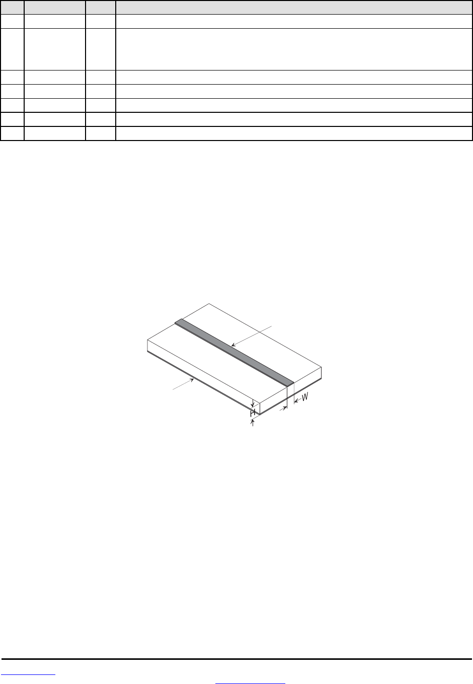
6.3 Antenna Connector
A U.FL miniature coaxial connector is provided on both DNT90 configurations for connection to the RFIO
port. A short U.FL coaxial cable can be used to connect the RFIO port directly to an antenna. In this case
the antenna should be mounted firmly to avoid stressing the U.FL coaxial cable due to antenna mounting
flexure. Alternately, a U.FL coaxial jumper cable can be used to connect the DNT90 module to a U.FL
connector on the host circuit board. The connection between the host circuit board U.FL connector and
the antenna or antenna connector on the host circuit board should be implemented as a 50 ohm
C o p p e r
G r o u n d
P l a n e
C o p p e r
S t r i p l i n e
T r a c e
F R - 4 P C B
M a t e r i a l
C i r c u i t B o a r d S t r i p l i n e T r a c e D e t a i l
F o r 5 0 o h m i m p e d a n c e W = 1 . 7 5 * H
Figure 6.3.1
Trace Separation from
50 ohm Microstrip
Length of Trace Run
Parallel to Microstrip
100 mil 125 mill
150 mil 200 mil
200 mil 290 mil
250 mil 450 mil
300 mil 650 mil
Table 6.3.2
stripline. Referring to Figure 6.3.1, the width of this stripline depends on the thickness of the circuit board
between the stripline and the groundplane. For FR-4 type circuit board materials (dielectric constant of
4.7), the width of the stripline is equal to 1.75 times the thickness of the circuit board. Note that other cir-
cuit board traces should be spaced away from the stripline to prevent signal coupling, as shown in Table
6.3.2. The stripline trace should be kept short to minimize its insertion loss.
www.RFM.com Technical support +1.678.684.2000 Page 28 of 86
©2010 by RF Monolithics, Inc. E-mail: tech_sup@rfm.com DNT90 Integration Guide - 10/25/10
6.4 Power Supply and Input Voltages
DNT90 radio modules can operate from an unregulated DC input (Pad 19) in the range of 3.3 to 5.5 V
with a maximum ripple of 5% over the temperature range of -40 to 85 oC. Applying AC, reverse DC, or a
DC voltage outside the range given above can cause damage and/or create a fire and safety hazard. Fur-
ther, care must be taken so logic inputs applied to the radio stay within the voltage range of 0 to 3.3 V.
Signals applied to the analog inputs must be in the range of 0 to ADC_EXT_REF (Pad/Pin 25). Applying a
voltage to a logic or analog input outside of its operating range can damage the DNT90 module.
6.5 ESD and Transient Protection
The DNT90C and DNT90P circuit boards are electrostatic discharge (ESD) sensitive. ESD precautions
must be observed when handling and installing these components. Installations must be protected from
electrical transients on the power supply and I/O lines. This is especially important in outdoor installations,
and/or where connections are made to sensors with long leads. Inadequate transient protection can result
in damage and/or create a fire and safety hazard.
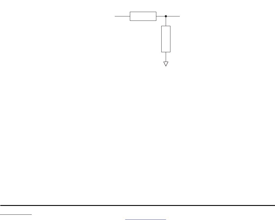
6.6 Interfacing to 5 V Logic Systems
All logic signals including the serial ports on the DNT90 are 3.3 V signals. To interface to 5 V signals, the
resistor divider network shown in Figure 3.7.1 below must be placed between the 5 V signal outputs and
the DNT90 signal inputs. The output voltage swing of the DNT90 3.3 V signals is sufficient to drive 5 V
logic inputs.
5 V
L o g i c D N T 5 0 0
2 . 2 K
4 . 3 K
Figure 6.6.1
6.7 Mounting and Enclosures
DNT90C radio modules are mounted by reflow soldering them to a host circuit board. DNT90P modules
are mounted by plugging their pins into a set of mating connectors on the host circuit board. Refer to Sec-
tion 8.3 and/or the DNT90 Data Sheet for DNT90P connector details.
DNT90 enclosures must be made of plastics or other materials with low RF attenuation to avoid compro-
mising antenna performance where antennas are internal to the enclosure. Metal enclosures are not suit-
able for use with internal antennas as they will block antenna radiation and reception. Outdoor enclosures
must be water tight, such as a NEMA 4X enclosure.
DNT90

www.RFM.com Technical support +1.678.684.2000 Page 29 of 86
©2010 by RF Monolithics, Inc. E-mail: tech_sup@rfm.com DNT90 Integration Guide - 10/25/10
6.8 Labeling and Notices
DNT90 FCC Certification - The DNT90 hardware has been certified for operation under FCC Part 15
Rules, Section 15.247. The antenna(s) used for this transmitter must be installed to provide a separation
distance of at least 20 cm from all persons and must not be co-located or operating in conjunction with
any other antenna or transmitter.
DNT90 FCC Notices and Labels - This device complies with Part 15 of the FCC rules. Operation is sub-
ject to the following two conditions: (1) this device may not cause harmful interference, and (2) this de-
vice must accept any interference received, including interference that may cause undesired operation.
A clearly visible label is required on the outside of the user’s (OEM) enclosure stating the following text:
Contains FCC ID: HSW-DNT90
Contains IC: 4492A-DNT90
RFM (Insert Model Designation DNT90C or DNT90P depending on the model used)
This device complies with Part 15 of the FCC Rules. Operation is
subject to the following two conditions: (1) This device may not cause
harmful interference, and (2) this device must accept any interference
received, including interference that may cause undesired operation.
WARNING: This device operates under Part 15 of the FCC rules. Any modification to this device, not
expressly authorized by RFM, Inc., may void the user’s authority to operate this device.
This apparatus complies with Health Canada’s Safety Code 6 / IC RSS 210.
IC RSS-210 Notice - Operation is subject to the following two conditions: (1) this device may not cause
interference, and (2) this device must accept any interference, including interference that may cause un-
desired operation of the device.
ICES-003
This digital apparatus does not exceed the Class B limits for radio noise emissions from digital apparatus
as set out in the radio interference regulations of Industry Canada.
Le present appareil numerique n’emet pas de bruits radioelectriques depassant les limites applicables
aux appareils numeriques de Classe B prescrites dans le reglement sur le brouillage radioelectrique
edicte par Industrie Canada.

www.RFM.com Technical support +1.678.684.2000 Page 30 of 86
©2010 by RF Monolithics, Inc. E-mail: tech_sup@rfm.com DNT90 Integration Guide - 10/25/10
7.0 DNT90 Protocol-formatted Messages
7.1 Protocol Formats
DNT90 modules can work in one of two serial data modes - transparent or protocol. Transparent mode
requires no data formatting, but is limited to sending serial data to a single destination. A node that needs
to send messages to more than one destination must use protocol formatting. Protocol formatting is also
required for configuration commands and replies, and sensor I/O commands, replies and events. All pro-
tocol-formatted messages have a common header as shown in Figure 7.1.1:
0 1 2 3 …
SOP Length PktType variable number of arguments …
Figure 7.1.1
The scale above is in bytes.
The Start-of-Packet (SOP) character, 0xFB, is used to mark the beginning of a protocol-formatted mes-
sage and to assure synchronization in the event of a glitch on the serial port at startup.
The Length byte is defined as the length of the remainder of the message following the length byte itself,
or the length of the entire message - 2.
The Packet Type (PktType) byte specifies the type of message. It is a bitfield-oriented specifier, decoded
as follows:
Bits 7..5 Reserved for future use
Bit 4 Reply - this bit is set to indicate a message is a reply
Bits 3..0 Type - these bits indicate the message type
As indicated, the lower four bits (3..0) specify a message type. Bit 4 is a modifier indicating that the mes-
sage is a command or a reply. A reply message has the original command type in bits 3..0, with Bit 4 set
to one.
Arguments vary in size and number depending on the type of message and whether it is a message sent
from the host, or is a reply or event message from the radio. See Section 7.3 below.
7.2 Message Types
Messages generated on the serial interface by the user are referred to as host messages. Messages
generated on the serial interface by the radio are referred to as reply or event messages. Host messages
carry commands. For most commands, there is a corresponds reply message. For example, when the
host sends a TxData command message, the radio will return a TxDataReply message to indicate the
status of the transmission - whether it succeeded or failed. To assist in interpreting the command-reply
data flow, the direction is indicated by the high nibble in the message type. For example, an EnterProto-
colMode command from the host is a message type 0x00, and the EnterProtocolModeReply from the ra-
dio is a message type 0x10.
Event messages from a DNT90, such as received data or status announcements make up a third catego-
ry of messages. Event messages, including RxData, RxEvent and Announce packets are indicated by
0x20 in the high nibble of the type byte. If multiple arguments are to be provided, they are to be concate-
nated in the order shown in Section 7.3 below. Little-Endian byte order is used for all multi-byte

www.RFM.com Technical support +1.678.684.2000 Page 31 of 86
©2010 by RF Monolithics, Inc. E-mail: tech_sup@rfm.com DNT90 Integration Guide - 10/25/10
arguments except text strings. Little-Endian byte order places the lowest order byte in the left-most byte
of the argument and the highest order byte in the right-most byte of the argument.
7.3 Message Format Details
Table 7.3.1 below summarizes the DNT90 protocol-formatted messages:
Com-
mand Reply Event Type Direction Min Slot Size
0x00 - -
EnterProtocolMode from Host N/A
- 0x10 -
EnterProtocolModeReply from Radio N/A
0x01 - -
ExitProtocolMode from Host N/A
0x02 - -
DeviceReset from Host N/A
- 0x12 -
DeviceResetReply from Radio N/A
0x03 - -
GetRegister from Host N/A
- 0x13 -
GetRegisterReply from Radio N/A
0x04 - -
SetRegister from Host N/A
- 0x14 -
SetRegisterReply from Radio N/A
0x05 - -
TxData from Host length value -0x03
- 0x15 -
TxDataReply from Radio 0x01
0x06 - -
GetRemoteRegister from Host 0x03
- 0x16 -
GetRemoteRegisterReply from Radio 0x14
0x07 - -
SetRemoteRegister from Host 0x13
- 0x17 -
SetRemoteRegisterReply from Radio 0x04
- - 0x26
RxData from Radio length value -0x03
- - 0x27
Announce/Error from Radio 0x07
- - 0x28
RxEvent from Radio 0x0D
Table 7.3.1
EnterProtocolMode command and reply format details are presented in Tables 7.3.2 and 7.3.3:
Enter Protocol Mode Command
Byte Offset Field Description
0x00 Start-of-Packet 0xFB = Indicates start of protocol formatted message
0x01 Length 0x07 = Number of bytes in message following this byte
0x02 Packet Type 0x00 = EnterProtocolMode
0x03 - 0x08 Payload String = “DNTCFG”
Table 7.3.2
Enter Protocol Mode Reply
Byte Offset Field Description
0x00 Start-of-Packet 0xFB = Indicates start of protocol formatted message
0x01 Length 0x01 = Number of bytes in message following this byte
0x02 Packet Type 0x10 = EnterProtocolModeReply
Table 7.3.3

www.RFM.com Technical support +1.678.684.2000 Page 32 of 86
©2010 by RF Monolithics, Inc. E-mail: tech_sup@rfm.com DNT90 Integration Guide - 10/25/10
ExitProtocolMode command format details are shown in Table 7.3.4:
Exit Protocol Mode Command
Byte Offset Field Description
0x00 Start-of-Packet 0xFB = Indicates start of protocol formatted message
0x01 Length 0x01 = Number of bytes in message following this byte
0x02 Packet Type 0x01 = ExitProtocolMode
Table 7.3.4
DeviceReset command and reply format details are shown in Tables 7.3.5 and 7.3.6:
Device Reset Command
Byte Offset Field Description
0x00 Start-of-Packet 0xFB = Indicates start of protocol formatted message
0x01 Length 0x02 = Number of bytes in message following this byte
0x02 Packet Type 0x02 = DeviceReset
0x03 Reset Type
0x00 = Normal Device Reset
0x01 = Reset to Serial Bootloader
0x02 = Reset to Over-the-Air Bootloader
Table 7.3.5
Device Reset Reply
Byte Offset Field Description
0x00 Start-Of-Packet 0xFB = Indicates start of protocol formatted message
0x01 Length 0x01 = Number of bytes in message following this byte
0x02 Packet Type 0x12 = DeviceResetReply
Table 7.3.6
GetRegister command and reply format details are shown in Tables 7.3.7 and 7.3.8:
Get Register Command
Byte Offset Field Description
0x00 Start-of-Packet 0xFB = Indicates start of protocol formatted message
0x01 Length 0x04 = Number of bytes in message following this byte
0x02 Packet Type 0x03 = GetRegister
0x03 Register Offset Register offset in its bank
0x04 Register Bank Register bank number
0x05 Register Size Register size in bytes
Table 7.3.7

www.RFM.com Technical support +1.678.684.2000 Page 33 of 86
©2010 by RF Monolithics, Inc. E-mail: tech_sup@rfm.com DNT90 Integration Guide - 10/25/10
Get Register Reply
Byte Offset Field Description
0x00 Start-of-Packet 0xFB = Indicates start of protocol formatted message
0x01 Length 0x05 to 0x20 = Number of bytes in message following this byte
0x02 Packet Type 0x03 = Get register reply
0x03 Register Offset Register offset in its bank
0x04 Register Bank Register bank number
0x05 Register Size Register size in bytes
0x0 6 - 0x15 Register Value Register value, all bytes in the register
Note: an Error message will be returned instead of a Get Register Reply in case of a format error.
Table 7.3.8
SetRegister command and reply format details are shown in Tables 7.3.9 and 7.3.10:
Set Register Command
Byte Offset Field Description
0x00 Start-of-Packet 0xFB = Indicates start of protocol formatted message
0x01 Length 0x05 to 0x20 = Number of bytes in message following this byte
0x02 Packet Type 0x04 = Set register command
0x03 Register Offset Register offset in its bank
0x04 Register Bank Register bank number
0x05 Register Size Register size in bytes
0x06 - 0x15 Register Value Register value, all bytes in the register
Table 7.3.9
Set Register Reply
Byte Offset Field Description
0x00 Start-of-Packet 0xFB = Indicates start of protocol formatted message
0x01 Length 0x01 = Number of bytes in message following this byte
0x02 Packet Type 0x14 = Set register reply
Note: an Error message will be returned instead of a Set Register Reply in case of a format error.
Table 7.3.10
TXData command and reply format details are shown in Tables 7.3.11 and 7.3.12:
TX Data Command
Byte Offset Field Description
0x00 Start-of-Packet 0xFB = Indicates start of protocol formatted message
0x01 Length 0x07 = Number of bytes in message following this byte
0x02 Packet Type 0x05 = TX data command
0x03 - 0x05 Destination MAC Address Destination MAC address, in Little Endian byte order
0x06 - 0x72 Tx Data Up to 109 bytes of data to Base, or 105 bytes from Base
Table 7.3.11

www.RFM.com Technical support +1.678.684.2000 Page 34 of 86
©2010 by RF Monolithics, Inc. E-mail: tech_sup@rfm.com DNT90 Integration Guide - 10/25/10
TX Data Reply
Byte Offset Field Description
0x00 Start-of-Packet 0xFB = Indicates start of protocol formatted message
0x01 Length 0x07 = Number of bytes in message following this byte
0x02 Packet Type 0x15 = TxDataReply
0x03 - 0x05 Destination MAC Address Destination MAC address, in Little Endian byte order
0x06 Status
0x00 = ACK received from destination
0x01 = no ACK received from destination (NAK)
0x02 = “Device Not Linked” error
0x07 RSSI Packet RX power in dBm (-128 to 127) or 0x7F if invalid
Table 7.3.12
GetRemoteRegister command and reply details are shown it Tables 7.3.13 and 7.3.14:
Get Remote Register Command
Byte Offset Field Description
0x00 Start-of-Packet 0xFB = Indicates start of protocol formatted message
0x01 Length 0x07 = Number of bytes in message following this byte
0x02 Packet Type 0x06 = Get Remote Register Command
0x03 - 0x05 Destination MAC Address Destination MAC address, in Little Endian byte order
0x06 Register Offset Register offset in its bank
0x07 Register Bank Register bank number
0x08 Register Size Register size in bytes
Table 7.3.13
Get Remote Register Reply
Byte Offset Field Description
0x00 Start-of-Packet 0xFB = Indicates start of protocol formatted message
0x01 Length 0x0A to 0x25 = Number of bytes in message following this byte
0x02 Packet Type 0x16 = Get Remote Register Reply
0x03 Status Error status (0x00 = No Error, 0xE1 = Invalid Argument)
0x04 - 0x06 Originator MAC Address Originator’s MAC address, in Little Endian byte order
0x07 RSSI Packet RX power in dBm (-128 to 127)
0x08 Register Offset* Register offset in its bank
0x09 Register Bank* Register bank number
0x0A Register Size* Register size in bytes
0x0B - 0x1A Register Value* Register value, all bytes in the register
*Bytes eight through the end of the message will not be returned in case of an error
Table 7.3.14

www.RFM.com Technical support +1.678.684.2000 Page 35 of 86
©2010 by RF Monolithics, Inc. E-mail: tech_sup@rfm.com DNT90 Integration Guide - 10/25/10
SetRemoteRegister command and reply format details are shown in Tables 7.3.15 and 7.3.16:
Set Remote Register Command
Byte Offset Field Description
0x00 Start-of-Packet 0xFB = Indicates start of protocol formatted message
0x01 Length Number of bytes in message following this byte
0x02 Packet Type 0x07 = Set remote register command
0x03 - 0x05 Destination MAC Address Destination MAC address, in Little Endian byte order
0x06 Register Offset Register offset in its bank
0x07 Register Bank Register bank number
0x08 Register Size Register size in bytes
0x09 - 0x18 Register Value Register contents
Table 7.3.15
Set Remote Register Reply
Byte Offset Field Description
0x00 Start-of-Packet 0xFB = Indicates start of protocol formatted message
0x01 Length 0x06 = Number of bytes in message following this byte
0x02 Packet Type 0x17 = Set remote register reply
0x03 Status Error status: 0x00 = no error, 0xE1 = invalid argument
0x04 - 0x06 Originator MAC Address Originator’s MAC address, in Little Endian byte order
0x07 RSSI Packet RX power in dBm, -128 to 127
Table 7.3.16
RxData event packet format details are shown in Figure Table 7.3.17:
RX Data Packet
Byte Offset Field Description
0x00 Start-of-Packet 0xFB = Indicates start of protocol formatted message
0x01 Length 0x00 to 0x6D = Number of bytes in message following this byte
0x02 Packet Type 0x26 = RxData event message
0x03 - 0x05 Originator MAC Address Originator’s MAC address, in Little Endian byte order
0x06 RSSI Packet RX power in dBm (-128 to 127)
0x07 - 0x73 Rx Data Up to 105 bytes of data from Base, up to 109 bytes from Router or Remote
Table 7.3.17

www.RFM.com Technical support +1.678.684.2000 Page 36 of 86
©2010 by RF Monolithics, Inc. E-mail: tech_sup@rfm.com DNT90 Integration Guide - 10/25/10
Announce/Error message format details are shown in Tables 7.3.18 through 7.3.21:
Startup Announcement or Error Code
Byte Offset Field Description
0x00 Start-of-Packet 0xFB = Indicates start of protocol formatted message
0x01 Length 0x02 = Number of bytes in message following this byte
0x02 Packet Type 0x27 = Indicates this is an Announce/Error message
0x03 Announce Status
0xA0 = Startup initialization complete
0xE1 = Invalid argument
0xE4 = Register read only error
0xEC = Brownout reset
0xED = Watchdog reset
0xEE = Hardware Error (Crystal or Radio Error)
Table 7.3.18
Join Announcement
Byte Offset Field Description
0x00 Start-of-Packet 0xFB = Indicates start of protocol formatted message
0x01 Length 0x06 = Number of bytes in message following this byte
0x02 Packet Type 0x27 = Indicates this is an Announce/Error message
0x03 Announce Status 0xA3 = Joined network
0x04 Network ID ID of network that was joined
0x05 - 0x07 Parent MAC Address MAC address of parent, in Little Endian byte order
Table 7.3.19
Exit Announcement
Byte Offset Field Description
0x00 Start-of-Packet 0xFB = Indicates start of protocol formatted message
0x01 Length 0x03 = Number of bytes in message following this byte
0x02 Packet Type 0x27 = Indicates this is an Announce/Error message
0x03 Announce Status 0xA4 = Exited network
0x04 Network ID ID of network that was exited
Table 7.3.20
Heartbeat Announcement
Byte Offset Field Description
0x00 Start-of-Packet 0xFB = Indicates start of protocol formatted message
0x01 Length 0x0C = number of bytes in message following this byte
0x02 Packet Type 0x27 = Indicates this is an Announce/Error message
0x03 Announce Status 0xA8 = Heartbeat message
0x04 - 0x06 Device MAC Address MAC address of originator, in Little Endian byte order
0x07 - 0x09 Parent MAC Address MAC address of parent, in Little Endian byte order
0x0A Parent Network ID Network ID of device’s parent
0x0B Base Mode Network ID Network ID if device is a router, otherwise 0xFF
0x0C Beacon RX Power Average beacon RX power in dBm, uses 0.0625 “alpha” filter
0x0D Parent RX Power RX power of packet as received by device’s parent in dBm
Table 7.3.21

www.RFM.com Technical support +1.678.684.2000 Page 37 of 86
©2010 by RF Monolithics, Inc. E-mail: tech_sup@rfm.com DNT90 Integration Guide - 10/25/10
RxEvent message format details are shown in Table 7.3.22:
RX Event Packet
Byte Offset Field Description
0x00 Start-of-Packet 0xFB = Indicates start of protocol formatted message
0x01 Length 0x12 = number of bytes in message following this byte
0x02 Packet Type 0x28 = RxEvent
0x03 - 0x05 Originator MAC Address Originator’s MAC address, in Little Endian byte order
0x06 RSSI Packet RX power in dBm (-128 to 127)
0x07 GPIO Readings Bit Field (GPIO0..GPIO5) indicating GPIO readings
0x08 - 0x09 ADC0 Reading ADC0 Reading, 0x0000 - 0x0FFF, in Little Endian byte order
0x0A - 0x0B ADC1 Reading ADC1 Reading, 0x0000 - 0x0FFF, in Little Endian byte order
0x0C - 0x0D ADC2 Reading ADC2 Reading, 0x0000 - 0x0FFF, in Little Endian byte order
0x0E - 0x0F Event Flags Bit Field Indicating which events have occurred:
Bit 0: GPIO0 Triggered
Bit 1: GPIO1 Triggered
Bit 2: GPIO2 Triggered
Bit 3: GPIO3 Triggered
Bit 4: Periodic Report Interval
Bit 5: ADC0 Threshold Triggered
Bit 6: ADC1 Threshold Triggered
Bit 7: ADC2 Threshold Triggered
Bits 8-15: Unused (0)
0x10-0x00 DAC0 Setting DAC0 setting, 0x0000 - 0x0FFF, in Little Endian byte order
0x12 - 0x13 DAC1 Setting DAC1 setting, 0x0000 - 0x0FFF, in Little Endian byte order
Table 7.3.22

www.RFM.com Technical support +1.678.684.2000 Page 38 of 86
©2010 by RF Monolithics, Inc. E-mail: tech_sup@rfm.com DNT90 Integration Guide - 10/25/10
7.4 Configuration Parameter Registers
The configuration parameters in a DNT90 module are stored in a set of variable length registers. Most
registers are read-write, with a few read-only or write-only. Changes made to the register settings are
temporary until a MemorySave command is executed. Resetting or power-cycling the module will clear
any changes that have not been saved to permanent memory using the MemorySave command. DNT90
modules can be configured to start in protocol mode at power-up, in which case the EnterProtocolMode
command is not required.
7.4.1 Bank 0 - Transceiver Setup
Bank Location Name R/W Size Range Default
0x00 0x00 DeviceMode R/W 0x01 0..2 0
0x00 0x01 HopDuration R/W 0x01 16..200 40 (20 ms)
0x00 0x02 ParentNwkID R/W 0x01 0..63, 255 0xFF
0x00 0x03 SecurityKey R/W 0x10 0..2^128-1 0
0x00 0x13 SleepModeEn R/W 0x01 0..1 0
0x00 0x14 WakeResponseTime R/W 0x02 0..30000 500 (500 ms)
0x00 0x15 WakeLinkTimeout R/W 0x02 0..30000 5000 (5 s)
0x00 0x16 TxPower R/W 0x01 0..1 0
0x00 0x17 UserTag R/W 0x10 “DNT90”
0x00 0x27 RmtTransDestAddr R/W 0x03 0x000000 (Base)
0x00 0x2A Store&ForwardEn R/W 0x01 0..1 0 (Off)
0x00 0x2B BaseModeNetID R/W 0x01 1..63255 0xFF
0x00 0x2C HeartbeatIntrvl R/W 0x02 0..65535 20 (seconds)
0x00 0x2E SystemID R/W 0x01 0..255 0
0x00 0x2F AckEnable R/W 0x01 0..1 0
0x00 0x32 AltParentNwkID R/W 0x01 0..63, 255 0xFF (disabled)
Table 7.4.1.1
DeviceMode - this parameter selects the operating mode for the radio:
0x00 = remote (default)
0x01 = base
0x02 = router (store and forward system)
Note that changing this setting does not take effect immediately. It must be followed by a MemorySave
command and then a hardware reset.
HopDuration - this parameter sets the duration of the hop frame. The duration is set as an 8-bit value,
0.5 ms/count. The valid hop duration range is from 8 to 100 ms. Changing the hop duration must be fol-
lowed by a MemorySave command to allow the change to persist through a reset or power cycle. A Hop-
Duration change takes effect immediately. Remotes will re-link following a HopDuration parameter
change.
ParentNwkID - this parameter specifies the parent (BaseModeNetID) that a child radio is allowed to join.
The valid range of this parameter is 0x00 to 0x3F, plus 0xFF. Setting the ParentNwkID to 0xFF to allow
connection to any parent. This parameter is applicable only to remotes and routers. Also see the discus-
sion of AltParentNwkID below.

www.RFM.com Technical support +1.678.684.2000 Page 39 of 86
©2010 by RF Monolithics, Inc. E-mail: tech_sup@rfm.com DNT90 Integration Guide - 10/25/10
Security Key - this 16-byte parameter sets the 128-bit AES encryption key. To protect the key, it is a write-
only parameter for the user. It always reads back as 0x2A.
SleepModeEn - this parameter enables/disables sleep mode. Sleep mode is used in conjunction with the
automatic I/O reporting feature to wake up a remote on specific triggers. Sleep mode can only be used
with remotes.
WakeResponseTime - this parameter set how long sleep is deferred in a DNT90 remote configured for
sleep mode after:
link acquisition
receiving an ACK from the device’s parent
receiving a packet that requires processing by the device
after receiving a protocol packet from the device’s local host.
WakeLinkTimeout - this parameter sets the maximum length of time that a remote in sleep mode will
spend trying to acquire a link to its parent before going back to sleep, from a minimum of 1 ms to 30 s
in 1 ms steps. If this value is set to 0, the remote will stay awake and continue trying to link to its base
indefinitely.
TxPower - this parameter sets the transmit power level:
0x00 = +16 dBm or 40 mW
0x01 = +22 dBm or 158 mW
UserTag - this parameter is a user definable field intended for use as a location description or other iden-
tifying tag such as a “friendly name”.
RmtTransDestAddr - this parameter holds the default destination for transparent mode data packets and
event packets. This parameter defaults to the base station’s address (0x000000) except on a base sta-
tion, where at startup it will be changed to the broadcast address (0xFFFFFF) if the firmware detects that
it is set to 0x000000.
Store&ForwardEn - setting this parameter to 0x01 enables store-and-forward system operation. Store-
and-forward operation is disabled by default.
BaseModeNetID - applicable to the base and routers only, this parameter specifies the network ID of a
device’s own network when acting as parent. A child is allowed to join a network when its ParentNwkID
parameter matches a parent’s BaseModeNetID. The valid range of this parameter is 0x00 to 0x3F. A val-
ue greater than 0x3F is invalid and will be forced to 0x00 on a base. A router with an invalid Base-
ModeNetID will be forced to operate as a remote.
HeartbeatInterval - When set to 0, all heartbeats are disabled, including the initial heartbeat issued after
link acquisition. When set to 0xFFFF, periodic heartbeats are disabled but the initial linkup heartbeat is
enabled. If sleep mode is enabled, heartbeats will be generated only if either periodic or ADC sample wa-
keups are scheduled, since heartbeats can be generated only on wakeup events. Also, the DNT90’s real
time clock is disabled if neither periodic nor ADC wakeups are scheduled, and heartbeat intervals there-
fore cannot be tracked. The heartbeat interval is scaled 1 second/count.
SystemID - this parameter holds the ID for a DTN90 system. DNT90 systems that may physically overlap
must have different system IDs.

www.RFM.com Technical support +1.678.684.2000 Page 40 of 86
©2010 by RF Monolithics, Inc. E-mail: tech_sup@rfm.com DNT90 Integration Guide - 10/25/10
AckEnable - when this parameter is set to 1, the originator will indicate in its transmitted packet that an
ACK is expected from the packet’s remote destination. Setting this parameter to 0x00 (default) reduces
network congestion, but no TXDataReply will be sent from the destination to confirm reception.
AltParentNwkID - this parameter specifies an alternate parent (BaseModeNetID) that a child radio is
allowed to join. This parameter is used to provide more robust message routing when setting the
ParentNwkID to its 0xFF wildcard value is not appropriate. The valid range of this parameter is 0x00 to
0x3F, plus 0xFF. Rather than specifying wildcard operation, setting the AltParentNwkID to 0xFF disables
the selection of an alternate parent. This parameter is applicable only to remotes and routers.
7.4.2 Bank 1 - System Settings
Bank 1 holds configuration parameters to be input to the base only. The base passes these parameters to
the routers and remotes as needed. The exception is InitFrequencyBand …
Bank Location Name R/W Size Range Default
0x01 0x00 InitFrequencyBand R/W 0x01 0..2, 255 0 (US)
0x01 0x01 NumSlots R/W 0x01 1..8 3
0x01 0x02 BaseSlotSize R/W 0x01 6..105 50
0x01 0x03 SlotLease R/W 0x01 1..255 4 (hops)
0x01 0x04 ArqMode R/W 0x01 0..1 1 (Repeat Broadcasts)
0x01 0x05 ArqAttemptLimit R/W 0x01 1..63 4
0x01 0x06 LinkDropThreshold R/W 0x01 1..255 10 (hops)
0x01 0x07 P2PReplyTimeout R/W 0x01 0..255 100 (hops)
0x01 0x08 RegistryTimeout R/W 0x01 0..255 50 (hops)
Table 7.4.2.1
InitFrequencyBand - this parameter sets the range of frequencies and channel spacing over which the
DNT90 system will operate. Three bands are available:
0x00 Band 0: 902.76 to 927.24 MHz, 52 channels, 480 kHz spacing
0x01 Band 1: 902.76 to 926.76 MHz, 26 channels, 960 kHz spacing
0x02 Band 2: 915.72 to 927.74 MHz, 25 channels, 480 kHz spacing
Bands 0, 1 and 2 can be used in North and South America (902 to 928 MHz band), with Band 2 usable in
Australia, New Zealand and certain other international locations (915 to 928 MHz band).
NumSlots - this parameter sets the number of slots for child router/remote transmissions on each hop.
BaseSlotSize - this parameter set the maximum number of payload bytes that the base can send on a
single hop. The default value is 40 bytes.
SlotLease - this parameter set the number of hops a parent radio will reserve a slot for a child after re-
ceiving a message from that child. Small values such as 0x02 are suited to short data bursts, and larger
values are generally a better choice when devices send a stream of data across consecutive hops. The
minimum value is 1, assuring that a child can receive an ACK on the next hop after it transmits.
BroadcastMode - setting this parameter to 0x01 enables broadcast automatic repeat mode.

www.RFM.com Technical support +1.678.684.2000 Page 41 of 86
©2010 by RF Monolithics, Inc. E-mail: tech_sup@rfm.com DNT90 Integration Guide - 10/25/10
ArqAttemptLimit - this sets the maximum number of attempts that will be made to send a message on the
RF link. Setting this parameter to the maximum value of 63 is a flag value indicating that there should be
no limit to the number of attempts to send each packet (infinite number of attempts). This mode is in-
tended for point-to-point networks in serial data cable replacement applications where absolutely no
packets can be lost. Note - if this mode is used in a multipoint network, one remote that has lost link will
shut down the entire network if the base is trying to send it data.
LinkDropThreshold - this is the number of consecutive beacons missed by a remote that causes the re-
mote to restart a link acquisition search. Please contact RFM technical support before making changes to
the parameter.
P2PReplyTimeout - this parameter sets the reply timeout for peer-to-peer packets sent from one node to
another. Because each leg of the journey from one node to another and back may take multiple transmit
attempts, the length of time to confirm receipt and issue a TxDataReply is subject to more variation than a
transmission directly between a base and a remote. The P2PReplyTimeout parameter specifies the max-
imum number of hops or hop pairs that a remote will wait for a reply from its recipient. If a reply returns
sooner than the timeout, the remote will send a TxDataReply indicating success (ACK) to its host as soon
as it is received, and cancels the timeout. If a reply does not come back before the timeout expires, the
remote will send a TxDataReply to its host indicating failure (NAK). If a reply should come back after the
timeout expires the remote will ignore it, as a TxDataReply has already been sent. The units of this para-
meter are in hops for point-to-point and point-to-multipoint operation and in hop pairs for store-and-
forward operation.
RegistryTimeout - this parameter sets the number of hops without contact from a child device for which a
parent device will preserve the Transaction ID (TID) history for that child. After this timeout, the TID histo-
ry is reset.
7.4.3 Bank 2 - Status Parameters
Bank Location Name R/W Size Range Default
0x02 0x00 MacAddress R 0x03 0..0xFFFFFF Fixed value
0x02 0x03 CurrNwkID R 0x01 0..63, 255 As set
0x02 0x04 CurrFreqBand R 0x01 0..2, 255 As set
0x02 0x05 LinkStatus R 0x01 0..5 Current status
0x02 0x06 RemoteSlotSize R 0x01 0..109 As set
0x02 0x07 SlotNumber R 0x01 0..7 As set
0x02 0x08 HardwareVersion R 0x01 0x41..0x5A 0x41 = Rev “A”
0x02 0x09 FirmwareVersion R 0x01 0x00..0xFF Current FW load
0x02 0x0A FirmwareBuildNum R 0x02 0..65535 Current FW load
0x02 0x0C FirmwareBuildDate R 0x03 BCD (“YYMMDD”) Current FW load
0x02 0x0F FirmwareBuildTime R 0x03 BCD (“HHMMSS”) Current FW load
0x02 0x12 RssiIdle R 0x01 -128..127 As set
0x02 0x13 RssiLast R 0x01 -128..127 As set
0x02 0x14 AvgBeaconPower R 0x01 -128..127 As set
0x02 0x15 ParentMacAddress R 0x03 0..0xFFFFFF As set
Table 7.4.3.1
MacAddress - this parameter holds the radio's unique 24-bit MAC address.

www.RFM.com Technical support +1.678.684.2000 Page 42 of 86
©2010 by RF Monolithics, Inc. E-mail: tech_sup@rfm.com DNT90 Integration Guide - 10/25/10
CurrNwkID - this parameter holds the ID of the network the radio is currently assigned to or connected to.
A value of 0xFF means the radio is scanning for a network but has not yet joined one.
CurrFreqBand - this parameter holds the frequency band of the network that the radio is currently as-
signed to or connected to. A value of 0xFF means the radio is scanning for a network at power up but has
not yet joined one.
LinkStatus - this parameter holds the link status of a router or remote:
0x00 = idle
0x01 = lost link
0x02 = acquiring link
0x03 = collecting parameters from the base
0x04 = registering
0x05 = registered
RemoteSlotSize - this parameter holds the current remote slot size, defined as the maximum number of
message bytes a remote can send on a single hop.
SlotNumber - this parameter holds the current slot number assigned to a router or remote.
HarwareVersion - this parameter holds an identifier indicating the hardware revision (ASCII character). A
value of 0x43 is defined for the DNT90 Rev C hardware.
FirmwareVersion - this parameter holds the firmware version of the radio in 2-digit BCD format.
FirmwareBuildNum - this parameter holds the firmware build number, in binary format.
FirmwareBuildDate - this parameter holds the date of firmware build in MM/DD/YY format.
FirmwareBuildTime - this parameter holds the time of the firmware build in HH:MM:SS format.
RssiIdle - this parameter holds the last RSSI measurement made during a time when the RF channel was
idle. This parameter is useful for detecting interferers.
RssiLast - this parameter holds the last RSSI measurement made during the receipt of an RF packet with
a valid CRC. This parameter is useful for network commissioning and diagnostic purposes.
AvgBeaconPower - Alpha-filtered beacon power received from a device’s parent where alpha = 0.0625.
ParentMacAddress - this parameter holds the MAC address of a DNT90’s parent.

www.RFM.com Technical support +1.678.684.2000 Page 43 of 86
©2010 by RF Monolithics, Inc. E-mail: tech_sup@rfm.com DNT90 Integration Guide - 10/25/10
7.4.4 Bank 3 - Serial and SPI Settings
Bank Location Name R/W Size Range Default
0x03 0x00 SerialRate R/W 0x01 0..10 3 (9600 baud)
0x03 0x01 SerialParams R/W 0x01 0..7 0 (8-N-1)
0x03 0x02 SpiMode R/W 0x01 0..2 0 (SPI Disabled)
0x03 0x03 SpiRateSel R/W 0x01 0..2 0 (125 kHz)
0x03 0x04 SpiOptions R/W 0x01 0..7 0
0x03 0x05 SpiMasterCmdLen R/W 0x01 0..16 0
0x03 0x06 SpiMasterCmdStr R/W 0x10 ASCII All 0x00 bytes
Table 7.4.4.1
SerialRate - this parameter sets the serial data rate as shown below:
Setting Serial rate
0x00 1.2 kbps
0x01 2.4 kbps
0x02 4.8 kbps
0x03 9.6 kbps
0x04 14.4 kbps
0x05 19.2 kbps
0x06 28.8 kbps
0x07 38.4 kbps
0x08 57.6 kbps
0x09 115.2 kbps
0x0A 230.4 kbps
SerialParams - this parameter sets the serial mode options for parity and stop bits:
Setting Mode
0x00 No parity, 8 data bits, 1 stop bit (default)
0x01 No parity, 8 data bits, 2 stop bits
0x02 Reserved
0x03 Reserved
0x04 Even parity, 8 data bits, 1 stop bit
0x05 Even parity, 8 data bits, 2 stop bits
0x06 Odd parity, 8 data bits, 1 stop bit
0x07 Odd parity, 8 data bits, 2 stop bits
Note that 8-bit data with no parity is capable of carrying 7-bit data with parity for compatibility without loss
of generality for legacy applications that may require it.
SpiMode - this parameter sets the SPI operating mode:
Setting Mode
0x00 SPI disabled - serial UART mode (default)
0x01 SPI Slave mode
0x02 SPI Master mode
SpiRateSel - this parameter sets the SPI master mode clock rate:
Setting Mode
0x00 125 kbps
0x01 250 kbps
0x02 500 kbps
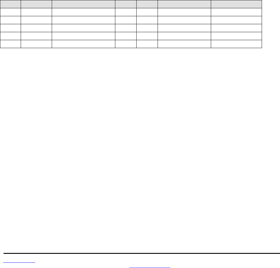
www.RFM.com Technical support +1.678.684.2000 Page 44 of 86
©2010 by RF Monolithics, Inc. E-mail: tech_sup@rfm.com DNT90 Integration Guide - 10/25/10
SpiOptions - this parameter allows the SPI to be configured with the following options:
Setting Option
0x00 Leading edge rising, sample leading edge, MSBs sent first
0x01 Leading edge rising, sample falling edge, MSBs sent first
0x02 Leading edge falling, sample leading edge, MSBs sent first
0x03 Leading edge falling, sample falling edge, MSBs sent first
0x04 Leading edge rising, sample leading edge, LSBs sent first
0x05 Leading edge rising, sample falling edge, LSBs sent first
0x06 Leading edge falling, sample leading edge, LSBs sent first
0x07 Leading edge falling, sample falling edge, LSBs sent first
SpiMasterCmdLen - this parameter sets the length for the SPI master command string that will be used to
interrogate the slave peripheral, when SPI master mode is selected with periodic I/O reporting enabled.
SpiMasterCmdStr - this parameter holds the SPI master command string that is used to interrogate the
slave peripheral when SPI master mode is selected and periodic I/O reporting is enabled.
7.4.5 Bank 4 - Host Protocol Settings
Bank Location Name R/W Size Range Default
0x04 0x00 ProtocolMode R/W 0x01 0..1 0 (Transparent)
0x04 0x01 TxTimeout R/W 0x01 0..255 0 (No timeout)
0x04 0x02 MinPacketLength R/W 0x01 0..255 1 (byte)
0x04 0x03 TransPtToPtMode R/W 0x01 0..1 0 (Multipoint)
0x04 0x04 MsgPerHop R/W 0x01 1..8 8
Table 7.4.5.1
ProtocolMode - this parameter selects the host protocol mode. The default is 0x00, which is transparent
mode, meaning the radio conveys whatever characters that are sent to it transparently, without requiring
the host to understand or conform to the DNT90's built-in protocol. This setting is recommended for point-
to-point applications for legacy applications such as wire replacements where another serial protocol may
already exist. Setting this parameter to 0x01 enables the DNT90 protocol formatting. It is not necessary to
define the same protocol mode for all radios in a network. For example, it is frequently useful to configure
all the remotes for transparent mode and the base for protocol mode. Note that it is possible for the host
to switch the radio from transparent mode to protocol mode and back as required by transmitting an
EnterProtocolMode command.
TxTimeout - this parameter is the transmit timeout used for determining message boundaries in transpa-
rent data mode. Parameter units are in milliseconds. A message boundary is determined whenever a gap
between consecutive characters is equal to or greater than the TxTimeout value, or the number of bytes
reaches the MinPacketLength. Either condition will trigger a transmission. The default TxTimeout value
is 0 ms.
MinPacketLength - sets the minimum message length used for determining packet boundaries in transpa-
rent data mode. The default is one byte. A transmission is triggered when either the number of bytes
reaches MinPacketLength or a gap is detected between consecutive characters greater than TxTimeout.

www.RFM.com Technical support +1.678.684.2000 Page 45 of 86
©2010 by RF Monolithics, Inc. E-mail: tech_sup@rfm.com DNT90 Integration Guide - 10/25/10
TransPtToPtMode - when this parameter is set to 0x00, the destination address of transparent mode
packets will be the configured RemoteDestAddr. When set to 0x01, the destination address of transparent
mode packets will be the originator of the most recent RX packet processed.
MaxDataPackets - this parameter sets the maximum number of messages a DNT90 can send in each
hop frame. The parameter range is 1 to 8 messages.
7.4.6 Bank 5 - I/O Parameters
Bank Location Name R/W Size Range In Bits Default
0x05 0x00 All-IO R/W 0x0D 104 N/A
0x05 0x0D Gpio0 R/W 0x01 1 0
0x05 0x0E Gpio1 R/W 0x01 1 0
0x05 0x0F Gpio2 R/W 0x01 1 0
0x05 0x10 Gpio3 R/W 0x01 1 0
0x05 0x11 Gpio4 R/W 0x01 1 0
0x05 0x12 Gpio5 R/W 0x01 1 0
0x05 0x13 Adc0 R 0x02 12 N/A
0x05 0x15 Adc1 R 0x02 12 N/A
0x05 0x17 Adc2 R 0x02 12 N/A
0x05 0x19 EventFlags R 0x02 16 N/A
0x05 0x1B Dac0 R/W 0x02 12 0
0x05 0x1D Dac1 R/W 0x02 12 0
Table 7.4.6.1
All-IO - this 13-byte parameter packs all the following parameters into a single value. Note that the infor-
mation in parameters GPIO0 through GPIO5 are compressed into a single byte to save space in the All-
IO parameter.
Gpio0 through Gpio5 - if a pin is configured as an output, writing to its corresponding parameter to sets
the pin’s logic state. If a pin is configured as an input, writing to its corresponding parameter enables or
disables the pin’s internal pull-up. Reading these registers returns the current level detected on the cor-
responding pins.
Adc0 through Adc2 - read-only parameters that return the current 12-bit reading for the selected ADC
channel (Little-Endian byte order). See the discussion of the AdcSampleIntvl parameter below.
EventFlags - used with the automatic I/O reporting feature, this read-only parameter indicates which I/O
events have been triggered since the last report:
bits 15..8 Reserved
bit 7 ADC2 high/low threshold excursion
bit 6 ADC1 high/low threshold excursion
bit 5 ADC0 high/low threshold excursion
bit 4 Periodic timer report
bit 2 GPIO2 edge transition
bit 1 GPIO1 edge transition
bit 0 GPIO0 edge transition
Dac0 through Dac1 - sets the DAC outputs. The DAC output voltages are filtered through an integrated
low-pass filter to provides an effective DAC resolution of 12 bits. The range of this parameter is 0x0000 to
0x0FFF.

www.RFM.com Technical support +1.678.684.2000 Page 46 of 86
©2010 by RF Monolithics, Inc. E-mail: tech_sup@rfm.com DNT90 Integration Guide - 10/25/10
7.4.7 Bank 6 - I/O Settings
Bank Location Name R/W Size Range In Bits Default
0x06 0x00 GpioDir R/W 0x01 6 0x00 (All inputs)
0x06 0x01 GpioInit R/W 0x01 6 0x00 (All zero)
0x06 0x02 GpioAlt R/W 0x01 6 0xC0 (RTS,CTS)
0x06 0x03 GpioEdgeTrigger R/W 0x01 8 0x00
0x06 0x04 GpioSleepMode R/W 0x01 6 0x00 (Off)
0x06 0x05 GpioSleepDir R/W 0x01 6 0x00 (All inputs)
0x06 0x06 GpioSleepState R/W 0x01 6 0x00 (All zero)
0x06 0x07 Dac0Init R/W 0x02 12 0x0000
0x06 0x09 Dac1Init R/W 0x02 12 0x0000
0x06 0x0B AdcSampleIntvl R/W 0x04 32 10 (ms)
0x06 0x0F Adc0ThresholdLo R/W 0x02 12 0x0000
0x06 0x11 Adc0ThresholdHi R/W 0x02 12 0x0FFF
0x06 0x13 Adc1ThresholdLo R/W 0x02 12 0x0000
0x06 0x15 Adc1ThresholdHi R/W 0x02 12 0x0FFF
0x06 0x17 Adc2ThresholdLo R/W 0x02 12 0x0000
0x06 0x19 Adc2ThresholdHi R/W 0x02 12 0x0FFF
0x06 0x1B IoReportTrigger R/W 0x01 8 0x01 (GPIO0)
0x06 0x1C IoReportInterval R/W 0x04 32 30000 (ms)
0x06 0x20 IoPreDelay R/W 0x01 8 0
0x06 0x21 Reserved R/W 0x01 8 TBD
0x06 0x22 IoBindingEnable R/W 0x01 1 0 (Disabled)
0x06 0x23 DacReference R/W 0x01 2 0 (ADD_Ref_Ext)
0x06 0x24 AdcReference R/W 0x01 2 0 (ADD_Ref_Ext)
Table 7.4.7.1
GpioDir - this parameter is a bitmask that sets whether each GPIO is an input (0) or outputs (1). The de-
fault is all inputs.
GpioInit - this parameter is a bitmask that sets the initial value for any GPIOs which are enabled as out-
puts. For GPIOs enabled as inputs, this sets the initial pull-up setting.
GpioAlt - Specifies which GPIO pins will have their alternate functions enabled: Bit 2 - diversity toggle en-
able, Bit 3 - RS485 enable, Bit 4 - CTS enable, Bit5 - RTS enable.
Bit Alternate Function Default
0 (none) 0
1 (none) 0
2 Diversity Toggle 0
3 RS485 (N/A in SPI Slave mode) 0
4 CTS (N/A in SPI Slave mode) 1
5 RTS (N/A in SPI Slave mode) 1
Table 7.4.7.2

www.RFM.com Technical support +1.678.684.2000 Page 47 of 86
©2010 by RF Monolithics, Inc. E-mail: tech_sup@rfm.com DNT90 Integration Guide - 10/25/10
GpioEdgeTrigger - when GPIO triggers are enabled for I/O event reporting, this parameter controls the
trigger behavior:
bits 7..6 GPIO3 edge function
bits 5..4 GPIO2 edge function
bits 3..2 GPIO1 edge function
bits 1..0 GPIO0 edge function
The bit values for each GPIO map to the following settings:
Value GPIO edge behavior
11 Rising edge trigger, neither level keeps remote awake
10 Bidirectional edge trigger, neither level keeps remote awake
01 Rising edge trigger, holding high keeps remote awake
00 Falling edge trigger, holding low keeps remote awake
Table 7.4.7.3
GpioSleepMode - when set to 0x01, this parameter enables setting of GPIOs to the designated direction
and state whenever a device is asleep.
GpioSleepDir - when GpioSleepMode is enabled, this parameter functions to set the direction of the
GPIOs during a device’s sleep period. This enables the user to provide alternate configurations during
sleep that will help minimize current consumption. Bits 0..5 correspond to GPIO0..GPIO5. Setting a
GpioSleepDir bit to 1 to specifies an output; 0 specifies an input.
GpioSleepState - when GpioSleepMode is enabled, this parameter functions as a bitmask to control the
states of the GPIOs, the RADIO_TXD output, and the /HOST_CTS and /DCD outputs during a device’s
sleep period. This allows the user to set alternate configurations during sleep to minimize current con-
sumption. Bits 0..5 correspond to GPIO0..GPIO5 respectively. Bit 6 sets the state of RADIO_TXD, and bit
7 sets the states of /HOST_CTS and /DCD. A sleep state bit is set to 1 to specify a high output or an in-
ternal pull-up on an input, or to 0 to specify a low output or no internal pull-up on an input. Bit 6 must be
set low in order to achieve minimum sleep current (high impedance load assumed), and the other bits
may need to be set low or high depending on their external loads. When bit 6 is set low, expect a serial
“break” condition to occur as the module wakes from sleep. The serial break condition can be eliminated
by setting bit 6 high, but sleep current will be increased.
Dac0Init - this parameter sets the initial value for DAC0 at startup.
Dac1Init - this parameter sets the initial value for DAC1 at startup.
AdcSampleIntvl - this parameter sets the interval between the beginning of one ADC read cycle and the
beginning of the next ADC read cycle. The three ADC channels are read on each ADC cycle. Each Adc-
SampleIntvl count equals 10 ms. This interval will be the worst-case latency for ADC generated interrupts.
This interval is independent of the IoReportInterval as the ADCs will be read again on that interval.
Adc0..2ThresholdLo/Hi - these values set the thresholds to trigger an I/O report based on ADC measure-
ments. If I/O reporting is enabled, a single event report containing the contents of the I/O bank is gener-
ated when a threshold is crossed. Reporting is "edge-triggered" with respect to threshold boundaries, not
"level-triggered"; i.e., if the measurement remains there, additional reports are not triggered until the value
crosses the threshold again. Triggers occur whenever one of the following inequalities is satisfied:

www.RFM.com Technical support +1.678.684.2000 Page 48 of 86
©2010 by RF Monolithics, Inc. E-mail: tech_sup@rfm.com DNT90 Integration Guide - 10/25/10
ADCx < ADCx_ThresholdLo
ADCx > ADCx_ThresholdHi
IoReportTrigger - a trigger event on any enabled trigger source will cause a DNT90 router or remote to
send an event message to the base containing the entire current values of the Bank 5.
bit 7 ADC2 high/low thresholds
bit 6 ADC1 high/low thresholds
bit 5 ADC0 high/low thresholds
bit 4 Periodic timer
bit 3 GPIO3 edge
bit 2 GPIO2 edge
bit 1 GPIO1 edge
bit 0 GPIO0 edge
I/O reporting is supported for remotes and routers only, not the base.
IoReportInterval - when periodic timer I/O reporting is enabled, this parameter sets the interval between
reports. The parameter scaling is 10 ms/count, and the default report interval is every 30 seconds.
IoPreDelay - this parameter sets the time in milliseconds to delay collection of ADC readings after an
event occurs.
IoBindingEnable - this parameter enables I/O binding. Setting this parameter to 0x00 disables I/O binding
(I/O mirroring) from a remote device. Setting this parameter 0x01 enables I/O mirroring. When enabled,
the data from any received event report is used to drive the device’s own outputs. GPIO2 will be set to the
event report’s GPIO0 reading, GPIO3 will be set to the event report’s GPIO1 reading, and DAC0 and
DAC1 will be set with the ADC0 and ADC1 readings respectively.
DacReference - this parameter selects the reference voltage for the DACs:
Setting Reference
0x00 ADC_Ref_Ext
0x01 AVVC (analog VCC)
0x02 Internal 1 V reference
0x03 Disable DAC operation
AdcReference - this parameter selects the reference voltage for the ADCs:
Setting Reference
0x00 ADC_Ref_Ext
0x01 Internal VCC divided by 1.6
0x02 Internal 1 V reference
0x03 Disable ADC operation

www.RFM.com Technical support +1.678.684.2000 Page 49 of 86
©2010 by RF Monolithics, Inc. E-mail: tech_sup@rfm.com DNT90 Integration Guide - 10/25/10
7.4.8 Bank 0xFF - Special Functions
Bank Location Name R/W Size Range Default
0xFF 0x00 UcReset W 0x01 0..2 N/A
0xFF 0x01 MemorySave W 0x01 0xD0..0xD2 N/A
0xFF 0x04 DiagSerialRate R/W 0x01 0..10 7 (38400 kbps)
0xFF 0x0C ForceDiscover W 0x03 (See Text) N/A
Table 7.4.8.1
UcReset - writing a 0 to this parameter initiates a full reset, writing 1 to initiates a reset to the serial boot-
loader, or writing a 2 to initiates a reset to the OTA bootloader client.
MemorySave - writing 0xD0 to this parameter load default values, writing 0xD1 saves settings to EE-
PROM, or writing 0xD2 to save settings to EEPROM and resets the module.
DiagSerialRate - this parameter sets the diagnostic port serial data rate as shown below:
Setting Serial rate
0x00 1.2 kbps
0x01 2.4 kbps
0x02 4.8 kbps
0x03 9.6 kbps
0x04 14.4 kbps
0x05 19.2 kbps
0x06 28.8 kbps
0x07 38.4 kbps (default)
0x08 57.6 kbps
0x09 115.2 kbps
0x0A 230.4 kbps
ForceDiscoverRegister - a write to this register, typically using a broadcasted Set Remote Register com-
mand, will force a heartbeat reply if a device's parent has the specified base-mode network ID (or 0xFF
wildcard), and the least significant byte of the device’s MAC address is within a specified min/max range.
The payload consists of 3 bytes: NWKID (NN), minimum MAC address (LL), and maximum MAC address
(XX). In Little Endian hexadecimal format this would appear as “XXLLNN”.

www.RFM.com Technical support +1.678.684.2000 Page 50 of 86
©2010 by RF Monolithics, Inc. E-mail: tech_sup@rfm.com DNT90 Integration Guide - 10/25/10
7.5 Protocol-formatted Message Examples
7.5.1 Data Message
In this example, the ASCII text “Hello” is sent from the base to a remote using the TxData command.
The MAC address of the remote is 0x123456. The protocol formatting for the host message is:
SOP Length PktType Lo MAC MAC Hi MAC “H” “e” “l” “l” “o”
0xFB 0x09 0x05 0x56 0x34 0x12 0x48 0x65 0x6C 0x6C 0x6F
There are 9 bytes following the length byte, so the length byte is set to 0x09. Note that the 0x123456
network address is entered in Little-Endian byte order, 56 34 12. When an ACK to this message is re-
ceived from the remote, the base outputs a TxDataReply message to its host:
SOP Length PktType Lo MAC MAC Hi MAC Status RSSI
0xFB 0x07 0x15 0x56 0x34 0x12 0x00 0xB0
The 0x00 TxStatus byte value indicates the ACK reception from the remote. The RSSI value of the re-
ceived ACK is 0xB0, indicating a received signal strength of approximately -80 dBm .
The ASCII “Hello” message is output at the remote as an 0x26 RxData event. The address field contains
the originator’s address, 0x00 0x00 0x00, which is the base. The RSSI value of the received message is
0xB4, indicating a received signal strength of approximately -76 dBm. The data following the RSSI value
is the “Hello” text.
SOP Length PktType Lo MAC MAC Hi MAC RSSI “H” “e” “l” “l” “o”
0xFB 0x0A 0x26 0x00 0x00 0x00 0x35 0x48 0x65 0x6C 0x6C 0x6F
Note that if the remote was in transparent mode, only the “Hello” text would be output.
7.5.2 Configuration Messages
In this example, the remote with MAC address 0x123456 is configured by the base (MAC address
0x000000) to generate RxEvent messages every 10 seconds. To do this, the IoReportInterval in the re-
mote is set to 10 seconds and the periodic report timer bit in the IoReportTrigger parameter is set ON.
The IoReportInterval and the IoReportTrigger parameters are loaded using SetRemoteRegister com-
mands. The command to set the IoReportInterval to 10 seconds is:
SOP Length PktType Lo MAC MAC Hi MAC Reg Bank Size Lo Val Val Val Hi Val
0xFB 0x0B 0x07 0x56 0x34 0x12 0x1C 0x06 0x04 0x10 0x27 0x00 0x00
The IoReportInterval parameter starts in location 0x1C of Bank 6. The report interval scaling is
1 ms/count, so a 10 second report interval is 10,000 units or 0x00002710 (Little-Endian format 10 27 00
00). The IoReportInterval parameter is updated and SetRemoteRegisterReply is returned:
SOP Length PktType Status Lo MAC MAC Hi MAC RSSI
0xFB 0x06 0x17 0x00 0x00 0x00 0x00 0xB2

www.RFM.com Technical support +1.678.684.2000 Page 51 of 86
©2010 by RF Monolithics, Inc. E-mail: tech_sup@rfm.com DNT90 Integration Guide - 10/25/10
The command to set the periodic report timer bit in IoReportTrigger is:
SOP Length PktType Lo Mac MAC Hi MAC Reg Bank Size Val
0xFB 0x08 0x07 0x56 0x34 0x12 0x1B 0x06 0x01 0x10
The IoReportTrigger parameter is in location 0x1B of Bank 6. The periodic report timer bit in IoRe-
portTrigger is located in bit position four (00010000b) or 0x10. The IoReportTrigger parameter is updated
and SetRemoteRegisterReply is returned:
SOP Length PktType Status Lo MAC MAC Hi MAC RSSI
0xFB 0x06 0x17 0x00 0x00 0x00 0x00 0xB4
7.5.3 Sensor Message
In this example, the base host requests an ADC1 reading from a remote using the GetRemoteRegister
command, type 0x06. The MAC address of the remote is 0x123456. The current ADC1 measurement
parameter is read starting at register location 0x15 and Bank 5. The ADC reading spans two bytes. The
protocol formatting for this command is:
SOP Length PktType Lo Mac MAC Hi MAC Reg Bank Size
0xFB 0x07 0x06 0x56 0x34 0x12 0x15 0x05 0x02
Note the remote MAC address is entered in Little-Endian byte order, 56 34 12.
The ADC reading is returned in a GetRemoteRegisterReply message:
SOP Length PktType Status Lo MAC MAC Hi MAC RSSI Reg Bank Size Lo Val Hi Val
0xFB 0x0B 0x16 0x00 0x00 0x00 0x00 0xB7 0x1C 0x06 0x02 0x7B 0x08
Substantial information is returned in the message. The last two byes of the message give the ADC read-
ing in Little-Endian format, 7B 08. The ADC reading is thus 0x087B (2171). The RSSI value is the byte
following the address, 0xB7 (-73 dBm). The TxStatus byte to the right of the GetRemoteRegisterReply
Packet Type is 0x00, showing the packet was acknowledged on the RF channel.
7.5.4 Event Message
The configuration example shown in Section 7.5.2 above causes the remote with MAC address 0x123456
to start sending event messages every 10 seconds as shown in the log below:
FB 12 28 56 34 12 B8 00 7A 01 36 01 FF 01 10 00 20 01 40 01
FB 12 28 56 34 12 B0 00 79 01 35 01 C0 01 10 00 20 01 40 01
FB 12 28 56 34 12 A9 00 72 01 35 01 D3 01 10 00 20 01 40 01
FB 12 28 56 34 12 AC 00 75 01 36 01 E7 01 10 00 20 01 40 01
The first received message in the above log is constructed as follows:
SOP Length PktType Addr Addr Addr RSSI Data
0xFB 0x12 0x28 0x56 0x34 0x12 B8
GPIO ADC0 ADC1 ADC2 Event Flags DAC0 DAC1
0x00 0x7 0x0 0x3 0x0 FF 0x01 0x10 0x00 0x20 0x0 0x4 0x01

www.RFM.com Technical support +1.678.684.2000 Page 52 of 86
©2010 by RF Monolithics, Inc. E-mail: tech_sup@rfm.com DNT90 Integration Guide - 10/25/10
A 1 6 1 1 0
RxEvent messages are PktType 0x28. The message payload consists of the states of GPIO0 through
GPIO5, the input voltages measured by ADC0 through ADC2, the event trigger(s), and the DAC output
settings. Note the ADC readings, event flags and DAC settings are presented in Little-Endian order. The
remote is assumed to be always ON in this example. If the remote is placed in periodic sleep mode
(SleepMode = 1), a suitable value of the WakeDuration parameter should be set to allow the base appli-
cation to analyze the I/O report and send back a command to the remote as needed.
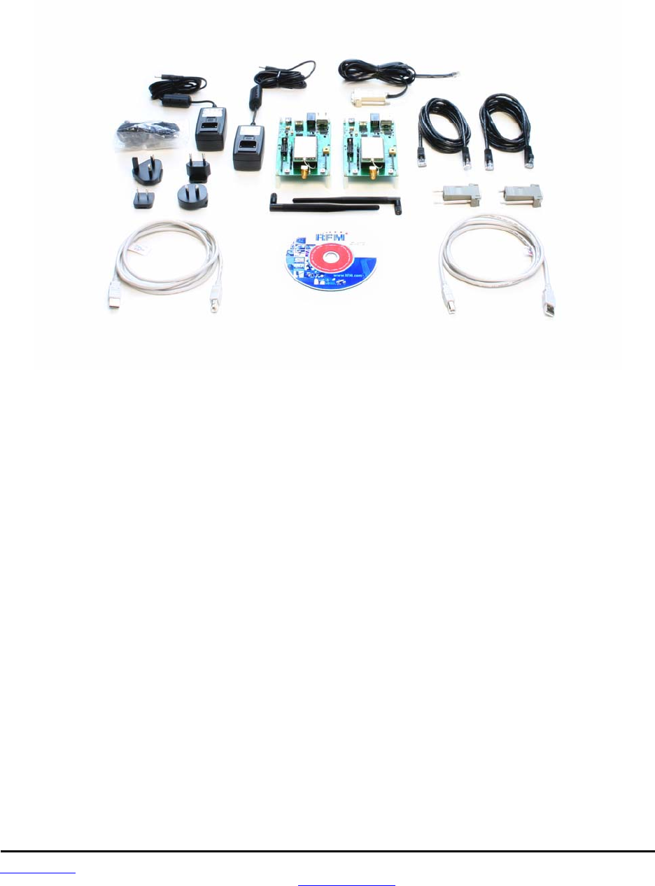
www.RFM.com Technical support +1.678.684.2000 Page 53 of 86
©2010 by RF Monolithics, Inc. E-mail: tech_sup@rfm.com DNT90 Integration Guide - 10/25/10
8.0 DNT90DK Developer’s Kit
Figure 8.0.1 shows the main contents of a DNT90DK Developer’s kit:
Figure 8.0.1
8.1 DNT90DK Kit Contents
Two DNT90P radios installed in DNT90 interface boards (labeled Base and Remote)
Two installed U.FL coaxial jumper cables and two 2 dBi dipole antennas
Two 9 V wall-plug power suppliers, 120/240 VAC, plus two 9 V batteries (not show above)
Two RJ-45/DB-9F cable assemblies, one RJ-11/DB-9F cable assembly, two A/B USB cables
One DNT90DK documentation and software CD
8.2 Additional Items Needed
To operate the kit, the following additional item is needed:
One PC with Microsoft Windows XP, Vista or Windows 7 operating system. The PC must be
equipped with a USB port or a serial port capable of operation at 9.6 kbps.
8.3 Developer’s Kit Default Operating Configuration
The default operating configuration of the DNT90DK developer’s kit is point-to-point with transparent seri-
al data at 9.6 kbps, 8N1. One DNT90P is preconfigured as a base and the other as a remote. Labels on
the bottom of the interface boards specify Base or Remote. The defaults can be overridden to test other
operating configurations using the DNT utility discussed in Section 8.5. The default RF power setting is
+16 dBm (40 mW). The RF power level can be set to +22 dBm (158 mw) as needed for longer range
operation.
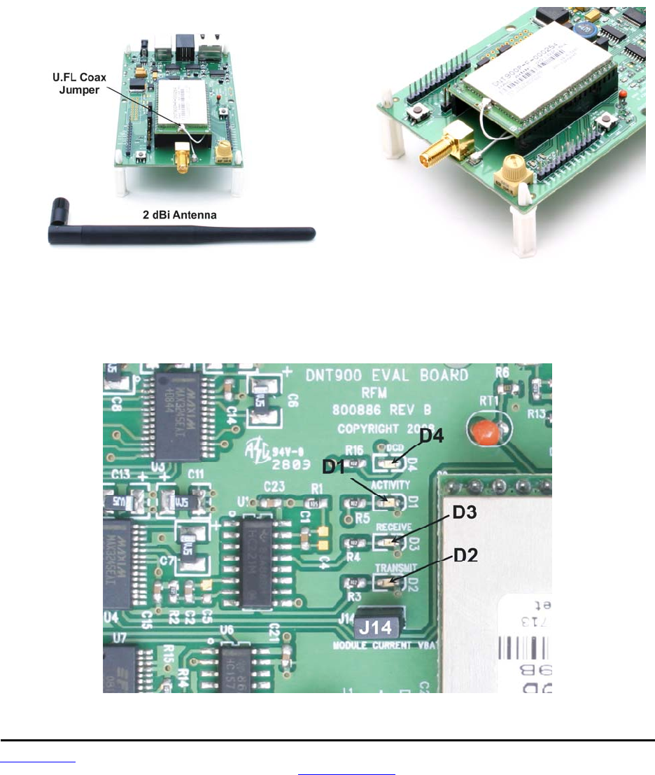
www.RFM.com Technical support +1.678.684.2000 Page 54 of 86
©2010 by RF Monolithics, Inc. E-mail: tech_sup@rfm.com DNT90 Integration Guide - 10/25/10
8.4 Developer’s Kit Hardware Assembly
Observe ESD precautions when handling the kit circuit boards. The components that make up a devel-
opment board are shown in Figure 8.4.1, and are shipped with the DNT90P radios and U.FL coax jumper
cables installed in the interface (evaluation) boards. If a DNT90P radio and/or the U.FL jumper cable has
been unplugged after receipt, confirm the DNT90P is correctly plugged into its interface board with the
radio oriented so that its U.FL connector is next to the U.FL connector on the interface board, as shown in
Figure 8.4.2. Also check the radio’s alignment in the socket on the interface board. No pins should be
hanging out over the ends of the connector. Next, install the dipole antennas.
Figure 8.4.1 Figure 8.4.2
As shown in Figure 8.4.3, confirm there is a jumper on pins J14. Note - this jumper can be removed and a
current meter connected across J14 to measure just the DNT90’s current consumption during operation.
Figure 8.4.3
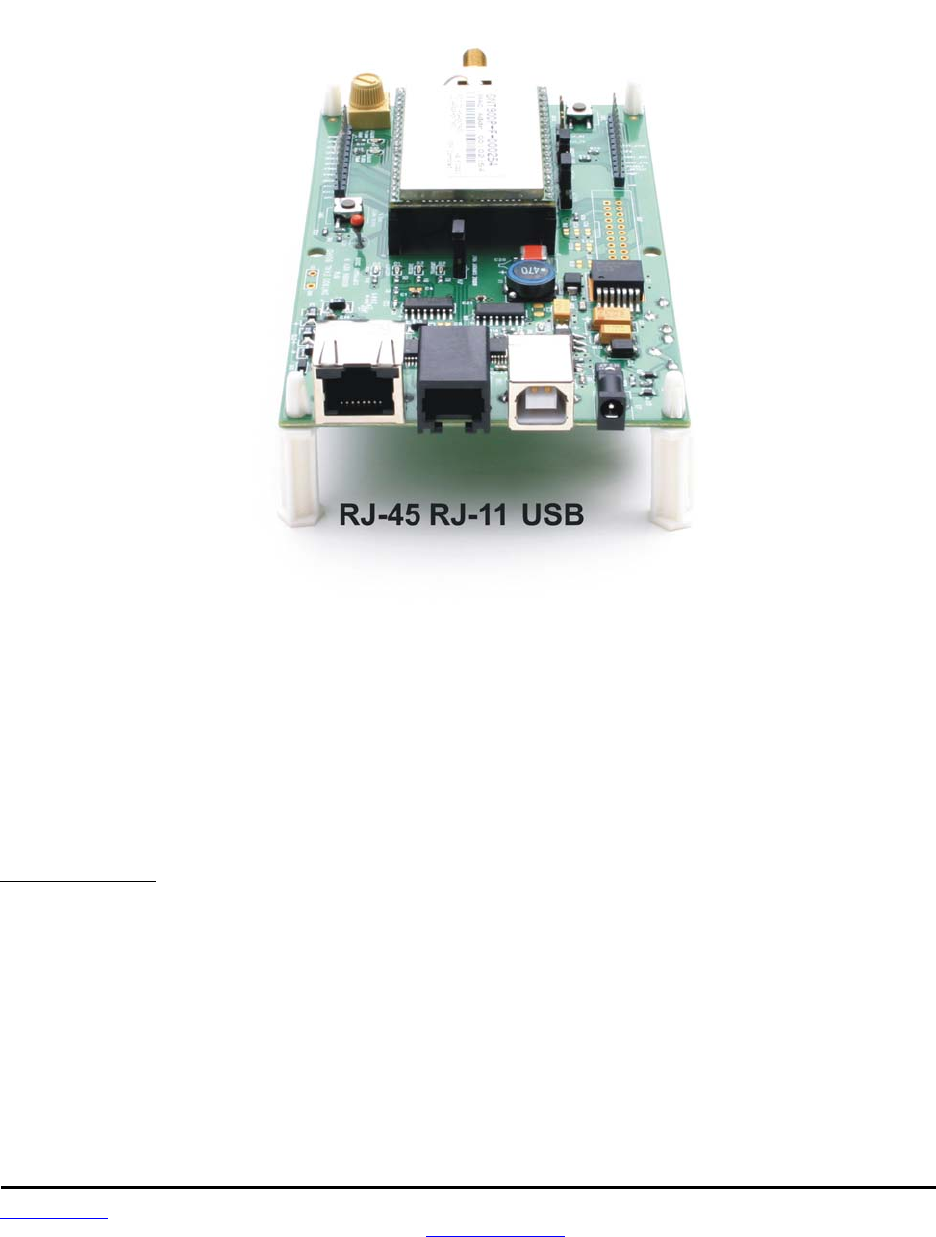
www.RFM.com Technical support +1.678.684.2000 Page 55 of 86
©2010 by RF Monolithics, Inc. E-mail: tech_sup@rfm.com DNT90 Integration Guide - 10/25/10
There are three serial connectors on the interface boards, as shown in Figure 8.4.4. The RJ-45 connector
provides a high-speed RS232 interface to the DNT90P’s main serial port. The USB connector provides an
optional interface to the radio’s main serial port. The RJ-11 connector provides a high-speed RS232 inter-
face to the radio’s diagnostic port. The DNT Demo utility program runs on the radio’s main port.
Figure 8.4.4
Many desktop PCs have a built-in serial port capable of operation at 9.6 kbps. The kit can be run satisfac-
torily at the 9.6 kbps data rate, but not at its fastest throughput. Use the RJ-45 to DB-9F cable assemblies
for serial port operation.
Optionally, the kit development boards can be run from USB ports. Plugging in the USB cable automati-
cally switches operation from the RJ-45 connector. The USB interface is based on an FT232RL serial-to-
USB converter IC manufactured by FTDI. The FT232RL driver files are located in the i386 and AMD64
folders on the kit CD, and the latest version of the drivers can downloaded from the FTDI website,
www.ftdichip.com. The drivers create a virtual COM port on the PC. Power the Base using one of the
supplied wall-plug power supplies. Next connect the Base to the PC with a USB cable. The PC will find
the new USB hardware and open a driver installation dialog box. Enter the letter of the drive holding the
kit CD and click Continue. The installation dialog will run twice to complete the FT232R driver installation.
8.5 DNT90 Utility Program
The DNT90 utility program requires only one PC for initial kit operation and sensor applications (ADC,
DAC and digital I/O). Two serial/USB ports are required for bidirectional serial communications. Section
8.7 below covers using the DNT Demo utility for initial kit operation and familiarization. Section 8.5.2 cov-
ers serial message communication and radio configuration.
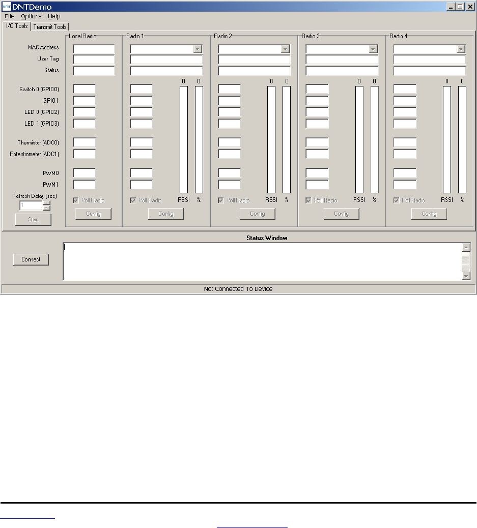
www.RFM.com Technical support +1.678.684.2000 Page 56 of 86
©2010 by RF Monolithics, Inc. E-mail: tech_sup@rfm.com DNT90 Integration Guide - 10/25/10
8.6 Initial Kit Operation
Create a file folder on the PC and copy the contents of the kit CD into the folder.
The DNT Demo utility program runs on the radio’s main port. The preferred PC interface is a serial port
capable of operating at 9.6 kbps or faster. As discussed above, the USB interface can also be used.
Connect the Base to the PC and power up the Base and the Remote development boards using the wall-
plug power supplies.
The DNT Demo utility program is located in the PC Programs folder. The DNT Demo requires no
installation and can be simply copied to the PC and run. Start the DNT Demo on the PC. The start-up
window is shown in Figure 8.6.1.
Figure 8.6.1
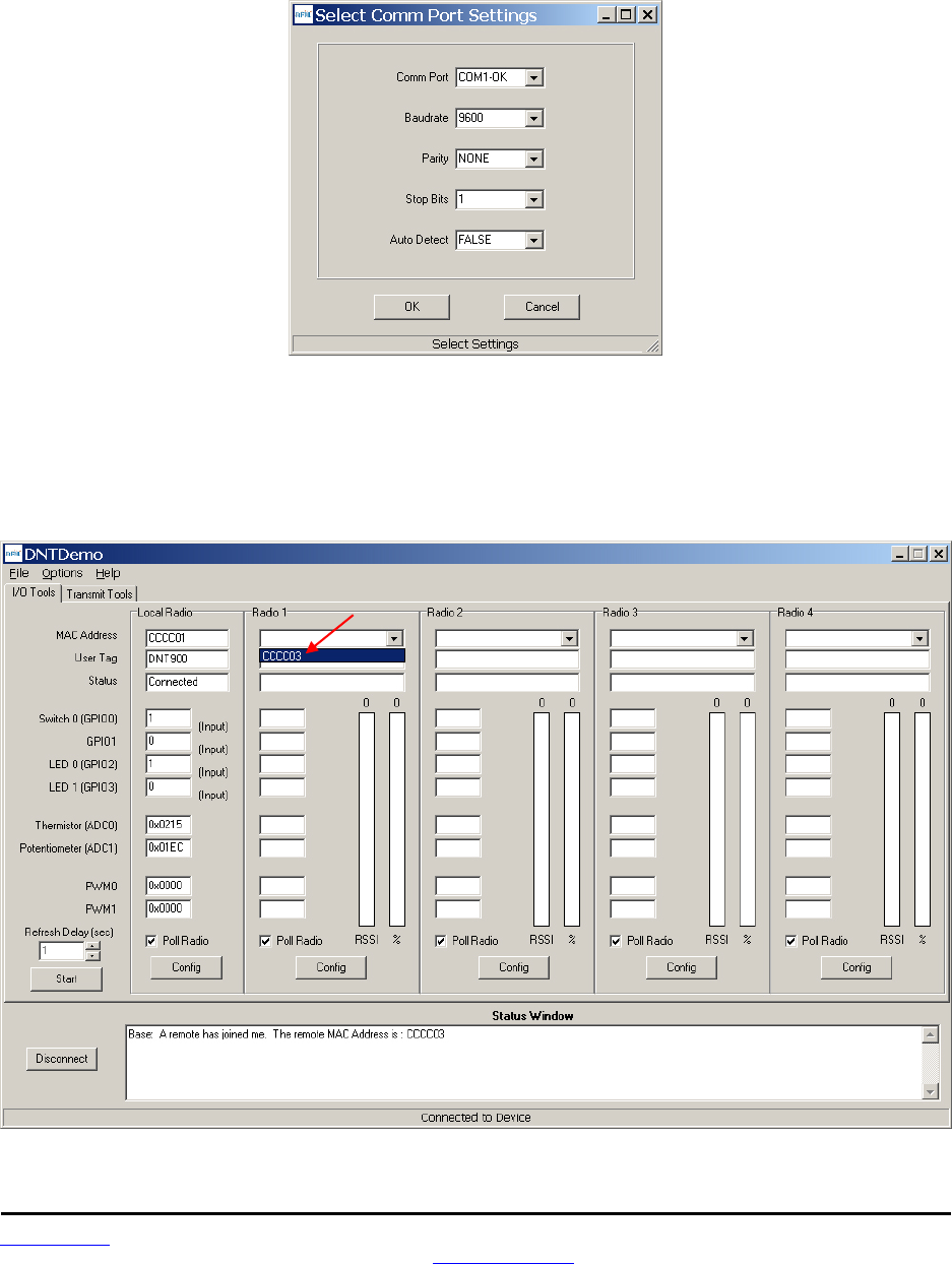
www.RFM.com Technical support +1.678.684.2000 Page 57 of 86
©2010 by RF Monolithics, Inc. E-mail: tech_sup@rfm.com DNT90 Integration Guide - 10/25/10
Click on Connect to open the Select Comm Port Settings dialog box, as shown in Figure 8.6.2. Set the
baud rate to 9600 (9.6 kbps). Set the CommPort to match the serial port connected to the Base, either the
hardware port or the USB virtual serial port. Then click OK to activate the serial connection.
Figure 8.6.2
At this point the Demo will collect data from the Base, filling in data in the Local Radio column on the
Demo window as shown in Figure 8.6.3. The Status Window should also show that the Remote has
joined the Base. Click on the drop-down box at the top of the Radio 1 column and select the MAC
Address for the Remote. Next press the Start button using the default 1 second Refresh Delay.
Figure 8.6.3
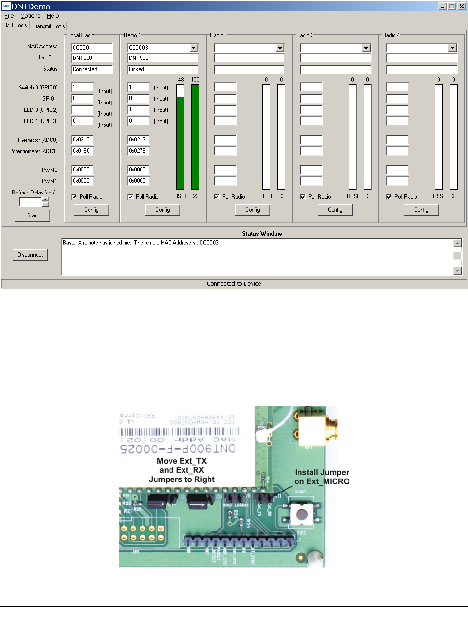
www.RFM.com Technical support +1.678.684.2000 Page 58 of 86
©2010 by RF Monolithics, Inc. E-mail: tech_sup@rfm.com DNT90 Integration Guide - 10/25/10
The Demo will display updated data on the Remote in the Radio 1 column, including bar graphs of RSSI
signal strength in dBm and percent packet success rate, as shown in Figure 8.6.4. Adjusting the large pot
on the Remote can be observed on the Potentiometer (ADC1) row.
Figure 8.6.4
To perform serial data loop back testing with the kit, move the two jumpers on the Remote board labeled
Ext_TX and Ext_RX to connect the center and right header pins. This disconnects the module's TX and
RX pins from the USB and RS-232C circuits. Use a banana clip or other short jumper to connect together
the two pins on the header labeled Ext_MICRO. See Figure 8.6.5. Attempting loop back testing by con-
necting Pins 2 and 3 of the DB9 serial connector can cause erratic behavior due to noise coupling from
the serial TX and RX lines into the weakly pulled up flow control lines on the board.
Figure 8.6.5
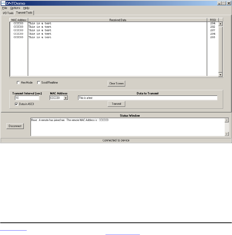
www.RFM.com Technical support +1.678.684.2000 Page 59 of 86
©2010 by RF Monolithics, Inc. E-mail: tech_sup@rfm.com DNT90 Integration Guide - 10/25/10
In order to turn off the DCD LED (D4) on the development board in sleep mode, the GpioSleepState pa-
rameter in the DNT90P has been set to 0xC0 rather than the factory default value of 0x00. If the DNT90P
is reset to its factory defaults, the DCD LED with remain on in sleep mode until the GpioSleepState is set
to 0xC0. See Section 7.5.7 for additional information on the GpioSleepState
parameter.
If any difficulty is encountered in setting up the DNT90DK development kit, contact RFM’s module tech-
nical support group. The phone number is +1.678.684.2000. Phone support is available from 8:30 AM to
5:30 PM US Eastern Time Zone, Monday through Friday. The E-mail address is tech_sup@rfm.com.
8.6.1 Serial Communication and Radio Configuration
Connect PCs to both the Base and the Remote for serial communication testing. Click the Stop button
under the Refresh Delay label on the I/O Tools tab and move to the Transmit Tools tab, as shown in
Figure 8.6.1.1.
Figure 8.6.1.1
Pressing the Transmit button on this screen sends the message in the Data to Transmit text box to the
selected MAC Address. Note that the MAC address a remote usually uses for the base is 0x000000.
Data sent to the local radio is displayed in the Received Data text box. Received data can be displayed
as ASCII (default) or in Hexadecimal format by checking the Hex Mode check box. When the Transmit
Interval is set to zero, Data to Transmit is sent once when the Transmit button is clicked. When the
Transmit Interval is set to a positive number, Pressing the Transmit button once will cause a transmission
each transmit interval (seconds) until the button is pressed again.
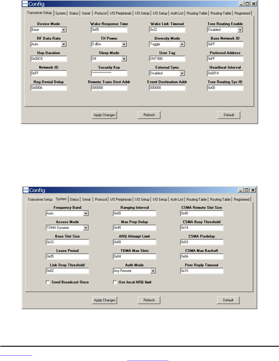
www.RFM.com Technical support +1.678.684.2000 Page 60 of 86
©2010 by RF Monolithics, Inc. E-mail: tech_sup@rfm.com DNT90 Integration Guide - 10/25/10
Returning to the I/O Tools tab, the multi-tab Configuration window for each radio can be accessed by
clicking on its Config button. The data presented on the first six tabs corresponds to configuration register
Banks 0 through 5 as discussed in Section 4.2 above, with the data on the next two tabs corresponding to
configuration register Bank 6, the data on the next tab corresponding to Bank 7, the data on the following
two tabs corresponding to Bank 8, and the data on the last tab corresponding to Bank 9.
Figure 8.6.1.2
The Transceiver Setup Tab is shown in Figure 8.6.1.2 and corresponds to Bank 0. The current values of
each Bank 0 parameter are displayed and can be updated by selecting from the drop-down menus or
entering data from the keyboard, and then pressing the Apply Changes button. Note that data is
displayed and entered in Big-Endian order. The Demo automatically reorders multi-byte data to and from
Little-Endian order when building or interpreting messages.
Figure 8.6.1.3
Figure 8.6.1.3 shows the System tab contents, corresponding to Bank 1. The current values of each pa-
rameter are displayed and can be updated by selecting from the drop-down menus or entering data
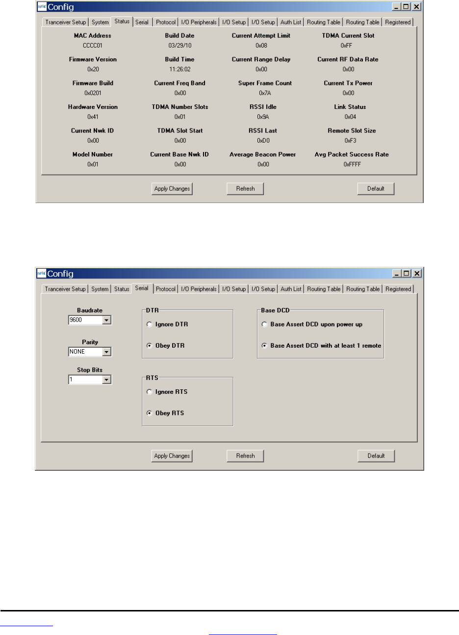
www.RFM.com Technical support +1.678.684.2000 Page 61 of 86
©2010 by RF Monolithics, Inc. E-mail: tech_sup@rfm.com DNT90 Integration Guide - 10/25/10
from the keyboard, and then pressing the Apply Changes button. Note that Bank 1 holds configuration
parameters for the base only except for ARQ_Mode, which applies to both the base and the remotes.
Figure 8.6.1.4
Figure 8.6.1.5 shows the Status tab contents, corresponding to Bank 2. Note the Status tab contains
read-only parameters.
Figure 8.6.1.5
Figure 8.6.1.5 shows the Serial tab contents corresponding to Bank 3. The values shown are the defaults
for serial port operation.
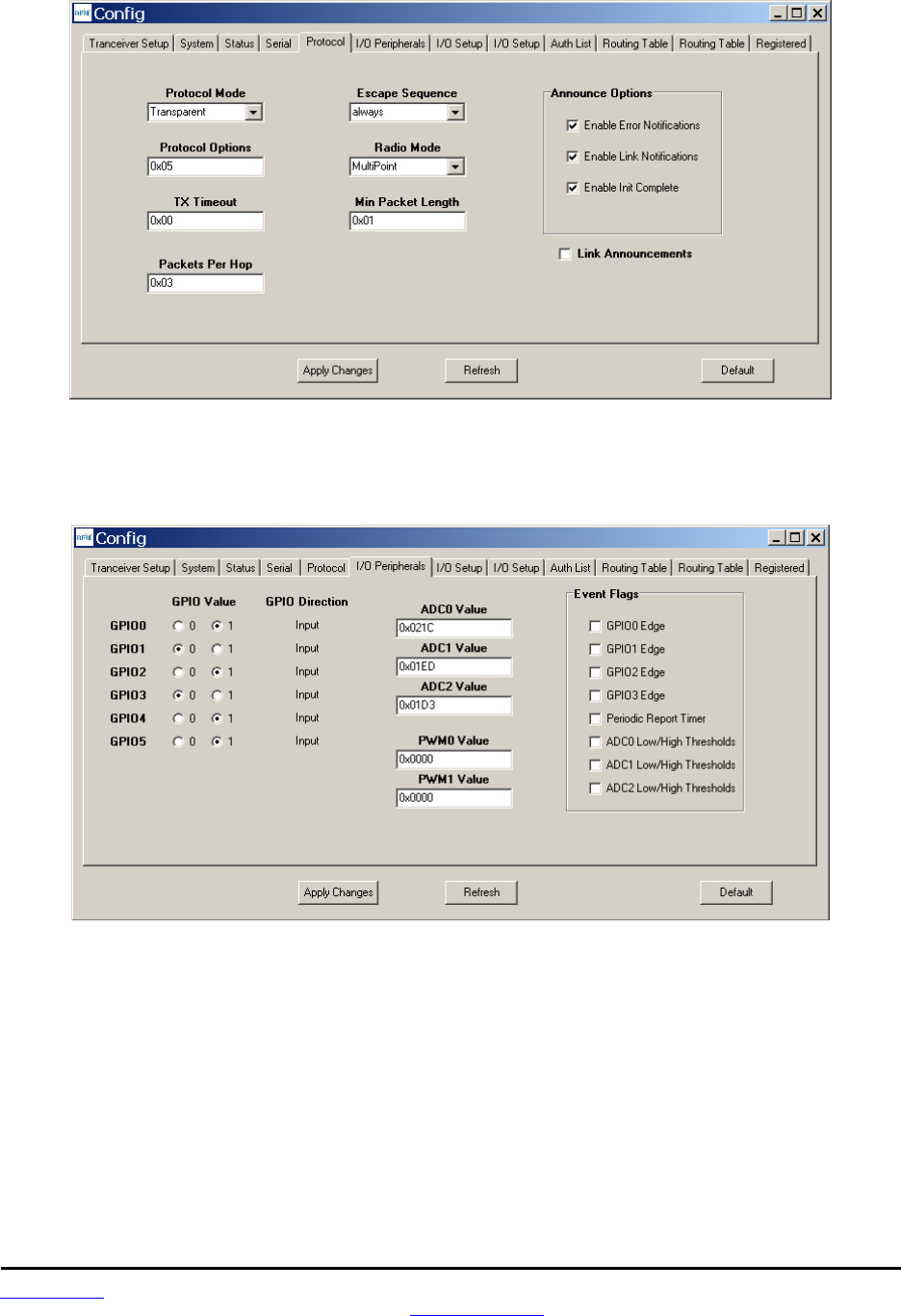
www.RFM.com Technical support +1.678.684.2000 Page 62 of 86
©2010 by RF Monolithics, Inc. E-mail: tech_sup@rfm.com DNT90 Integration Guide - 10/25/10
Figure 8.6.1.6
Figure 8.6.1.6 shows the Protocol tab contents, corresponding to Bank 4. Transparent data serial com-
munication is currently chosen.
Figure 8.6.1.7
Figure 8.6.1.7 shows the I/O Peripherals tab contents, corresponding to Bank 5. GPIO ports 1 and 3 are
logic high, GPIO ports 0, 2, 4 and 5 are logic low. The 10-bit ADC input readings and PWM output set-
tings are given in Big-Endian byte order. Event flags are presented on the right side of the window.
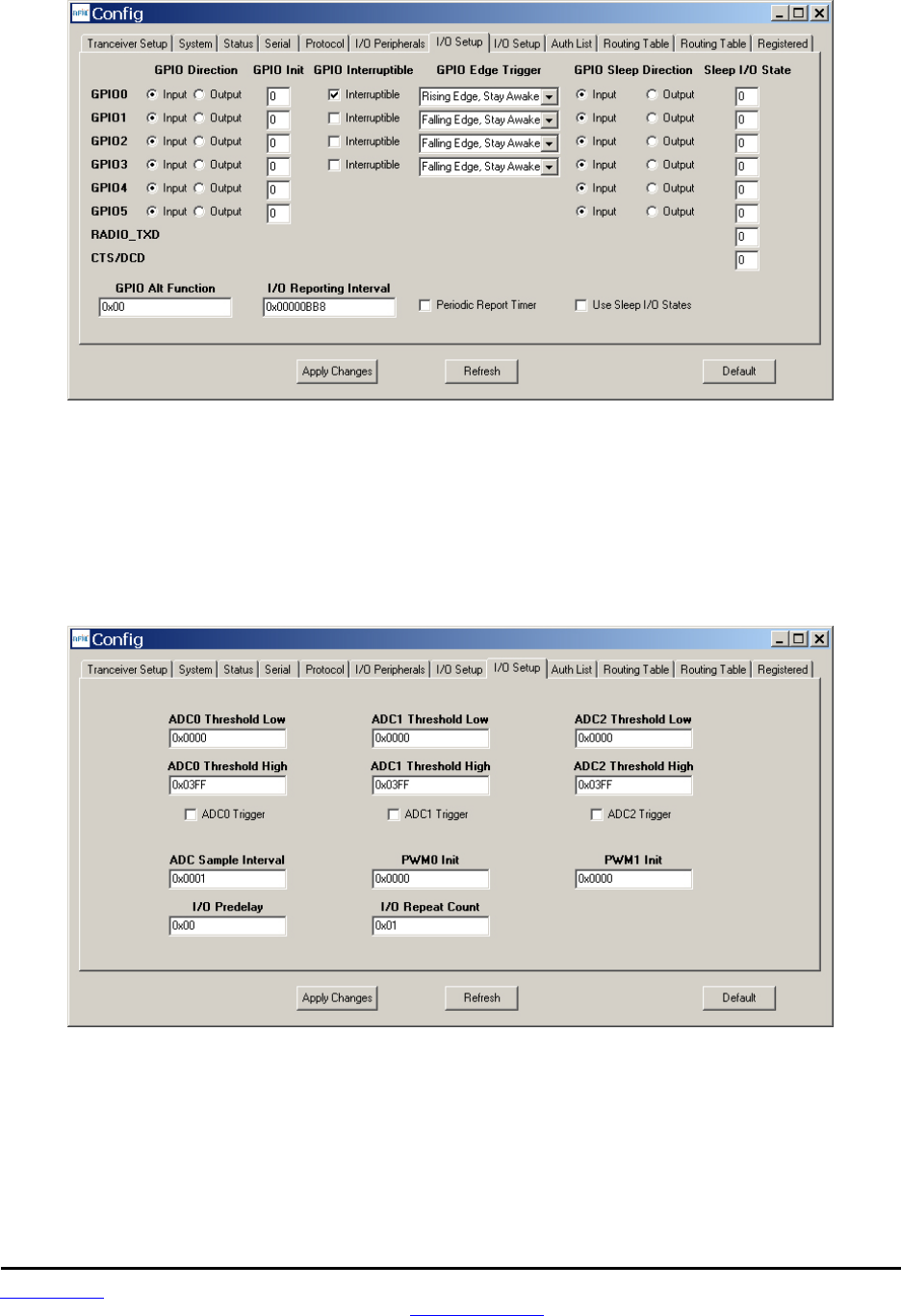
www.RFM.com Technical support +1.678.684.2000 Page 63 of 86
©2010 by RF Monolithics, Inc. E-mail: tech_sup@rfm.com DNT90 Integration Guide - 10/25/10
Figure 8.6.1.8
Figure 8.6.1.8 shows the first I/O Setup tab contents, corresponding to Bank 6 GPIO parameters. This tab
allows the direction of the GPIO ports to be set both for active and sleep modes, and in the case of GPIO
outputs, the initial power up states and sleep mode states to be set. When GPIO ports 0 - 3 are confi-
gured as inputs, event interrupts can be set for them with check boxes. The type of interrupt trigger is se-
lected from the drop-down boxes to the right of the check boxes. GPIO alternate function, periodic I/O
reporting, reporting interval and enable/disable sleep I/O states can also be specified under this tab.
Figure 8.6.1.9
Figure 8.6.1.9 shows the second I/O Setup tab contents, corresponding to Bank 6 ADC input and PWM
output parameters. The ADC sampling interval, high and low thresholds for event reporting and event re-
porting triggers on each ADC channel can be set, along with the start-up output values for each PWM
(DAC) channel. The event reporting predelay and repeat count parameters can also be set from this tab.
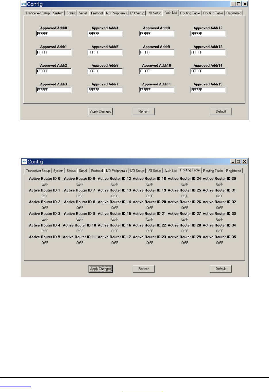
www.RFM.com Technical support +1.678.684.2000 Page 64 of 86
©2010 by RF Monolithics, Inc. E-mail: tech_sup@rfm.com DNT90 Integration Guide - 10/25/10
Figure 8.6.1.10
Figure 8.6.1.11 shows the Auth List tab, where the MAC addresses of the remotes authorized to join the
network in AuthMode 1 are input into Bank 7.
Figure 8.6.1.11
Figure 8.6.1.11 shows the first Routing Table tab, which displays part of the contents of Bank 8. This
bank contains the store and forward active router ID table, which is maintained by a base for its system. It
describes the organization of all active routers in the system. This table is used by the base and the rou-
ters to determine which direction to send a packet.
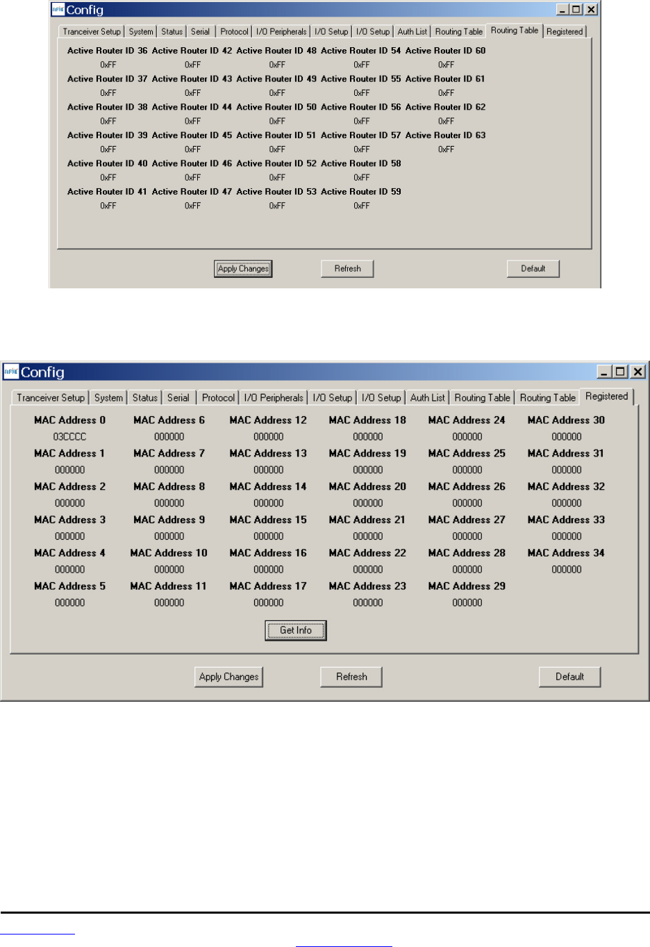
www.RFM.com Technical support +1.678.684.2000 Page 65 of 86
©2010 by RF Monolithics, Inc. E-mail: tech_sup@rfm.com DNT90 Integration Guide - 10/25/10
Figure 8.6.1.12
Figure 8.6.1.12 shows the second Routing Table tab, which displays the rest of the contents of Bank 8.
Figure 8.6.1.13
Figure 8.6.1.13 shows the Registered tab, which displays the first seven parameters in Bank 9. This bank
holds the MAC addresses of all radios registered to a base or router. Up to 126 MAC addresses can be
registered. Each bank parameter can hold up to five MAC addresses, with each MAC address containing
three bytes. Three-byte segments in a parameter not holding a MAC address with hold a null address:
0x000000. In a remote, this bank will contain only null addresses.
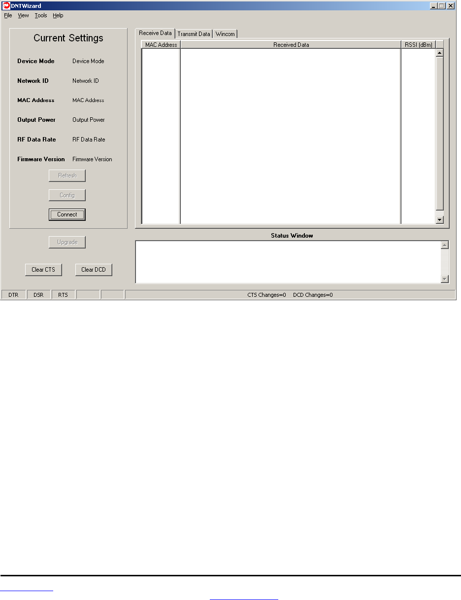
www.RFM.com Technical support +1.678.684.2000 Page 66 of 86
©2010 by RF Monolithics, Inc. E-mail: tech_sup@rfm.com DNT90 Integration Guide - 10/25/10
8.7 DNT Wizard Program
The DNT Wizard is a complementary program to the DNT90 Utility that emphasizes the details of serial
communication between a DNT90 and its host computer. The DNT90 Wizard start-up window is shown in
Figure 8.7.1.
Figure 8.7.1
The DNT Wizard uses three Function keys:
F1 toggles the SLEEP/DTR input to the DNT90 on and off. This allows the DNT90 to be reset.
F2 toggles the RTS input to the DNT90 on and off, providing manual flow control.
F6 toggles test transmissions on and off. The test message is “This is a test”.
The DNT Wizard also includes the ability to log messages to and from the DNT90. This feature is espe-
cially useful in confirming the format of protocol command and reply messages. Control of the log file is
under the View menu. Logging is enabled by default. The log file created is logfile.dat, and is in ASCII text
format. An example log is shown at the end of this section.
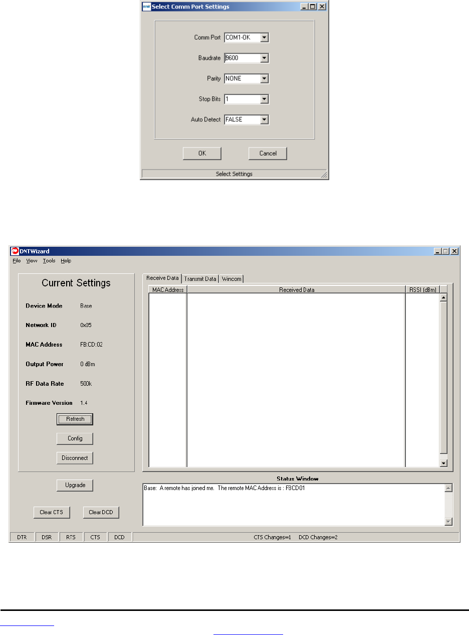
www.RFM.com Technical support +1.678.684.2000 Page 67 of 86
©2010 by RF Monolithics, Inc. E-mail: tech_sup@rfm.com DNT90 Integration Guide - 10/25/10
Click on Connect to open the Select Comm Port Settings dialog box, as shown in Figure 8.7.2. Set the
baud rate to 9600 (9.6 kbps). Set the CommPort to match the serial port connected to the Base, either the
hardware port or the USB virtual serial port. Then click OK to activate the serial connection.
Figure 8.7.2
At this point the Wizard will collect data from the Base, filling in data under Current Settings as shown in
Figure 8.7.3. The Status Window should also show that the Remote has joined the Base.
Figure 8.7.3
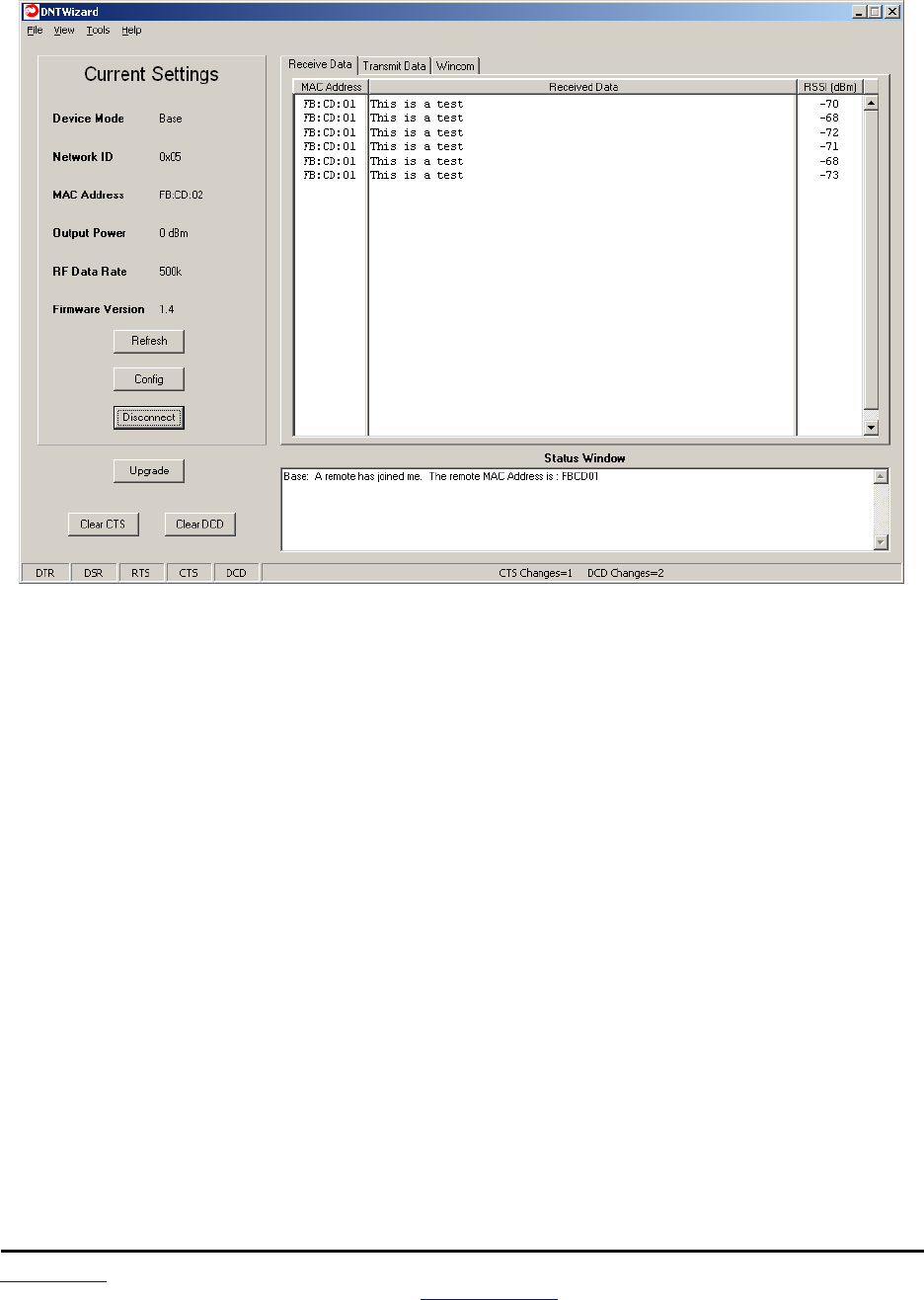
www.RFM.com Technical support +1.678.684.2000 Page 68 of 86
©2010 by RF Monolithics, Inc. E-mail: tech_sup@rfm.com DNT90 Integration Guide - 10/25/10
There are three tabs on the DNT Wizard main window: Receive Data, Transmit Data and Wincom.
Figure 8.7.4
Received messages are displayed in the Receive Data tab, along with the MAC address of the sender
and the RSSI (signal strength) of the received message in dBm. See Figure 8.7.4.
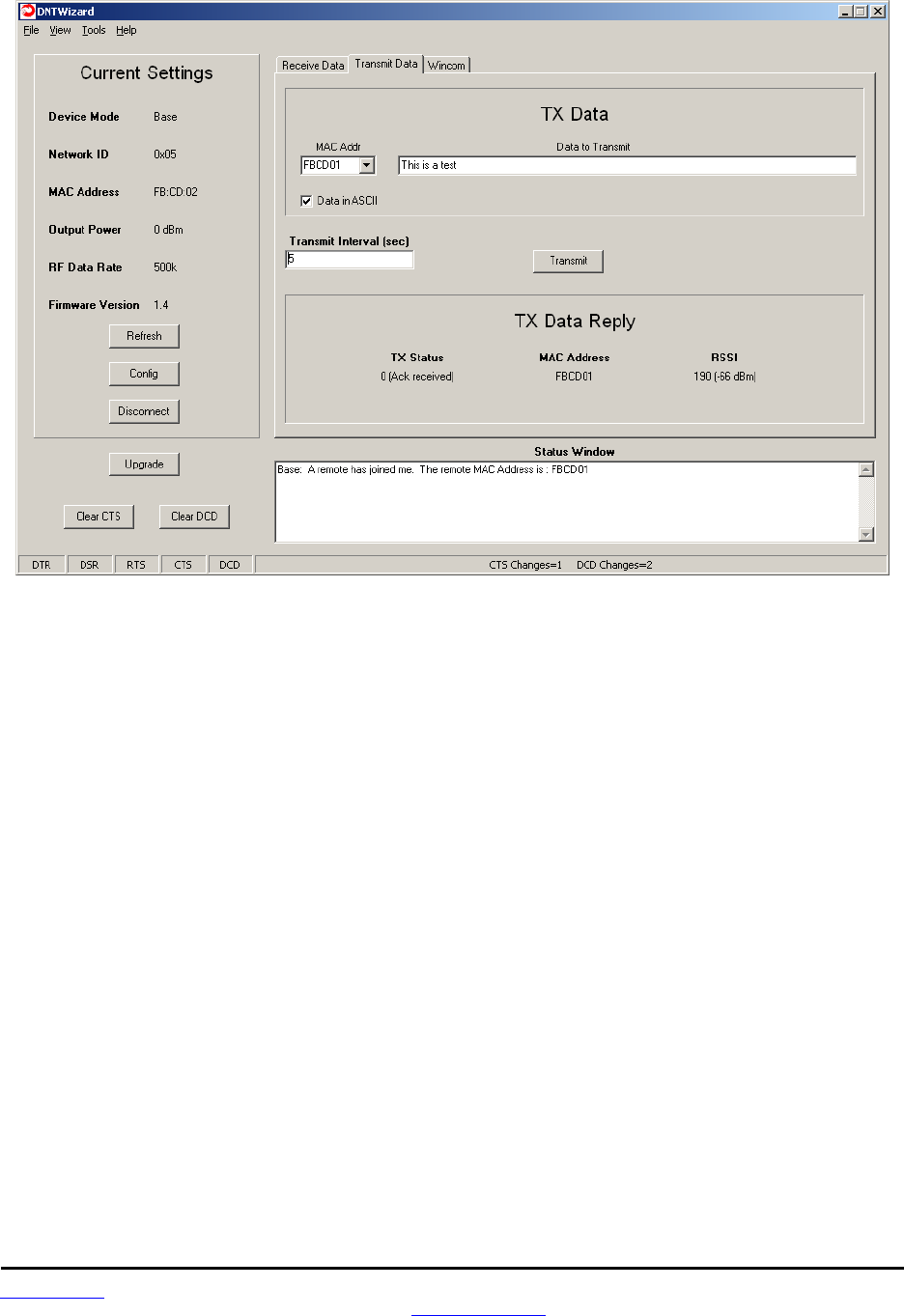
www.RFM.com Technical support +1.678.684.2000 Page 69 of 86
©2010 by RF Monolithics, Inc. E-mail: tech_sup@rfm.com DNT90 Integration Guide - 10/25/10
Figure 8.7.5
The Transmit Data tab is shown in Figure 8.7.5. The message to send is input in the Data to Transmit text
box. The address to send the message can be chosen or input in the MAC Addr drop-down box. Note
that the address for the base is always 0x000000. If the Transmit Interval is set to 0, the message is sent
once each time the Transmit button is clicked. When the Transmit Interval is set to an integer greater than
zero, the message will sent at the beginning of each interval until the Stop button (was Transmit button) is
clicked. The status of each transmission is shown below TX Data Reply. Figure 8.7.5 shows that the
transmitted message was ACKed, with the received signal strength of the ACK -66 dBm.
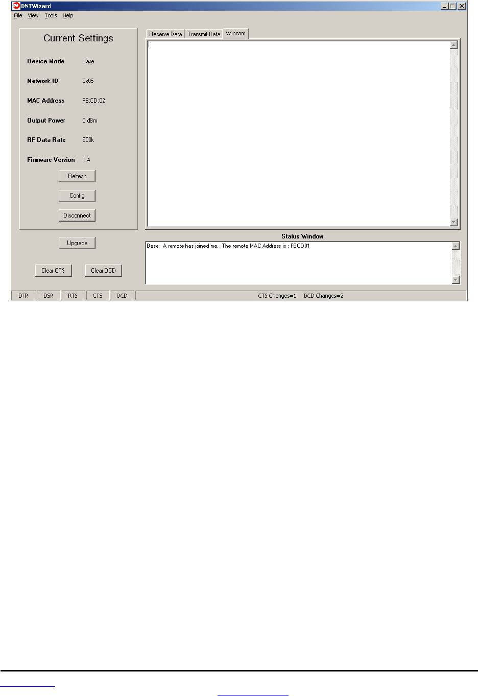
www.RFM.com Technical support +1.678.684.2000 Page 70 of 86
©2010 by RF Monolithics, Inc. E-mail: tech_sup@rfm.com DNT90 Integration Guide - 10/25/10
Figure 8.7.6
As shown in Figure 8.7.6, the Wincom tab provides the basic functionality of a serial terminal program.
Messages typed in are sent, and messages received are appended to the bottom of the on-screen text.
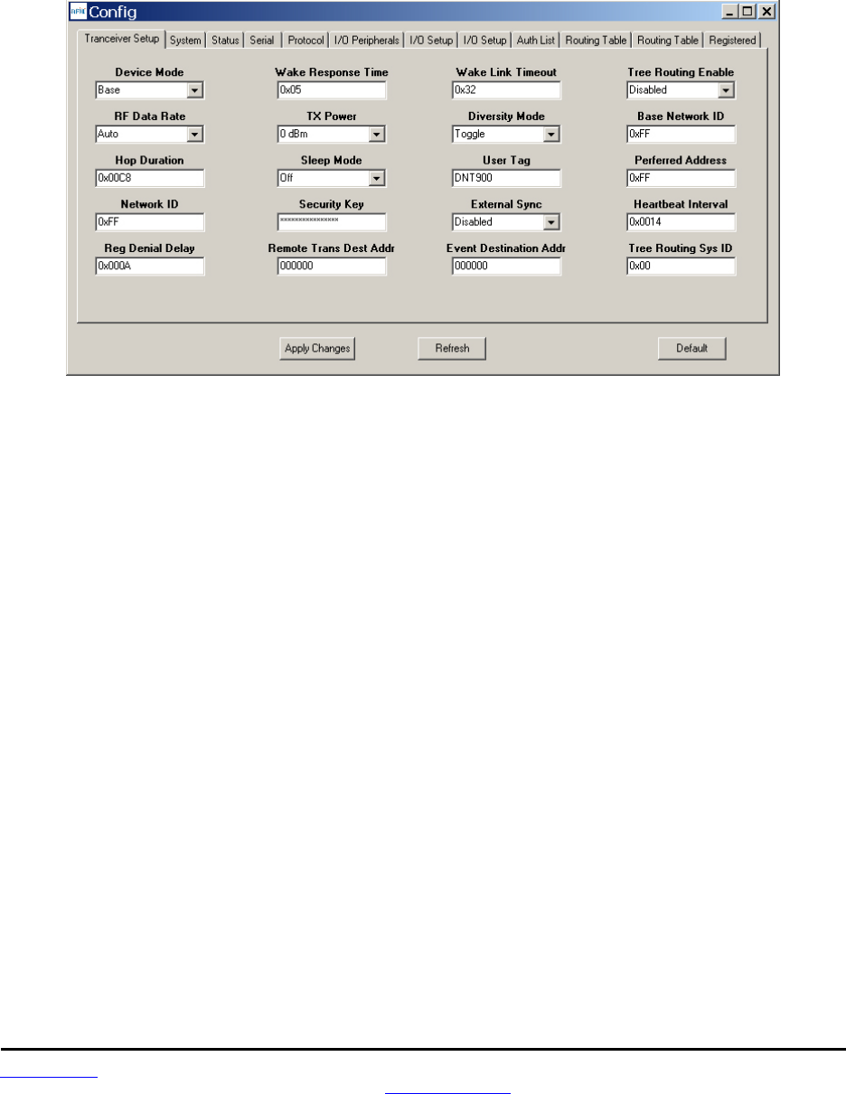
www.RFM.com Technical support +1.678.684.2000 Page 71 of 86
©2010 by RF Monolithics, Inc. E-mail: tech_sup@rfm.com DNT90 Integration Guide - 10/25/10
The multi-tab Configuration window is accessed by clicking on its Config button. The data presented on
the first six tabs corresponds to configuration register Banks 0 through 5 as discussed in Section 7.5
above, with the data on the next two tabs corresponding to configuration register Bank 6, the data on the
next tab corresponding to Bank 7, the data on the following two tabs corresponding to Bank 8, and the
data on the last tab corresponding to Bank 9.
Figure 8.7.7
The Configuration window in the DNT Wizard is identical the Configuration window in the DNT Demo. See
Figures 8.6.1.2 through 8.6.1.13 for Configuration window details.
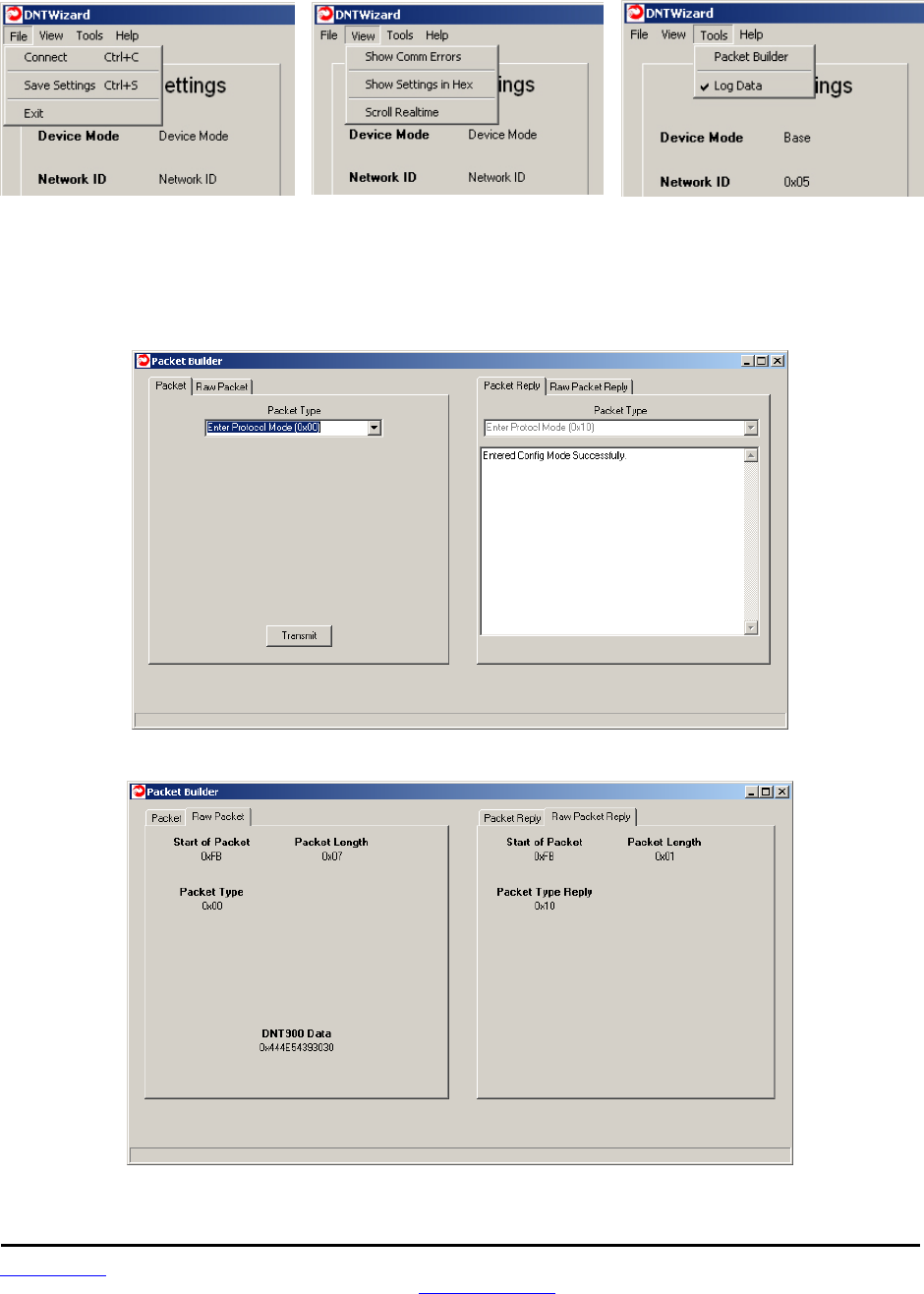
www.RFM.com Technical support +1.678.684.2000 Page 72 of 86
©2010 by RF Monolithics, Inc. E-mail: tech_sup@rfm.com DNT90 Integration Guide - 10/25/10
Details of the File, View and Tools menus are shown in Figure 8.7.8.
Figure 8.7.8
The Tools menu contains two very useful items. Packet Builder opens the window shown in Figure 8.7.9.
On the left, the Packet Type drop-down box provides a selection of all packet types used in the DNT90
protocol. On the right, the reply packet types are presented.
Figure 8.7.9
Figure 8.7.10

www.RFM.com Technical support +1.678.684.2000 Page 73 of 86
©2010 by RF Monolithics, Inc. E-mail: tech_sup@rfm.com DNT90 Integration Guide - 10/25/10
Figure 8.7.10 shows the Raw Packet and Raw Packet Reply tabs. Components of the protocol messages
are shown in hexadecimal format.
Log Data controls the log file. Logging is enabled by default. The log file created is logfile.dat, and is in
ASCII text format. An example log is shown below:
New Data------------------------------------------
12/7/2008 | 7:05:39 AM
DNT Wizard Version 0.92
Sent Data : FB 07 00 44 4E 54 35 30 30 (Enter Protocol Mode)
Recv Data : FB 01 10 (Enter Protocol Mode Reply)
Sent Data : FB 04 03 00 00 2C (Get Register)
Recv Data : FB 30 13 00 00 2C 01 FF 68 01 05 2A 2A 2A 2A 2A 2A 2A 2A 2A 2A 2A 2A 2A 2A 2A 2A
00 05 32 00 00 02 02 44 4E 54 39 30 30 00 00 00 00 00 00 00 00 00 00 (Get Register Reply)
Sent Data : FB 04 03 00 01 0E (Get Register)
Recv Data : FB 12 13 00 01 0E 00 03 D2 05 00 05 08 03 0A 0E 0C 30 14 00 (Get Register Reply)
Sent Data : FB 04 03 00 02 27 (Get Register)
Recv Data : FB 2B 13 00 02 27 02 CD FB 00 05 00 00 04 47 08 00 FF 42 14 49 01 18 00 A9 00 00
05 00 31 31 2F 31 38 2F 30 38 31 36 3A 30 30 3A 35 30 (Get Register Reply)
Sent Data : FB 04 03 00 03 04 (Get Register)
Recv Data : FB 08 13 00 03 04 04 00 00 07 (Get Register Reply)
Sent Data : FB 04 03 00 04 08 (Get Register)
Recv Data : FB 0C 13 00 04 08 00 05 05 01 07 00 02 00 (Get Register Reply)
Sent Data : FB 04 03 00 05 12 (Get Register)
Recv Data : FB 16 13 00 05 12 01 00 00 00 01 01 F5 01 FD 01 DA 01 00 00 00 00 00 00 (Get
Register Reply)
Sent Data : FB 04 03 00 06 1E (Get Register)
Recv Data : FB 22 13 00 06 1E 00 00 00 01 00 00 00 00 00 00 00 01 00 00 00 FF 03 00 00 FF 03
00 00 FF 03 01 B8 0B 00 00 (Get Register Reply)
Recv Data : FB 07 27 A2 01 CD FB 01 01 (Announce)
Sent Data : FB 12 05 01 CD FB 54 68 69 73 20 69 73 20 61 20 74 65 73 74 (TX Data)
Recv Data : FB 06 15 00 01 CD FB BB (TX Data Reply)
Sent Data : FB 12 05 01 CD FB 54 68 69 73 20 69 73 20 61 20 74 65 73 74 (TX Data)
Recv Data : FB 06 15 00 01 CD FB B6 (TX Data Reply)
Sent Data : FB 12 05 01 CD FB 54 68 69 73 20 69 73 20 61 20 74 65 73 74 (TX Data)
Recv Data : FB 06 15 00 01 CD FB BA (TX Data Reply)
Sent Data : FB 12 05 01 CD FB 54 68 69 73 20 69 73 20 61 20 74 65 73 74 (TX Data)
Recv Data : FB 06 15 00 01 CD FB B8 (TX Data Reply)
Sent Data : FB 12 05 01 CD FB 54 68 69 73 20 69 73 20 61 20 74 65 73 74 (TX Data)
Recv Data : FB 06 15 00 01 CD FB B3 (TX Data Reply)
The log file is especially useful in confirming the format of specific protocol commands and replies.
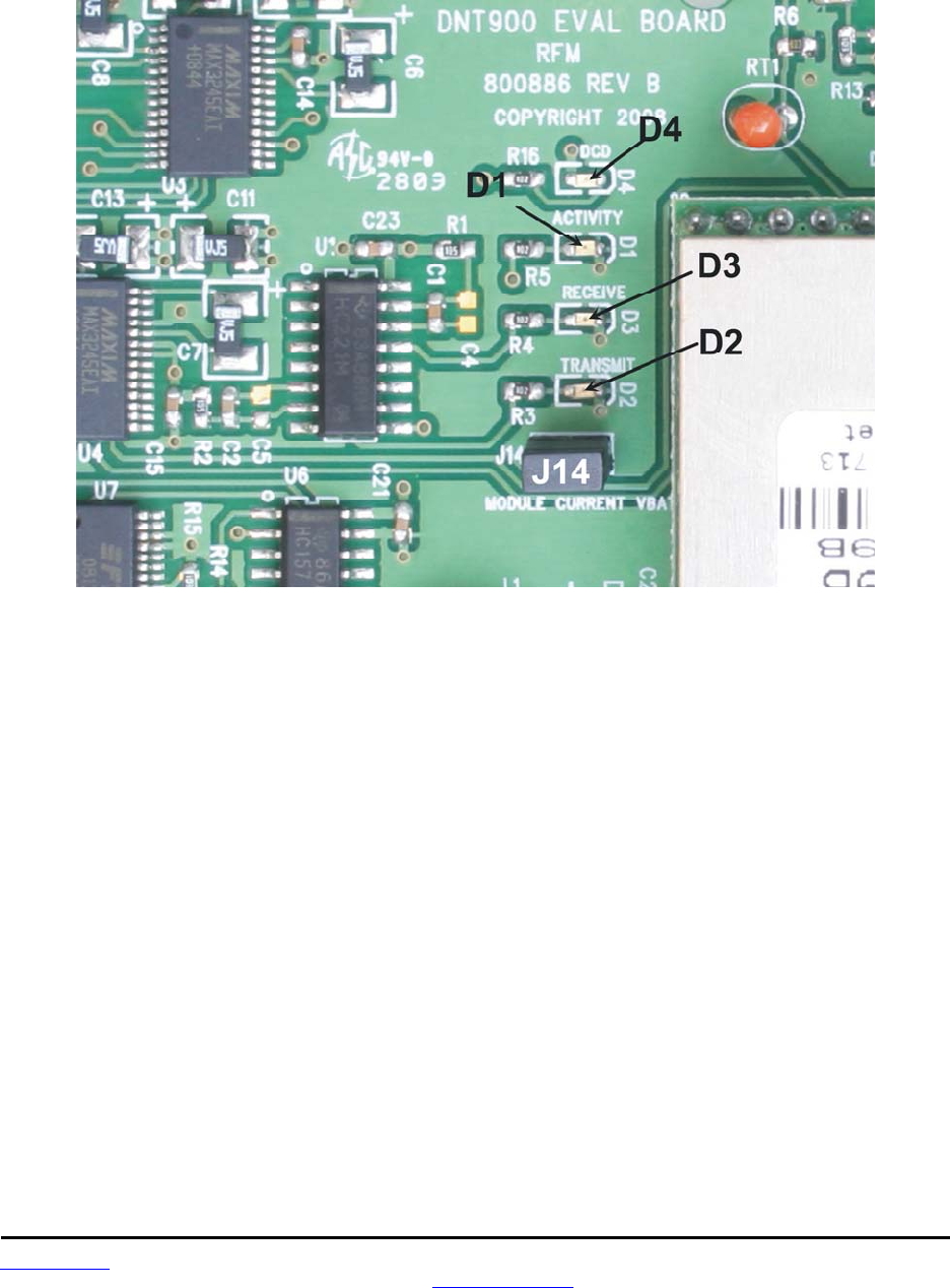
www.RFM.com Technical support +1.678.684.2000 Page 74 of 86
©2010 by RF Monolithics, Inc. E-mail: tech_sup@rfm.com DNT90 Integration Guide - 10/25/10
8.8 DNT90 Interface Board Features
The location of LEDs D1 through D4 and jumper pin set J14 are shown in Figure 8.8.1.
Figure 8.8.1
Amber DCD LED D4 illuminates on a remote to indicate it is registered with the base and can participate
in RF communications. DCD LED D4 illuminates on the base when one or more remotes are registered to
it, unless the base has been configured to assert DCD on power up. In this case it will be on as long as
the dev board is powered. Green Activity LED D1 illuminates when transmitting or receiving RF data. Red
Receive LED D3 illuminates when sending received data through the serial port to the PC. Green Trans-
mit LED D2 illuminates when the PC sends data through the serial port to be transmitted. Jumper pin set
J14 is provided to allow measurement of the DNT90P current. For normal operation J14 has a shorting
plug installed.
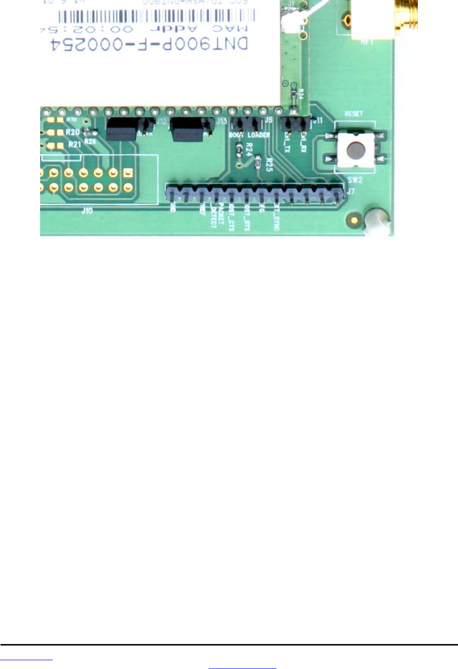
www.RFM.com Technical support +1.678.684.2000 Page 75 of 86
©2010 by RF Monolithics, Inc. E-mail: tech_sup@rfm.com DNT90 Integration Guide - 10/25/10
Figure 8.8.2
Figure 8.8.2 shows the connectors to the right of the DNT90P mounting socket. Jumper pin sets J12 and
J13 normally have shorting plugs installed as shown in Figure 8.8.2, which connects the DNT90P RA-
DIO_TXD and RADIO_RXD pins to the respective serial data lines on the evaluation board. It is possible
to connect directly to RADIO_TXD and RADIO_RXD by moving the jumpers over. In this case, J11-1 is
the input for transmitted data and J11-2 is the output for received data. Note this a 3 V logic interface. The
DNT90 has its own boot loader utility that allows the protocol firmware to be installed with a terminal pro-
gram that supports YMODEM. Pin strip J7 provides access to various DNT90 pins as shown on the
silkscreen. Pressing switch SW2 will reset the DNT90P.
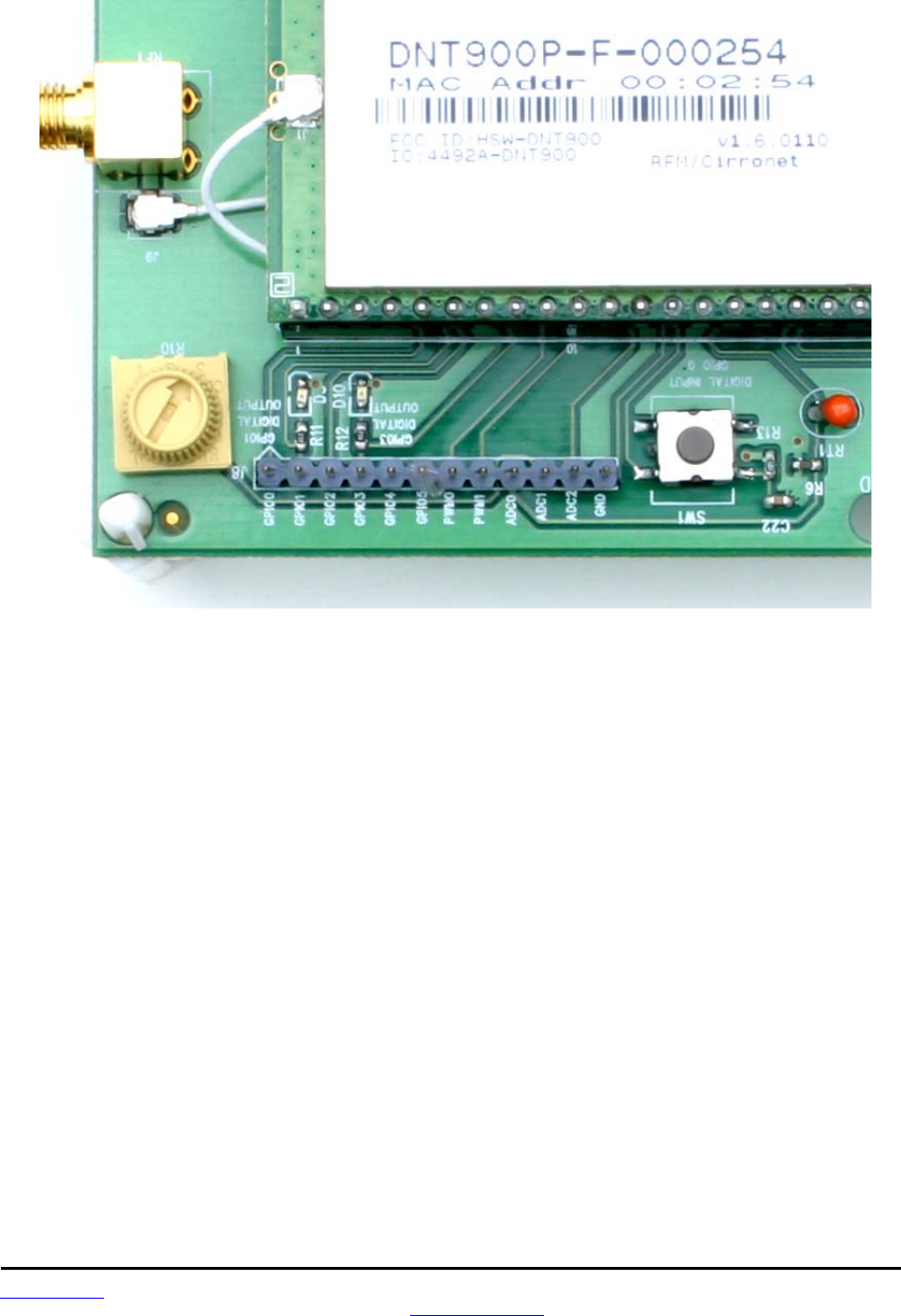
www.RFM.com Technical support +1.678.684.2000 Page 76 of 86
©2010 by RF Monolithics, Inc. E-mail: tech_sup@rfm.com DNT90 Integration Guide - 10/25/10
Figure 8.8.3
Figure 8.8.3 shows the connectors to the left of the DNT90P mounting socket. Pressing switch SW1
switches GPIO0 from logic high to logic low. Pin strip J8 provides access to various DNT90 pins as shown
on the silkscreen. The wiper of pot R10 drives the input of ADC1. Clockwise rotation of the pot wiper in-
creases the voltage. Thermistor RT1 is part of a voltage divider that drives ADC0. LED D5 illuminates
when GPIO1 is set as a logic high output. LED D10 illuminates when GPIO3 is set as a logic high. The
DNT90P interface board includes a 5 V regulator to regulate the input from the 9 V wall-plug power
supply. Note: do not attempt to use the 9 V wall-plug power supply to power the DNT90P directly. The
maximum allowed voltage input to the DNT90P is 5.5 V.

www.RFM.com Technical support +1.678.684.2000 Page 77 of 86
©2010 by RF Monolithics, Inc. E-mail: tech_sup@rfm.com DNT90 Integration Guide - 10/25/10
9.0 Troubleshooting
DNT90 not responding - make sure SLEEP/DTR is not asserted (logic low) to bring the radio out of sleep
mode.
Can not enter protocol mode - make sure the host data rate is correct. The DNT90 defaults to 9.6 kbps. If
using the EnterProtocolMode command, send the complete protocol format for this command.
A remote never detects carrier (DCD) - check that the base is running, and that the remote’s SystemNwk-
ID is the same as the base, and that the ParentNwkID parameter is the same as the base, or is set to
0xFF. Also make sure that the security keys are the same.
Carrier is detected, but no data appears to be received - make sure that /HOST_RTS is asserted to ena-
ble receive character flow.
Range is extremely limited - this is usually a sign of a poor antenna connection or the wrong antenna.
Check that the antenna is firmly connected. If possible, remove any obstructions near the antenna.
9.1 Diagnostic Port Commands
FSTAT <option> - enables a frequency-ordered channel activity status log.
Available options are:
0 - off
1 - on
For either a base or remote, FSTAT shows the DataTx (data packet transmitted), AckRx (ACK received)
and RegRx (registration or renewal request or reply received) activity status on each frequency with AS-
CII characters as follows:
‘.’ (0x2E) - no activity
‘1’ (0x31) - DataTx activity only
‘2’ (0x32) - AckRx activity only
‘3’ (0x33) - DataTx and AckRx activity
‘4’ (0x34) - RegRx activity only
‘5’ (0x35) - DataTx and RegRx activity
‘6’ (0x36) - AckRx and RegRx activity
‘7’ (0x37) - DataTx, AckRx and RegRx activity

www.RFM.com Technical support +1.678.684.2000 Page 78 of 86
©2010 by RF Monolithics, Inc. E-mail: tech_sup@rfm.com DNT90 Integration Guide - 10/25/10
A sample FSTAT output for 50 channel operation is shown below. The status data is order from the low-
est operating frequency on the left to the highest operating frequency on the right. An ASCII CR-LF termi-
nates each line. On most frequencies, DataTx and AckRx occur on the same frequency (‘3’). Occasionally
there is DataTx, AckRx and RegRx activity (‘7’), DataTx only activity (‘1’), or no activity (‘.’).
33333333333333333333333333133333333333333333333333
33333333333333333333333333333333333333333333333333
33333333333333333333373333133333333333333333333333
33333333333333333333333333333333333333333333333333
33313333333233333333333333333333.33333333333333333
INSTR <option>
Available options are:
0 - off
1 - on
For either a base or a remote, INSTR streams instrumentation packets including a time stamp and seven
data values. The time stamp is a string of four characters. The first three characters are ASCII represen-
tations of hexadecimal numbers. The fourth character is a ‘>’ character. Each time stamp count is 100 µs.
The time stamp rolls over to 0x000 after count 0xCE5. The content of the seven data values are detailed
below. ASCII representations of the hexadecimal value of each byte are output, separated by space cha-
racters:
Byte 0: current channel, 0 to 49; frequency is 902.75 MHz + current channel * 0.5 MHz
Byte 1: same data as FSTAT 1, except no activity is 0x30
Byte 2: RSSI_Last, RSSI of last RF packet received in dBm, 8-bit signed value
Byte 3: RSSI_Idle, most recent RSSI value on a channel with no expected activity
Byte 4: Range delay estimate, remote only, 3.1 µs/tick
Byte 5: Status bits 1
b7.. b4 - reserved
b3 - inbound data RF flow control, 1 = device has disabled RF flow
b2 - outbound data RF flow control, 1 = base has disabled RF flow
b1 - /HOST_CTS, status of CTS line, 1 = hold
b0 - /DCD, link LED on; on a remote indicates registration with base, on the base it indi-
cates at least on remote is registered (default)
Byte 6: Status bits 0
b7 - CSMA channel busy
b6 - Parser/CRC error
b5 - valid RF packet received (any type)
b4 - DataRx, data packet received
b3 - RegTx, registration or renewal request or reply transmitted
b2 - RegRx, registration or renewal request or reply received
b1 - AckRx, ACK received
b0 - DataTx, data packet transmitted
A sample INSTR output is shown below.
896> 26 01 DA 98 00 01 01
940> 0A 03 DA 9C 00 01 23
9E2> 1D 03 DA 99 00 03 23
A8A> 30 01 D6 9F 00 03 21
B36> 11 03 D6 99 00 03 23

www.RFM.com Technical support +1.678.684.2000 Page 79 of 86
©2010 by RF Monolithics, Inc. E-mail: tech_sup@rfm.com DNT90 Integration Guide - 10/25/10
Looking a the first line in detail:
896> 26 01 DA 98 00 01 01
The time stamp is 0x896>
Byte 0, 0x26, indicates the channel of operation is 38 (decimal)
Byte 1, 0x01, is the same status data as FSTAT data above. In this case, DataTx activity only.
Byte 2, 0xDA, is the last RSSI value, -38 dBm
Byte 3, 0x98, is the RSSI idle value, -100 dBm
Byte 4, 0x00, is the range delay estimate (remote only). The remote is very close to the base.
Byte 5, 0x01, provides the serial port status - /HOST_CTS is high
Byte 6, 0x01, provides the communication status - DataTx active only. Note that this byte provides addi-
tional status bytes compared to byte index 1.

www.RFM.com Technical support +1.678.684.2000 Page 80 of 86
©2010 by RF Monolithics, Inc. E-mail: tech_sup@rfm.com DNT90 Integration Guide - 10/25/10
10.0 Appendices
10.1 Ordering Information
DNT90C: transceiver module for solder-pad mounting
DNT90P: transceiver module for pin-socket mounting
10.2 Technical Support
For DNT90 technical support call RFM at (678) 684-2000 between the hours of 8:30 AM and 5:30 PM
Eastern Time
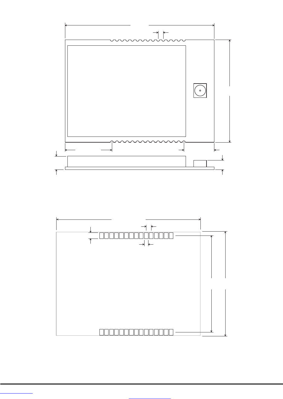
www.RFM.com Technical support +1.678.684.2000 Page 81 of 86
©2010 by RF Monolithics, Inc. E-mail: tech_sup@rfm.com DNT90 Integration Guide - 10/25/10
10.3 DNT90 Mechanical Specifications
1 . 4 5 0
( 3 6 . 8 )
0 . 9 8 0
( 2 7 . 9 )
D N T 9 0 C O u t l i n e a n d M o u n t i n g D i m e n s i o n s
0 . 0 5 0 ( 1 . 2 7 )
1
T o p V i e w
0 . 1 2 5
( 3 . 1 8 )
1 5
1 6 3 0
D i m e n s i o n s i n i n c h e s ( m m )
0 . 0 9 0
0 . 4 5 0 ( 1 1 . 4 ) 0 . 3 0 0 ( 7 . 6 2 )
Figure 10.3.1
0 . 0 6 0 ( 1 . 5 2 )
1 . 4 5 0 ( 3 6 . 8 )
0 . 9 8 0
( 2 4 . 9 )
D N T 9 0 C S o l d e r P a d D i m e n s i o n s
0 . 0 5 0 ( 1 . 2 7 )
1
T o p V i e w
1 5
1 6 3 0
D i m e n s i o n s i n i n c h e s ( m m )
0 . 0 3 5 ( 0 . 8 9 )
1 . 0 4 0
( 2 6 . 4 )
Figure 10.3.2
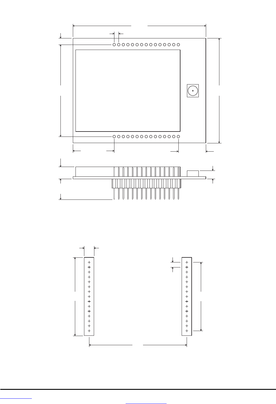
www.RFM.com Technical support +1.678.684.2000 Page 82 of 86
©2010 by RF Monolithics, Inc. E-mail: tech_sup@rfm.com DNT90 Integration Guide - 10/25/10
0 . 0 6 0
( 1 . 5 2 )
1 . 4 5 0
( 3 6 . 8 )
1 . 1 0 0
( 2 7 . 9 )
D N T 9 0 P O u t l i n e a n d M o u n t i n g D i m e n s i o n s
0 . 0 5 0 ( 1 . 2 7 )
1
T o p V i e w
0 . 1 2 5
( 3 . 1 8 )
1 5
1 6 3 0
D i m e n s i o n s i n i n c h e s ( m m )
0 . 4 5 0 ( 1 1 . 4 )
0 . 0 9 0
( 2 . 2 9 )
0 . 2 2 5
( 5 . 7 2 )
0 . 9 8 0
( 2 4 . 9 )
0 . 3 0 0 ( 7 . 6 2 )
Figure 10.3.3
0.980
( 2 4 . 9 )
0.050
( 1 . 2 7 )
0.700
( 1 7 . 8 )
0.100
( 2 . 5 4 )
0.800
( 2 0 . 3 )
D N T 9 0 P I n t e r f a c e C o n n e c t o r
P C B L a y o u t D e t a i l
C o n n e c t o r s a r e S A M T E C
S L M - 1 1 5 - 0 1 - G - S
o r E q u i v a l e n t
D i m e n s i o n s a r e i n i n c h e s ( m m )
Figure 10.3.4
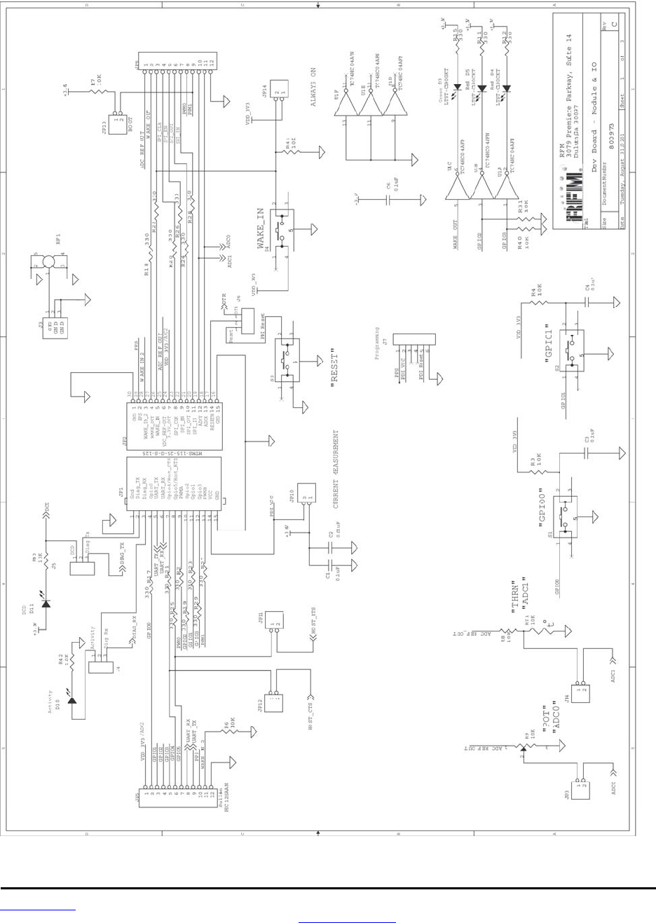
www.RFM.com Technical support +1.678.684.2000 Page 83 of 86
©2010 by RF Monolithics, Inc. E-mail: tech_sup@rfm.com DNT90 Integration Guide - 10/25/10
10.4 DNT90 Development Board Schematic
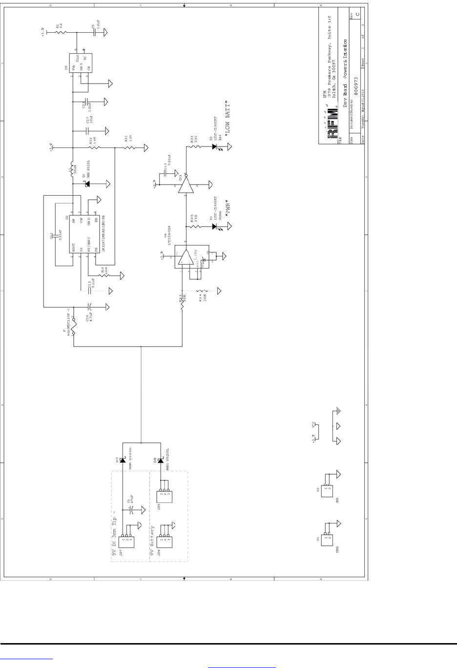
www.RFM.com Technical support +1.678.684.2000 Page 84 of 86
©2010 by RF Monolithics, Inc. E-mail: tech_sup@rfm.com DNT90 Integration Guide - 10/25/10
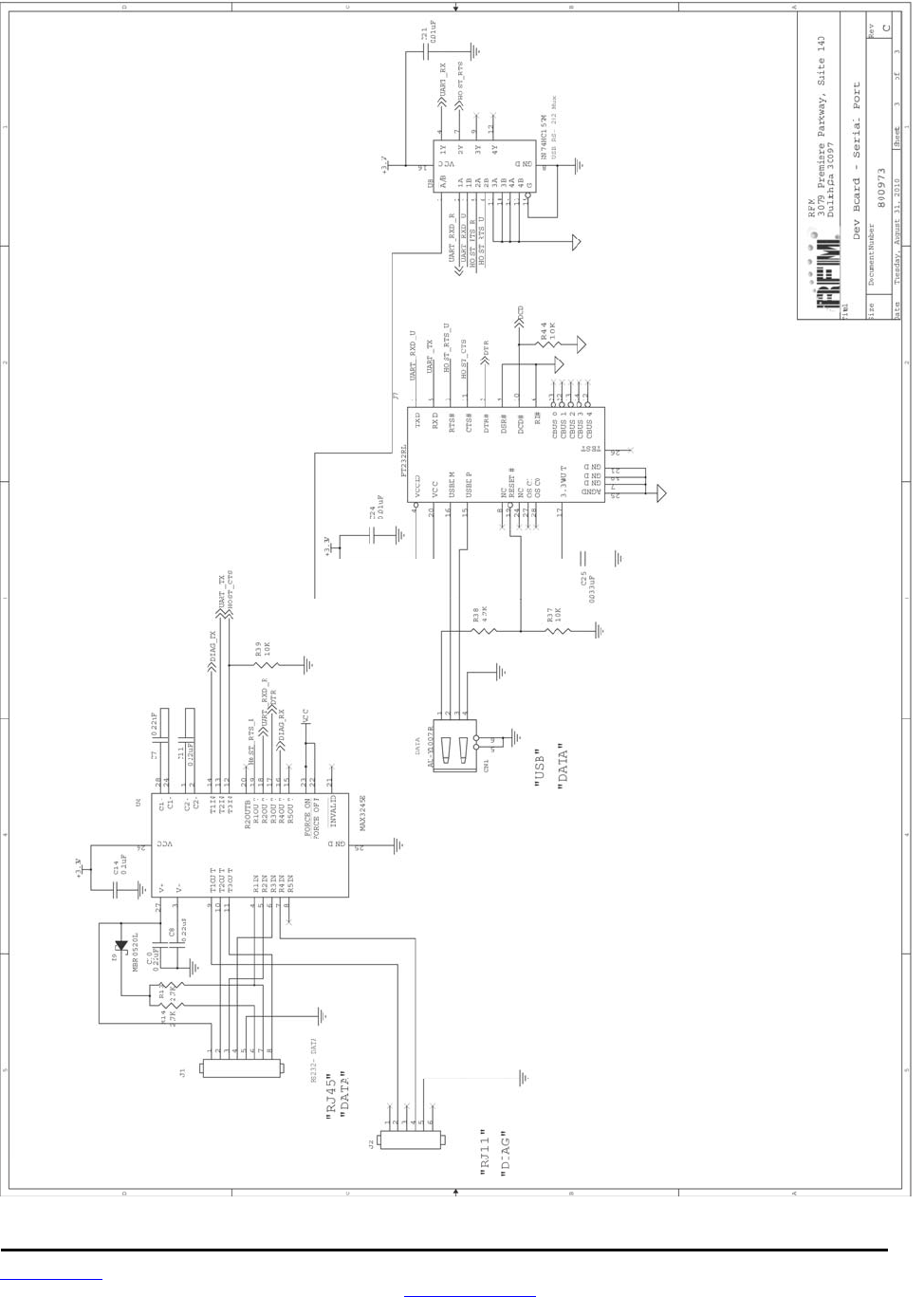
www.RFM.com Technical support +1.678.684.2000 Page 85 of 86
©2010 by RF Monolithics, Inc. E-mail: tech_sup@rfm.com DNT90 Integration Guide - 10/25/10

www.RFM.com Technical support +1.678.684.2000 Page 86 of 86
©2010 by RF Monolithics, Inc. E-mail: tech_sup@rfm.com DNT90 Integration Guide - 10/25/10
11.0 Warranty
Seller warrants solely to Buyer that the goods delivered hereunder shall be free from defects in materials
and workmanship, when given normal, proper and intended usage, for twelve (12) months from the date
of delivery to Buyer. Seller agrees to repair or replace at its option and without cost to Buyer all defective
goods sold hereunder, provided that Buyer has given Seller written notice of such warranty claim within
such warranty period. All goods returned to Seller for repair or replacement must be sent freight prepaid
to Seller’s plant, provided that Buyer first obtain from Seller a Return Goods Authorization before any
such return. Seller shall have no obligation to make repairs or replacements which are required by normal
wear and tear, or which result, in whole or in part, from catastrophe, fault or negligence of Buyer, or from
improper or unauthorized use of the goods, or use of the goods in a manner for which they are not de-
signed, or by causes external to the goods such as, but not limited to, power failure. No suit or action
shall be brought against Seller more than twelve (12) months after the related cause of action has oc-
curred. Buyer has not relied and shall not rely on any oral representation regarding the goods sold he-
reunder, and any oral representation shall not bind Seller and shall not be a part of any warranty.
THE PROVISIONS OF THE FOREGOING WARRANTY ARE IN LIEU OF ANY OTHER WARRANTY,
WHETHER EXPRESS OR IMPLIED, WRITTEN OR ORAL (INCLUDING ANY WARRANTY OR MER-
CHANT ABILITY OR FITNESS FOR A PARTICULAR PURPOSE). SELLER’S LIABILITY ARISING
OUT OF THE MANUFACTURE, SALE OR SUPPLYING OF THE GOODS OR THEIR USE OR DISPO-
SITION, WHETHER BASED UPON WARRANTY, CONTRACT, TORT OR OTHERWISE, SHALL NOT
EXCEED THE ACTUAL PURCHASE PRICE PAID BY BUYER FOR THE GOODS. IN NO EVENT
SHALL SELLER BE LIABLE TO BUYER OR ANY OTHER PERSON OR ENTITY FOR SPECIAL, IN-
CIDENTAL OR CONSEQUENTIAL DAMAGES, INCLUDING, BUT NOT LIMITED TO, LOSS OF PROF-
ITS, LOSS OF DATA OR LOSS OF USE DAMAGES ARISING OUT OF THE MANUFACTURE, SALE
OR SUPPLYING OF THE GOODS. THE FOREGOING WARRANTY EXTENDS TO BUYER ONLY AND
SHALL NOT BE APPLICABLE TO ANY OTHER PERSON OR ENTITY INCLUDING, WITHOUT LIMI-
TATION, CUSTOMERS OF BUYERS.
Part # M-0090-0002, Rev A