Murata Electronics North America DNT90 Spread Spectrum Wireless Transceiver User Manual manual pt b
Murata Electronics North America Spread Spectrum Wireless Transceiver manual pt b
Contents
- 1. Manual
- 2. manual pt a
- 3. manual pt b
manual pt b

Preliminary
www.RFM.com Technical support +1.678.684.2000 Page 41 of 80
© 2010-2012 by RF Monolithics, Inc. E-mail: tech_sup@rfm.com DNT90 Integration Guide - 05/10/12
7.4 Configuration Parameter Registers
The configuration parameters in a DNT90 module are stored in a set of variable length registers. Most
registers are read-write, with a few read-only or write-only. Changes made to the register settings are
temporary until a MemorySave command is executed. Resetting or power-cycling the module will clear
any changes that have not been saved to permanent memory using the MemorySave command. DNT90
modules can be configured to start in protocol mode at power-up, in which case the EnterProtocolMode
command is not required.
7.4.1 Bank 0x00 - Transceiver Setup
Bank Location Name R/W Size Range Default
0x00 0x00 DeviceMode R/W 0x01 0..2 0 (remote)
0x00 0x01 HopDuration R/W 0x01 16..200 40 (20 ms)
0x00 0x02 ParentNwkID R/W 0x01 0..63, 255 255 (any parent)
0x00 0x03 SecurityKey R/W 0x10 0..2^128-1 0
0x00 0x13 SleepModeEn R/W 0x01 0..2 0 (off)
0x00 0x14 WakeResponseTime R/W 0x02 0..30000 500 (500 ms)
0x00 0x16 WakeLinkTimeout R/W 0x01 0..255 5 (5 s)
0x00 0x17 AltParentNwkID R/W 0x01 0..63, 255 255 (disabled)
0x00 0x18 TxPower R/W 0x01 0..1 1 (+22 dBm)
0x00 0x19 UserTag R/W 0x10 string “DNT90”
0x00 0x29 RmtTransDestAddr R/W 0x03 0x000000 (Base)
0x00 0x2C Store&ForwardEn R/W 0x01 0..1 0 (disabled)
0x00 0x2D BaseModeNetID R/W 0x01 1..63, 255 255
0x00 0x2E HeartbeatIntrvl R/W 0x02 0..65535 20 (seconds)
0x00 0x30 SystemId R/W 0x01 0..255 0
0x00 0x31 EndToEndAckEnable R/W 0x01 0..1 0 (disabled)
0x00 0x32 LinkRetryInterval R/W 0x02 0..65535 0 (disabled)
0x00 0x34 FastBeaconCount R/W 0x02 0..65535 0 (off)
0x00 0x36 FastBeaconTrig R/W 0x01 0..255 0 (off)
Table 7.4.1.1
DeviceMode - this parameter selects the operating mode for the radio:
0x00 = remote (default)
0x01 = base
0x02 = router (store and forward system)
Note that changing this setting does not take effect immediately. It must be followed by a MemorySave
command and then either a hardware reset or a power off/on cycle. A router without a valid BaseMode-
NetID operates as a remote.
HopDuration - this parameter sets the duration of the hop frame, and can only be set on the base. The
duration is an 8-bit value, 0.5 ms/count. The valid range is from 8 to 100 ms. Changing the hop duration
on the base must be followed by a MemorySave command to allow the change to persist through a reset
or power cycle. A HopDuration change takes effect immediately. Child radios will re-link following a
HopDuration parameter change as they receive the updated hop duration value from the base.

Preliminary
www.RFM.com Technical support +1.678.684.2000 Page 42 of 80
© 2010-2012 by RF Monolithics, Inc. E-mail: tech_sup@rfm.com DNT90 Integration Guide - 05/10/12
ParentNwkID - this parameter specifies the parent (BaseModeNetID) that a child radio is allowed to join.
The valid range of this parameter is 0 to 63 (0x00 to 0x3F), plus 255 (0xFF). Setting the ParentNwkID to
255 allows connection to any parent. This parameter is applicable only to remotes and routers. Also see
the discussion of AltParentNwkID below.
Security Key - this 16-byte parameter sets the 128-bit AES encryption key. To protect the key, it is a write-
only parameter for the user. It always reads back as 0x2A.
SleepModeEn - this parameter enables/disables sleep mode (remotes only). Sleep mode is used in con-
junction with the automatic I/O reporting feature to wake up a remote on specific triggers. The default val-
ue for this parameter is 0 (off). Setting this parameter to 1 invokes sleep mode immediately. Setting this
parameter to 2 invokes sleep mode following reset, allowing this and other parameter updates to be
stored before sleep mode is invoked.
WakeResponseTime - this parameter set how long sleep is deferred in a DNT90 remote configured for
sleep mode after:
link acquisition
receiving an ACK from the device’s parent
receiving a packet that requires processing by the device
after receiving a protocol packet from the device’s local host.
WakeLinkTimeout - this parameter sets the maximum length of time that a remote in sleep mode will
spend trying to acquire a link to its parent before going back to sleep, from a minimum of 1 to 255 se-
conds in 1 second steps. If this value is set to 0, the remote will stay awake and continue trying to link to
its base indefinitely.
AltParentNwkID - this parameter specifies an alternate parent (BaseModeNetID) that a child radio is
allowed to join. This parameter is used to provide more robust message routing when setting the Parent-
NwkID to its 0xFF wildcard value is not appropriate. The valid range of this parameter is 0x00 to 0x3F,
plus 0xFF. Rather than specifying wildcard operation, setting the AltParentNwkID to 0xFF disables the
selection of an alternate parent. This parameter is applicable only to remotes and routers.
TxPower - this parameter sets the transmit power level (default is 0x01):
0x00 = +16 dBm or 40 mW
0x01 = +22 dBm or 158 mW
UserTag - this parameter is a user definable field intended for use as a location description or other iden-
tifying tag such as a “friendly name”.
RmtTransDestAddr - this parameter holds the default destination for transparent mode data packets and
event packets. This parameter defaults to the base station’s address (0x000000) except on a base sta-
tion, where at startup it will be changed to the broadcast address (0xFFFFFF) if the firmware detects that
it is set to 0x000000. Note - if a module’s configuration is changed from a base to a remote or router, this
parameter must be set back to 0x000000 or the module will send broadcast packets in transparent mode
or for event packets.
Store&ForwardEn - setting this parameter to 0x01 enables store-and-forward system operation. Store-
and-forward operation is disabled by default.
BaseModeNetID - applicable to the base and routers only, this parameter specifies the network ID of a
device’s own network when acting as parent. A child is allowed to join a network when its ParentNwkID

Preliminary
www.RFM.com Technical support +1.678.684.2000 Page 43 of 80
© 2010-2012 by RF Monolithics, Inc. E-mail: tech_sup@rfm.com DNT90 Integration Guide - 05/10/12
parameter matches a parent’s BaseModeNetID. The valid range of this parameter is 0x00 to 0x3F. A val-
ue greater than 0x3F is invalid and will be forced to 0x00 on a base. A router with an invalid Base-
ModeNetID will be forced to operate as a remote.
HeartbeatInterval - When set to 0, all heartbeats are disabled, including the initial heartbeat issued after
link acquisition. When set to 0xFFFF (default), periodic heartbeats are disabled but the initial linkup
heartbeat is enabled. The periodic heartbeat interval is scaled 1 second/count, and applies to DNT90s
where sleep mode is disabled. Remotes with sleep mode enabled must have periodic reports and/or ADC
sampling enabled for heartbeats to be generated.
SystemId - this parameter holds the ID for a DTN90 system. DNT90 systems that may physically overlap
must have different system IDs.
EndToEndAckEnable - when this parameter is set to 1 and the DNT90 is in protocol mode, the originator
will indicate in its transmitted packet that an ACK is expected from the packet’s destination node. Setting
this parameter to 0x00 reduces network congestion in a store-and-forward system, but no TxDataReply
will be sent from the destination to confirm reception.
LinkRetryInterval - when a remote enters sleep mode with an unsent packet in its queue, the remote will
wake up after the number of seconds held in this parameter and try to link so that pending packets can be
transmitted. When this parameter is set to 0, this feature is disabled.
FastBeaconCount - this parameter controls the fast beacon mode, which is used to speed up network
synchronization. Fast beacon mode is especially useful for multi-level store-and-forward networks that are
configured with long hop durations. Fast beacon mode is controlled by the base station. If the Fast-
BeaconCount parameter is set to a non-zero value, when the base is reset, powered up or the Fast-
BeaconTrig parameter is set to a non-zero value, it will output the number of 6 ms beacons specified in
the FastBeaconCount parameter. The base and all of its children will synchronously decrement a version
of the parameter in their beacons, such that it will reach 0 simultaneously on all devices. This allows all
nodes in the DNT90 system to simultaneously transition to using the configured base slot size and num-
ber of slots. The beacons also inform all child devices that the network is in Fast beacon mode, so that all
children will observe the FastBeaconCount and assume, in addition to the 6ms hop timing, a base slot
size of 0 and a number of slots equal to 1. If the cycled base station operating parameters transmitted in
the beacons, including the BaseSlotSize and NumSlots (see Bank 0x01 parameters) are stable, then a
further speedup of synchronization can be achieved by setting the NumBaseParms on the base station to
8. However, this should be done only after all child devices are known to have configuration parameters
identical to the base station’s saved in their EEPROM. The first 9 parameters contain the AES counter
and MAC address that are needed to synchronize encryption, along with NumBaseParms.
FastBeaconTrig - when this parameter is set to any non-zero value on a base station, fast beacon mode
starts if the fastBeaconCount register is already set to a non-zero value. It auto-clears on a base station
and will read back as 0 after it is cleared. On a router or remote, it would do nothing and will not clear
except after reset.

Preliminary
www.RFM.com Technical support +1.678.684.2000 Page 44 of 80
© 2010-2012 by RF Monolithics, Inc. E-mail: tech_sup@rfm.com DNT90 Integration Guide - 05/10/12
7.4.2 Bank 0x01 - System Settings
Bank 1 holds configuration parameters to be input to the base only. The base passes these parameters to
the routers and remotes as needed. The exception is InitFrequencyBand parameter which can also be set
in routers and remotes.
Bank Location Name R/W Size Range Default
0x01 0x00 InitFrequencyBand R/W 0x01 0..3, 255 0 (US)
0x01 0x01 NumSlots R/W 0x01 1..8 3
0x01 0x02 BaseSlotSize R/W 0x01 6..105 40
0x01 0x03 SlotLease R/W 0x01 1..255 2 (hops)
0x01 0x04 BcstAttemptLimit R/W 0x01 0..254 1
0x01 0x05 ArqAttemptLimit R/W 0x01 1..255 6
0x01 0x06 LinkDropThreshold R/W 0x01 1..255 10 (hops)
0x01 0x07 P2PReplyTimeout R/W 0x01 0..255 100 (hops)
0x01 0x08 RegistryTimeout R/W 0x01 0..255 50 (hops)
0x01 0x09 NumBaseParms R/W 0x01 8..21 21
Table 7.4.2.1
InitFrequencyBand - this parameter sets the range of frequencies and channel spacing over which the
DNT90 system will initially operate. Four bands are available:
0x00 Band 0: 902.76 to 927.24 MHz, 52 channels, 480 kHz spacing
0x01 Band 1: 902.76 to 926.76 MHz, 26 channels, 960 kHz spacing
0x02 Band 2: 915.72 to 927.74 MHz, 25 channels, 480 kHz spacing
0x03 Band 3: 902.76 to 914.76 MHz, 26 channels, 480 kHz spacing
0xFF wildcard - will accept any band
Bands 0, 1, 2 and 3 can be used in North and South America (902 to 928 MHz band), with Band 2 usable
in Australia.
NumSlots - this parameter sets the number of slots available for child transmissions following the parent’s
beacon transmission on a hop.
BaseSlotSize - this parameter set the maximum number of payload bytes that the base can send on a
single hop. The default value is 40 bytes.
SlotLease - this parameter set the number of hops a parent radio will reserve a slot for a child after re-
ceiving a message from that child. Small values such as 2 are suited to short data bursts, and larger val-
ues are generally a better choice when devices send a stream of non-continuous data across consecutive
hops. The minimum value is 1, assuring that a child can receive an ACK on the next hop after it transmits.
BcstAttemptLimit - setting this parameter to 0 enables automatic broadcast message repeats based on
the ArqAttemptLimit parameter value. Setting this parameter to a value between 1 and 254 specifies the
number of broadcast message repeats independent of the ArqAttemptLimit. This parameter should not be
set to 0 if ArqAttemptLimit is set to 255.
ArqAttemptLimit - this sets the maximum number of attempts that will be made to send a message on the
RF link. Setting this parameter to the maximum value of 255 is a flag value indicating that there should be
no limit to the number of attempts to send each packet (infinite number of attempts). This mode is intend-
ed for point-to-point networks in serial data cable replacement applications where absolutely no packets

Preliminary
www.RFM.com Technical support +1.678.684.2000 Page 45 of 80
© 2010-2012 by RF Monolithics, Inc. E-mail: tech_sup@rfm.com DNT90 Integration Guide - 05/10/12
can be lost. Note - if this mode is used in a multipoint network, one remote that has lost link will shut down
the entire network if the base is trying to send it data.
LinkDropThreshold - this is the number of consecutive beacons missed by a remote that causes the re-
mote to restart a link acquisition search. Please contact RFM technical support before making changes to
the parameter.
P2PReplyTimeout - this parameter sets the reply timeout for peer-to-peer messages sent from one node
to another. Because each leg of the journey from one node to another and back may take multiple trans-
mit attempts, the length of time to confirm receipt and issue a TxDataReply is subject to more variation
than a transmission directly between a base and a remote. When AckEnable is selected, the P2PReply-
Timeout parameter specifies the maximum number of hops or hop pairs that a remote will wait for a reply
from its recipient. If a reply returns sooner than the timeout, the remote will send a TxDataReply indicating
success (ACK) to its host as soon as it is received, and cancels the timeout. If a reply does not come
back before the timeout expires, the remote will send a TxDataReply to its host indicating failure (NAK). If
a reply should come back after the timeout expires the remote will ignore it, as a TxDataReply has al-
ready been sent. The units of this parameter are in hops for point-to-point and point-to-multipoint opera-
tion and in hop pairs for store-and-forward operation.
RegistryTimeout - this parameter sets the number of hops without contact from a child device for which a
parent device will preserve the Transaction ID (TID) history for that child. The TID is used to filter out du-
plicate packets. After a registry timeout occurs, the TID history is discarded.
NumBaseParms - this parameter controls the number of cycled parameters sent in the base station bea-
con. It must be left in its default value of 21 until all nodes in a DNT90 system have received all cycled
parameters and stored them locally in EEPROM. At this point the number of cycled parameters can be
set to 9, which will significantly speed up future system resynchronizations.
7.4.3 Bank 0x02 - Status Parameters
Bank Location Name R/W Size Range Default
0x02 0x00 MacAddress R 0x03 0..0xFFFFFF Fixed value
0x02 0x03 CurrNwkID R 0x01 0..63, 255 Current Value
0x02 0x04 CurrFreqBand R 0x01 0..2, 255 Current Value
0x02 0x05 LinkStatus R 0x01 0..5 Current status
0x02 0x06 RemoteSlotSize R 0x01 0..109 Current Value
0x02 0x07 SlotNumber R 0x01 0..7 Current Value
0x02 0x08 HardwareVersion R 0x01 0x41..0x5A 0x43 = Rev “C”
0x02 0x09 FirmwareVersion R 0x01 0x00..0xFF Current FW load
0x02 0x0A FirmwareBuildNum R 0x02 0..65535 Current FW load
0x02 0x0C FirmwareBuildDate R 0x03 BCD (“YYMMDD”) Current FW load
0x02 0x0F FirmwareBuildTime R 0x03 BCD (“HHMMSS”) Current FW load
0x02 0x12 RssiIdle R 0x01 -128..127 Current Value
0x02 0x13 RssiLast R 0x01 -128..127 Current Value
0x02 0x14 AvgBeaconPower R 0x01 -128..127 Current Value
0x02 0x15 ParentMacAddress R 0x03 0..0xFFFFFF Current Value
0x02 0x18 ModelNumber R 1 0x90 indicates DNT90
Table 7.4.3.1

Preliminary
www.RFM.com Technical support +1.678.684.2000 Page 46 of 80
© 2010-2012 by RF Monolithics, Inc. E-mail: tech_sup@rfm.com DNT90 Integration Guide - 05/10/12
MacAddress - this parameter holds the radio's unique 24-bit MAC address.
CurrNwkID - this parameter holds the ID of the network the radio is currently assigned to or connected to.
A value of 255 (0xFF) means the radio has powered up and is scanning for a network but has not yet
joined one.
CurrFreqBand - this parameter holds the frequency band of the network that the radio is currently as-
signed to or connected to. A value of 0xFF means the radio has powered up and is scanning for a net-
work but has not yet joined one.
LinkStatus - this parameter holds the link status of a router or remote:
0x00 = idle
0x01 = lost link
0x02 = acquiring link
0x03 = collecting parameters from the base
0x04 = registering
0x05 = registered
RemoteSlotSize - this parameter holds the current remote slot size, defined as the maximum number of
message bytes a remote can send on a single hop. The RemoteSlotSize is calculated by each radio in a
system based on the values of the HopDuration, BaseSlotSize, and NumSlots parameters.
SlotNumber - this parameter holds the current slot number assigned to a router or remote.
HarwareVersion - this parameter holds an identifier indicating the hardware revision (ASCII character). A
value of 0x43 is defined for the DNT90 Revision C hardware.
FirmwareVersion - this parameter holds the firmware version of the radio in 2-digit BCD format.
FirmwareBuildNum - this parameter holds the firmware build number, in binary format.
FirmwareBuildDate - this parameter holds the date of firmware build in MM/DD/YY format.
FirmwareBuildTime - this parameter holds the time of the firmware build in HH:MM:SS format.
RssiIdle - this 2’s compliment parameter holds the last RSSI measurement in dBm made during a time
when the RF channel was idle. This parameter is useful for detecting interferers.
RssiLast - this 2’s compliment parameter holds the last RSSI measurement in dBm made during the re-
ceipt of an RF packet with a valid CRC. This parameter is useful for network commissioning/diagnostics.
AvgBeaconPower - this 2’s compliment parameter holds the alpha-filtered beacon power (dBm) received
from a device’s parent, where alpha = 0.0625.
ParentMacAddress - this parameter holds the MAC address of a DNT90’s parent.
ModelNumber - this parameter specifies the DNT model, in this case a DNT90.

Preliminary
www.RFM.com Technical support +1.678.684.2000 Page 47 of 80
© 2010-2012 by RF Monolithics, Inc. E-mail: tech_sup@rfm.com DNT90 Integration Guide - 05/10/12
7.4.4 Bank 0x03 - Serial and SPI Settings
Bank Location Name R/W Size Range Default
0x03 0x00 SerialRate R/W 0x01 0..10 3 (9600 baud)
0x03 0x01 SerialParams R/W 0x01 0..7 0 (8-N-1)
0x03 0x02 SpiMode R/W 0x01 0..2 0 (SPI disabled)
0x03 0x03 SpiRateSel R/W 0x01 0..2 0 (125 kHz)
0x03 0x04 SpiOptions R/W 0x01 0..7 0
0x03 0x05 SpiMasterCmdLen R/W 0x01 0..16 0
0x03 0x06 SpiMasterCmdStr R/W 0x10 0..16 byte string All 0x00 bytes
Table 7.4.4.1
SerialRate - this parameter sets the serial data rate as shown below:
Setting Serial rate
0x00 1.2 kbps
0x01 2.4 kbps
0x02 4.8 kbps
0x03 9.6 kbps
0x04 14.4 kbps
0x05 19.2 kbps
0x06 28.8 kbps
0x07 38.4 kbps
0x08 57.6 kbps
0x09 115.2 kbps
0x0A 230.4 kbps
0x0B 250.0 kbps
SerialParams - this parameter sets the serial mode options for parity and stop bits:
Setting Mode
0x00 No parity, 8 data bits, 1 stop bit (default)
0x01 No parity, 8 data bits, 2 stop bits
0x02 Reserved
0x03 Reserved
0x04 Even parity, 8 data bits, 1 stop bit
0x05 Even parity, 8 data bits, 2 stop bits
0x06 Odd parity, 8 data bits, 1 stop bit
0x07 Odd parity, 8 data bits, 2 stop bits
Note that 8-bit data with no parity is capable of carrying 7-bit data with parity for compatibility without loss
of generality for legacy applications that may require it.
SpiMode - this parameter sets the SPI operating mode:
Setting Mode
0x00 SPI disabled - serial UART mode (default)
0x01 SPI Slave mode
0x02 SPI Master mode
SpiRateSel - this parameter sets the SPI master mode clock rate:
Setting Mode
0x00 125 kbps
0x01 250 kbps
0x02 500 kbps

Preliminary
www.RFM.com Technical support +1.678.684.2000 Page 48 of 80
© 2010-2012 by RF Monolithics, Inc. E-mail: tech_sup@rfm.com DNT90 Integration Guide - 05/10/12
SpiOptions - this parameter allows the SPI to be configured with the following options:
Setting Option
0x00 Leading edge rising, sample leading edge, MSBs sent first
0x01 Leading edge rising, sample falling edge, MSBs sent first
0x02 Leading edge falling, sample leading edge, MSBs sent first
0x03 Leading edge falling, sample falling edge, MSBs sent first
0x04 Leading edge rising, sample leading edge, LSBs sent first
0x05 Leading edge rising, sample falling edge, LSBs sent first
0x06 Leading edge falling, sample leading edge, LSBs sent first
0x07 Leading edge falling, sample falling edge, LSBs sent first
SpiMasterCmdLen - this parameter sets the length for the SPI master command string that will be used to
interrogate the slave peripheral, when SPI master mode is selected with periodic I/O reporting enabled.
SpiMasterCmdStr - this parameter holds the SPI master command string that is used to interrogate the
slave peripheral when SPI master mode is selected and periodic I/O reporting is enabled.
7.4.5 Bank 0x04 - Host Protocol Settings
Bank Location Name R/W Size Range Default
0x04 0x00 ProtocolMode R/W 0x01 0..1 0 (Transparent)
0x04 0x01 TxTimeout R/W 0x01 0..255 0 (No timeout)
0x04 0x02 MinPacketLength R/W 0x01 0..255 1 (byte)
0x04 0x03 TransPtToPtMode R/W 0x01 0..1 1 (Last RX)
0x04 0x04 MsgsPerHop R/W 0x01 1..8 8
Table 7.4.5.1
ProtocolMode - this parameter selects the host protocol mode. The default is 0x00, which is transparent
mode, meaning the radio conveys whatever characters that are sent to it transparently, without requiring
the host to understand or conform to the DNT90's built-in protocol. This setting is recommended for point-
to-point applications for legacy applications such as wire replacements where another serial protocol may
already exist. Setting this parameter to 0x01 enables the DNT90 protocol formatting. It is not necessary to
define the same protocol mode for all radios in a network. For example, it is frequently useful to configure
all the remotes for transparent mode and the base for protocol mode. Note that it is possible for the host
to switch the radio from transparent mode to protocol mode and back as required by transmitting an
EnterProtocolMode command.
TxTimeout - this parameter is used to group transparent data to be sent in a single transmission rather
than being split over two hops. Messages sent over two hops can have gaps in the received data stream
that can cause problems for the receiving application - for example, Modbus RTU. This parameter is the
transmit timeout used for determining message boundaries in transparent data mode. Parameter units
are in milliseconds. A message boundary is determined whenever a gap between consecutive characters
is equal to or greater than the TxTimeout value, or the number of bytes reaches the MinPacketLength.
Either condition will trigger a transmission. The default TxTimeout value is 0 ms which will have the radio
send whatever data is in its transmit buffer as soon as possible.
MinPacketLength - this parameter is similar to TxTimeout except it uses the number of bytes received
instead of the amount of time without receiving a byte. The default is one byte. A transmission is triggered
when either the number of bytes reaches MinPacketLength or a gap is detected between consecutive

Preliminary
www.RFM.com Technical support +1.678.684.2000 Page 49 of 80
© 2010-2012 by RF Monolithics, Inc. E-mail: tech_sup@rfm.com DNT90 Integration Guide - 05/10/12
characters greater than TxTimeout. If this parameter is set larger than the applicable slot size, the slot
size overrides this parameter and a transmission is triggered when the slot size is filled.
TransPtToPtMode - when this parameter is set to 0x00, the destination address of transparent mode
packets will be the configured RemoteDestAddr. When set to 0x01, the address initializes to Remote-
DestAddr and then updates to the most recent RX packet processed.
MsgsPerHop - this parameter sets the maximum number of messages a DNT90 can send in each hop
frame. The default value is 8 messages, which is suitable for most applications. Setting MsgsPerHop to a
low value allows message flow rate to be controlled.
7.4.6 Bank 0x05 - I/O Parameters
Bank Location Name R/W Size Range In Bits Default
0x05 0x00 All-IO R/W 0x0D 104 N/A
0x05 0x0D Gpio0 R/W 0x01 1 0
0x05 0x0E Gpio1 R/W 0x01 1 0
0x05 0x0F Gpio2 R/W 0x01 1 0
0x05 0x10 Gpio3 R/W 0x01 1 0
0x05 0x11 Gpio4 R/W 0x01 1 0
0x05 0x12 Gpio5 R/W 0x01 1 0
0x05 0x13 Adc0 R 0x02 12 N/A
0x05 0x15 Adc1 R 0x02 12 N/A
0x05 0x17 Adc2 R 0x02 12 N/A
0x05 0x19 EventFlags R/W 0x02 16 N/A
0x05 0x1B Dac0 R/W 0x02 12 0
0x05 0x1D Dac1 R/W 0x02 12 0
Table 7.4.6.1
All-IO - this 13-byte parameter packs all the following parameters into a single value. Note that the infor-
mation in parameters GPIO0 through GPIO5 is compressed into a single byte to save space in the All-IO
parameter. When the ADC is operating in differential mode, the ADC1 to ADC0 differential reading is
stored in the ADC0 position, and the ADC2 to ADC0 differential reading is stored in the ADC1 position.
The ADC2 reading is not used in ADC differential mode and this position is set to 0.
Gpio0 through Gpio5 - if a pin is configured as an output, writing to its corresponding parameter to sets
the pin’s logic state. If a pin is configured as an input, writing to its corresponding parameter enables or
disables the pin’s internal pull-up. Reading these registers returns the current level detected on the corre-
sponding pins.
Adc0 through Adc2 - read-only parameters that return the current reading for the selected ADC channel
(Little-Endian byte order). When the ADC is operating in differential mode, the ADC1 to ADC0 differential
reading is stored in the ADC0 position, and the ADC2 to ADC0 differential reading is stored in the ADC1
position. The ADC2 reading is not used in ADC differential mode and this position is set to 0. Also, see
the discussion of the AdcSampleIntvl parameter below.
EventFlags - used with the automatic I/O reporting feature, this parameter indicates which I/O events
have been triggered since the last report (write 0x0000 to reset):

Preliminary
www.RFM.com Technical support +1.678.684.2000 Page 50 of 80
© 2010-2012 by RF Monolithics, Inc. E-mail: tech_sup@rfm.com DNT90 Integration Guide - 05/10/12
bits 15..8 Reserved
bit 7 ADC2 high/low threshold excursion
bit 6 ADC1 high/low threshold excursion
bit 5 ADC0 high/low threshold excursion
bit 4 Periodic timer report
bit 2 GPIO2 edge transition
bit 1 GPIO1 edge transition
bit 0 GPIO0 edge transition
Dac0 through Dac1 - sets the DAC outputs. The range of this parameter is 0x0000 to 0x0FFF.
7.4.7 Bank 0x06 - I/O Settings
Bank Location Name R/W Size Range In Bits Default
0x06 0x00 GpioDir R/W 0x01 6 0x00 (All inputs)
0x06 0x01 GpioInit R/W 0x01 6 0x00 (All zeros)
0x06 0x02 GpioAlt R/W 0x01 6 0x00
0x06 0x03 GpioEdgeTrigger R/W 0x01 8 0x01
0x06 0x04 GpioSleepMode R/W 0x01 6 0x00 (Off)
0x06 0x05 GpioSleepDir R/W 0x01 6 0x00 (All inputs)
0x06 0x06 GpioSleepState R/W 0x01 6 0x00 (All zero)
0x06 0x07 Dac0Init R/W 0x02 12 0x0000
0x06 0x09 Dac1Init R/W 0x02 12 0x0000
0x06 0x0B AdcSampleIntvl R/W 0x04 32 0x0A (100 ms)
0x06 0x0F Adc0ThresholdLo R/W 0x02 12 0xF800
0x06 0x11 Adc0ThresholdHi R/W 0x02 12 0x07FF
0x06 0x13 Adc1ThresholdLo R/W 0x02 12 0xF800
0x06 0x15 Adc1ThresholdHi R/W 0x02 12 0x07FF
0x06 0x17 Adc2ThresholdLo R/W 0x02 12 0xF800
0x06 0x19 Adc2ThresholdHi R/W 0x02 12 0x07FF
0x06 0x1B IoReportTrigger R/W 0x01 8 0x01 (GPIO0)
0x06 0x1C IoReportInterval R/W 0x04 32 30000 (ms)
0x06 0x20 IoPreDelay R/W 0x01 8 8 (ms)
0x06 0x21 IoBindingEnable R/W 0x01 1 0 (Disabled)
0x06 0x22 DacReference R/W 0x01 2 0 (ADC_EXT_REF)
0x06 0x23 AdcReference R/W 0x01 2 0 (ADC_EXT_REF)
0x06 0x24 AdcAveSelect R/W 0x01 8 0x01
0x06 0x25 ExtAdcScaleFactor R/W 0x02 16 0x8000
0x06 0x27 ExtAdcOffset R/W 0x02 16 0x0000
0x06 0x29 ExtDacScaleFactor R/W 0x02 16 0x8000
0x06 0x2B ExtDacOffset R/W 0x02 16 0x0000
0x06 0x2D VccAdcScaleFactor R/W 0x02 16 0x8000
0x06 0x2F VccAdcOffset R/W 0x02 16 0x0000
0x06 0x31 VccDacScaleFactor R/W 0x02 16 0x8000
0x06 0x33 VccDacOffset R/W 0x02 16 0x0000
0x06 0x35 1VAdcScaleFactor R/W 0x02 16 0x8000
0x06 0x37 1VAdcOffset R/W 0x02 16 0x0000
0x06 0x39 1VDacScaleFactor R/W 0x02 16 0x8000
0x06 0x3B 1VDacOffset R/W 0x02 16 0x0000
0x06 0x3D AdcDiffMode R/W 0x01 8 0 (single-ended)
0x06 0x3E AdcGainCh0 R/W 0x01 8 0 (gain = 1)

Preliminary
www.RFM.com Technical support +1.678.684.2000 Page 51 of 80
© 2010-2012 by RF Monolithics, Inc. E-mail: tech_sup@rfm.com DNT90 Integration Guide - 05/10/12
Bank Location Name R/W Size Range In Bits Default
0x06 0x3F AdcGainCh1 R/W 0x01 8 0 (gain = 1)
0x06 0x40 AdcDiffScaleFactorCh0 R/W 0x02 16 0x8000
0x06 0x42 AdcDiffOffsetCh0 R/W 0x02 16 0x0000
0x06 0x44 AdcDiffScaleFactorCh1 R/W 0x02 16 0x8000
0x06 0x46 AdcDiffOffsetCh1 R/W 0x02 16 0x0000
0x06 0x47 FastAdcPrescaler R/W 0x01 1 byte, range 1..7 5 (128)
0x06 0x48 SlowAdcPresccaler R/W 0x01 1 byte, range 0..7 2 (16)
0x06 0x49 MaxQueuedEvents R/W 0x01 1 byte, range 0..20 8 (reports)
0x06 0x4A AdcSkipCount R/W 0x01 1 byte 0 (samples)
Table 7.4.7.1
GpioDir - this parameter is a bitmask that sets whether each GPIO is an input (0) or outputs (1). The de-
fault is all inputs.
GpioInit - this parameter is a bitmask that sets the initial value for any GPIOs which are enabled as out-
puts. For GPIOs enabled as inputs, this sets the initial pull-up setting.
GpioAlt - Specifies which GPIO pins will have their alternate functions enabled: Bit 2 - diversity toggle en-
able, Bit 3 - RS485 enable, Bit 4 - /HOST_CTS enable, Bit5 - /HOST_RTS enable.
Bit Alternate Function Default Bit Mask
0 (none) 0 0x01
1 (none) 0 0x02
2 Diversity Toggle 0 0x04
3 RS485 (N/A in SPI Slave mode) 0 0x08
4 /Host_CTS (N/A in SPI Slave mode) 1 0x10
5 /HOST_RTS (N/A in SPI Slave mode) 1 0x20
Table 7.4.7.2
GpioEdgeTrigger -This parameter consists of a set of four 2-bit fields that define when GPIO triggers are
enabled for I/O event reporting:
bits 7..6 GPIO3 edge function
bits 5..4 GPIO2 edge function
bits 3..2 GPIO1 edge function
bits 1..0 GPIO0 edge function
The bit values for each GPIO map to the following settings:
Value GPIO edge behavior
11 Rising edge trigger, neither level keeps remote awake
10 Bidirectional edge trigger, neither level keeps remote awake
01 Rising edge trigger, holding high keeps remote awake
00 Falling edge trigger, holding low keeps remote awake
Table 7.4.7.3
GpioSleepMode - this parameter is a bitmask that enables configuring the I/O direction and state of
GPIO0..GPIO5 when the module is sleeping. Bits 0..5 correspond to GPIO0..GPIO5. Setting a Gpio-
SleepMode bit to 1 enables sleep mode configuration of the corresponding GPIO. Setting a GpioSleep-
Mode bit to 0 causes the corresponding GPIO to remain configured as in active mode. Note that when the

Preliminary
www.RFM.com Technical support +1.678.684.2000 Page 52 of 80
© 2010-2012 by RF Monolithics, Inc. E-mail: tech_sup@rfm.com DNT90 Integration Guide - 05/10/12
GpioAlt bit is set for GPIO4, the corresponding GpioSleepMode bit is ignored and GPIO4 is controlled
directly by the GpioSleepState parameter bit 7.
GpioSleepDir - when GpioSleepMode is enabled, this parameter functions to set the direction of the
GPIOs during a device’s sleep period. This enables the user to provide alternate configurations during
sleep that will help minimize current consumption. Bits 0..5 correspond to GPIO0..GPIO5. Setting a
GpioSleepDir bit to 1 to specifies an output; 0 specifies an input.
GpioSleepState - when GpioSleepMode is enabled, this parameter functions as a bitmask to control the
states of the GPIOs, the RADIO_TXD output, and the /HOST_CTS and /DCD outputs during a device’s
sleep period. This allows the user to set alternate configurations during sleep to minimize current con-
sumption. Bits 0..5 correspond to GPIO0..GPIO5 respectively. Bit 6 sets the state of RADIO_TXD, and bit
7 sets the states of /HOST_CTS and /DCD. A sleep state bit is set to 1 to specify a high output or an in-
ternal pull-up on an input, or to 0 to specify a low output or no internal pull-up on an input. Bit 6 must be
set low in order to achieve minimum sleep current (high impedance load assumed), and the other bits
may need to be set low or high depending on their external loads. When bit 6 is set low, expect a serial
“break” condition to occur as the module wakes from sleep. The serial break condition can be eliminated
by setting bit 6 high, but sleep current will be increased.
Dac0Init - this parameter sets the initial value for DAC0 at startup.
Dac1Init - this parameter sets the initial value for DAC1 at startup.
AdcSampleIntvl - this parameter sets the frequency (sample interval) of ADC measurements used to de-
termine if a threshold has been exceeded or in calculating an average measurement value. The ADC
channels are read on each ADC cycle, along with the states of GPIO2 and GPIO3. Each AdcSampleIntvl
count equals 10 ms. The default is 100 ms. This interval will be the worst-case latency for ADC generated
interrupts. Note that AdcSampleIntvl is independent of IoReportInterval as the ADCs are read on both
intervals.
Adc0..2ThresholdLo/Hi - these parameters set the thresholds to trigger an I/O report based on ADC
measurements. If I/O reporting is enabled, a single event report containing the contents of the I/O bank is
generated when a threshold is crossed. Reporting is edge-triggered with respect to threshold boundaries,
not level-triggered. Additional reports are not triggered unless the ADC measurement first returns inside
the threshold boundary and then crosses the threshold again. Triggers occur whenever one of the follow-
ing inequalities is satisfied:
ADCx < ADCx_ThresholdLo
ADCx > ADCx_ThresholdHi
IoReportTrigger - a trigger event on any enabled trigger source will cause a DNT90 router or remote to
send an event message to the base containing the entire current values of the Bank 5.
bit 7 ADC2 high/low thresholds
bit 6 ADC1 high/low thresholds
bit 5 ADC0 high/low thresholds
bit 4 Periodic timer
bit 3 GPIO3 edge
bit 2 GPIO2 edge
bit 1 GPIO1 edge
bit 0 GPIO0 edge
I/O reporting is supported for remotes and routers only, not the base.

Preliminary
www.RFM.com Technical support +1.678.684.2000 Page 53 of 80
© 2010-2012 by RF Monolithics, Inc. E-mail: tech_sup@rfm.com DNT90 Integration Guide - 05/10/12
IoReportInterval - when periodic timer I/O reporting is enabled, this parameter sets the interval between
reports. The parameter scaling is 10 ms/count, and the default report interval is every 30 seconds.
IoPreDelay - this parameter sets the time in milliseconds to delay collection of ADC readings after a mod-
ule wakeup event occurs, to allow settling of ADC input voltages.
IoBindingEnable - this parameter enables I/O binding. Setting this parameter to 0x00 disables I/O binding
(I/O mirroring) from a remote device. Setting this parameter 0x01 enables I/O mirroring. When enabled,
the data from any received event report is used to drive the device’s own outputs. GPIO2 will be set to the
event report’s GPIO0 reading, GPIO3 will be set to the event report’s GPIO1 reading, and DAC0 and
DAC1 will be set with the ADC0 and ADC1 readings respectively. Note that if the AdcDiffMode parameter
is set to 1, I/O binding cannot be used.
DacReference - this parameter selects the reference voltage for the DACs:
Setting Reference
0x00 ADC_EXT_REF
0x01 AVVC (Analog Vcc)
0x02 Reserved
0x03 Disable DAC operation
AdcReference - this parameter selects the reference voltage for the ADCs:
Setting Reference
0x00 ADC_EXT_REF
0x01 Internal Vcc divided by 1.6
0x02 Reserved
0x03 Disable ADC operation
AdcAveSelect - this parameter selects the number of ADC measurements to average to produce each
ADC reading, from 1 to 255 samples. Averaging over a larger number of measurements increases noise
filtering but also increases the time it takes to generate a set of readings:
ADC Mode Module Awake Module Sleeping
Single-ended, reading all three channels 216 µs 381 µs
Differential, reading both channels 160 µs 273 µs
Table 7.4.7.4
ExtAdcScaleFactor - this parameter is the scale factor applied to an ADC measurement when the ADC
reference is an external voltage. The scale factor parameter is multiplied by 32768. for example, the pa-
rameter value for a scale factor of 1.12 = 1.12 * 32768 = 36700.16 or 0x8F5C.
ExtAdcOffset - this parameter is the 2’s complement offset added to the scaled ADC measurement when
the ADC reference is an external voltage.
ExtDacScaleFactor - this parameter is the scale factor applied to a DAC measurement when the DAC
reference is an external voltage. The scale factor parameter is multiplied by 32768. for example, the pa-
rameter value for a scale factor of 1.12 = 1.12 * 32768 = 36700.16 or 0x8F5C.
ExtDacOffset - this parameter is 2’s complement the offset added to the scaled DAC measurement when
the DAC reference is an external voltage.

Preliminary
www.RFM.com Technical support +1.678.684.2000 Page 54 of 80
© 2010-2012 by RF Monolithics, Inc. E-mail: tech_sup@rfm.com DNT90 Integration Guide - 05/10/12
VccAdcScaleFactor - this parameter is the scale factor applied to an ADC measurement when the ADC
reference is Vcc/1.6. The scale factor parameter is multiplied by 32768. for example, the parameter value
for a scale factor of 1.12 = 1.12 * 32768 = 36700.16 or 0x8F5C.
VccAdcOffset - this parameter is the 2’s complement offset added to the scaled ADC measurement when
the ADC reference is derived from Vcc/1.6.
VccDacScaleFactor - this parameter is the scale factor applied to a DAC measurement when the DAC
reference is Vcc. The scale factor parameter is multiplied by 32768. for example, the parameter value for
a scale factor of 1.12 = 1.12 * 32768 = 36700.16 or 0x8F5C.
VccDacOffset - this parameter is the 2’s complement offset added to the scaled DAC measurement when
the DAC reference is Vcc.
1VAdcScaleFactor - this parameter is the scale factor applied to an ADC measurement when the ADC
reference is the 1 V internal reference. The scale factor parameter is multiplied by 32768. for example,
the parameter value for a scale factor of 1.12 = 1.12 * 32768 = 36700.16 or 0x8F5C.
1VAdcOffset - this parameter is the 2’s complement offset added to the scaled ADC measurement when
the ADC reference is the 1 V internal reference.
1VDacScaleFactor - this parameter is the scale factor applied to a DAC measurement when the DAC ref-
erence is the 1 V internal reference. The scale factor parameter is multiplied by 32768. for example, the
parameter value for a scale factor of 1.12 = 1.12 * 32768 = 36700.16 or 0x8F5C.
1VDacOffset - this parameter is the 2’s complement offset added to the scaled DAC measurement when
the DAC reference is the 1 V internal reference.
AdcDiffMode - a parameter value of 0 selects single-ended ADC mode. In this mode, negative sensor
inputs are connected to ground and positive sensor inputs to ADC0, ADC1 and ADC2 respectively. Three
ADC measurements are made in this mode with a range of 0x0000 to 0x07FF. A parameter value of 1
selects signed differential mode with gain. In this mode, the negative sensor inputs are connected to
ADC0 and the positive inputs are connected to ADC1 and ADC2. Two ADC measurements are made in
this mode, ADC1 to ADC0 and ADC2 to ADC0, with a range (signed) from 0xF800 to 0x07FF. In differen-
tial mode, the AdcGainCh0 and AdcGainCh1 parameters can change the selected gain for the two ADC
readings, and the AdcDiff scale factors and offsets, both supplied by the customer, are used.
AdcGainCh0 - this parameter sets the preamplifier gain applied when making a differential measurement
of ADC1 relative to ADC0. Setting this parameter to 0x00 sets the gain to 1, 0x01 sets the gain to 2, 0x02
sets the gain to 4 and so on, up to 0x06 which sets the gain to 64. Note that the preamplifier output volt-
age saturates at 2.4 V regardless of the gain setting.
AdcGainCh1 - this parameter sets the gain applied when making a differential measurement of ADC2
relative to ADC0. Setting this parameter to 0x00 sets the gain to 1, 0x01 sets the gain to 2, 0x02 sets the
gain to 4 and so on, up to 0x06 which sets the gain to 64. Note that the preamplifier output voltage satu-
rates at 2.4 V regardless of the gain setting.
AdcDiffScaleFactorCh0/1 and AdcDiffOffsetCh0/1 - these parameters are applied to the raw ADC read-
ings in differential mode. These values are not factory calibrated, but can be calibrated by the user.

Preliminary
www.RFM.com Technical support +1.678.684.2000 Page 55 of 80
© 2010-2012 by RF Monolithics, Inc. E-mail: tech_sup@rfm.com DNT90 Integration Guide - 05/10/12
FastAdcPrescaler - this parameter is the system clock divisor used to generate the ADC clock when the
system is being clocked at 16 MHz. Default value is 0x05 (system clock 128). Higher values corre-
spond to slower ADC clock rates. For example, 0x07 = 512, and 0x00 = 4. Note that larger prescalers
will increase the amount of time it takes to collect all readings. DIV4 is not valid when running at 16 MHz
because the maximum ADC clock rate is 2 MHz, so DIV8 is the lowest allowed.
SlowAdcPrescaler - System clock divisor used to generate the ADC clock when the system is being
clocked at 2 MHz, when exiting sleep mode. Default value is 0x02 (system clock 16). Higher values cor-
respond to slower ADC clock rates. For example, 0x07 = DIV512, and 0x00 = DIV4.
MaxQueuedEvents - this parameter sets the maximum number of Event Reports that can be queued at
one time by a DNT90. This parameter is used to prevent a router device from clogging up its outbound
queue with its own pending transmissions if it has having trouble obtaining link or an available slot from its
parent. This parameter defaults to 8, with a maximum value of 20.
AdcSkipCount - this parameter sets the number of measurements to skip (discard) when switching to a
new ADC channel. The skipped measurements allow transients in the ADC sample-and-hold circuit to
settle out. This parameter must be set to at least 0x03 when AdcDiffMode is selected. Note that the
IoPreDelay parameter discussed above provides a delay to allow signals external to the DNT90 to settle
following a wake up event, while AdcSkipCount skips measurements that may be distorted because the
internal voltage on the ADC sample-and-hold has not settled.
7.4.8 Bank 0xFF - Special Functions
Bank Location Name R/W Size Range Default
0xFF 0x00 UcReset W 0x01 0..2 N/A
0xFF 0x01 MemorySave W 0x01 0xD0..0xD2 N/A
0xFF 0x04 DiagSerialRate R/W 0x01 0..10 7 (38400 kbps)
0xFF 0x0C ForceDiscover W 0x03 (See Text) N/A
0xFF 0x10 DiagPortEn R/W 0x01 0..1 0 (disabled)
Table 7.4.8.1
UcReset - writing a 0 to this parameter initiates a full reset, writing 1 to initiates a reset to the serial boot-
loader, or writing a 2 to initiates a reset to the OTA bootloader client.
MemorySave - writing 0xD0 to this parameter load default values, writing 0xD1 saves settings to
EEPROM, or writing 0xD2 to save settings to EEPROM and resets the module.
DiagSerialRate - this parameter sets the diagnostic port serial data rate as shown below:
Setting Serial rate
0x00 1.2 kbps
0x01 2.4 kbps
0x02 4.8 kbps
0x03 9.6 kbps
0x04 14.4 kbps
0x05 19.2 kbps
0x06 28.8 kbps
0x07 38.4 kbps (default)

Preliminary
www.RFM.com Technical support +1.678.684.2000 Page 56 of 80
© 2010-2012 by RF Monolithics, Inc. E-mail: tech_sup@rfm.com DNT90 Integration Guide - 05/10/12
0x08 57.6 kbps
0x09 115.2 kbps
0x0A 230.4 kbps
0x0B 250.0 kbps
ForceDiscoverRegister - a write to this register, typically using a broadcasted Set Remote Register com-
mand, will force a heartbeat reply if a device's parent has the specified base-mode network ID (or 0xFF
wildcard), and the least significant byte of the device’s MAC address is within a specified min/max range.
The payload consists of 3 bytes: NWKID (NN), minimum MAC address (LL), and maximum MAC address
(XX). In Little Endian hexadecimal format this would appear as “XXLLNN”.
DiagPortEn - setting this parameter to 0x01 enables diagnostic port operation.
7.5 Protocol-formatted Message Examples
7.5.1 Data Message
In this example, the ASCII text “Hello” is sent from the base to a remote using the TxData command.
The MAC address of the remote is 0x123456. The protocol formatting for the host message is:
SOP Length PktType Lo MAC MAC Hi MAC “H” “e” “l” “l” “o”
0xFB 0x09 0x05 0x56 0x34 0x12 0x48 0x65 0x6C 0x6C 0x6F
There are 9 bytes following the length byte, so the length byte is set to 0x09. Note that the 0x123456
network address is entered in Little-Endian byte order, 56 34 12. When an ACK to this message is re-
ceived from the remote, the base outputs a TxDataReply message to its host:
SOP Length PktType Lo MAC MAC Hi MAC Status RSSI
0xFB 0x07 0x15 0x56 0x34 0x12 0x00 0xB0
The 0x00 TxStatus byte value indicates the ACK reception from the remote. The RSSI value of the re-
ceived ACK is 0xB0, indicating a received signal strength of approximately -80 dBm .
The ASCII “Hello” message is output at the remote as an 0x26 RxData event. The address field contains
the originator’s address, 0x00 0x00 0x00, which is the base. The RSSI value of the received message is
0xB4, indicating a received signal strength of approximately -76 dBm. The data following the RSSI value
is the “Hello” text.
SOP Length PktType Lo MAC MAC Hi MAC RSSI “H” “e” “l” “l” “o”
0xFB 0x0A 0x26 0x00 0x00 0x00 0x35 0x48 0x65 0x6C 0x6C 0x6F
Note that if the remote was in transparent mode, only the “Hello” text would be output.

Preliminary
www.RFM.com Technical support +1.678.684.2000 Page 57 of 80
© 2010-2012 by RF Monolithics, Inc. E-mail: tech_sup@rfm.com DNT90 Integration Guide - 05/10/12
7.5.2 Configuration Messages
In this example, the remote with MAC address 0x123456 is configured by the base (MAC address
0x000000) to generate RxEvent messages every 10 seconds. To do this, the IoReportInterval in the re-
mote is set to 10 seconds and the periodic report timer bit in the IoReportTrigger parameter is set ON.
The IoReportInterval and the IoReportTrigger parameters are loaded using SetRemoteRegister com-
mands. The command to set the IoReportInterval to 10 seconds is:
SOP Length PktType Lo MAC MAC Hi MAC Reg Bank Size Lo Val Val Val Hi Val
0xFB 0x0B 0x07 0x56 0x34 0x12 0x1C 0x06 0x04 0x10 0x27 0x00 0x00
The IoReportInterval parameter starts in location 0x1C of Bank 6. The report interval scaling is
1 ms/count, so a 10 second report interval is 10,000 units or 0x00002710 (Little-Endian format 10 27 00
00). The IoReportInterval parameter is updated and SetRemoteRegisterReply is returned:
SOP Length PktType Status Lo MAC MAC Hi MAC RSSI
0xFB 0x06 0x17 0x00 0x00 0x00 0x00 0xB2
The command to set the periodic report timer bit in IoReportTrigger is:
SOP Length PktType Lo Mac MAC Hi MAC Reg Bank Size Val
0xFB 0x08 0x07 0x56 0x34 0x12 0x1B 0x06 0x01 0x10
The IoReportTrigger parameter is in location 0x1B of Bank 6. The periodic report timer bit in IoReport-
Trigger is located in bit position four (00010000b) or 0x10. The IoReportTrigger parameter is updated and
SetRemoteRegisterReply is returned:
SOP Length PktType Status Lo MAC MAC Hi MAC RSSI
0xFB 0x06 0x17 0x00 0x00 0x00 0x00 0xB4
7.5.3 Sensor Message
In this example, the base host requests an ADC1 reading from a remote using the GetRemoteRegister
command, type 0x06. The MAC address of the remote is 0x123456. The current ADC1 measurement
parameter is read starting at register location 0x15 and Bank 5. The ADC reading spans two bytes. The
protocol formatting for this command is:
SOP Length PktType Lo Mac MAC Hi MAC Reg Bank Size
0xFB 0x07 0x06 0x56 0x34 0x12 0x15 0x05 0x02
Note the remote MAC address is entered in Little-Endian byte order, 56 34 12.
The ADC reading is returned in a GetRemoteRegisterReply message:
SOP Length PktType Status Lo MAC MAC Hi MAC RSSI Reg Bank Size Lo Val Hi Val
0xFB 0x0B 0x16 0x00 0x00 0x00 0x00 0xB7 0x1C 0x06 0x02 0x7B 0x08
Substantial information is returned in the message. The last two byes of the message give the ADC read-
ing in Little-Endian format, 7B 08. The ADC reading is thus 0x087B (2171). The RSSI value is the byte

Preliminary
www.RFM.com Technical support +1.678.684.2000 Page 58 of 80
© 2010-2012 by RF Monolithics, Inc. E-mail: tech_sup@rfm.com DNT90 Integration Guide - 05/10/12
following the address, 0xB7 (-73 dBm). The TxStatus byte to the right of the GetRemoteRegisterReply
Packet Type is 0x00, showing the packet was acknowledged on the RF channel.
7.5.4 Event Message
The configuration example shown in Section 7.5.2 above causes the remote with MAC address 0x123456
to start sending event messages every 10 seconds as shown in the log below:
FB 12 28 56 34 12 B8 00 7A 01 36 01 FF 01 10 00 20 01 40 01
FB 12 28 56 34 12 B0 00 79 01 35 01 C0 01 10 00 20 01 40 01
FB 12 28 56 34 12 A9 00 72 01 35 01 D3 01 10 00 20 01 40 01
FB 12 28 56 34 12 AC 00 75 01 36 01 E7 01 10 00 20 01 40 01
The first received message in the above log is constructed as follows:
SOP Length PktType Addr Addr Addr RSSI Data
0xFB 0x12 0x28 0x56 0x34 0x12 B8
GPIO ADC0 ADC1 ADC2 Event Flags DAC0 DAC1
0x00 0x7A 0x01 0x36 0x01 FF 0x01 0x10 0x00 0x20 0x01 0x40 0x01
RxEvent messages are PktType 0x28. The message payload consists of the states of GPIO0 through
GPIO5, the input voltages measured by ADC0 through ADC2, the event trigger(s), and the DAC output
settings. Note the ADC readings, event flags and DAC settings are presented in Little-Endian order. The
remote is assumed to be always ON in this example. If the remote is placed in periodic sleep mode
(SleepMode = 1), a suitable value of the WakeResponseTime parameter should be set to allow the base
application to analyze the I/O report and send back a command to the remote as needed.

Preliminary
www.RFM.com Technical support +1.678.684.2000 Page 59 of 80
© 2010-2012 by RF Monolithics, Inc. E-mail: tech_sup@rfm.com DNT90 Integration Guide - 05/10/12
8.0 DNT90DK/DNT90ADK Developer’s Kits
Figure 8.0.1 shows the main contents of a DNT90DK Developer’s kit:
Figure 8.0.1
8.1 Kit Contents
DNT90DK - two DNT90P radios installed in DNT90 interface boards, labeled Base and Remote
DNT90DK - two 2 dBi dipole antennas with two MMCX-to-RSMA coaxial adaptor cables
DNT90ADK - 2 DNT90PA radios installed in DNT90 interface boards, labeled Base and Remote
All Kits - 2 wall-plug power suppliers, 9 VDC, 120/240 VAC, plus 2 batteries, 9 VDC (not show
above)
All Kits - 2 RJ-45/DB-9F cable assemblies and two A/B USB cables
All Kits - 1 DNT90DK/DNT90ADK documentation and software CD
8.2 Additional Items Needed
To operate the kit, the following additional item is needed:
One PC with Microsoft Windows XP, Vista or Windows 7 operating system. The PC must be
equipped with a USB port or a serial port capable of operation at 9600 bps.
8.3 Developer’s Kit Default Operating Configuration
The default operating configuration of the DNT90DK developer’s kit is point-to-point with transparent seri-
al data at 9600 bps, 8N1. One DNT90P is preconfigured as a base and the other as a remote. Labels on
the bottom of the interface boards specify Base or Remote. The defaults can be overridden to test other
operating configurations using the DNT90 Demo utility discussed in Section 8.5.
Preliminary
www.RFM.com Technical support +1.678.684.2000 Page 60 of 80
© 2010-2012 by RF Monolithics, Inc. E-mail: tech_sup@rfm.com DNT90 Integration Guide - 05/10/12
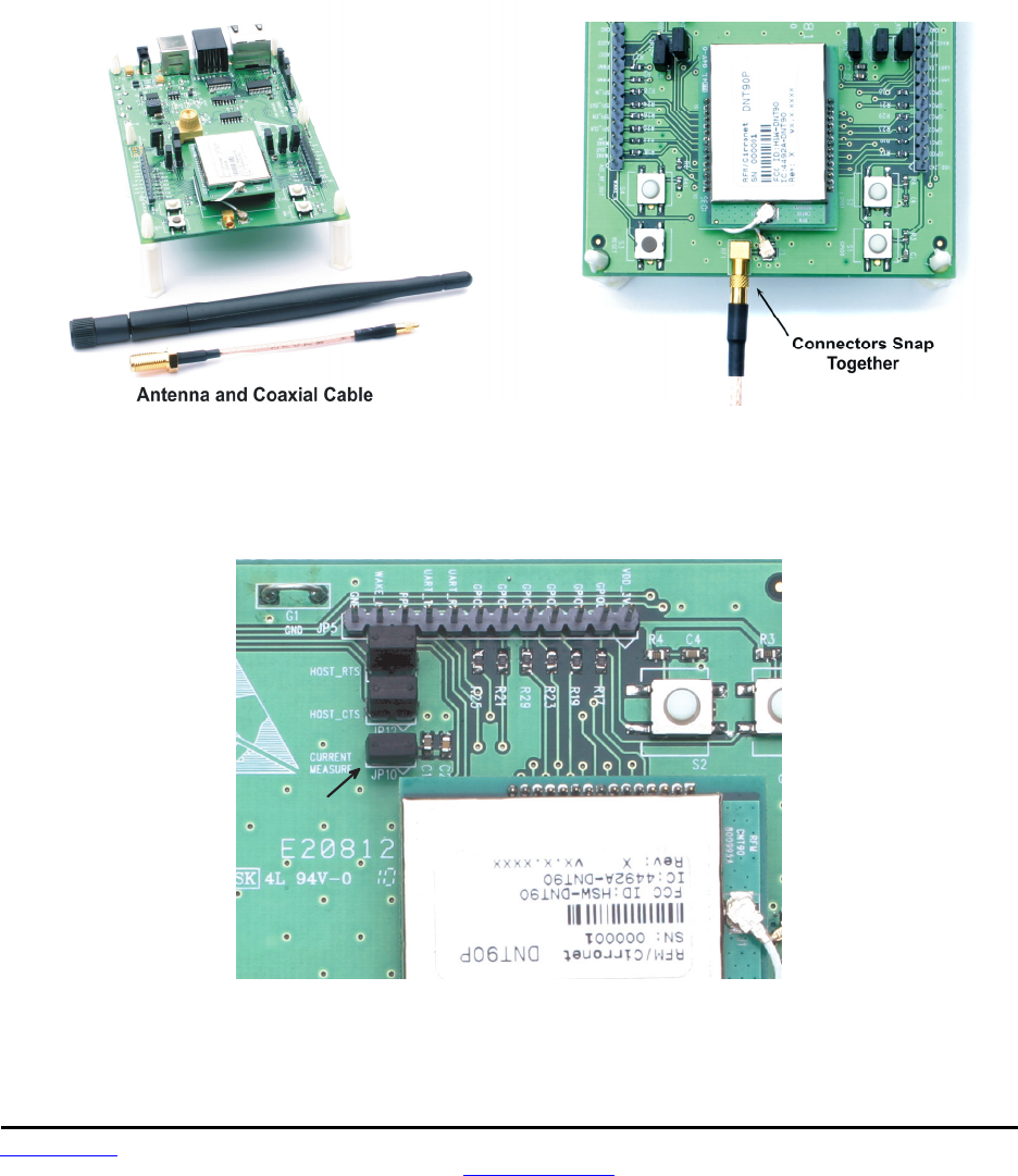
8.4 Developer’s Kit Hardware Assembly
Observe ESD precautions when handling the kit circuit boards. when shipped, the DNT90P radios and
U.FL coax jumper cables are installed in the interface boards, as shown in Figure 8.4.1. If a DNT90P ra-
dio and/or the U.FL jumper cable has been unplugged after receipt, confirm the DNT90P is correctly
plugged into its interface board with the radio oriented so that its U.FL connector is next to the U.FL con-
nector on the interface board, as shown in Figure 8.4.2. Also check the radio’s alignment in the socket on
the interface board. No pins should be hanging out over the ends of the connector. Next, screw each di-
pole antenna into and adaptor cable and “snap” the other end of the adaptor cable into the MMCX RF
connector on the development board as shown in Figure 8.4.2.
Figure 8.4.1 Figure 8.4.2
As shown in Figure 8.4.3, confirm there is a jumper on J10 (this jumper can be removed later and a cur-
rent meter connected across J10 to measure just the DNT90’s current consumption during operation).
J P 1 0
Figure 8.4.3
Preliminary
www.RFM.com Technical support +1.678.684.2000 Page 61 of 80
© 2010-2012 by RF Monolithics, Inc. E-mail: tech_sup@rfm.com DNT90 Integration Guide - 05/10/12
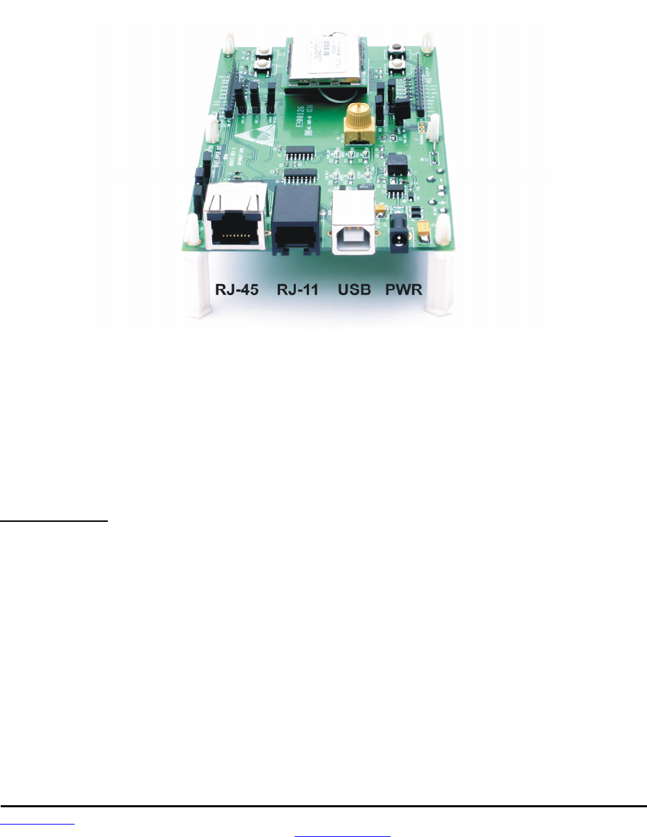
There are three serial connectors and a power connector on the end of each interface board, as shown in
Figure 8.4.4. The RJ-45 connector provides an RS232 interface to the DNT90P’s main serial port. The
USB connector provides an optional interface to the radio’s main serial port. The RJ-11 connector pro-
vides an RS232 interface to the radio’s optional diagnostic port. The DNT90 Demo utility program runs on
the radio’s main port.
Figure 8.4.4
Many desktop PCs have a built-in serial port capable of operation at 9600 bps. The kit can be run satis-
factorily at the 9600 bps data rate, but not at its fastest throughput. Use the RJ-45 to DB-9F cable as-
semblies for serial port operation.
Optionally, the kit development boards can be run from USB ports. Plugging in the USB cable automati-
cally switches operation from the RJ-45 connector. The USB interface is based on an FT232RL serial-to-
USB converter IC manufactured by FTDI. The FT232RL driver files are located in the i386 and AMD64
folders on the kit CD, and the latest version of the drivers can downloaded from the FTDI website,
www.ftdichip.com. The drivers create a virtual COM port on the PC. Power the Base using one of the
supplied wall-plug power supplies. Next connect the Base to the PC with a USB cable. The PC will find
the new USB hardware and open a driver installation dialog box. Enter the letter of the drive holding the
kit CD and click Continue. The installation dialog will run twice to complete the FT232R driver installation.
8.5 DNT90 Utility Program
The DNT90 utility program requires only one PC for initial kit operation and sensor applications (ADC,
DAC and digital I/O). Two serial/USB ports are required for bidirectional serial communications. Section
8.6 below covers using the DNT90 Demo utility program for initial kit operation and familiarization. Section
8.6.1 covers serial message communication and radio configuration.
Preliminary
www.RFM.com Technical support +1.678.684.2000 Page 62 of 80
© 2010-2012 by RF Monolithics, Inc. E-mail: tech_sup@rfm.com DNT90 Integration Guide - 05/10/12
8.6 Initial Kit Operation
Create a file folder on the PC and copy the contents of the kit CD into the folder.
Connect the Base to the PC and power up the Base using a wall-plug power supply.
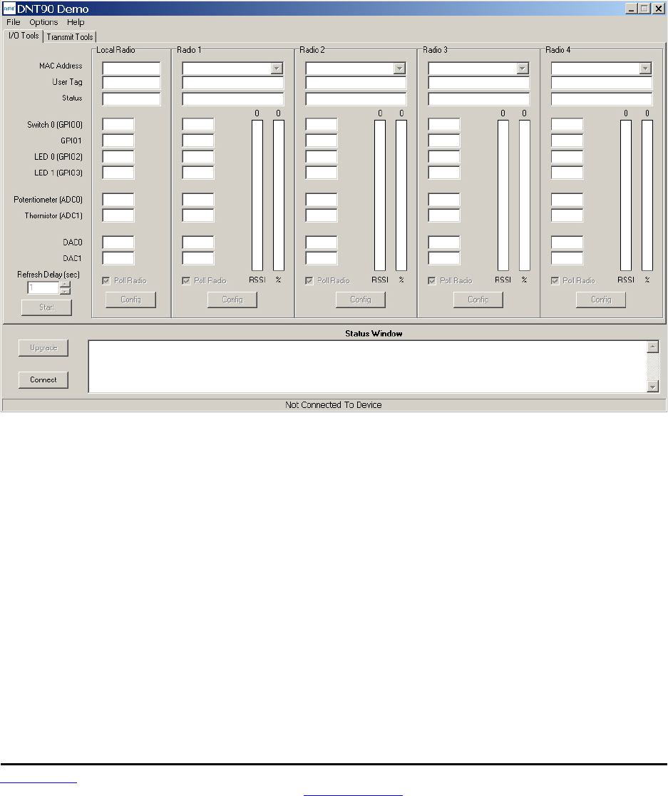
The DNT90 Demo utility program is located in the PC Programs folder. The DNT90 Demo utility program
requires no installation and can be simply copied to the PC and run. Start the utility program on the PC.
The start-up window is shown in Figure 8.6.1.
Figure 8.6.1
Preliminary
www.RFM.com Technical support +1.678.684.2000 Page 63 of 80
© 2010-2012 by RF Monolithics, Inc. E-mail: tech_sup@rfm.com DNT90 Integration Guide - 05/10/12
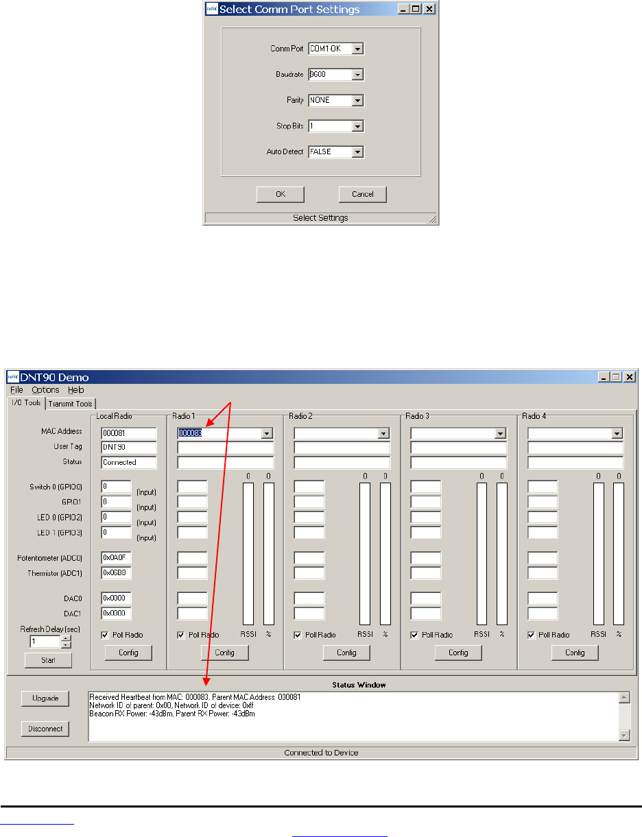
Click on Connect to open the Select Comm Port Settings dialog box, as shown in Figure 8.6.2. If
necessary, set the baud rate to 9600 bps. Set the CommPort to match the serial port connected to the
Base, either the hardware port or the USB virtual serial port. Then click OK to activate the serial
connection.
Figure 8.6.2
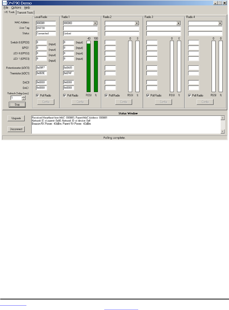
At this point the utility program will collect data from the Base, filling in the Local Radio column as shown
in Figure 8.6.3. Next power up the Remote using a wall-plug power supply. The Remote will transmit a
“heartbeat” message on power up as shown in the Status Window. Click on the drop-down box at the top
of the Radio 1 column and load the MAC Address for the Remote from the heartbeat message. Next
press the Start button using the default 1 second Refresh Delay.
Figure 8.6.3
Preliminary
www.RFM.com Technical support +1.678.684.2000 Page 64 of 80
© 2010-2012 by RF Monolithics, Inc. E-mail: tech_sup@rfm.com DNT90 Integration Guide - 05/10/12
The utility program will display updated data on the Remote in the Radio 1 column, including bar graphs
of RSSI signal strength in dBm and percent packet success rate, as shown in Figure 8.6.4. Adjusting the
large pot on the Remote can be observed on the Potentiometer (ADC0) row.
Figure 8.6.4
Note: If the Remote is powered up before the DNT90 Demo program is running and connected to the
Base, the initial Remote heartbeat will be missed and it will be necessary to manually enter the Remote’s
MAC address in the MAC Address field under Radio 1 and then press the Enter key to display the Re-
mote information.
If any difficulty is encountered in setting up the DNT90DK development kit, contact RFM’s module tech-
nical support group. The phone number is +1.678.684.2000. Phone support is available from 8:30 AM to
5:30 PM US Eastern Time Zone, Monday through Friday. The E-mail address is tech_sup@rfm.com.
Preliminary
www.RFM.com Technical support +1.678.684.2000 Page 65 of 80
© 2010-2012 by RF Monolithics, Inc. E-mail: tech_sup@rfm.com DNT90 Integration Guide - 05/10/12
8.6.1 Serial Communication and Radio Configuration
Connect PCs to both the Base and the Remote for serial communication testing (alternately one PC can
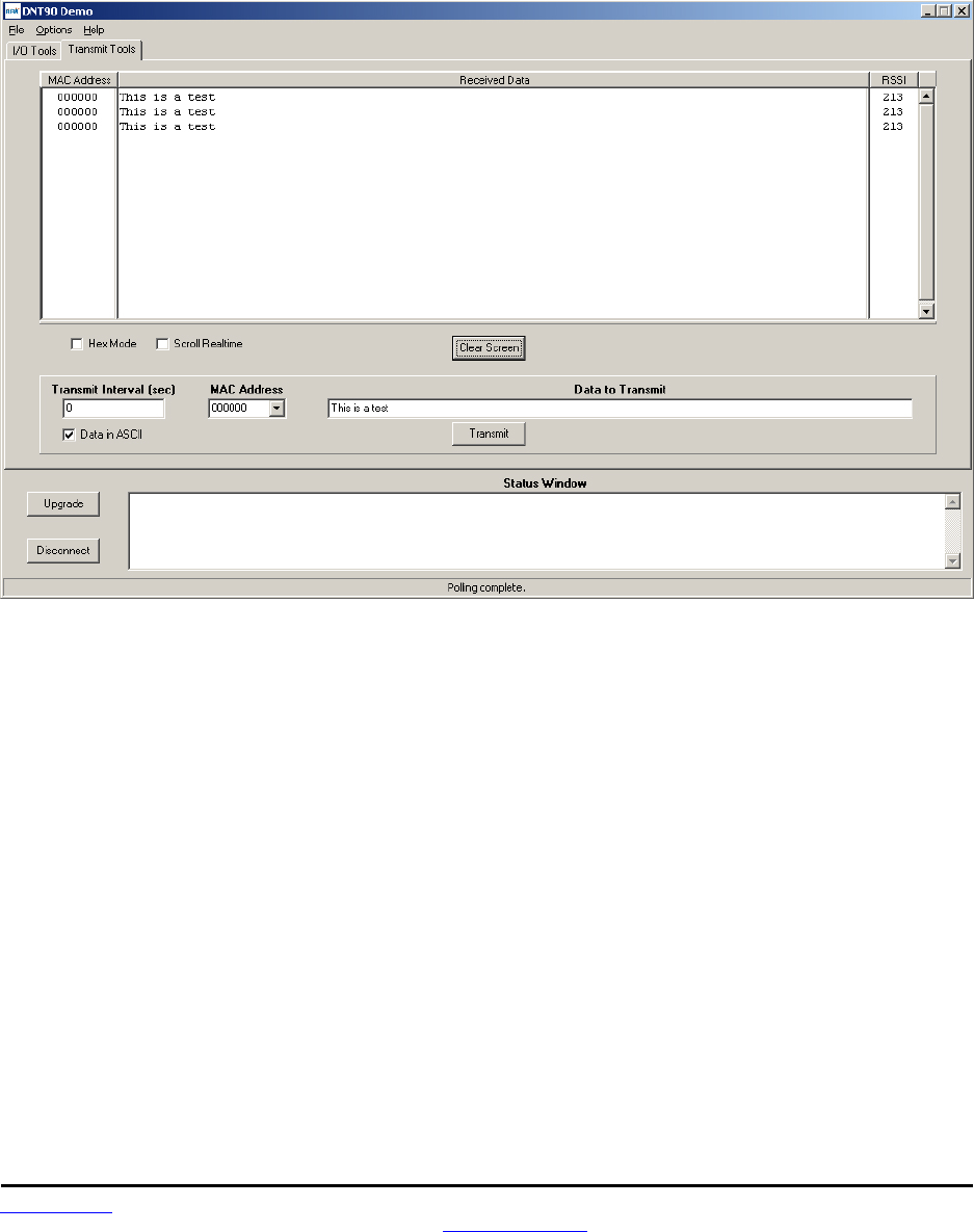
be used with two serial ports and two instances of the DNT90 Demo program running). Click the Stop
button under the Refresh Delay label on the I/O Tools tab and move to the Transmit Tools tab, as shown
in Figure 8.6.1.1.
Figure 8.6.1.1
Pressing the Transmit button on this screen sends the message in the Data to Transmit text box to the
selected MAC Address. Note that the MAC address a remote uses for the base is 0x000000. Data sent to
the local radio is displayed in the Received Data text box. Received data can be displayed as ASCII
(default) or in Hexadecimal format by checking the Hex Mode check box. When the Transmit Interval is
set to zero, Data to Transmit is sent once when the Transmit button is clicked. When the Transmit Interval
is set to a positive number, Pressing the Transmit button once will cause a transmission each transmit
interval (seconds) until the button is pressed again.
Preliminary
www.RFM.com Technical support +1.678.684.2000 Page 66 of 80
© 2010-2012 by RF Monolithics, Inc. E-mail: tech_sup@rfm.com DNT90 Integration Guide - 05/10/12
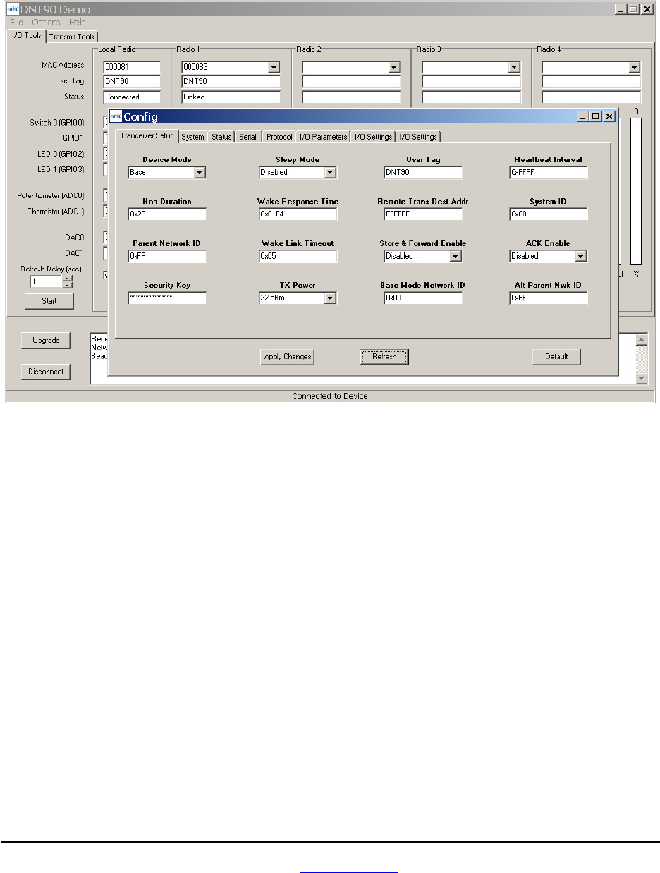
Returning to the I/O Tools tab, the multi-tab Configuration window for each radio can be accessed by
clicking on its Config button. The data presented on the first six tabs corresponds to configuration register
Banks 0 through 5 as discussed in Section 4.2 above, with the data on the next two tabs corresponding to
configuration register Bank 6.
Figure 8.6.1.2
The Transceiver Setup Tab is shown in Figure 8.6.1.2 and corresponds to Bank 0. The current values of
each Bank 0 parameter are displayed and can be updated by selecting from the drop-down menus or
entering data from the keyboard, and then pressing the Apply Changes button. Note that data is
displayed and entered in Big-Endian order. The utility program automatically reorders multi-byte data to
and from Little-Endian order when building or interpreting messages.
Preliminary
www.RFM.com Technical support +1.678.684.2000 Page 67 of 80
© 2010-2012 by RF Monolithics, Inc. E-mail: tech_sup@rfm.com DNT90 Integration Guide - 05/10/12
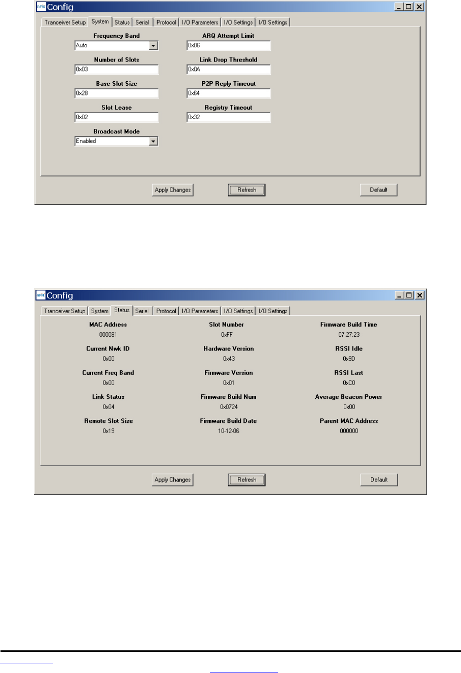
Figure 8.6.1.3
Figure 8.6.1.3 shows the System tab contents, corresponding to Bank 1. The current values of each pa-
rameter are displayed and can be updated by selecting from the drop-down menu or entering data from
the keyboard, and then pressing the Apply Changes button. Note that Bank 1 holds configuration parame-
ters for the base only except for Broadcast Mode, which applies to both the base and the remotes.
Figure 8.6.1.4
Figure 8.6.1.5 shows the Status tab contents, corresponding to Bank 2. Note the Status tab contains
read-only parameters.
Preliminary
www.RFM.com Technical support +1.678.684.2000 Page 68 of 80
© 2010-2012 by RF Monolithics, Inc. E-mail: tech_sup@rfm.com DNT90 Integration Guide - 05/10/12
Figure 8.6.1.5
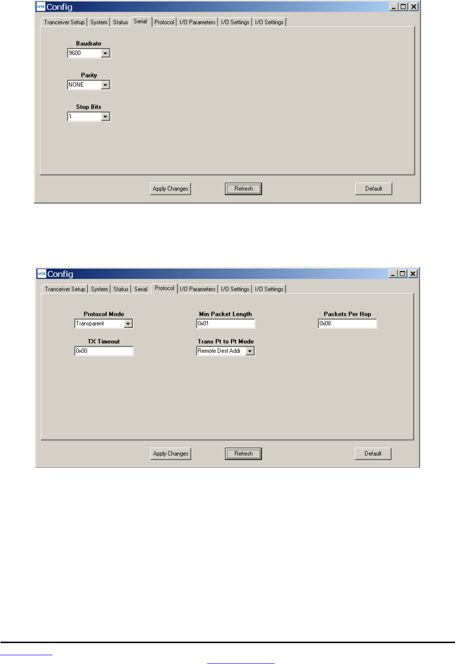
Figure 8.6.1.5 shows the Serial tab contents corresponding to the serial parameters in Bank 3. The val-
ues shown are the defaults for serial port operation.
Figure 8.6.1.6
Figure 8.6.1.6 shows the Protocol tab contents, corresponding to Bank 4. Transparent serial data com-
munication is currently chosen.
Preliminary
www.RFM.com Technical support +1.678.684.2000 Page 69 of 80
© 2010-2012 by RF Monolithics, Inc. E-mail: tech_sup@rfm.com DNT90 Integration Guide - 05/10/12
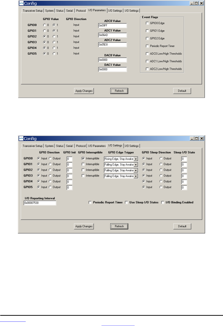
Figure 8.6.1.7
Figure 8.6.1.7 shows the I/O Parameters tab contents, corresponding to Bank 5. All GPIO ports are con-
figured as inputs. The 12-bit ADC input readings and DAC output settings are given in Big-Endian byte
order. Event flags are presented on the right side of the window.
Figure 8.6.1.8
Figure 8.6.1.8 shows the first I/O Settings tab contents, corresponding to Bank 6 GPIO configurations
other than alternate GPIO functions. This tab allows the direction of the GPIO ports to be set both for ac-
tive and sleep modes, and in the case of GPIO outputs, the initial power up states and sleep mode states
to be set. When GPIO ports 0 - 3 are configured as inputs, event interrupts can be set for them with check
boxes. The type of interrupt trigger is selected from the drop-down boxes to the right of the check boxes.
Periodic I/O reporting, reporting interval and enable/disable sleep I/O states and I/O binding can also be
configured under this tab.
Preliminary
www.RFM.com Technical support +1.678.684.2000 Page 70 of 80
© 2010-2012 by RF Monolithics, Inc. E-mail: tech_sup@rfm.com DNT90 Integration Guide - 05/10/12
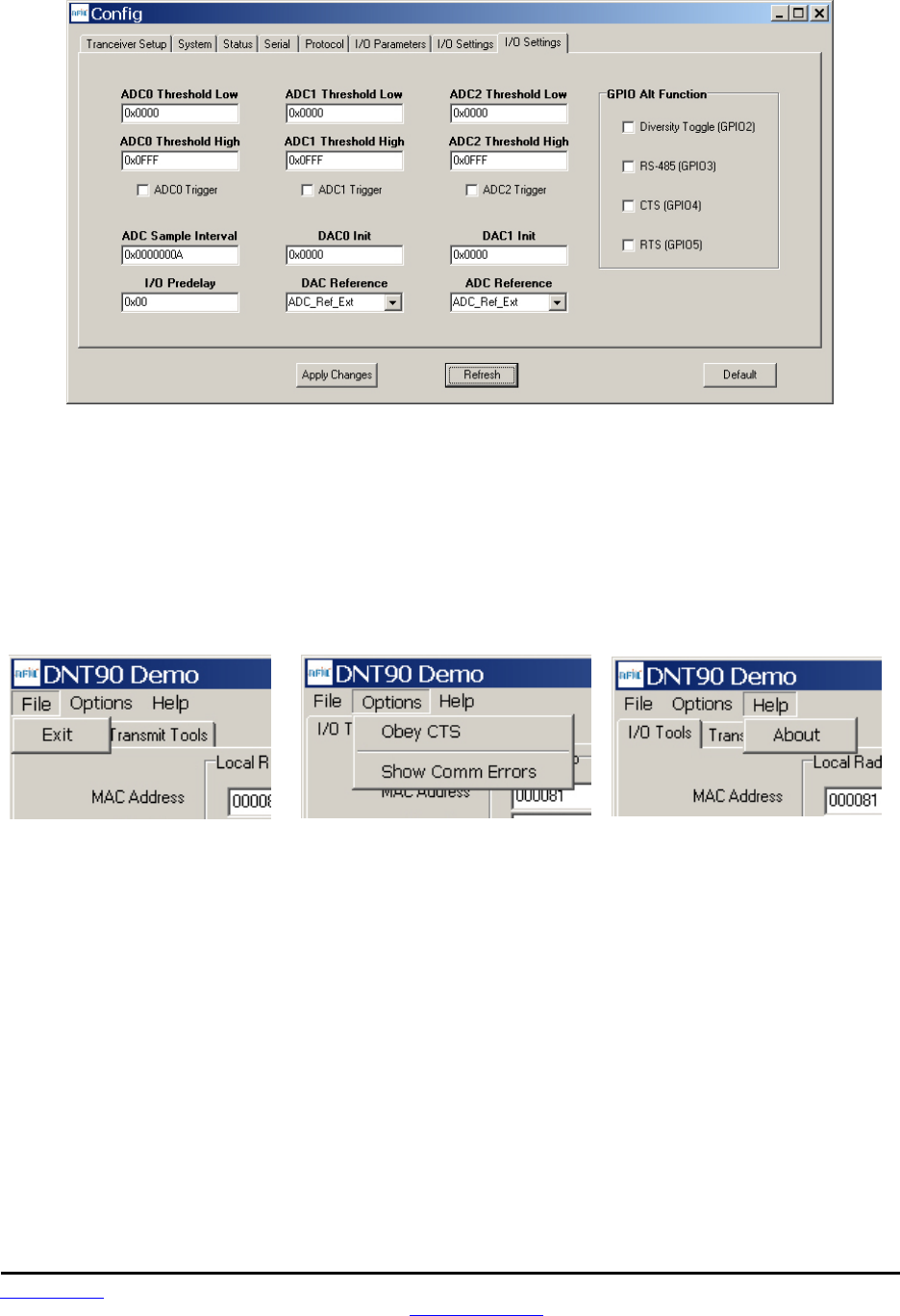
Figure 8.6.1.9
Figure 8.6.1.9 shows the second I/O Setup tab contents, corresponding to Bank 6 ADC input and DAC
output parameters. The ADC and DAC reference voltages, the ADC sampling interval, the high and low
ADC thresholds for event reporting and event reporting triggers on each ADC channel can be set, along
with the initial output values for each DAC channel. The event reporting I/O predelay and alternate GPIO
functions can also be set from this tab.
The DNT90 Demo Utility File, Options and Help menus are shown in Figure 8.7.8.
Figure 8.7.8
Preliminary
www.RFM.com Technical support +1.678.684.2000 Page 71 of 80
© 2010-2012 by RF Monolithics, Inc. E-mail: tech_sup@rfm.com DNT90 Integration Guide - 05/10/12
8.7 DNT90 Interface Board Features
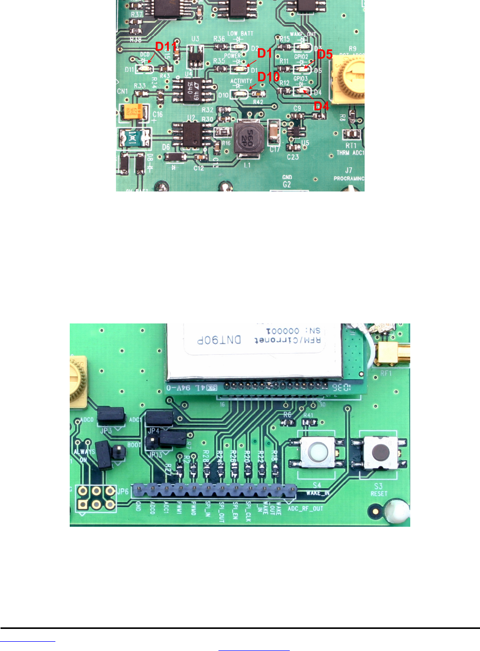
The locations of the LEDs on the interface board that are used by the DNT90 are shown in Figure 8.8.1.
Figure 8.8.1
DCD LED, D11, illuminates on a router or remote to indicate it is registered with its parent and can partic-
ipate in RF communications. The DCD LED illuminates on the base when one or more routers or remotes
are registered to it, unless the base has been configured to assert DCD on power up. In this case it will be
on as long as the development board is powered. Activity LED, D10, illuminates when transmitting or re-
ceiving RF data. Power LED, D1, illuminates with the DNT90 and its interface board are powered. GPIO2
LED, D5, and GPIO3 LED, D4, can be controlled by configuring GPIO2 and GPIO3 as outputs on the
DNT90. These LEDs are illuminated with a logic high signal.
Figure 8.8.2
Figure 8.8.2 shows the connectors and switches to the right of the DNT90P mounting socket. JP3 and
JP4 normally have shorting plugs installed as shown in Figure 8.8.2. JP3 connects ADC0 to the yellow
potentiometer. Clockwise rotation of the potentiometer increases the voltage. JP4 connects ADC1 to a
thermistor temperature sensor. The DNT90 has its own boot loader utility that allows the protocol firm-
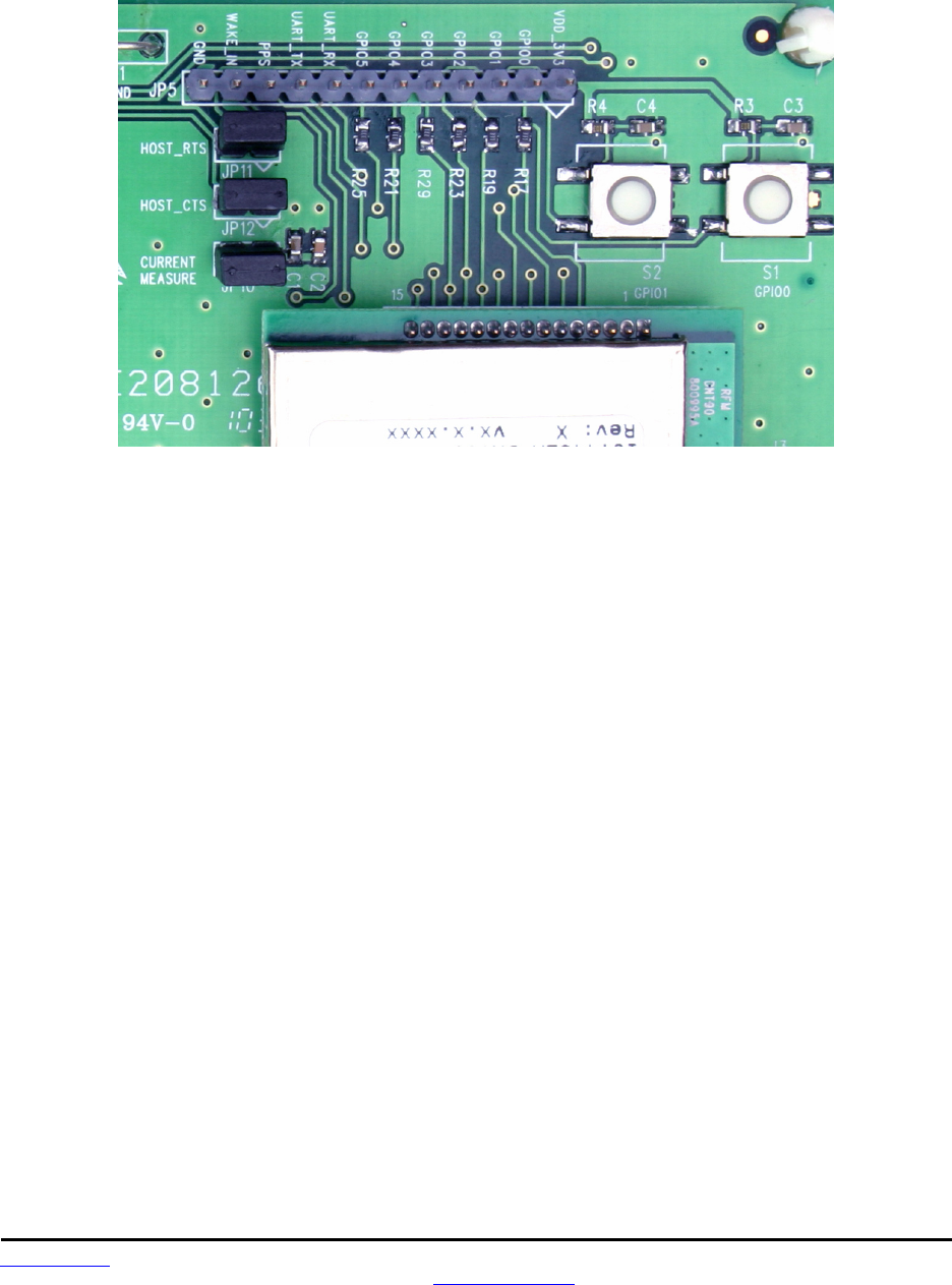
Preliminary
www.RFM.com Technical support +1.678.684.2000 Page 72 of 80
© 2010-2012 by RF Monolithics, Inc. E-mail: tech_sup@rfm.com DNT90 Integration Guide - 05/10/12
ware to be installed with a terminal program that supports YMODEM. The boot loader is activated with a
shorting plug on JP13. Pin strip J6 provides access to various DNT90 pins as shown on the silkscreen.
Pressing switch SW3 will reset the DNT90P. Switch S4 is not used with the DNT90.
Figure 8.8.3
Figure 8.8.3 shows the connectors to the left of the DNT90P mounting socket. Pressing switch SW1
switches GPIO0 from logic high to low, and pressing SW2 switches GPIO1 from logic high to low. The
DNT90P interface board includes a 5 V regulator to regulate the input from the 9 V wall-plug power sup-
ply. Do not attempt to use the 9 V wall-plug power supply to power the DNT90P directly. The maximum
allowed voltage input to the DNT90P is 5.5 V.

Preliminary
www.RFM.com Technical support +1.678.684.2000 Page 73 of 80
© 2010-2012 by RF Monolithics, Inc. E-mail: tech_sup@rfm.com DNT90 Integration Guide - 05/10/12
9.0 Troubleshooting
DNT90 not responding - make sure /RESET is not asserted (logic low). Make sure the host serial port
settings match the DNT90 serial port settings.
Can not enter protocol mode - make sure the host data rate is correct. The DNT90 defaults to 9.6 kbps. If
using the EnterProtocolMode command, send the complete protocol format for this command.
A remote never detects carrier (DCD) - check that the base is running, and that the remote’s Sys-
temNwkID is the same as the base, and that the ParentNwkID parameter is the same as the base, or is
set to 0xFF. Also make sure that the security keys are the same.
Carrier is detected, but no data appears to be received - if /HOST_RTS is enabled, make sure it is as-
serted (logic low) to enable character flow from the DNT90.
Range is extremely limited - this is usually a sign of a poor antenna connection or the wrong antenna.
Check that the antenna is firmly connected. If possible, remove any obstructions near the antenna.
9.1 Diagnostic Port Commands
The diagnostic port shares its RX and TX signal lines with the Activity and DCD indications, respectively.
Consequently, the debug port feature must be enabled before being used (Bank 0xFF). The change must
be saved and the module then needs to be reset for this to take effect. The diagnostic port is defaulted to
38.4 kbps, 8N1.
The diagnostic port supports the following user commands:
rbr <bank> <reg> <span> - read a parameter register’s value from the module.
rbw <bank> <reg> <span> <value> [<value> <value>] - write a parameter register’s value
with a span of up to 3 bytes
stat <option> - option = 0 is off, option = 1 displays DataTx/AckRx for a hop
sequence in time order, and option = 2 displays any packet RX or packet error for a hop
sequence in frequency order.
base <0 or 1> - For a router, this determines whether the stat option displays data
associated with its operation as a base (1) or as a remote (0).

Preliminary
www.RFM.com Technical support +1.678.684.2000 Page 74 of 80
© 2010-2012 by RF Monolithics, Inc. E-mail: tech_sup@rfm.com DNT90 Integration Guide - 05/10/12
10.0 Appendices
10.1 Ordering Information
DNT90C: transceiver module for solder-pad mounting
DNT90P: transceiver module for pin-socket mounting
10.2 Technical Support
For DNT90 technical support call RFM at (678) 684-2000 between the hours of 8:30 AM and 5:30 PM
Eastern Time
Preliminary
www.RFM.com Technical support +1.678.684.2000 Page 75 of 80
© 2010-2012 by RF Monolithics, Inc. E-mail: tech_sup@rfm.com DNT90 Integration Guide - 05/10/12
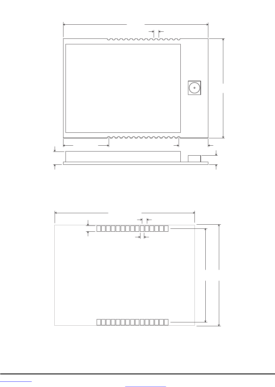
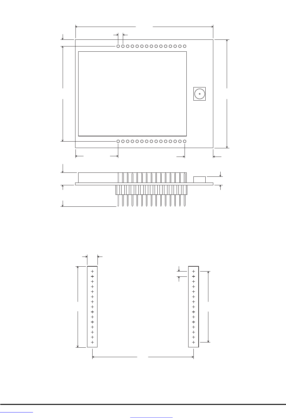
10.3 DNT90 Mechanical Specifications
1 . 4 5 0
( 3 6 . 8 )
0 . 9 8 0
( 2 7 . 9 )
D N T 9 0 C O u t l i n e a n d M o u n t i n g D i m e n s i o n s
0 . 0 5 0 ( 1 . 2 7 )
1
T o p V i e w
0 . 1 2 5
( 3 . 1 8 )
1 5
1 6 3 0
D i m e n s i o n s i n i n c h e s ( m m )
0 . 0 9 0
0 . 4 5 0 ( 1 1 . 4 ) 0 . 3 0 0 ( 7 . 6 2 )
Figure 10.3.1
0 . 0 6 0 ( 1 . 5 2 )
1 . 4 5 0 ( 3 6 . 8 )
0 . 9 8 0
( 2 4 . 9 )
D N T 9 0 C S o l d e r P a d D i m e n s i o n s
0 . 0 5 0 ( 1 . 2 7 )
1
T o p V i e w
1 5
1 6 3 0
D i m e n s i o n s i n i n c h e s ( m m )
0 . 0 3 5 ( 0 . 8 9 )
1 . 0 4 0
( 2 6 . 4 )
Figure 10.3.2
Preliminary
www.RFM.com Technical support +1.678.684.2000 Page 76 of 80
© 2010-2012 by RF Monolithics, Inc. E-mail: tech_sup@rfm.com DNT90 Integration Guide - 05/10/12
0 . 0 6 0
( 1 . 5 2 )
1 . 4 5 0
( 3 6 . 8 )
1 . 1 0 0
( 2 7 . 9 )
D N T 9 0 P O u t l i n e a n d M o u n t i n g D i m e n s i o n s
0 . 0 5 0 ( 1 . 2 7 )
1
T o p V i e w
0 . 1 2 5
( 3 . 1 8 )
1 5
1 6 3 0
D i m e n s i o n s i n i n c h e s ( m m )
0 . 4 5 0 ( 1 1 . 4 )
0 . 0 9 0
( 2 . 2 9 )
0 . 2 2 5
( 5 . 7 2 )
0 . 9 8 0
( 2 4 . 9 )
0 . 3 0 0 ( 7 . 6 2 )
Figure 10.3.3
0.980
( 2 4 . 9 )
0.050
( 1 . 2 7 )
0.700
( 1 7 . 8 )
0.100
( 2 . 5 4 )
0.800
( 2 0 . 3 )
D N T 9 0 P I n t e r f a c e C o n n e c t o r
P C B L a y o u t D e t a i l
C o n n e c t o r s a r e S A M T E C
S L M - 1 1 5 - 0 1 - G - S
o r E q u i v a l e n t
D i m e n s i o n s a r e i n i n c h e s ( m m )
Figure 10.3.4
Preliminary
www.RFM.com Technical support +1.678.684.2000 Page 77 of 80
© 2010-2012 by RF Monolithics, Inc. E-mail: tech_sup@rfm.com DNT90 Integration Guide - 05/10/12
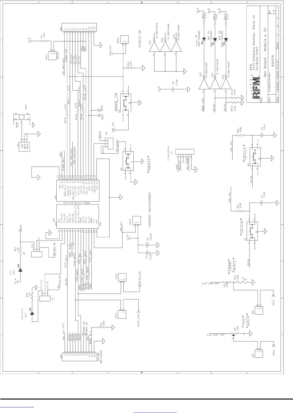
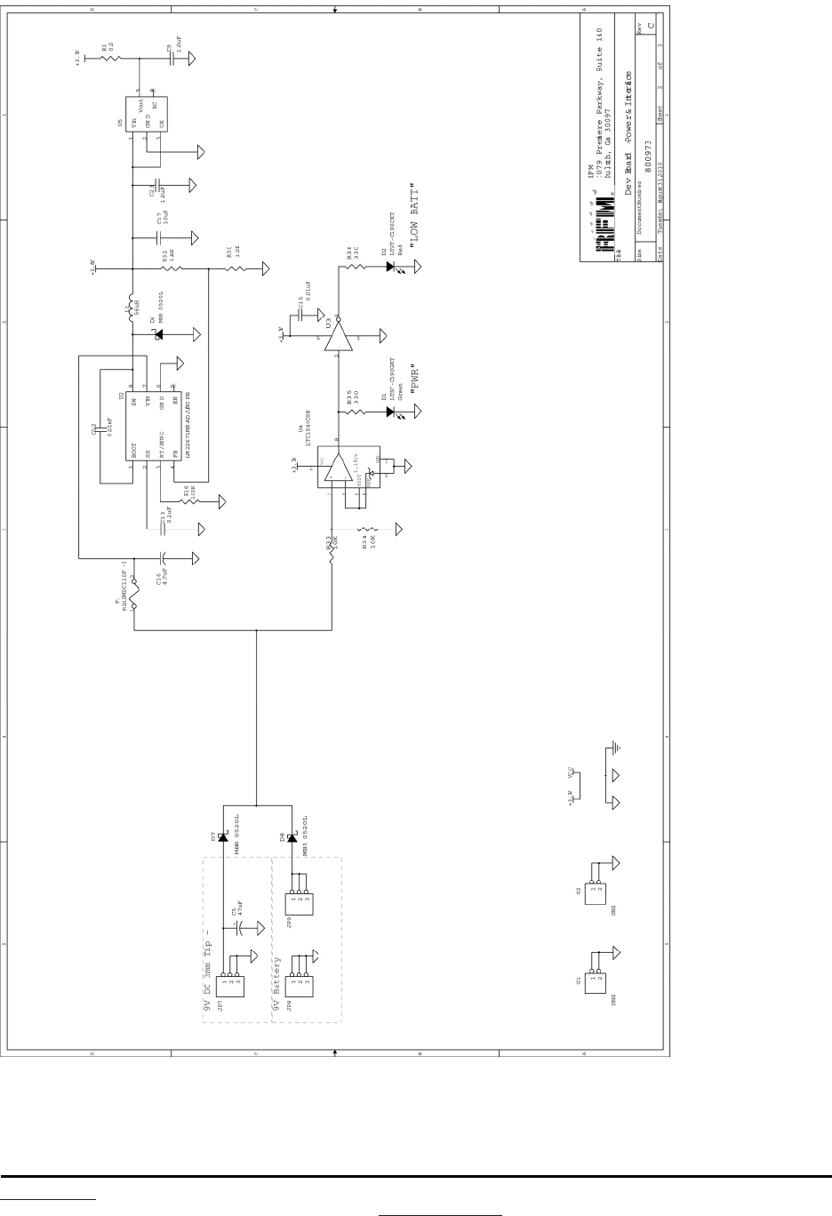
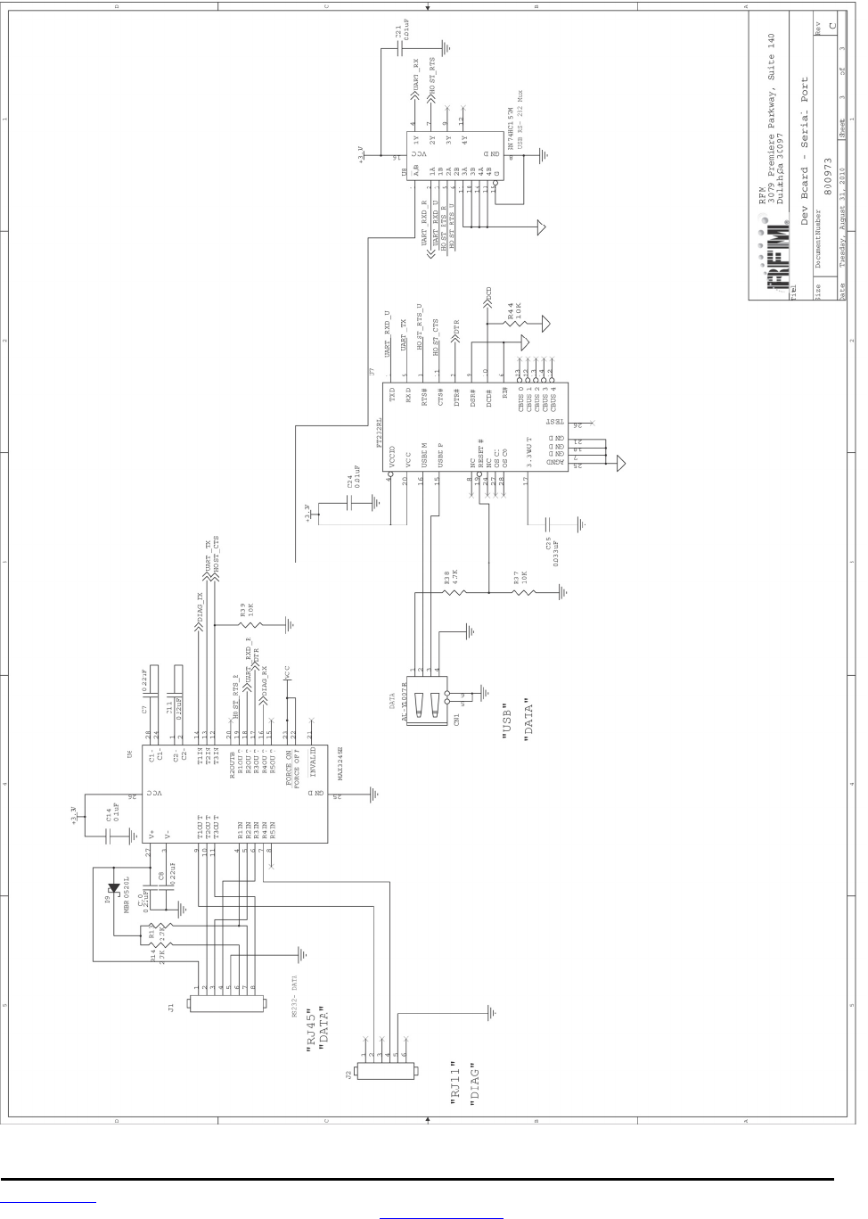
10.4 DNT90 Development Board Schematic
Preliminary
www.RFM.com Technical support +1.678.684.2000 Page 78 of 80
© 2010-2012 by RF Monolithics, Inc. E-mail: tech_sup@rfm.com DNT90 Integration Guide - 05/10/12
Preliminary
www.RFM.com Technical support +1.678.684.2000 Page 79 of 80
© 2010-2012 by RF Monolithics, Inc. E-mail: tech_sup@rfm.com DNT90 Integration Guide - 05/10/12

Preliminary
www.RFM.com Technical support +1.678.684.2000 Page 80 of 80
© 2010-2012 by RF Monolithics, Inc. E-mail: tech_sup@rfm.com DNT90 Integration Guide - 05/10/12
11.0 Warranty
Seller warrants solely to Buyer that the goods delivered hereunder shall be free from defects in materials
and workmanship, when given normal, proper and intended usage, for twelve (12) months from the date
of delivery to Buyer. Seller agrees to repair or replace at its option and without cost to Buyer all defective
goods sold hereunder, provided that Buyer has given Seller written notice of such warranty claim within
such warranty period. All goods returned to Seller for repair or replacement must be sent freight prepaid
to Seller’s plant, provided that Buyer first obtain from Seller a Return Goods Authorization before any
such return. Seller shall have no obligation to make repairs or replacements which are required by normal
wear and tear, or which result, in whole or in part, from catastrophe, fault or negligence of Buyer, or from
improper or unauthorized use of the goods, or use of the goods in a manner for which they are not de-
signed, or by causes external to the goods such as, but not limited to, power failure. No suit or action
shall be brought against Seller more than twelve (12) months after the related cause of action has oc-
curred. Buyer has not relied and shall not rely on any oral representation regarding the goods sold here-
under, and any oral representation shall not bind Seller and shall not be a part of any warranty.
THE PROVISIONS OF THE FOREGOING WARRANTY ARE IN LIEU OF ANY OTHER WARRANTY,
WHETHER EXPRESS OR IMPLIED, WRITTEN OR ORAL (INCLUDING ANY WARRANTY OR MER-
CHANT ABILITY OR FITNESS FOR A PARTICULAR PURPOSE). SELLER’S LIABILITY ARISING
OUT OF THE MANUFACTURE, SALE OR SUPPLYING OF THE GOODS OR THEIR USE OR DISPO-
SITION, WHETHER BASED UPON WARRANTY, CONTRACT, TORT OR OTHERWISE, SHALL NOT
EXCEED THE ACTUAL PURCHASE PRICE PAID BY BUYER FOR THE GOODS. IN NO EVENT
SHALL SELLER BE LIABLE TO BUYER OR ANY OTHER PERSON OR ENTITY FOR SPECIAL, IN-
CIDENTAL OR CONSEQUENTIAL DAMAGES, INCLUDING, BUT NOT LIMITED TO, LOSS OF PROF-
ITS, LOSS OF DATA OR LOSS OF USE DAMAGES ARISING OUT OF THE MANUFACTURE, SALE
OR SUPPLYING OF THE GOODS. THE FOREGOING WARRANTY EXTENDS TO BUYER ONLY AND
SHALL NOT BE APPLICABLE TO ANY OTHER PERSON OR ENTITY INCLUDING, WITHOUT LIMI-
TATION, CUSTOMERS OF BUYERS.
Part # M-0090-0002, Rev G