Murata Electronics North America DNT90 900MHz Transceiver Module User Manual 10 0314 W06 11 A Exhibit Cover
Murata Electronics North America 900MHz Transceiver Module 10 0314 W06 11 A Exhibit Cover
Contents
- 1. Manual
- 2. manual pt a
- 3. manual pt b
Manual
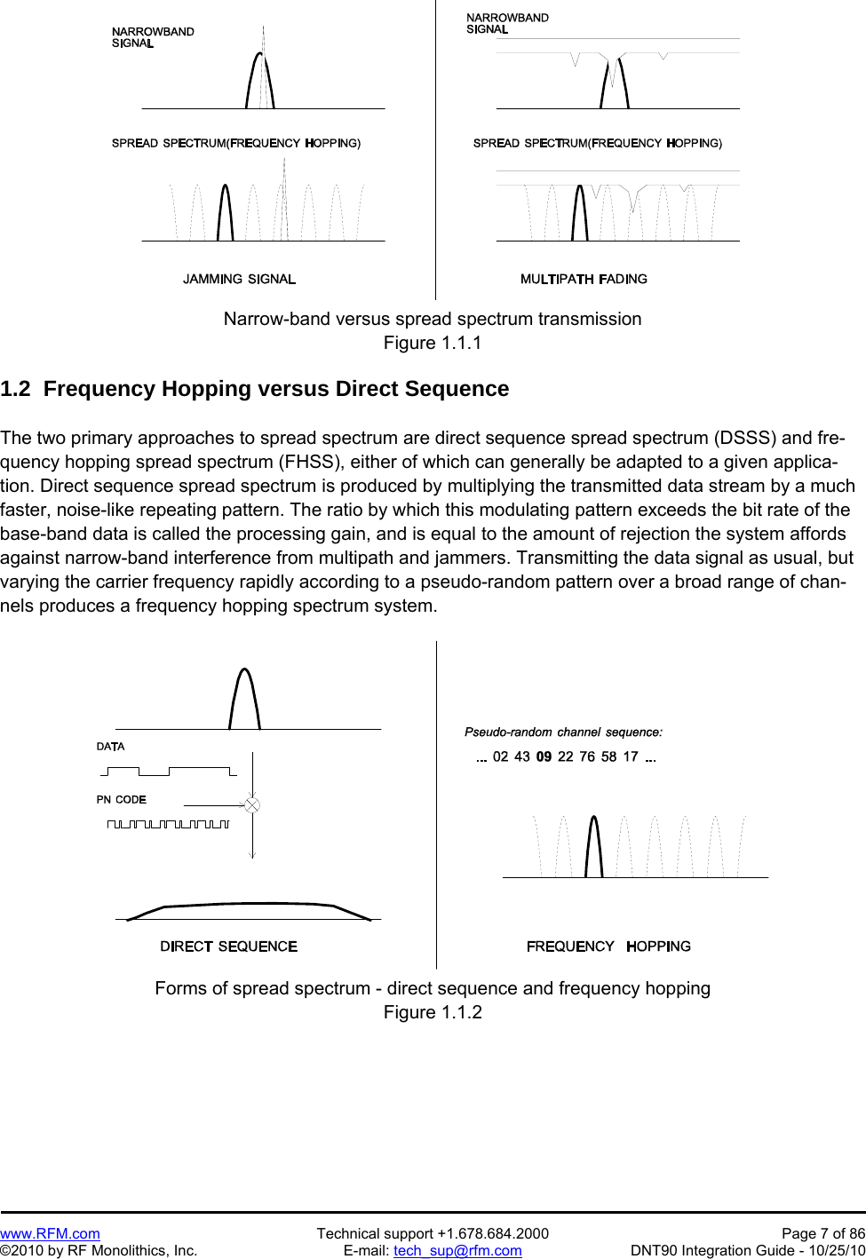
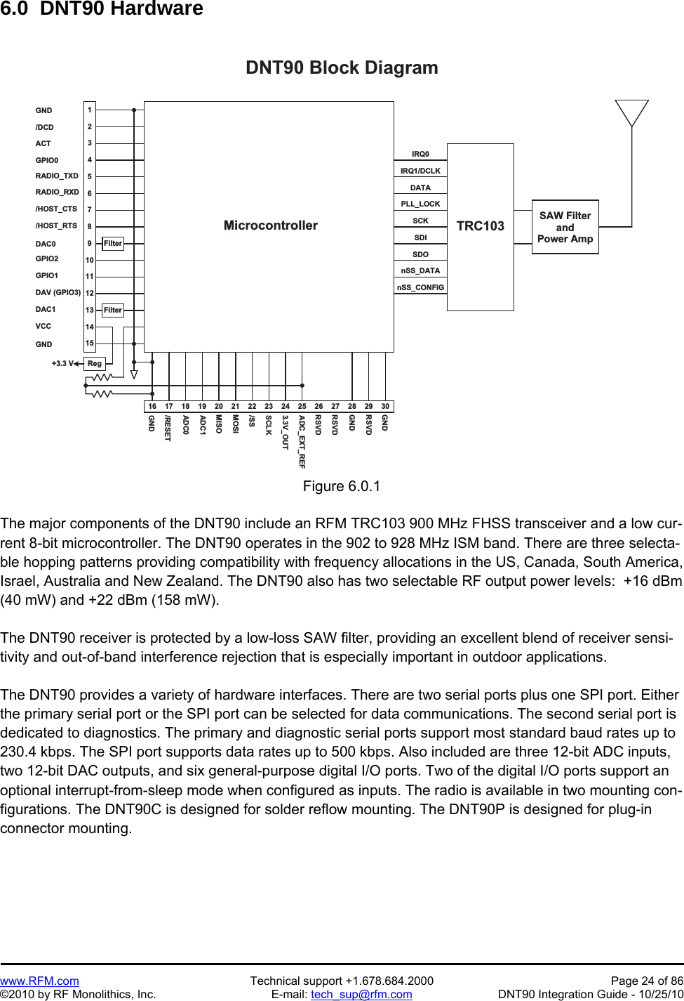
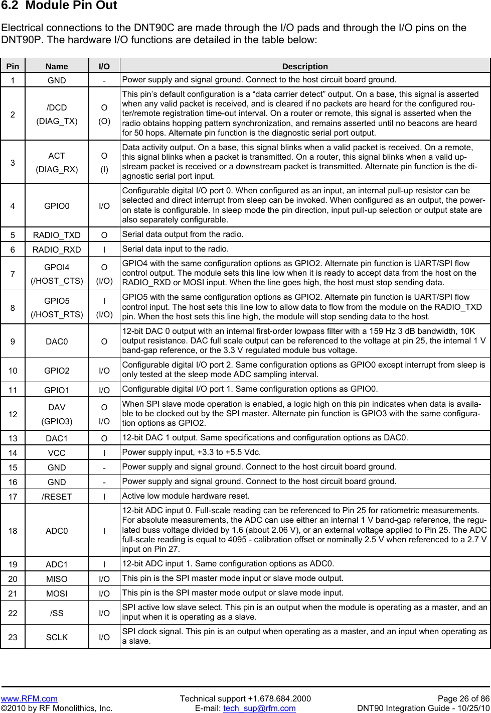
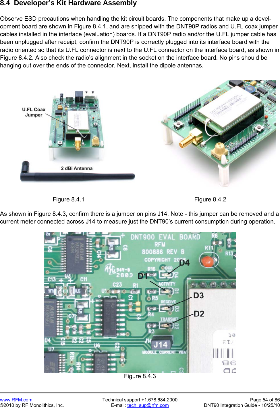
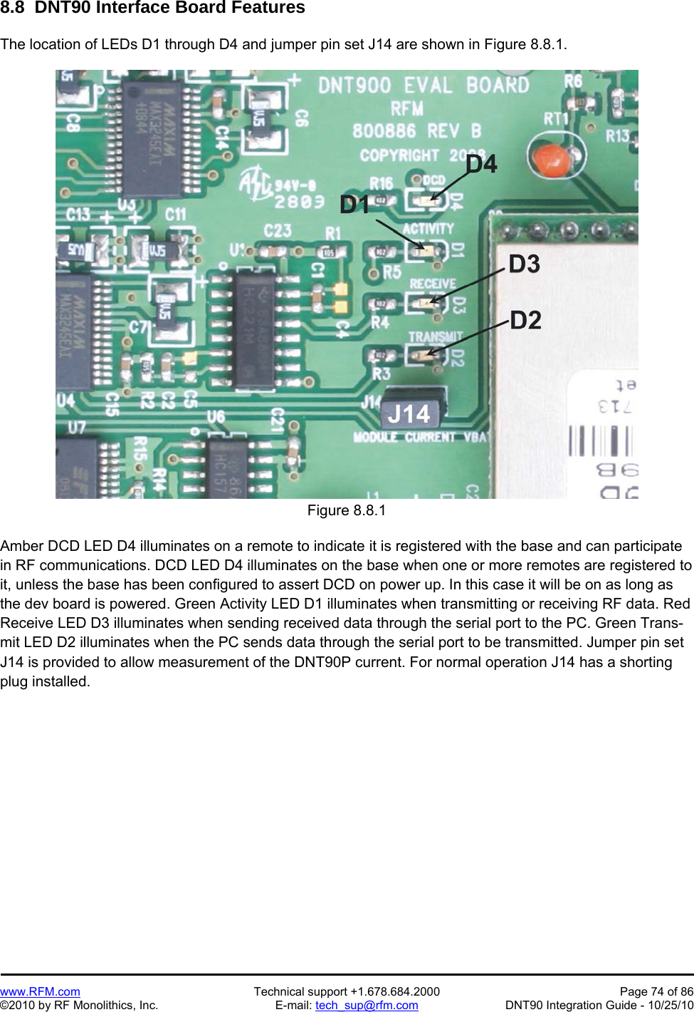
![www.RFM.com Technical support +1.678.684.2000 Page 8 of 86 ©2010 by RF Monolithics, Inc. E-mail: tech_sup@rfm.com DNT90 Integration Guide - 10/25/10 One disadvantage of direct sequence systems is that due to design issues related to broadband transmit-ters and receivers, they generally employ only a minimal amount of spreading, often no more than the minimum required by the regulating agencies. For this reason, the ability of DSSS systems to overcome fading and in-band jammers is relatively weak. By contrast, FHSS systems are capable of hopping throughout the entire band, statistically reducing the chances that a transmission will be affected by fad-ing or interference. This means that a FHSS system will degrade gracefully as the band gets noisier, while a DSSS system may exhibit uneven coverage or work well until a certain point and then give out completely. Because it offers greater immunity to interfering signals, FHSS is often the preferred choice for co-located systems. Since direct sequence signals are very wide, they can offer only a few non-overlapping chan-nels, whereas multiple hoppers can interleave, minimizing interference. Frequency hopping systems do carry some disadvantages, in that they require an initial acquisition period during which the receiver must lock on to the moving carrier of the transmitter before any data can be sent, which typically takes several seconds. In summary, frequency hopping systems generally feature greater coverage and channel utiliza-tion than comparable direct sequence systems. Of course, other implementation factors such as size, cost, power consumption and ease of implementation must also be considered before a final radio design choice can be made. 2.0 DNT90 System Overview A DNT90 radio can be configured to operate in one of three modes - base, remote or router. A base con-trols a DNT90 system, and interfaces to an application host such as a PC or Internet gateway. A remote functions to transmit or receive serial, digital (state) and analog data. A router alternates between func-tioning as a remote on one hop and a network base on the next hop. When acting as a remote, the router stores messages it receives from its parent, and then repeats the messages to its child radios when act-ing as a network base. Likewise, a router will store messages received from its child radios when acting as a base, and repeat them to its parent when acting as a remote. Any message addressed directly to a router is processed by the router rather than being repeated. 2.1 Point-to-Point Systems A DNT90 system contains at least one network. The simplest DNT90 topology is a point-to-point system, as shown in Figure 2.1.1. This system consists of a base and one remote forming a single network. Point-to-point systems are often used to replace wired serial connections. Point-to-point systems are also used to transmit switch positions or analog signals from one location to another. Figure 2.1.1 [replace with DNT90 graphics]](https://usermanual.wiki/Murata-Electronics-North-America/DNT90.Manual/User-Guide-1372651-Page-9.png)
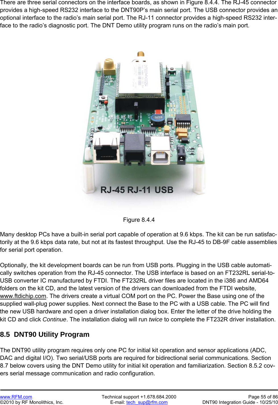
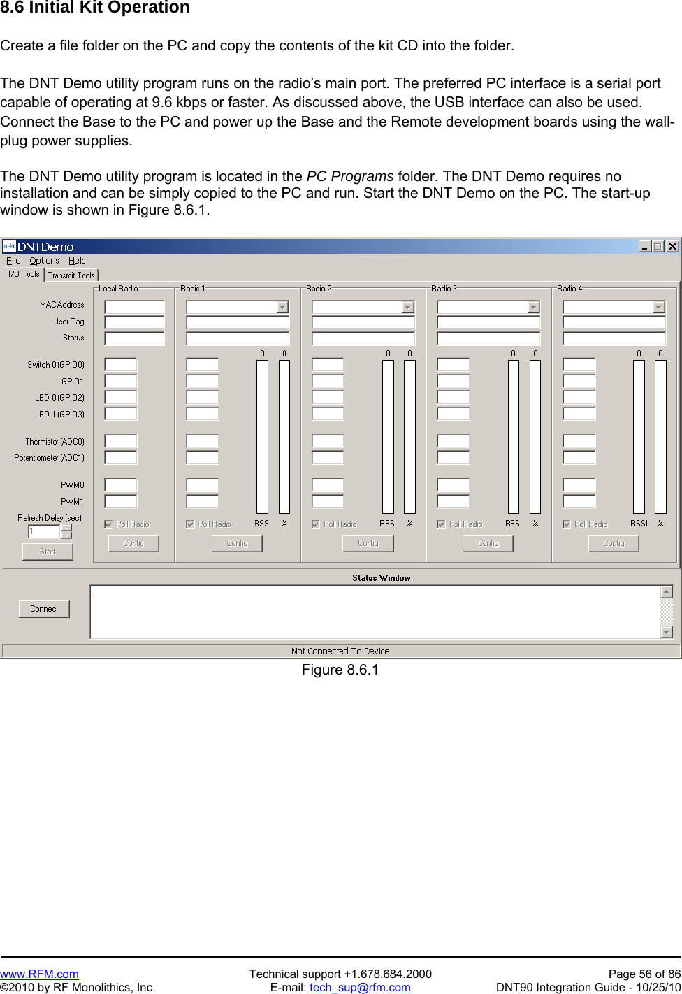
![www.RFM.com Technical support +1.678.684.2000 Page 9 of 86 ©2010 by RF Monolithics, Inc. E-mail: tech_sup@rfm.com DNT90 Integration Guide - 10/25/10 2.2 Point-to-Multipoint Systems Figure 2.2.1 shows the topology of a point-to-multipoint (star) system, which consists of a base and more than one remote in a single network. Point-to-multipoint systems are typically used for data, sensor and alarm systems. While most traffic in a point-to-multipoint system is between the base and the remotes, DNT90 technology also allows for peer-to-peer communication from one remote to another. Figure 2.2.1 [replace with DNT90 graphics] 2.3 Store-and-Forward Systems Figure 2.3.1 shows the topology of a store-and-forward system, which consists of a base, one or more routers, one or more remotes, and two or more networks. Networks in a store-and-forward system form around the base and each router. The base and the routers are referred to as the parents of the networks they form. The rest of the radios in each network are referred to as child radios. Note that a router can be a child of the base or another router while being the parent of its own network. Each network parent transmits beacons to allow child radios to synchronize with its hopping pattern and join its network. Differ-ent frequency hopping patterns are used by the parent radios in a system, minimizing interference be-tween networks. Store-and-forward systems are used to cover larger areas than is possible with point-to-point or point to-multipoint systems. The trade-off in store-and-forward systems is longer delivery times due to receiving and retransmitting a message several times. Store-and-forward systems are especially useful in applica-tions such as agriculture where data is only collected every hour or so. Figure 2.3.1 [replace with DNT90 graphics]](https://usermanual.wiki/Murata-Electronics-North-America/DNT90.Manual/User-Guide-1372651-Page-10.png)