Murata Electronics North America DNT90 Spread Spectrum Wireless Transceiver User Manual manual pt a

Murata Electronics North America Spread Spectrum Wireless Transceiver manual pt a
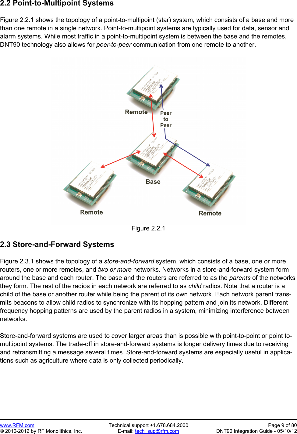
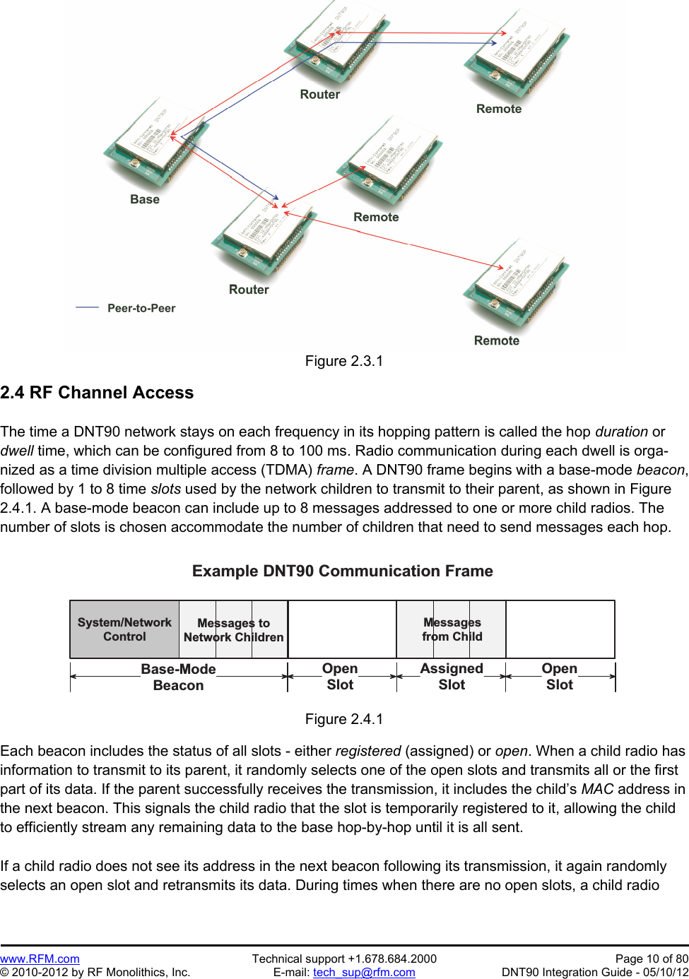
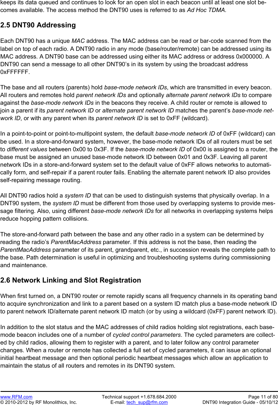
Contents

manual pt a

Preliminary   www.RFM.com  Technical support +1.678.684.2000  Page 1 of 80 © 2010-2012 by RF Monolithics, Inc.  E-mail: tech_sup@rfm.com  DNT90 Integration Guide - 05/10/12     DNT90 Series 900 MHz Spread Spectrum Wireless Transceivers   Integration Guide
Preliminary   www.RFM.com  Technical support +1.678.684.2000  Page 2 of 80 © 2010-2012 by RF Monolithics, Inc.  E-mail: tech_sup@rfm.com  DNT90 Integration Guide - 05/10/12 Important Regulatory Information  RFM Product FCC ID: HSW-DNT90 IC 4492A-DNT90  Note: This equipment has been tested and found to comply with the limits for a Class B digital device, pursuant to Part 15 of the FCC Rules. These limits are designed to provide reasonable pro-tection against harmful interference in a residential installation. This equipment generates, uses and can radiate radio frequency energy and, if not installed and used in accordance with the in-structions, may cause harmful interference to radio communications. If this equipment does cause harmful interference to radio or television reception, which can be determined by turning the equipment off and on, the user is encouraged to try to correct the interference by one or more of the following measures:  1) Re-orientate or relocate the receiving antenna, 2) Increase the separation between the equipment and the radiator, 3) Connect the equipment to an outlet on a circuit different from that to which the receiver is connected, 4) Consult the dealer or an experienced radio/TV technician for help.   FCC Antenna Gain Restriction and MPE Statement:  The DNT90 has been designed to operate with any dipole antenna of up to 5.1 dBi of gain, any Yagi of up to 6.1 dBi gain, or chip antenna JTI-0915AT43A0026.  The antenna(s) used for this transmitter must be installed to provide a separation distance of at least 20 cm from all persons and must not be co-located or operating in conjunction with any other antenna or transmitter.  Industry Canada Specific Statements:  The term “IC:” before the radio certification number only signifies that Industry Canada technical specifica-tions were met.  This Class B digital apparatus meets all requirements of the Canadian Interference Causing Equipment Regulations. Operation is subject to the following two conditions: (1) this device may not cause harmful interference, and (2) this device must accept any interference received, including interference that may cause undesired operation. Cet appareillage numérique de la classe B répond à toutes les exigences de l'interférence canadienne causant des règlements d'équipement. L'opération est sujette aux deux conditions suivantes: (1) ce dis-positif peut ne pas causer l'interférence nocive, et (2) ce dispositif doit accepter n'importe quelle interfé-rence reçue, y compris l'interférence qui peut causer l'opération peu désirée.
Preliminary   www.RFM.com  Technical support +1.678.684.2000  Page 3 of 80 © 2010-2012 by RF Monolithics, Inc.  E-mail: tech_sup@rfm.com  DNT90 Integration Guide - 05/10/12 IC RSS-210 Detachable Antenna Gain Restriction:  This device has been designed to operate with the antennas listed below, and having a maximum gain of 6.1 dB. Antennas not included in this list or having a gain greater than 6.1 dB are strictly prohibited for use with this device. The required antenna impedance is 50 ohms:  RFM RWA092R Omnidirectional Dipole Antenna, 2 dBi RFM OMNI095 Omnidirectional Dipole Antenna, 5 dBi RFM YAGI099 Directional Antenna, 6.1 dBi Chip Antenna JTI-0915AT43A0026, -1 dBi  To reduce potential radio interference to other users, the antenna type and its gain should be so chosen that the equivalent isotropically radiated power (e.i.r.p.) is not more than that permitted for successful communication.   See Section 6.8 of this manual for regulatory notices and labeling requirements. Changes or modifica-tions to a DNT90 not expressly approved by RFM may void the user’s authority to operate the module.
Preliminary   www.RFM.com  Technical support +1.678.684.2000  Page 4 of 80 © 2010-2012 by RF Monolithics, Inc.  E-mail: tech_sup@rfm.com  DNT90 Integration Guide - 05/10/12 Table of Contents  1.0   DNT90 Introduction .......................................................................................................................... 6 1.1     Why Spread Spectrum? ............................................................................................................ 6 1.2     Frequency Hopping versus Direct Sequence ............................................................................ 7 2.0   DNT90 System Overview ................................................................................................................. 8 2.1     Point-to-Point Systems .............................................................................................................. 8 2.2     Point-to-Multipoint Systems ....................................................................................................... 9 2.3     Store-and-Forward Systems ...................................................................................................... 9 2.4     RF Channel Access ................................................................................................................. 10 2.5     DNT90 Addressing .................................................................................................................. 11 2.6     Network Linking and Slot Registration .................................................................................... 11 2.6.1      Fast Linking Techniques ................................................................................................... 12 2.7     Transparent and Protocol-formatted Serial Data ..................................................................... 12 3.0   DNT90 Application Interfaces ........................................................................................................ 13 3.1     Serial Ports .............................................................................................................................. 13 3.2     SPI Port ................................................................................................................................... 13 3.3     Digital I/O ................................................................................................................................. 16 3.4     Analog I/O ................................................................................................................................ 16 3.5     I/O Event Reporting and I/O Binding ....................................................................................... 17 4.0   DNT90 System Configuration ........................................................................................................ 18 4.1     Configuration Parameters ........................................................................................................ 18 4.2     Configuring a Basic Point-to-Point System ............................................................................. 18 4.3     Configuring a Basic Point-to-Multipoint System ...................................................................... 18 4.4     Configuring a Customized Point-to-Point or Point-to-Multipoint System ................................. 19 4.5     Configuring a Store-and-Forward System ............................................................................... 20 4.6     Slot Buffer Sizes, Number of Slots, Messages per Hop and Hop Duration ............................ 21 5.0   DNT90 Application Interface Configuration.................................................................................... 23 5.1     Configuring the Serial Port ...................................................................................................... 23 5.2     Configuring the SPI Port .......................................................................................................... 24 5.3     Configuring Digital I/O ............................................................................................................. 24 5.4     Configuring Analog I/O ............................................................................................................ 24 5.5          Configuring I/O Event Reporting and I/O Binding .................................................................... 25 5.6     Configuring Sleep Mode .......................................................................................................... 26 6.0   DNT90 Hardware ........................................................................................................................... 27 6.1     Electrical Specifications ........................................................................................................... 28 6.2     Module Pin Out ........................................................................................................................ 29 6.3     Antenna Connector .................................................................................................................. 30 6.4     Power Supply and Input Voltages ........................................................................................... 31 6.5     ESD and Transient Protection ................................................................................................. 31 6.6     Interfacing to 5 V Logic Systems ............................................................................................. 31 6.7     Mounting and Enclosures ........................................................................................................ 31 6.8     Labeling and Notices ............................................................................................................... 32 7.0   DNT90 Protocol-formatted Messages ............................................................................................ 33 7.1     Protocol Formats ..................................................................................................................... 33 7.2     Message Types ....................................................................................................................... 33 7.3     Message Format Details .......................................................................................................... 34
Preliminary   www.RFM.com  Technical support +1.678.684.2000  Page 5 of 80 © 2010-2012 by RF Monolithics, Inc.  E-mail: tech_sup@rfm.com  DNT90 Integration Guide - 05/10/12 7.4     Configuration Parameter Registers ......................................................................................... 41 7.4.1      Bank 0x00 - Transceiver Setup ......................................................................................... 41 7.4.2      Bank 0x01 - System Settings ............................................................................................ 44 7.4.3      Bank 0x02 - Status Parameters ........................................................................................ 45 7.4.4      Bank 0x03 - Serial and SPI Settings ................................................................................. 47 7.4.5      Bank 0x04 - Host Protocol Settings .................................................................................. 48 7.4.6      Bank 0x05 - I/O Parameters ............................................................................................. 49 7.4.7      Bank 0x06 - I/O Settings ................................................................................................... 50 7.4.8      Bank 0x0FF - Special Functions ....................................................................................... 55 7.5     Protocol-formatted Message Examples .................................................................................. 56 7.5. 1      Data Message ................................................................................................................... 56 7.5.2      Configuration Message ..................................................................................................... 57 7.5.3      Sensor Message ............................................................................................................... 57 7.5.4      Event Message ................................................................................................................. 58 8.0   DNT90DK Developer’s Kit ............................................................................................................. 59 8.1     DNT90DK Kit Contents ............................................................................................................ 59 8.2     Additional Items Needed ......................................................................................................... 59 8.3     Developer’s Kit Default Operating Configuration ..................................................................... 59 8.4     Developer’s Kit Hardware Assembly ....................................................................................... 60 8.5     DNT90 Utility Program ............................................................................................................. 61 8.6     Initial Kit Operation .................................................................................................................. 62 8.6.1      Serial Communication and Radio Configuration ...............................................................  65 8.7     DNT90 Interface Board Features ............................................................................................ 71 9.0   Troubleshooting ............................................................................................................................. 73 9.1     Diagnostic Port Commands ..................................................................................................... 73 10.0   Appendices .................................................................................................................................... 74 10.1    Ordering Information ................................................................................................................ 74 10.2    Technical Support .................................................................................................................... 74 10.3    DNT90 Mechanical Specifications ........................................................................................... 75 10.4    DNT90 Development Board Schematic .................................................................................. 77 11.0   Warranty ......................................................................................................................................... 80
Preliminary   www.RFM.com  Technical support +1.678.684.2000  Page 6 of 80 © 2010-2012 by RF Monolithics, Inc.  E-mail: tech_sup@rfm.com  DNT90 Integration Guide - 05/10/12 1.0 DNT90 Introduction  DNT90 transceivers provide highly-reliable wireless connectivity for point-to-point, point-to-multipoint and store-and-forward radio applications. Frequency hopping spread spectrum (FHSS) technology ensures maximum resistance to multipath fading and robustness in the presence of interfering signals, while oper-ation in the 900 MHz ISM band allows license-free use in North America, South America and Australia. The DNT90 supports serial data rates for host communications from 1.2 to 250 kbps, plus three SPI data rates from 125 to 500 kbps. On-board data buffering plus an error-correcting radio protocol provide smooth data flow and simplify the task of integration with existing applications. Key DNT90 features in-clude:    Multipath fading resistant frequency hopping technology with up to 52 frequency chan-nels, 902.76 to 927.24 MHz   Receiver protected by low-loss SAW filter, providing excellent receiver sensitivity and interference rejection important in outdoor applications   Ad Hoc TDMA operating mode supports a large number of remotes with low latency for burst data streaming   Simple interface handles both data and con-trol at up to 250 kbps on the serial port or 500 kbps on the SPI port   Support for point-to-point, point-to-multipoint,peer-to-peer and store & forward networks   AES encryption provides protection from eavesdropping   FCC 15.247 and IC RSS-210 certified for license-free operation   Nonvolatile memory stores DNT90 configura-tion when powered off   Five mile plus range with omnidirectional antennas (antenna height dependent)  Selectable +16 dBm (40 mW) or +22 dBm (158 mW) transmit power levels   Transparent ARQ protocol with data buffering ensures data integrity   Automatic I/O event reporting mode simplifies application development   Analog and Digital I/O supports wireless sensing applications   I/O binding mode provides wireless transmis-sion of analog and digital values  1.1 Why Spread Spectrum?  A radio channel can be very hostile, corrupted by noise, path loss and interfering transmissions from oth-er radios. Even in an interference-free environment, radio performance faces serious degradation from a phenomenon known as multipath fading. Multipath fading results when two or more reflected rays of the transmitted signal arrive at the receiving antenna with opposing phases, thereby partially or completely canceling the signal. This problem is particularly prevalent in indoor installations. In the frequency do-main, a multipath fade can be described as a frequency-selective notch that shifts in location and intensity over time as reflections change due to motion of the radio or objects within its range. At any given time, multipath fades will typically occupy 1% - 2% of the band. From a probabilistic viewpoint, a conventional radio system faces a 1% - 2% chance of signal impairment at any given time due to multipath fading.  Spread spectrum reduces the vulnerability of a radio system to both multipath fading and jammers by dis-tributing the transmitted signal over a larger region of the frequency band than would otherwise be neces-sary to send the information. This allows the signal to be reconstructed even though part of it may be lost or corrupted in transmission.
Preliminary   www.RFM.com  Technical support +1.678.684.2000  Page 7 of 80 © 2010-2012 by RF Monolithics, Inc.  E-mail: tech_sup@rfm.com  DNT90 Integration Guide - 05/10/12  Narrow-band versus spread spectrum transmission Figure 1.1.1  1.2 Frequency Hopping versus Direct Sequence  The two primary approaches to spread spectrum are direct sequence spread spectrum (DSSS) and fre-quency hopping spread spectrum (FHSS), either of which can generally be adapted to a given applica-tion. Direct sequence spread spectrum is produced by multiplying the transmitted data stream by a much faster, noise-like repeating pattern. The ratio by which this modulating pattern exceeds the bit rate of the base-band data is called the processing gain, and is equal to the amount of rejection the system affords against narrow-band interference from multipath and jammers. Transmitting the data signal as usual, but varying the carrier frequency rapidly according to a pseudo-random pattern over a broad range of chan-nels produces a frequency hopping spectrum system.   Forms of spread spectrum - direct sequence and frequency hopping Figure 1.1.2
Preliminary   www.RFM.com  Technical support +1.678.684.2000  Page 8 of 80 © 2010-2012 by RF Monolithics, Inc.  E-mail: tech_sup@rfm.com  DNT90 Integration Guide - 05/10/12 One disadvantage of direct sequence systems is that due to design issues related to broadband transmit-ters and receivers, they generally employ only a minimal amount of spreading, often no more than the minimum required by the regulating agencies. For this reason, the ability of DSSS systems to overcome fading and in-band jammers is relatively weak. By contrast, FHSS systems are capable of hopping throughout the entire band, statistically reducing the chances that a transmission will be affected by fad-ing or interference. This means that a FHSS system will degrade gracefully as the band gets noisier, while a DSSS system may exhibit uneven coverage or work well until a certain point and then give out completely.  Because it offers greater immunity to interfering signals, FHSS is often the preferred choice for co-located systems. Since direct sequence signals are very wide, they can offer only a few non-overlapping chan-nels, whereas multiple hoppers can interleave, minimizing interference. Frequency hopping systems do carry some disadvantages, in that they require an initial acquisition period during which the receiver must lock on to the moving carrier of the transmitter before any data can be sent, which typically takes several seconds. In summary, frequency hopping systems generally feature greater coverage and channel utiliza-tion than comparable direct sequence systems. Of course, other implementation factors such as size, cost, power consumption and ease of implementation must also be considered before a final radio design choice can be made.  2.0 DNT90 System Overview  A DNT90 radio can be configured to operate in one of three modes - base, remote or router. A base con-trols a DNT90 system, and interfaces to an application host such as a PC or Internet gateway. A remote functions to transmit or receive serial, digital (state) and analog data. A router alternates between func-tioning as a remote on one hop and a network base on the next hop. When acting as a remote, the router stores messages it receives from its parent, and then repeats the messages to its child radios when act-ing as a network base. Likewise, a router will store messages received from its child radios when acting as a base, and repeat them to its parent when acting as a remote. Any message addressed directly to a router is processed by the router rather than being repeated.  2.1 Point-to-Point Systems  A DNT90 system contains at least one network. The simplest DNT90 topology is a point-to-point system, as shown in Figure 2.1.1. This system consists of a base and one remote forming a single network. Point-to-point systems are often used to replace wired serial connections. Point-to-point systems are also used to transmit switch positions or analog signals from one location to another.   Figure 2.1.1
Preliminary   www.RFM.com  Technical support +1.678.684.2000  Page 9 of 80 © 2010-2012 by RF Monolithics, Inc.  E-mail: tech_sup@rfm.com  DNT90 Integration Guide - 05/10/12 2.2 Point-to-Multipoint Systems  Figure 2.2.1 shows the topology of a point-to-multipoint (star) system, which consists of a base and more than one remote in a single network. Point-to-multipoint systems are typically used for data, sensor and alarm systems. While most traffic in a point-to-multipoint system is between the base and the remotes, DNT90 technology also allows for peer-to-peer communication from one remote to another.   Figure 2.2.1  2.3 Store-and-Forward Systems  Figure 2.3.1 shows the topology of a store-and-forward system, which consists of a base, one or more routers, one or more remotes, and two or more networks. Networks in a store-and-forward system form around the base and each router. The base and the routers are referred to as the parents of the networks they form. The rest of the radios in each network are referred to as child radios. Note that a router is a child of the base or another router while being the parent of its own network. Each network parent trans-mits beacons to allow child radios to synchronize with its hopping pattern and join its network. Different frequency hopping patterns are used by the parent radios in a system, minimizing interference between networks.  Store-and-forward systems are used to cover larger areas than is possible with point-to-point or point to-multipoint systems. The trade-off in store-and-forward systems is longer delivery times due to receiving and retransmitting a message several times. Store-and-forward systems are especially useful in applica-tions such as agriculture where data is only collected periodically.
Preliminary   www.RFM.com  Technical support +1.678.684.2000  Page 10 of 80 © 2010-2012 by RF Monolithics, Inc.  E-mail: tech_sup@rfm.com  DNT90 Integration Guide - 05/10/12 Figure 2.3.1  2.4 RF Channel Access  The time a DNT90 network stays on each frequency in its hopping pattern is called the hop duration or dwell time, which can be configured from 8 to 100 ms. Radio communication during each dwell is orga-nized as a time division multiple access (TDMA) frame. A DNT90 frame begins with a base-mode beacon, followed by 1 to 8 time slots used by the network children to transmit to their parent, as shown in Figure 2.4.1. A base-mode beacon can include up to 8 messages addressed to one or more child radios. The number of slots is chosen accommodate the number of children that need to send messages each hop.   S y s t e m / N e t w o r kC o n t r o lM e s s a g e s   t oN e t w o r k   C h i l d r e nB a s e - M o d eB e a c o nE x a m p l e   D N T 9 0   C o m m u n i c a t i o n   F r a m eA s s i g n e dS l o tO p e nS l o tO p e nS l o tM e s s a g e sf r o m   C h i l dFigure 2.4.1  Each beacon includes the status of all slots - either registered (assigned) or open. When a child radio has information to transmit to its parent, it randomly selects one of the open slots and transmits all or the first part of its data. If the parent successfully receives the transmission, it includes the child’s MAC address in the next beacon. This signals the child radio that the slot is temporarily registered to it, allowing the child to efficiently stream any remaining data to the base hop-by-hop until it is all sent.  If a child radio does not see its address in the next beacon following its transmission, it again randomly selects an open slot and retransmits its data. During times when there are no open slots, a child radio
Preliminary   www.RFM.com  Technical support +1.678.684.2000  Page 11 of 80 © 2010-2012 by RF Monolithics, Inc.  E-mail: tech_sup@rfm.com  DNT90 Integration Guide - 05/10/12 keeps its data queued and continues to look for an open slot in each beacon until at least one slot be-comes available. The access method the DNT90 uses is referred to as Ad Hoc TDMA.  2.5 DNT90 Addressing  Each DNT90 has a unique MAC address. The MAC address can be read or bar-code scanned from the label on top of each radio. A DNT90 radio in any mode (base/router/remote) can be addressed using its MAC address. A DNT90 base can be addressed using either its MAC address or address 0x000000. A DNT90 can send a message to all other DNT90’s in its system by using the broadcast address 0xFFFFFF.  The base and all routers (parents) hold base-mode network IDs, which are transmitted in every beacon. All routers and remotes hold parent network IDs and optionally alternate parent network IDs to compare against the base-mode network IDs in the beacons they receive. A child router or remote is allowed to join a parent if its parent network ID or alternate parent network ID matches the parent’s base-mode net-work ID, or with any parent when its parent network ID is set to 0xFF (wildcard).  In a point-to-point or point-to-multipoint system, the default base-mode network ID of 0xFF (wildcard) can be used. In a store-and-forward system, however, the base-mode network IDs of all routers must be set to different values between 0x00 to 0x3F. If the base-mode network ID of 0x00 is assigned to a router, the base must be assigned an unused base-mode network ID between 0x01 and 0x3F. Leaving all parent network IDs in a store-and-forward system set to the default value of 0xFF allows networks to automati-cally form, and self-repair if a parent router fails. Enabling the alternate parent network ID also provides self-repairing message routing.  All DNT90 radios hold a system ID that can be used to distinguish systems that physically overlap. In a DNT90 system, the system ID must be different from those used by overlapping systems to provide mes-sage filtering. Also, using different base-mode network IDs for all networks in overlapping systems helps reduce hopping pattern collisions.  The store-and-forward path between the base and any other radio in a system can be determined by reading the radio’s ParentMacAddress parameter. If this address is not the base, then reading the ParentMacAddress parameter of its parent, grandparent, etc., in succession reveals the complete path to the base. Path determination is useful in optimizing and troubleshooting systems during commissioning and maintenance.  2.6 Network Linking and Slot Registration  When first turned on, a DNT90 router or remote rapidly scans all frequency channels in its operating band to acquire synchronization and link to a parent based on a system ID match plus a base-mode network ID to parent network ID/alternate parent network ID match (or by using a wildcard (0xFF) parent network ID).  In addition to the slot status and the MAC addresses of child radios holding slot registrations, each base-mode beacon includes one of a number of cycled control parameters. The cycled parameters are collect-ed by child radios, allowing them to register with a parent, and to later follow any control parameter changes. When a router or remote has collected a full set of cycled parameters, it can issue an optional initial heartbeat message and then optional periodic heartbeat messages which allow an application to maintain the status of all routers and remotes in its DNT90 system.
Preliminary   www.RFM.com  Technical support +1.678.684.2000  Page 12 of 80 © 2010-2012 by RF Monolithics, Inc.  E-mail: tech_sup@rfm.com  DNT90 Integration Guide - 05/10/12 When a router/remote has data to send to its parent, it picks an open slot at random and transmits. It then looks for its MAC address in the next beacon. If its MAC address is present in the beacon, it is temporarily registered to the slot and continues to use it until all current data is sent, or its MAC address drops off the beacon.  2.6.1 Fast Linking Techniques  Minimizing linking time is important in certain applications. For example, when the remotes in a system are battery powered and wake from sleep occasionally to report data. Minimizing linking time increases the operating battery life of the remotes. The basic techniques to reduce linking time include:  - use no more hop duration (dwell time) than necessary - use no more slots than necessary for the application - use no larger base slot size (BSS) than necessary - transmit only dynamic cycle parameters once system nodes have static parameters  Once a complete set of cycled parameters has been receive by all routers and remotes in a system and stored in memory, it is not necessary to send all of them again during a re-linking, as long as the system configuration remains stable.  As discussed in Section 7.4.1, the base station in a DNT90 system can be configured to transmit “fast beacons” for a period of time when powered up, reset or triggered with the FastBeaconTrig parameter. Fast beacons are sent using a very short hop dwell time, facilitating fast system linking.  2.7 Transparent and Protocol-formatted Serial Data  A DNT90 remote can directly input and output data bytes and data strings on its serial port. This is re-ferred to as transparent serial port operation. In a point-to-point system, the base can also be configured for transparent serial port operation.  In all other cases, serial data must be protocol formatted:    - configuration commands and replies - I/O event messages - announcement messages including heartbeats  Protocol-formatted messages are discussed in detail in Section 7. Briefly, protocol-formatted messages include a start-of-messages character, message length and message type information, the destination address of the message, and the message payload.  Transparent data is routed using a remote transparent destination address. In a remote, this address de-faults to the base, 0x000000, and in the base this address defaults to broadcast, 0xFFFFFF. These de-faults can be overridden with specific radio addresses. For example, it is possible to set up transparent peer-to-peer routing between two remotes in a point-to-multipoint or store-and-forward system by loading specific MAC addresses in each radio’s remote transparent destination address.
Preliminary   www.RFM.com  Technical support +1.678.684.2000  Page 13 of 80 © 2010-2012 by RF Monolithics, Inc.  E-mail: tech_sup@rfm.com  DNT90 Integration Guide - 05/10/12 3.0 DNT90 Application Interfaces  A DNT90 module provides a variety of application interfaces including two serial ports, an SPI port, six digital I/O ports (logic state), three 12-bit ADC input ports, and two 12-bit DAC output ports. Each of these interfaces is discussed below.  3.1 Serial Ports  The DNT90 includes two serial ports, one for communication and an optional one for diagnostics. The communication port is a full-duplex UART interface with hardware flow control on two of the digital I/O pins an optional feature. One digital I/O pin can also be configured as an RS485 enable function. The se-rial communication port can be configured with baud rates from 1.2 to 250 kbps, with 9.6 kbps the default baud rate. The DNT90 communication port transmits/receives 8-bit data with a choice of even, odd or no parity and 1 or 2 stop bits. The default configuration is no parity and one stop bit. See Section 5.1 for rec-ommendations on configuring the communication port, and Section 7.4.4 for detailed information on con-figuration parameters. The diagnostic port is enabled as an alternate function on two digital I/O pins, and can be configured with baud rates from 1.2 to 250 kbps, with 9.6 kbps the default baud rate. The diagnos-tic port transmits/receives 8-bit data with no parity and 1 stop bit. See Section 7.4.8 for diagnostic port configuration details.  3.2 SPI Port  The DNT90 serial peripheral interface (SPI) port can operate either as a master or a slave. The port includes the four standard SPI connections - MISO, MOSI, SCLK and /SS, plus three signals used to support SPI slave mode operation - /HOST_RTS, /HOST_CTS and DAV. The serial port and SPI master mode can run simultaneously. Serial port operation is disabled when the SPI port is configured for slave mode. Note that all SPI slave mode messages must be protocol formatted.  D N T 9 0P e r i p h e r a lD N T 9 0   S P I   M a s t e r   M o d e   S i g n a l i n g/ S SS C L KM O S IM I S O Figure 3.2.1 The DNT90 SPI port can run at three clock rates in master mode - 125, 250 or 500 kbps. There are two message sources available to a DNT90 SPI master, a protocol-formatted RxData message or a stored command. The DNT90 master will clock a message from either source into its slave and return the bytes clocked out as a protocol-formatted TxData message. The DNT90 event timer triggers sending the stored command to the DNT90’s slave. The stored command can be up to 16 bytes in length. Figure 3.2.1
Preliminary   www.RFM.com  Technical support +1.678.684.2000  Page 14 of 80 © 2010-2012 by RF Monolithics, Inc.  E-mail: tech_sup@rfm.com  DNT90 Integration Guide - 05/10/12 shows the required SPI master mode-signal connections, and Figure 3.2.2 shows the SPI master-mode timing.  / S SS C L KM O S IM I S OS P I   B i t   C l o c kC o m m a n d   t o   S l a v eD a t a   f r o m   S l a v eD N T 9 0   S P I   M a s t e r   M o d e   O p e r a t i o n Figure 3.2.2  In SPI slave mode, the host can stream data into DNT90 at up to 250 kbps, provided the host suspends clocking within 10 bytes following a low-to-high transition on /HOST_CTS. The host can clock data into the DNT90 at up to 4 Mbps for data bursts of up to 50 bytes, provided the interval from the end of one burst to the start of the next burst is at least 2 ms, and the host suspends clocking on a low-to-high transi-tion on /HOST_CTS. See Figure 3.2.4  D N T 9 0H o s tD N T 9 0   S P I   S l a v e   M o d e   S i g n a l i n g/ S SS C L KM O S IM I S O/ H O S T _ C T SDAV/ H O S T _ R T S Figure 3.2.3
Preliminary   www.RFM.com  Technical support +1.678.684.2000  Page 15 of 80 © 2010-2012 by RF Monolithics, Inc.  E-mail: tech_sup@rfm.com  DNT90 Integration Guide - 05/10/12 / S S/ H O S T _ C T SS C L KM O S IS P I   B i t   C l o c kM e s s a g e   t o   D N T 9 0  D N T 9 0   S P I   S l a v e   M o d e   M e s s a g e   L o a d Figure 3.2.4  The host should use the following steps to fetch data from a DNT90 SPI slave, as show in Figure 3.2.5:  1.  The host sets the /HOST_RTS signal high to allow the DNT90 to signal data available. 2.  The DNT90 sets the data available (DAV) high to signal the host it has data. 3.  The host set the /SS signal low to enable SPI operation. 4.  The host clocks in one dummy byte (ignore the output byte) and then sets /HOST_RTS low. 5.  The host begins to clock out the data, which can include several messages. 6.  The host continues to clock out data until a 0x00 byte occurs in the byte stream where a 0xFB start-of-message would be expected. 7.  The host has now clocked out all messages and the 0x00 is discarded. 8.  The host sets /HOST_RTS and /SS high to allow the DNT90 to signal DAV the next time it has data.  Note that the DAV signal can go low before the last message is clocked out. It is not a reliable indication that the last byte of the message(s) has been clocked out. See Section 5.2 for recommendations on con-figuring the SPI port, and Section 7.4.4 for detailed information on SPI port configuration parameters. / S SDAVS C L KM I S OS P I   C l o c kP r o t o c o l   F o r m a t t e d   R X   M e s s a g eD N T 9 0   S P I   S l a v e   M o d e   R X   M e s s a g e   R e t r i e v a lL e n g t h   B y t e0 x F B   S t a r t   o f   M e s s a g e/ H O S T _ R T S Figure 3.2.5
Preliminary   www.RFM.com  Technical support +1.678.684.2000  Page 16 of 80 © 2010-2012 by RF Monolithics, Inc.  E-mail: tech_sup@rfm.com  DNT90 Integration Guide - 05/10/12 3.3 Digital I/O  The DNT90’s six digital (state) I/O ports are labeled GPIO0 through GPIO5. GPIO5 has an alternate func-tion of /HOST_ RTS and GPIO4 of /HOST_CTS, providing hardware handshaking for the serial port and SPI slave mode operation. If serial port hardware handshaking is not required and SPI slave mode is not enabled, GPIO4 and GPIO5 can be used for other digital I/O functions. When SPI slave mode is enabled, GPIO5 and GPIO4 must be used for /HOST_RTS and /HOST_CTS respectively, and GPIO3 must be used to provide the DAV signal (SPI slave mode overrides any other configuration for these ports). Ex-cept in SPI slave mode, GPIO0 through GPIO5 are available for customer-defined functions:   - The direction of each GPIO pin can be set for both active and sleep modes.  - The initial state (power on) of all GPIO pins configured as outputs can be set.  - The state of all GPIO pins configured as outputs in sleep mode can be set.  - GPIO triggering of I/O event reporting can be configured.  - GPIO level control of sleep hold-off can be configured.  See Section 5.3 for recommendations on configuring the digital I/O, and Sections 7.4.6 and 7.4.7 for de-tailed information on GPIO parameters.  3.4 Analog I/O  The DNT90’s three ADC input channels are labeled ADC0 through ADC2. The ADC can be disabled if unused to reduce current consumption. The ADC can be operated in either single-ended mode or differ-ential mode. In single-ended mode, up to three sensor inputs can be measured. The negative sensor in-puts are connected to ground and the positive sensor inputs are connected to ADC0, ADC1 and ADC2 respectively. Single-ended measurements are unsigned 11-bit values. In differential mode, one or two sensor inputs can be measured as 12-bit signed values. The first differential measurement is the differ-ence between the voltage on ADC1 and the voltage on ADC0, and is referred to as the ADC0 differential measurement. The second differential measurement is the difference between ADC2 and ADC0, and is referred to as the ADC1 differential measurement. Operating the ADC in differential mode takes ad-vantage of common mode rejection to provide the best measurement stability. Differential mode also in-corporates a programmable gain preamplifier function, with gains settings from 1 to 64 available.  There are two options for the ADC full-scale reference:  1.  The DNT90 regulated supply voltage divided by 1.6, or about 2.06 V 2.  A low impedance voltage source applied to the DNT90’s ADC_EXT_REF input pin, 2.7 V maxi-mum. If no connection is made to this pin, a voltage equal to about 2.7 V will be present.   Note that when differential ADC mode is used, the maximum output voltage available from the preamplifi-er at any gain setting is 2.4 V, so the maximum ADC reading that can be made using a 2.7 V ADC refer-ence will be about 88.9% of full scale. The ADC channels are read each ADC sample interval, which is configurable. High and low measurement thresholds can be set for each ADC channel to trigger I/O event reporting messages.
Preliminary   www.RFM.com  Technical support +1.678.684.2000  Page 17 of 80 © 2010-2012 by RF Monolithics, Inc.  E-mail: tech_sup@rfm.com  DNT90 Integration Guide - 05/10/12 The DNT90’s two DAC outputs are labeled DAC0 and DAC1. The DACs can be disabled if unused to re-duce current consumption. The DAC settings have 12-bit resolution. There are two options for the DAC full-scale reference:  1.  The DNT90 regulated supply voltage, about 3.3 V 2.  A low impedance voltage source applied to the DNT90’s ADC_EXT_REF input pin, 2.7 V maxi-mum. If no connection is made to this pin, a voltage equal to about 2.7 V will be present.  See Section 5.4 for recommendations on configuring the analog I/O, and Sections 7.4.6 and 7.4.7 for de-tailed information on analog I/O parameters.  3.5 I/O Event Reporting and I/O Binding  The DNT90’s I/O event reporting function can generate a protocol-formatted RxEvent message when triggered by one of the following I/O events:   - A specific state change of GPIO0, GPIO1, GPIO2 or GPIO3. - Firing of the periodic event report timer. - A high or low threshold exceeded on a measurement by ADC0, ADC1 or ADC2.  An I/O report message includes:  - The states of GPIO0 through GPIO5. - The latest measurements made by ADC0 through ADC2 . - A set of flags indicating which event(s) triggered the I/O report. - The settings of DAC0 and DAC1.  The I/O binding function works in conjunction with I/O event reporting. When I/O binding is enabled on a DNT90, data received in an I/O event report it is mapped as follows:  - GPIO2 will output the state of GPIO0 in the last received event report. - GPIO3 will output the state of GPIO1 in the last received event report. - DAC0 will output the voltage read by ADC0 in the last received event report. - DAC1 will output the voltage read by ADC1 in the last received event report.  I/O binding is used to transmit switch positions or analog signals from one location to another. Note that I/O binding cannot be used in a DNT90 when SPI slave mode is enabled or differential ADC mode is used. See Section 5.4 for recommendations on configuring I/O event reporting and binding, and Sections 7.4.6 and 7.4.7 for detailed information on I/O reporting and binding parameters.
Preliminary   www.RFM.com  Technical support +1.678.684.2000  Page 18 of 80 © 2010-2012 by RF Monolithics, Inc.  E-mail: tech_sup@rfm.com  DNT90 Integration Guide - 05/10/12 4.0 DNT90 System Configuration  DNT90 radios feature an extensive set of configuration options that allows them to be adapted to a wide range of applications. Configuration defaults have been carefully selected to minimize the configuration effort for most applications, while providing the ability to individually adjust the configuration of each radio to achieve highly optimized system operation.  4.1 Configuration Parameters  The configuration of a DNT90 is controlled by a set of parameters (registers). Parameters that address a particular aspect of operation are grouped into a bank. All parameters can be accessed through a mod-ule’s serial port and over the radio link. Most parameters are read/write. Read-only parameters include fixed values such a MAC addresses, firmware version numbers and parameters that are dynamically ad-justed during system operation such as link status. Write-only parameters include security keys and cer-tain action triggers such as reset. Incorrectly configuring certain parameters can disable a module’s radio link, but the configuration can always be corrected through the serial port. The organization of the param-eter register banks and the details of each parameter are covered in Section 7.4 of this guide. Sections 4.2 through 5.7 discuss which parameters apply to various aspects of configuring a DNT90 system, net-work or application interface.  4.2 Configuring a Basic Point-to-Point System  A basic DNT90 point-to-point system is suitable for many serial data applications. The default config-uration of a DNT90 is a remote with the serial port configured for transparent operation at 9.6 kbps, 8N1. To configure a basic point-to-point system:  1.  Configure one of the modules as a base by setting the DeviceMode parameter in Bank 0 to 0x01.  2. Set the MemorySave parameter in Bank 0xFF to 0xD2, which will save the DeviceMode parame-ter to EEPROM and reset the module, enabling base operation.  3.  All other parameters may be left at their default values.  4.3 Configuring a Basic Point-to-Multipoint Point System  A basic DNT90 point-to-multipoint point systems is suitable for many serial data applications where multiple remotes are used. The default configuration of a DNT90 is a remote with the serial port con-figured for transparent operation at 9.6 kbps, 8N1. To configure a basic point-to-multipoint system:  1.  Configure one of the modules as a base by setting the DeviceMode parameter in Bank 0 to 0x01.  2.  If the host application driving the base will individually communicate each remote, set the Proto-colMode parameter in Bank 4 of the base to 0x01. This step is not required if messages from the base to the remotes will always be broadcast and/or the base does not need to know the MAC address of the remote sending a message.  3. Set the MemorySave parameter in Bank 0xFF to 0xD2, which will save the DeviceMode parame-ter to EEPROM and reset the module, enabling base operation.  4.  All other parameters may be left at their default values.
Preliminary   www.RFM.com  Technical support +1.678.684.2000  Page 19 of 80 © 2010-2012 by RF Monolithics, Inc.  E-mail: tech_sup@rfm.com  DNT90 Integration Guide - 05/10/12  5.  If the host application driving the base will individually communicate each remote, read or scan the MAC addresses from the label on top of each remote and load the addresses in the host ap-plication data base.  4.4 Configuring a Customized Point-to-Point or Point-to-Multipoint System  The DNT90 includes many configuration parameters that allow extensive customization of a point-to-point or point-to-multipoint system. Most applications will require only a few of these parameters be changed from their default values. But for those applications that need them, RFM recommends the following con-figuration sequence. Skip the configuration steps where the default parameter value is satisfactory.  1.  Configure one of the modules as a base by setting the DeviceMode parameter in Bank 0 to 0x01.  2.  Set the optional AES security key in all system radios by loading your selected 16-byte string into the SecurityKey parameter in Bank 0 (the default is 16 bytes of 0x00).  3.  Select the frequency band of operation by setting the FrequencyBand parameter in Bank 1 of the base radio as desired (the default is Band 0).  4.  Set the transmitter power level as needed in all radios by setting the TxPower parameter in Bank 0 (the default is 158 mW).  5.  Configure the system ID in all radios by setting the SystemID parameter in Bank 0 (the default is OK if there is no chance of overlapping systems).  6.  Load the parent network ID in all remotes in the ParentNetworkID parameter in Bank 0 as needed (wildcard default is OK for point-to-point and point-to-multipoint systems).  7. Set the BaseModeNetID parameter in the base to match the ParentNetworkID parameter in the remotes if the default BaseModeNetID is not used in the base and the wildcard default Parent-NetworkID is not used in the remotes.  8.  For a point-to-multipoint system where DNT90 MAC addressing will be used, set the Proto-colMode parameter in Bank 4 of the base to 0x01. Set the protocol mode as needed in the base and remote of a point-to-point system, and as needed in the remotes in a point-to-multipoint sys-tem. If SPI slave mode will be used, protocol mode must be enabled in all system radios. Note that if the application data includes addressing information for individual remote hosts, the DNT90 broadcast mode can be used instead of the DNT90 protocol mode.  9.  If using transparent serial mode in the system:  a.  Set the remote transparent destination address in the RmtTransDestAddr parameter, Bank 0, in each remote if the destination is not the base (the base address is the default destination).  b.  Set the transparent point-to-point mode to select either the RmtTransDestAddr address (default) or the address of the originator of the last received message as the remote des-tination address. The parameter that controls this destination address is the Trans-PtToPtMode in Bank 4. Set in all remotes as needed.  c.  Set the timeout for transmission of transparent data in the remotes as needed. The pa-rameter that controls the timeout is the TxTimeout in Bank 4 (the default is no timeout).
Preliminary   www.RFM.com  Technical support +1.678.684.2000  Page 20 of 80 © 2010-2012 by RF Monolithics, Inc.  E-mail: tech_sup@rfm.com  DNT90 Integration Guide - 05/10/12 d.  Set the minimum message length for transmission of transparent data in the remotes as needed. The parameter that controls the length is the MinPacketLength in Bank 4 (the default is one byte).  10.  Refer to Section 4.6 below which discusses how to coordinate the values of the following four parameters:  a.  Set the maximum number of messages that can be sent in a hop on each system radio. The parameter that controls this number is MsgsPerHop in Bank 4. The default is 8 mes-sages.  b.  Load the required base slot size into the BaseSlotSize parameter, Bank 1, in the base. The default is 40 bytes.  c.  Configure the number of child slots per hop on the base by setting the NumSlots parame-ter. The default is 3 slots.  d.  Set the required hop duration on the base. The HopDuration parameter in Bank 0 con-trols hop duration. The default is 20 ms.  11.  Configure the slot lease on the base by setting the SlotLease parameter. The default is 4 hops.  12.  Set the heartbeat interval as required in each system radio. The parameter that controls heart-beats is the HeartBeatIntrvl in Bank 0. The default is 20 seconds/heartbeat.  13.  Enable end-to-end message ACKs where required by setting the EndToEndAckEnable parameter in Bank 0 to 1. Enabling this parameter provides a confirmation that a message has reached its destination in peer-to-peer or store-and-forward routing. The default is disabled.   14.  Set the message retry limit on the base with the ArqAttemptLimit parameter in Bank 1. The de-fault value is 6 retries.  15.  Set the link drop threshold on the base by setting the LinkDropThreshold in Bank 1. This parame-ter sets the number of sequential hops without receiving a beacon that will trigger a child to re-synchronize and re-link to its parent. The default is 10 hops.  16.  Set the point-to-point reply timeout on the base in the P2PReplyTimeout parameter in Bank 1. The default is 16 hops. See Section 7.4.2 for parameter details.  17.  Configure the registration timeout on the base by setting the RegistryTimeout parameter in Bank 1. The default timeout is 50 hops. See Section 7.4.2 for a discussion of this parameter.  18.  Load an optional “friendly description” in each system radio in the UserTag parameter, Bank 0.  4.5 Configuring a Store-and-Forward System  The following additional parameters must be set to configure a DNT90 store-and-forward system:  1.  Configure the DNT90 radios designated to be routers by setting the DeviceMode parameter in Bank 0 to 0x02.  2.  Enable store-and-forward operation on all system radios by setting the Store&ForwardEn parameter in Bank 0 to 0x01.
Preliminary   www.RFM.com  Technical support +1.678.684.2000  Page 21 of 80 © 2010-2012 by RF Monolithics, Inc.  E-mail: tech_sup@rfm.com  DNT90 Integration Guide - 05/10/12 3.  In each router, load a unique base-mode network ID into the BaseModeNetID parameter in Bank 0, and into the base if a router is set to 0x00.  4.  To configure a specific system topology, set the parent network ID parameter, ParentNwkID, and optionally the alternate parent network ID parameter, AltParentNwkID, in all routers and remotes. Note that a store-and-forward system topology can be formed either automatically or manually, based on the settings of the ParentNetworkID and optionally the AltParentNwkID parameters:  - Setting the ParentNwkID parameter to 0xFF in all routers and remotes allows each router and remote to automatically link to a parent, causing the system to form automatically (child routers picking each other as a parent cannot occur). In this case, the AltParent-NwkID parameter should be set to 0xFF, which disables it.  - Setting the ParentNwkID and optionally the AltParentNwkID parameters to specific val-ues in each router and remote allows full manual control of the network topology.  The benefit of automatic system formation is self-healing. If a parent router fails, its child nodes can re-link to any other parent router they can receive. However, automatic topology formation can result in an unnecessary number of hops between routers or remotes and the base.  The benefit of manual system topology formation is to avoid unnecessary extra hops in the sys-tem, and to balance the number of children supported by each parent router. If a parent router fails and an active alternate parent network ID has not been assigned, all children downstream from the failure will be off the system until the failed router is repaired or replaced.  4.6 Slot Buffer Sizes, Number of Slots, Messages per Hop and Hop Duration  The base slot size (BSS) sets the maximum number of payload bytes the base can transmit during a sin-gle hop when the base is sending one message per hop. The maximum BSS is 105 bytes when a DNT90 system is configured for one slot. Adding additional slots reduces the maximum BSS by three bytes per slot. The BSS buffer is set nine bytes larger than the BSS, to a maximum of 114 bytes. The base can po-tentially send more than one message per beacon, up to the limit set by its MsgsPerHop parameter value. Each message in the BSS buffer occupies nine header bytes plus the payload.  For example, the base can send three messages per hop when the BSS is 90 bytes, provided the total payload bytes in the three messages is 72 bytes or less:    slot size  = 90   buffer    = 90 + 9 = 99   3 headers  = 3*9 = 27   net for payload  = 99 - 27 = 72  The BSS must be large enough to accommodate any protocol-formatted message that may be sent over the wireless link, as each protocol-formatted message must be sent in a single transmission.  The remote slot size (RSS) is the maximum number of payload bytes a child can transmit during a single hop when it is sending one message per hop. The RSS is the same for all slots. The maximum RSS is 109 bytes. The RSS buffer is set nine bytes larger than the RSS, to a maximum of 118 bytes. A child can potentially send more than one message in a slot, up to the limit set by its MsgsPerHop parameter value. Each message in the transmit buffer occupies nine header bytes plus the payload. For example, a child
Preliminary   www.RFM.com  Technical support +1.678.684.2000  Page 22 of 80 © 2010-2012 by RF Monolithics, Inc.  E-mail: tech_sup@rfm.com  DNT90 Integration Guide - 05/10/12 can send two messages per hop when the RSS is 73 bytes, provided the total payload bytes in the two messages is 64 bytes or less:    slot size  = 73   buffer    = 73 + 9 = 82   2 headers  = 2*9 = 18   net for payload  = 82 - 18 = 64  Note that the RSS is calculated by all DNT90s in a system, rather than being a user configured parame-ter. The slot size depends on the current values of the following parameters:  - base slot size - hop duration - number of slots in a frame  The system must be configured such that the RSS is big enough to hold the longest protocol message a remote will send. This is done by setting the appropriate hop duration for the chosen BSS and number of slots. The required hop duration for a specific number of slots, base slot size and remote slot size is cal-culated as follows:    HD  hop duration in µs   NS  number of slots   BSS  base slot size in bytes   RSS  remote slot size in bytes  HD = NS*(80*RSS + 2440) + 80*BSS + 3280 (round HD up to an even multiple of 500 µs)  Example:  NS = 4 BSS = 96 RSS = 109    HD = 4*(80*109 + 2440) + 80*96 + 3280   HD = 44640 + 7680 + 3280   HD =  55600 round to 56000 µs = 56 ms  Excel Formatted Equations (load the Excel analysis ToolPak add-in for the QUOTIENT function):   A B C  D  E 1  Slots  BSS  RSS  Hop Duration in µs  Hop Duration in ms, Rounded 2          Up to the next 0.5 ms Step 3  1  20  20  =A3*(80*C3+2440) + 80*B3 + 3280  =0.5*QUOTIENT((D3+499),500)   For transparent serial port operation without using hardware flow control, the BSS and RSS must be large enough to accommodate all message bytes that can accumulate between transmissions. The required BSS and RSS for protocol-formatted messages sent over the wireless link are shown in Table 7.3.1. For example, the BSS and RSS size required for a TxData protocol-formatted message is three bytes less than the value in the length byte field of the formatted message.  The default BSS is 40 bytes, number of slots is 3 and hop duration is 20 ms. These parameter settings provide a 25 byte RSS. These default settings are suitable for point-to-point and small to medium point-to-multipoint systems operating with protocol-formatted and/or transparent messages. To accommodate
Preliminary   www.RFM.com  Technical support +1.678.684.2000  Page 23 of 80 © 2010-2012 by RF Monolithics, Inc.  E-mail: tech_sup@rfm.com  DNT90 Integration Guide - 05/10/12 all configuration commands, replies, event messages and announce messages, a 20 byte minimum slot size is required.  The NumSlots and the MsgsPerHop parameters both affect the number of messages that can be sent on each hop. The distinction between these parameters is as follows:  - The NumSlots parameter controls the maximum number of individual children that can send    messages to a parent on each hop.  - The MsgsPerHop parameter controls the maximum number of messages a parent or child can   send on each hop.  The NumSlots parameter is configurable only for the base. The base then communicates the NumSlots value to all other radios in its system. The NumSlots parameter can be set to one for a point-to-point sys-tem, as there is only one child radio. The NumSlots parameter can be set to allow up to eight children to send messages to their parent during a hop. As discussed above, the hop duration must be increased as the number of slots are increased to achieve a specific RSS. The default NumSlots parameter value of three is suitable for many applications.  De facto TDMA operation (guaranteed bandwidth) can be implemented for up to 8 remotes by setting the SlotLease parameter to a value greater than any gaps in data being sent to a remote by its local host. This will insure that the base keeps each remote’s slot reserved for it even when there is a gap in the da-ta.   The MsgsPerHop parameter is configurable for each DNT90 in a system. This parameter is usually set to a high value in the base and the routers, allowing traffic between a parent and multiple children on each hop. The MsgsPerHop parameter has little effect in remotes except when a remote needs to send multi-ple peer-to-peer messages during a hop. To support sending multiple messages on each hop, the BSS and RSS must be sized accordingly, requiring a longer hop duration. Note that the messages must be protocol messages and all messages to be sent on a single hop must be in the module before the module begins to transmit.   5.0 DNT90 Application Interface Configuration  DNT90 modules include a comprehensive set of application interfaces and related options that support a wide range of applications including wireless RS232/485 cable replacements, wireless sensor networks, wireless alarm systems and industrial remote control applications. Recommended configuration steps for each application interface are discussed in Sections 5.1 through 5.7 below.  5.1 Configuring the Serial Port  The default serial port configuration is 9.6 kbps, 8-bit data, no parity and 1 stop bit.  1.  Configure the serial data rate as required from 1.2 to 250 kbps by setting the SerialRate parameter in Bank 3.  2.  Configure the parity and number of stop bits by setting the SerialParams parameter in Bank 3.  3.  Enable/disable serial port hardware flow control as required by setting the GpioAlt parameter in Bank 6. Hardware flow control is disabled by default, but is recommended when operating at higher baud rates and/or sending large blocks of data.
Preliminary   www.RFM.com  Technical support +1.678.684.2000  Page 24 of 80 © 2010-2012 by RF Monolithics, Inc.  E-mail: tech_sup@rfm.com  DNT90 Integration Guide - 05/10/12 5.2 Configuring the SPI Port  1.  Enable either SPI master mode or SPI slave mode by setting the SpiMode parameter in Bank 3. The serial port remains operational in SPI master mode but is disabled in SPI slave mode.  2.  If using SPI master mode:  a.  Select the SPI clock rate by setting the SpiRateSel parameter in Bank 3 (default is 125 kbps)  b.  Set the SPI master command string and string length by setting the SpiMasterCmdStr and SpiMasterCmdLen parameters respectively in Bank 3.  3.  Configure the edge trigger direction, bit-sampling edge and bit-order options by setting the SpiOptions parameter in Bank 3.  5.3 Configuring Digital I/O  1.    GPIO2 through GPIO 5 have configurable alternate functions as discussed in Section 7.4.7. Se-lect either digital (state) functionality or alternate functionality for each of these pins by setting the GpioAlt parameter in Bank 6. Note that selecting SPI slave mode overrides the GpioAlt parameter setting for GPIO3 though GPIO5.  2.  Configure the direction of each GPIO pin as needed by setting the GpioDir parameter in Bank 6 (the default is all inputs).  3.  Configure the direction of each GPIO pin for sleep mode as needed by setting the GpioSleepDir parameter in Bank 6 (the default is all inputs).  4.  Set the initial state (power on) of all GPIO pins configured as outputs by setting the GpioInit pa-rameter in Bank 6 (the default is all logic low).  5.  Set the state of all GPIO pins configured as outputs in sleep mode by setting the GpioSleepState parameter in Bank 6 (the default is all logic low).  6.  GPIO0 through GPIO3 can trigger I/O event reporting when functioning as digital inputs. Enable event report triggering and optional sleep hold-off for these pins by setting the GpioEdgeTrigger parameter in Bank 6.  5.4 Configuring Analog I/O  1.  Select the ADC full-scale reference by setting the AdcReference parameter in Bank 6. This set-ting applies to all ADC channels. The default is the ADC_EXT_REF input. If ADC operation is not needed, setting this parameter to 0x03 disables ADC operation, reducing current consumption.  2.  Select the ADC mode, either single-ended or differential by setting the AdcDiffMode parameter in Bank 6. The default is single-ended ADC operation.  3.  If differential ADC mode is selected, set the desired ADC preamplifier gain for each ADC channel with the AdcGainCh0 and AdcGainCh1 parameters in Bank 6. The default gain is 1. Note that the full scale output voltage from the preamplifier is 2.4 V.
Preliminary   www.RFM.com  Technical support +1.678.684.2000  Page 25 of 80 © 2010-2012 by RF Monolithics, Inc.  E-mail: tech_sup@rfm.com  DNT90 Integration Guide - 05/10/12 4.  Reconfigure the ADC measurement interval as needed by setting the AdcSampleIntvl parameter. The default is 100 ms, and applies to all ADC channels.  5. Set the AdcAveSelect parameter to the number of ADC readings to be averaged to produce a measurement. The larger the AdcAveSelect parameter is set, the greater the noise filtering effect, but the longer it takes to produce a measurement. Setting this parameter to 8 or more when the ADC is operating in single-ended mode is especially helpful in stabilizing ADC measurements.   6.  Measurements on each ADC input can be compared to high/low threshold values, triggering an I/O event report if the measurements go above/below the respective thresholds. The thresholds for each ADC channel are set by loading the AdcXThresholdLo and AdcXThresholdHi, where X refers to the ADC channel designator, 0 through 2. When the ADC is operating in differential mode, the ADC1 to ADC0 differential measurement is compared to the “0” high and low thresh-olds, and the ADC2 to ADC0 differential measurements is compared to the “1” high and low thresholds. In this case the “2” threshold values are not used.  7. Set the IoPreDelay parameter as needed in Bank 6 to allow signals to stabilize following a mod-ule wakeup event.  8. Set the AdcSkipCount parameter in Bank 6 as needed to allow internal transients in the ADC sample-and-hold circuit to settle out. This parameter must be set to at least 3 when AdcDiffMode is selected. Note that the IoPreDelay parameter discussed above provides a delay to allow sig-nals external to the DNT90 to settle following an event, while AdcSkipCount skips measurements that may be distorted because the internal voltage on the ADC sample-and-hold has not settled.  9.  Select the DAC full scale reference by setting DacReference in Bank 6. This setting applies to both DAC channels. The default is the ADC_EXT_REF input. If DAC operation is not needed, set-ting this parameter to 0x03 will disable DAC operation, reducing current consumption.  10.  Configure the initial (power on) output level for DAC0 and DAC1 by loading the initial settings in the Dac0Init and Dac1Init parameters respectively.  The ADC and DAC channels are factory calibrated. It may be desirable to fine tune these calibrations after the DNT90 has been integrated with the customer’s hardware in some applications. For analog calibration support, contact RFM technical support.  5.5 Configuring I/O Event Reporting and I/O Binding  1.  Select the analog, digital and timing events that will trigger an I/O event report by setting the respective bits in the IoReportTrigger parameter in Bank 6. The default is no triggers set.  2.  Configure the trigger behavior bits in the GpioEdgeTrigger parameter, Bank 6, for each GPIO input selected to generate an I/O event report.  3.  For each ADC channel selected to generate an I/O event, set the high and low measurement threshold values. The AdcThreshold parameters are in Bank 6. When the ADC is operating in dif-ferential mode, the ADC1 to ADC0 differential measurement is compared to the “0” high and low thresholds, and the ADC2 to ADC0 differential measurements is compared to the “1” high and low thresholds. In this case the “2” threshold values are not used.  4.  If the periodic timer has been selected to generate an event report, load the required timer report interval into the IoReportInterval parameter in Bank 6. The default timer interval is 30 seconds.
Preliminary   www.RFM.com  Technical support +1.678.684.2000  Page 26 of 80 © 2010-2012 by RF Monolithics, Inc.  E-mail: tech_sup@rfm.com  DNT90 Integration Guide - 05/10/12 5.  Set the MaxQueuedEvents parameter in Bank 6 as needed to limit the number of Event Reports that can be queued at one time by a DNT90. This parameter is used to prevent a router device from clogging up its outbound queue with its own pending transmissions if it has having trouble obtaining link or an available slot from its parent.   6.  If I/O binding operation is desired, set the IoBindingEnable parameter in Bank 6 to 0x01. I/O binding is disabled by default, and cannot be used when the ADC is operating in differential mode.  5.6 Configuring Sleep Mode  Sleep mode can be used in conjunction with I/O reporting to greatly extend battery life on DNT90 re-motes. At least one I/O report trigger must be enabled to allow sleep mode to be used. Note that the base and routers cannot be configured for sleep mode.  1.  Enable sleep mode as desired in each remote by setting the SleepModeEn parameter in Bank 0 to 1.  2.  Configure the timeout for a remote to attempt to link to its parent when triggered awake. This is done by setting the WakeLinkTimeout parameter in Bank 0. The default timeout is 5 seconds.  3.  Configure the maximum time a remote in sleep mode will remain awake following linking, receiving an ACK, processing a message addressed to it, or receiving a serial or SPI message by setting the Wake-ResponseTime parameter. The default response time is 500 ms. Note that the setting of this parameter is overridden by some GpioEdgeTrigger parameter settings.
Preliminary   www.RFM.com  Technical support +1.678.684.2000  Page 27 of 80 © 2010-2012 by RF Monolithics, Inc.  E-mail: tech_sup@rfm.com  DNT90 Integration Guide - 05/10/12 6.0 DNT90 Hardware  1 8 1 9 2 0 2 1 2 2 2 31 71 6 2 4 2 5 2 61 51 41 31 21 11 098765D N T 9 0   B l o c k   D i a g r a m2 7M i c r o c o n t r o l l e r4321R e gG N DA C T   ( D I A G _ T X )/ D C D   ( D I A G _ R X )G P I O 0R A D I O _ T X DR A D I O _ R X DG P I O 4   ( / H O S T _ C T S )G P I O 5   ( / H O S T _ R T S )DAC0G P I O 2G P I O 1G P I O 3   ( D A V )DAC1V C CG N DG N D/ R E S E TADC1M I S OM O S I/ S SS C L K3 . 3 V _ O U TA D C _ E X T _ R E FADC0+ 3 . 3   V2 8 2 9 3 0G N DG N DR S V DT R C 1 0 3I R Q 0I R Q 1 / D C L KD A T AP L L _ L O C KS C KS D IS D On S S _ D A T An S S _ C O N F I GS A W   F i l t e ra n dP o w e r   A m pR S V DR S V DFigure 6.0.1  The major components of the DNT90 include an RFM TRC103 900 MHz FHSS transceiver and a low cur-rent 8-bit microcontroller. The DNT90 operates in the 902 to 928 MHz ISM band. There are four se-lectable hopping patterns providing compatibility with frequency allocations in North America, South America and Australia. The DNT90 also has two selectable RF output power levels:  +16 dBm (40 mW) and +22 dBm (158 mW).  The DNT90 receiver is protected by a low-loss SAW filter, providing an excellent blend of receiver sensi-tivity and out-of-band interference rejection that is especially important in outdoor applications.  The DNT90 provides a variety of hardware interfaces. There are two serial ports plus one SPI port. Either the primary serial port or the SPI port can be selected for data communications. The second serial port is dedicated to diagnostics. The primary and diagnostic serial ports support most standard baud rates up to 250 kbps. The SPI port supports data rates up to 500 kbps. Also included are three ADC inputs, two DAC outputs and six general-purpose digital I/O ports. Four of the digital I/O ports support an optional interrupt-from-sleep mode when configured as inputs. The radio is available in two mounting configurations. The DNT90C is designed for solder reflow mounting. The DNT90P is designed for plug-in connector mount-ing.
Preliminary   www.RFM.com  Technical support +1.678.684.2000  Page 28 of 80 © 2010-2012 by RF Monolithics, Inc.  E-mail: tech_sup@rfm.com  DNT90 Integration Guide - 05/10/12 6.1 Specifications  Absolute Maximum Rating  Value  Units Power Supply Input  -0.5 to +6.5  V All Input/Output Pins  -0.5 to +3.3  V Input Power to RFIO Port  0  dBm Non-operating Ambient Temperature Range  -40 to +85  oC  Table 6.1.1  Operating Characteristic Sym Minimum Typical Maximum Units Operating Frequency Range    902.76    927.24  MHz Hop Duration    8    100  ms Number of RF Channels    25, 26 or 52   Modulation  FSK  RF Data Transmission Rate    100  kbps Receiver Sensitivity, 10-5 BER    -100  dBm Transmitter RF Output Power    40 or 158  mW Optimum Antenna Impedance      50    Ω RF Connection    U.FL Connector   Network Topologies    Point-to-Point, Point-to-Multipoint, Peer-to-Peer and Store-and-Forward   Access Scheme    Ad Hoc TDMA   ADC Input Range    0    2.7  V ADC Input Resolution        12  bits ADC Sample Rate      100    Hz Signal Source Impedance for ADC Reading        10  KΩ ADC External Reference Voltage Range    1.0    2.7  V  DAC Output Range    0    3.3  V  DAC Output Resolution        12  bits Primary and Diagnostic Serial Port Baud Rates    1.2, 2.4, 4.8, 9.6, 19.2, 14.4 28.8, 38.4, 57.6, 115.2, 230.4, 250  kbps Master Serial Peripheral Interface Data Rate    125  250  500  kbps Slave Serial Peripheral Interface Data Rate        4000  kbps Digital I/O:             Logic Low Input Level    -0.5    0.8  V       Logic High Input Level    2.45    3.3  V       Logic Input Internal Pull-up Resistor      20    KΩ Power Supply Voltage Range  VCC +3.3    +5.5  Vdc Power Supply Voltage Ripple        10  mVP-P Peak Transmit  Mode Current, 158 mW Output        170  mA Average Operating Current, 158 mW TX Output:                 Base, Continuous Data Stream      110    mA       Remote, Linked, No Data      15    mA       Remote, Continuous Data Stream      25    mA Sleep Current      3  6  µA Operating Temperature Range    -40    85  oC Operating Relative Humidity Range (non condensing)    10    90  %  Table 6.1.2
Preliminary   www.RFM.com  Technical support +1.678.684.2000  Page 29 of 80 © 2010-2012 by RF Monolithics, Inc.  E-mail: tech_sup@rfm.com  DNT90 Integration Guide - 05/10/12 6.2 Module Pin Out  Electrical connections to the DNT90C are made through the I/O pads and through the I/O pins on the DNT90P. The hardware I/O functions are detailed in the table below:  Pin Name I/O Description 1 GND  - Power supply and signal ground. Connect to the host circuit board ground. 2  ACT (DIAG_TX) O (O) This pin’s default configuration is data activity output. On a base, this signal blinks when a valid packet is received. On a remote, this signal blinks when a packet is transmitted. On a router, this signal blinks when a valid upstream packet is received or a downstream packet is transmitted. Alternate pin function is the diagnostic serial port output. 3  /DCD (DIAG_RX) O (I) This pin’s default configuration is a data carrier detect output. On a base, this signal is asserted when any valid packet is received, and is cleared if no packets are heard for the configured rout-er/remote registration time-out interval. On a router or remote, this signal is asserted when the radio obtains hopping pattern synchronization, and remains asserted until no beacons are heard for 50 hops. Alternate pin function is the diagnostic serial port input. 4 GPIO0 I/O Configurable digital I/O port 0. When configured as an input, an internal pull-up resistor can be selected and direct interrupt from sleep can be invoked. When configured as an output, the power-on state is configurable. In sleep mode the pin direction, input pull-up selection or output state are also separately configurable. 5 RADIO_TXD  O Serial data output from the radio. 6 RADIO_RXD  I Serial data input to the radio. 7  GPOI4 (/HOST_CTS) I/O (O) GPIO4 with the same configuration options as GPIO2. Alternate pin function is UART/SPI flow control output. The module sets this line low when it is ready to accept data from the host on the RADIO_RXD or MOSI input. When the line goes high, the host must stop sending data.  8  GPIO5 (/HOST_RTS) I/O (I) GPIO5 with the same configuration options as GPIO2. Alternate pin function is UART/SPI flow control input. The host sets this line low to allow data to flow from the module on the RADIO_TXD pin. When the host sets this line high, the module will stop sending data to the host. 9 DAC0  O 12-bit DAC 0 output. Full scale can be referenced to the voltage at pin 25, or the 3.3 V regulated module bus voltage. 10 GPIO2  I/O Configurable digital I/O port 2. Same configuration options as GPIO0. 11 GPIO1  I/O Configurable digital I/O port 1. Same configuration options as GPIO0. 12  GPIO3 (DAV) I/O (O) Default pin function is GPIO3 with the same configuration options as GPIO0. When SPI slave mode operation is enabled, a logic high on this pin indicates when data is available to be clocked out by the SPI master.  13 DAC1  O 12-bit DAC 1 output. Same specifications and configuration options as DAC0. 14 VCC  I Power supply input, +3.3 to +5.5 Vdc. 15 GND  - Power supply and signal ground. Connect to the host circuit board ground. 16 GND  - Power supply and signal ground. Connect to the host circuit board ground. 17 /RESET  I Active low module hardware reset. 18 ADC0  I ADC input 0. This pin is a direct ADC input when the ADC is operating in single-ended mode, or the differential negative input for positive inputs applied to ADC1 or ADC2 when the ADC is operat-ing in differential mode. Full-scale reading can be referenced to Pin 25 for ratiometric measure-ments. For absolute measurements, the ADC can use the regulated supply voltage divided by 1.6 (about 2.06 V), or an external voltage applied to Pin 25. In single-ended mode, ADC measure-ments are 11-bit unsigned values with full scale nominally 2.7 V when referenced to a 2.7 V input on Pin 27. In differential mode, ADC measurements are 12-bit signed values. 19 ADC1  I ADC input 1. Direct input when the ADC is operating in single-ended mode, positive differential input relative to ADC0 when the ADC is operating in differential mode. 20 MISO  I/O This pin is the SPI master mode input or slave mode output. 21 MOSI  I/O This pin is the SPI master mode output or slave mode input. 22 /SS  I/O SPI active low slave select. This pin is an output when the module is operating as a master, and an input when it is operating as a slave. 23 SCLK  I/O SPI clock signal. This pin is an output when operating as a master, and an input when operating asa slave.
Preliminary   www.RFM.com  Technical support +1.678.684.2000  Page 30 of 80 © 2010-2012 by RF Monolithics, Inc.  E-mail: tech_sup@rfm.com  DNT90 Integration Guide - 05/10/12  Pin Name I/O Description (continued) 24 ADC2  I ADC input 2. Direct input when the ADC is operating in single-ended mode, positive differential input relative to ADC0 when the ADC is operating in differential mode. 25  ADC_EXT_ REF  I/O ADC external reference voltage pin. The voltage at this pin can be used by the ADCs as a refer-ence for ratiometric measurements. With no external voltage or load applied, this pin presents a nominal 2.7 V output through a 2.126 K source resistance. A low impedance external reference voltage in the range of 1.0 to 2.7 V may be applied to this pin as an option. 26 RSVD  - Reserved pin. Leave unconnected. 27 RSVD  - Reserved pin. Leave unconnected. 28 GND  - Connect to the host circuit board ground plane. 29 RSVD  - Reserved pin. Leave unconnected. 30 GND  - Connect to the host circuit board ground plane.  Table 6.2.1  6.3 Antenna Connector  A U.FL miniature coaxial connector is provided on both DNT90 configurations for connection to the RFIO port. A short U.FL coaxial cable can be used to connect the RFIO port directly to an antenna. In this case the antenna should be mounted firmly to avoid stressing the U.FL coaxial cable due to antenna mounting flexure. Alternately, a U.FL coaxial jumper cable can be used to connect the DNT90 module to a U.FL connector on the host circuit board. The connection between the host circuit board U.FL connector and the antenna or antenna connector on the host circuit board should be implemented as a 50 ohm  C o p p e rG r o u n dP l a n eC o p p e rS t r i p l i n eT r a c eF R - 4   P C BM a t e r i a lC i r c u i t   B o a r d   S t r i p l i n e   T r a c e   D e t a i lF o r   5 0   o h m   i m p e d a n c e   W   =   1 . 7 5   *   HFigure 6.3.1  Trace Separation from50 ohm Microstrip Length of Trace Run Parallel to Microstrip 100 mil  125 mill 150 mil  200 mil 200 mil  290 mil 250 mil  450 mil 300 mil  650 mil  Table 6.3.2  stripline. Referring to Figure 6.3.1, the width of this stripline depends on the thickness of the circuit board between the stripline and the groundplane. For FR-4 type circuit board materials (dielectric constant of 4.7), the width of the stripline is equal to 1.75 times the thickness of the circuit board. Note that other cir-
Preliminary   www.RFM.com  Technical support +1.678.684.2000  Page 31 of 80 © 2010-2012 by RF Monolithics, Inc.  E-mail: tech_sup@rfm.com  DNT90 Integration Guide - 05/10/12 cuit board traces should be spaced away from the stripline to prevent signal coupling, as shown in Table 6.3.2. The stripline trace should be kept short to minimize its insertion loss.  6.4 Power Supply and Input Voltages  DNT90 radio modules can operate from an unregulated DC input (Pad 19) in the range of 3.3 to 5.5 V with a maximum ripple of 5% over the temperature range of -40 to 85 °C. Applying AC, reverse DC, or a DC voltage outside the range given above can cause damage and/or create a fire and safety hazard. Fur-ther, care must be taken so logic inputs applied to the radio stay within the voltage range of 0 to 3.3 V. Signals applied to the analog inputs must be in the range of 0 to ADC_EXT_REF (Pad/Pin 25). Applying a voltage to a logic or analog input outside of its operating range can damage the DNT90 module.  6.5 ESD and Transient Protection  The DNT90C and DNT90P circuit boards are electrostatic discharge (ESD) sensitive. ESD precautions must be observed when handling and installing these components. Installations must be protected from electrical transients on the power supply and I/O lines. This is especially important in outdoor installations, and/or where connections are made to sensors with long leads. Inadequate transient protection can result in damage and/or create a fire and safety hazard.  6.6 Interfacing to 5 V Logic Systems  All logic signals including the serial ports on the DNT90 are 3.3 V signals. To interface to 5 V signals, the resistor divider network shown in Figure 3.7.1 below must be placed between the 5 V signal outputs and the DNT90 signal inputs. The output voltage swing of the DNT90 3.3 V signals is sufficient to drive 5 V logic inputs.  5   VL o g i c D N T 5 0 02 . 2 K4 . 3 K Figure 6.6.1  6.7 Mounting and Enclosures  DNT90C radio modules are mounted by reflow soldering them to a host circuit board. DNT90P modules are mounted by plugging their pins into a set of mating connectors on the host circuit board. Refer to Sec-tion 8.3 and/or the DNT90 Data Sheet for DNT90P connector details.  DNT90 enclosures must be made of plastics or other materials with low RF attenuation to avoid compro-mising antenna performance where antennas are internal to the enclosure. Metal enclosures are not suit-able for use with internal antennas as they will block antenna radiation and reception. Outdoor enclosures must be water tight, such as a NEMA 4X enclosure. DNT90
Preliminary   www.RFM.com  Technical support +1.678.684.2000  Page 32 of 80 © 2010-2012 by RF Monolithics, Inc.  E-mail: tech_sup@rfm.com  DNT90 Integration Guide - 05/10/12 6.8 Labeling and Notices  DNT90 FCC Certification - The DNT90 hardware has been certified for operation under FCC Part 15 Rules, Section 15.247. The antenna(s) used for this transmitter must be installed to provide a separation distance of at least 20 cm from all persons and must not be co-located or operating in conjunction with any other antenna or transmitter.  DNT90 FCC Notices and Labels - This device complies with Part 15 of the FCC rules. Operation is sub-ject to the following two conditions: (1) this device may not cause harmful interference, and (2) this device must accept any interference received, including interference that may cause undesired operation.  A clearly visible label is required on the outside of the user’s (OEM) enclosure stating the following text:  Contains FCC ID: HSW-DNT90 Contains IC: 4492A-DNT90  RFM (Insert Model Designation DNT90C or DNT90P depending on the model used) This device complies with Part 15 of the FCC Rules. Operation is subject to the following two conditions: (1) This device may not cause harmful interference, and (2) this device must accept any interference received, including interference that may cause undesired operation.  WARNING: This device operates under Part 15 of the FCC rules. Any modification to this device, not expressly authorized by RFM, Inc., may void the user’s authority to operate this device.  This apparatus complies with Health Canada’s Safety Code 6 / IC RSS 210.  IC RSS-210 Notice - Operation is subject to the following two conditions: (1) this device may not cause interference, and (2) this device must accept any interference, including interference that may cause un-desired operation of the device.  ICES-003  This digital apparatus does not exceed the Class B limits for radio noise emissions from digital apparatus as set out in the radio interference regulations of Industry Canada.  Le present appareil numerique n’emet pas de bruits radioelectriques depassant les limites applicables aux appareils numeriques de Classe B prescrites dans le reglement sur le brouillage radioelectrique edicte par Industrie Canada.
Preliminary   www.RFM.com  Technical support +1.678.684.2000  Page 33 of 80 © 2010-2012 by RF Monolithics, Inc.  E-mail: tech_sup@rfm.com  DNT90 Integration Guide - 05/10/12 7.0 DNT90 Protocol-formatted Messages  7.1 Protocol Formats  DNT90 modules can work in one of two serial data modes - transparent or protocol. Transparent mode requires no data formatting, but is limited to sending data to either a single destination or broadcasting data to all destinations. A node that needs to send messages to individual destinations must use protocol formatting unless the data being sent includes addressing information. Protocol formatting is also required for configuration commands and replies, and sensor I/O commands, replies and events. All protocol-formatted messages have a common header as shown in Figure 7.1.1:   0  1  2  3 … SOP  Length  PktType  variable number of arguments …  Figure 7.1.1  The scale above is in bytes.  The Start-of-Packet (SOP) character, 0xFB, is used to mark the beginning of a protocol-formatted mes-sage and to assure synchronization in the event of a glitch on the serial port at startup.  The Length byte is defined as the length of the remainder of the message following the length byte itself, or the length of the entire message - 2.  The Packet Type (PktType) byte specifies the type of message. It is a bitfield-oriented specifier, decoded as follows: Bits 7..6      Reserved for future use Bit 5      Event - this bit is set to indicate an event message Bit 4        Reply - this bit is set to indicate a message is a reply Bits 3..0       Type - these bits indicate the message type  As indicated, the lower four bits (3..0) specify a message type. Bit 4 indicates that the message is a reply. A reply message has the original command type in bits 3..0, with Bit 4 set to one. Bit 5 indicates an event message. Arguments vary in size and number depending on the type of message and whether it is a message sent from the host, or is a reply or event message from the radio. See Section 7.3 below.  7.2 Message Types  Messages generated on the serial interface by the user are referred to as host messages. Messages generated on the serial interface by the radio are referred to as reply or event messages. Host messages carry commands. For most commands, there is a corresponding reply message. For example, when the host sends a TxData command message, the radio can return a TxDataReply message to indicate the status of the transmission - whether it succeeded or failed. To assist in interpreting the command-reply data flow, the direction is indicated by the high nibble in the message type. For example, an EnterProto-colMode command from the host is a message type 0x00, and the EnterProtocolModeReply from the ra-dio is a message type 0x10.  Event messages from a DNT90, such as received data or status announcements make up a third catego-ry of messages. Event messages, including RxData, RxEvent and Announce packets are indicated by 0x20 in the high nibble of the type byte. If multiple arguments are to be provided, they are to be concate-nated in the order shown in Section 7.3 below. Little-Endian byte order is used for all multi-byte
Preliminary   www.RFM.com  Technical support +1.678.684.2000  Page 34 of 80 © 2010-2012 by RF Monolithics, Inc.  E-mail: tech_sup@rfm.com  DNT90 Integration Guide - 05/10/12 arguments except text strings. Little-Endian byte order places the lowest order byte in the left-most byte of the argument and the highest order byte in the right-most byte of the argument.  7.3 Message Format Details  Table 7.3.1 below summarizes the DNT90 protocol-formatted messages:  Command  Reply  Event  Type  Direction  Min Slot Size 0x00 - - EnterProtocolMode  from Host  N/A - 0x10 - EnterProtocolModeReply  from Radio  N/A 0x01 - - ExitProtocolMode  from Host  N/A 0x02 - - DeviceReset  from Host  N/A - 0x12 - DeviceResetReply  from Radio  N/A 0x03 - - GetRegister  from Host  N/A - 0x13 - GetRegisterReply  from Radio  N/A 0x04 - - SetRegister  from Host  N/A - 0x14 - SetRegisterReply  from Radio  N/A 0x05 - - TxData  from Host  length value -0x03 - 0x15 - TxDataReply  from Radio  0x01 0x06 - - GetRemoteRegister  from Host  0x03 - 0x16 - GetRemoteRegisterReply  from Radio  0x14 0x07 - - SetRemoteRegister  from Host  0x13 - 0x17 - SetRemoteRegisterReply  from Radio  0x04  - - 0x26 RxData  from Radio  length value -0x03 - - 0x27 Announce/Error  from Radio  0x07 - - 0x28 RxEvent  from Radio  0x0D  Table 7.3.1  EnterProtocolMode command and reply format details are presented in Tables 7.3.2 and 7.3.3:  Enter Protocol Mode Command Byte Offset  Field  Description 0x00  Start-of-Packet  0xFB = Indicates start of protocol formatted message 0x01  Length  0x07 = Number of bytes in message following this byte 0x02  Packet Type  0x00 = EnterProtocolMode 0x03 - 0x08  Payload  String  = “DNTCFG” or 0x44 0x4E 0x54 0x43 0x46 0x47  Table 7.3.2  Enter Protocol Mode Reply Byte Offset  Field  Description 0x00  Start-of-Packet  0xFB = Indicates start of protocol formatted message 0x01  Length  0x01 = Number of bytes in message following this byte 0x02  Packet Type  0x10 = EnterProtocolModeReply  Table 7.3.3
Preliminary   www.RFM.com  Technical support +1.678.684.2000  Page 35 of 80 © 2010-2012 by RF Monolithics, Inc.  E-mail: tech_sup@rfm.com  DNT90 Integration Guide - 05/10/12 ExitProtocolMode command format details are shown in Table 7.3.4:  Exit Protocol Mode Command Byte Offset  Field  Description 0x00  Start-of-Packet  0xFB = Indicates start of protocol formatted message 0x01  Length  0x01 = Number of bytes in message following this byte 0x02  Packet Type  0x01 = ExitProtocolMode  Table 7.3.4  DeviceReset command and reply format details are shown in Tables 7.3.5 and 7.3.6:  Device Reset Command Byte Offset  Field  Description 0x00  Start-of-Packet  0xFB = Indicates start of protocol formatted message 0x01  Length  0x02 = Number of bytes in message following this byte 0x02  Packet Type  0x02 = DeviceReset 0x03 Reset Type 0x00 = Normal Device Reset 0x01 = Reset to Serial Bootloader 0x02 = Reset to Over-the-Air Bootloader  Table 7.3.5  Device Reset Reply Byte Offset  Field  Description 0x00  Start-Of-Packet  0xFB = Indicates start of protocol formatted message 0x01  Length  0x01 = Number of bytes in message following this byte 0x02  Packet Type  0x12 = DeviceResetReply  Table 7.3.6  GetRegister command and reply format details are shown in Tables 7.3.7 and 7.3.8:  Get Register Command Byte Offset  Field  Description 0x00  Start-of-Packet  0xFB = Indicates start of protocol formatted message 0x01  Length  0x04 = Number of bytes in message following this byte 0x02  Packet Type  0x03 = GetRegister 0x03  Register Offset  Register offset in its bank 0x04  Register Bank  Register bank number 0x05  Register Size  Register size in bytes, only one parameter at a time (wrong register size will produce an error response)  Table 7.3.7
Preliminary   www.RFM.com  Technical support +1.678.684.2000  Page 36 of 80 © 2010-2012 by RF Monolithics, Inc.  E-mail: tech_sup@rfm.com  DNT90 Integration Guide - 05/10/12  Get Register Reply Byte Offset  Field  Description 0x00  Start-of-Packet  0xFB = Indicates start of protocol formatted message 0x01  Length  0x05 to 0x20 = Number of bytes in message following this byte 0x02  Packet Type  0x13 = GetRegisterReply 0x03  Register Offset  Register offset in its bank 0x04  Register Bank  Register bank number 0x05 Register Size Register size in bytes 0x06 - 0x15  Register Value  Register value, all bytes in the register (only one parameter at a time)  Note: an Error message will be returned instead of a GetRegisterReply in case of a format error.  Table 7.3.8  SetRegister command and reply format details are shown in Tables 7.3.9 and 7.3.10:  Set Register Command Byte Offset  Field  Description 0x00  Start-of-Packet  0xFB = Indicates start of protocol formatted message 0x01  Length  0x05 to 0x20 = Number of bytes in message following this byte 0x02  Packet Type  0x04 = SetRegister 0x03  Register Offset  Register offset in its bank 0x04  Register Bank  Register bank number 0x05 Register Size Register size in bytes 0x06 - 0x15  Register Value  Register value, all bytes in the register (only one parameter at a time)  Table 7.3.9  Set Register Reply Byte Offset  Field  Description 0x00  Start-of-Packet  0xFB = Indicates start of protocol formatted message 0x01  Length  0x01 = Number of bytes in message following this byte 0x02  Packet Type  0x14 = SetRegisterReply  Note: an Error message will be returned instead of a SetRegisterReply in case of a format error.  Table 7.3.10  TXData command and reply format details are shown in Tables 7.3.11 and 7.3.12:  TX Data Command Byte Offset  Field  Description 0x00  Start-of-Packet  0xFB = Indicates start of protocol formatted message 0x01  Length           = Number of bytes in message following this byte 0x02  Packet Type  0x05 = TxData 0x03 - 0x05  Destination MAC Address  Destination MAC address, in Little Endian byte order 0x06 - 0x72  Tx Data  Up to 109 bytes of data to Base, or 105 bytes from Base  Table 7.3.11
Preliminary   www.RFM.com  Technical support +1.678.684.2000  Page 37 of 80 © 2010-2012 by RF Monolithics, Inc.  E-mail: tech_sup@rfm.com  DNT90 Integration Guide - 05/10/12  TX Data Reply Byte Offset  Field  Description 0x00  Start-of-Packet  0xFB = Indicates start of protocol formatted message 0x01  Length  0x07 = Number of bytes in message following this byte 0x02  Packet Type  0x15 = TxDataReply 0x03 - 0x05  Destination MAC Address  Destination MAC address, in Little Endian byte order 0x06 Status 0x00 = ACK received from destination 0x01 = no ACK received from destination (NAK) 0x02 = “Device Not Linked” error 0x07  RSSI  Packet RX power in dBm, -128 to 126 or 127 if invalid  Note: TxDataReply messages are only returned to the host when the EndToEndAckEnable parameter is set to 0x01.  Table 7.3.12  GetRemoteRegister command and reply details are shown it Tables 7.3.13 and 7.3.14:  Get Remote Register Command Byte Offset  Field  Description 0x00  Start-of-Packet  0xFB = Indicates start of protocol formatted message 0x01  Length  0x07 = Number of bytes in message following this byte 0x02  Packet Type  0x06 = GetRemoteRegister 0x03 - 0x05  Destination MAC Address  Destination MAC address, in Little Endian byte order 0x06  Register Offset  Register offset in its bank 0x07  Register Bank  Register bank number 0x08  Register Size  Register size in bytes, only one parameter at a time (wrong register size will produce an error response)  Table 7.3.13  Get Remote Register Reply Byte Offset  Field  Description 0x00  Start-of-Packet  0xFB = Indicates start of protocol formatted message 0x01  Length  0x0A to 0x25 = Number of bytes in message following this byte 0x02  Packet Type  0x16 = GetRemoteRegisterReply 0x03  Status  Error status (0x00 = No Error, 0xE1 = Invalid Argument) 0x04 - 0x06  Originator MAC Address  Originator’s MAC address, in Little Endian byte order 0x07  RSSI  (-128 to 126 or 127 if invalid) 0x08 Register Offset* Register offset in its bank 0x09  Register Bank*  Register bank number 0x0A Register Size* Register size in bytes 0x0B - 0x1A  Register Value*  Register value, all bytes in the register (only one parameter at a time)  *Bytes eight through the end of the message will not be returned in case of an error  Table 7.3.14
Preliminary   www.RFM.com  Technical support +1.678.684.2000  Page 38 of 80 © 2010-2012 by RF Monolithics, Inc.  E-mail: tech_sup@rfm.com  DNT90 Integration Guide - 05/10/12 SetRemoteRegister command and reply format details are shown in Tables 7.3.15 and 7.3.16:  Set Remote Register Command Byte Offset  Field  Description 0x00  Start-of-Packet  0xFB = Indicates start of protocol formatted message 0x01  Length  Number of bytes in message following this byte 0x02  Packet Type  0x07 = SetRemoteRegister 0x03 - 0x05  Destination MAC Address  Destination MAC address, in Little Endian byte order 0x06  Register Offset  Register offset in its bank 0x07  Register Bank  Register bank number 0x08 Register Size Register size in bytes 0x09 - 0x18  Register Value  Register contents  Table 7.3.15  Set Remote Register Reply Byte Offset  Field  Description 0x00  Start-of-Packet  0xFB = Indicates start of protocol formatted message 0x01  Length  0x06 = Number of bytes in message following this byte 0x02  Packet Type  0x17 = SetRemoteRegisterReply 0x03  Status  Error status: 0x00 = no error, 0xE1 = invalid argument 0x04 - 0x06  Originator MAC Address  Originator’s MAC address, in Little Endian byte order 0x07  RSSI  Packet RX power in dBm, -128 to 126, or 127 if invalid  Table 7.3.16  RxData event packet format details are shown in Figure Table 7.3.17:  RX Data Packet Byte Offset  Field  Description 0x00  Start-of-Packet  0xFB = Indicates start of protocol formatted message 0x01  Length  0x00 to 0x6D = Number of bytes in message following this byte 0x02  Packet Type  0x26 = RxData event message 0x03 - 0x05  Originator MAC Address  Originator’s MAC address, in Little Endian byte order 0x06  RSSI  Packet RX power in dBm, -128 to 126, or 127 if invalid 0x07 - 0x73  Rx Data  Up to 105 bytes of data from Base, up to 109 bytes from Router or Remote  Table 7.3.17
Preliminary   www.RFM.com  Technical support +1.678.684.2000  Page 39 of 80 © 2010-2012 by RF Monolithics, Inc.  E-mail: tech_sup@rfm.com  DNT90 Integration Guide - 05/10/12 Announce/Error message format details are shown in Tables 7.3.18 through 7.3.21:  Startup Announcement or Error Code Byte Offset  Field  Description 0x00  Start-of-Packet  0xFB = Indicates start of protocol formatted message 0x01  Length  0x02 = Number of bytes in message following this byte 0x02  Packet Type  0x27 = Indicates this is an Announce/Error message 0x03 Announce Status 0xA0 = Startup initialization complete 0xA1 = Synchronized to fast beacon 0xE1 = Invalid argument 0xE4 = Register read only error 0xEC = Brownout reset 0xED = Watchdog reset 0xEE = Hardware Error (Crystal or Radio Error)  Table 7.3.18  Join Announcement Byte Offset  Field  Description 0x00  Start-of-Packet  0xFB = Indicates start of protocol formatted message 0x01  Length  0x06 = Number of bytes in message following this byte 0x02  Packet Type  0x27 = Indicates this is an Announce/Error message 0x03  Announce Status  0xA3 = Joined network 0x04  Network ID  ID of network that was joined 0x05 - 0x07  Parent MAC Address  MAC address of parent, in Little Endian byte order  Table 7.3.19  Exit Announcement Byte Offset  Field  Description 0x00  Start-of-Packet  0xFB = Indicates start of protocol formatted message 0x01  Length  0x03 = Number of bytes in message following this byte 0x02  Packet Type  0x27 = Indicates this is an Announce/Error message 0x03  Announce Status  0xA4 = Exited network 0x04  Network ID  ID of network that was exited  Table 7.3.20  Heartbeat Announcement Byte Offset  Field  Description 0x00  Start-of-Packet  0xFB = Indicates start of protocol formatted message 0x01  Length  0x0C = number of bytes in message following this byte 0x02  Packet Type  0x27 = Indicates this is an Announce/Error message 0x03  Announce Status  0xA8 = Heartbeat message 0x04 - 0x06  Device MAC Address  MAC address of originator, in Little Endian byte order 0x07 - 0x09  Parent MAC Address  MAC address of parent, in Little Endian byte order 0x0A  Parent Network ID  Network ID of device’s parent 0x0B  Base Mode Network ID  Network ID if device is a router, otherwise 0xFF 0x0C  Beacon RX Power  Average beacon RX power in dBm, uses 0.0625 “alpha” averaging filter, -128 to 126 or 127 if invalid 0x0D  Parent RX Power  RX power of packet as received by device’s parent in dBm, -128 to 126 or 127 if invalid  Table 7.3.21
Preliminary   www.RFM.com  Technical support +1.678.684.2000  Page 40 of 80 © 2010-2012 by RF Monolithics, Inc.  E-mail: tech_sup@rfm.com  DNT90 Integration Guide - 05/10/12 RxEvent message format details are shown in Table 7.3.22:  RX Event Packet Byte Offset  Field  Description 0x00  Start-of-Packet  0xFB = Indicates start of protocol formatted message 0x01  Length  0x12 = number of bytes in message following this byte 0x02  Packet Type  0x28 = RxEvent 0x03 - 0x05  Originator MAC Address  Originator’s MAC address, in Little Endian byte order 0x06  RSSI  Packet RX power in dBm (-128 to 127) 0x07  GPIO Readings  Bit Field (GPIO0..GPIO5) indicating GPIO readings 0x08 - 0x09  ADC0 Reading  ADC0 Reading, 0x0000 - 0x0FFF, in Little Endian byte order 0x0A - 0x0B  ADC1 Reading  ADC1 Reading, 0x0000 - 0x0FFF, in Little Endian byte order 0x0C - 0x0D  ADC2 Reading  ADC2 Reading, 0x0000 - 0x0FFF, in Little Endian byte order 0x0E - 0x0F  Event Flags  Bit Field Indicating which events have occurred: Bit 0:  GPIO0 Triggered Bit 1:  GPIO1 Triggered Bit 2:  GPIO2 Triggered Bit 3:  GPIO3 Triggered Bit 4:  Periodic Report Interval Bit 5:  ADC0 Threshold Triggered  Bit 6:  ADC1 Threshold Triggered  Bit 7:  ADC2 Threshold Triggered Bits 8-15:  Unused (0) 0x10 - 0x11  DAC0 Setting  DAC0 setting, 0x0000 - 0x0FFF, in Little Endian byte order  0x12 - 0x13  DAC1 Setting  DAC1 setting, 0x0000 - 0x0FFF, in Little Endian byte order   Table 7.3.22

Navigation menu