Murata Electronics North America DNT900 900 MHz Spread Spectrum Wireless Transceiver User Manual
Murata Electronics North America 900 MHz Spread Spectrum Wireless Transceiver
UserManual.wiki
>
Murata Electronics North America
>
DNT900 User Manual
>
User Manual
Contents
1.
Manual
2.
User Manual
User Manual
Navigation menu
Upload a User Manual
Namespaces
Wiki Guide
HTML
PDF
Info
Views
User Manual
Discussion / Help
Navigation
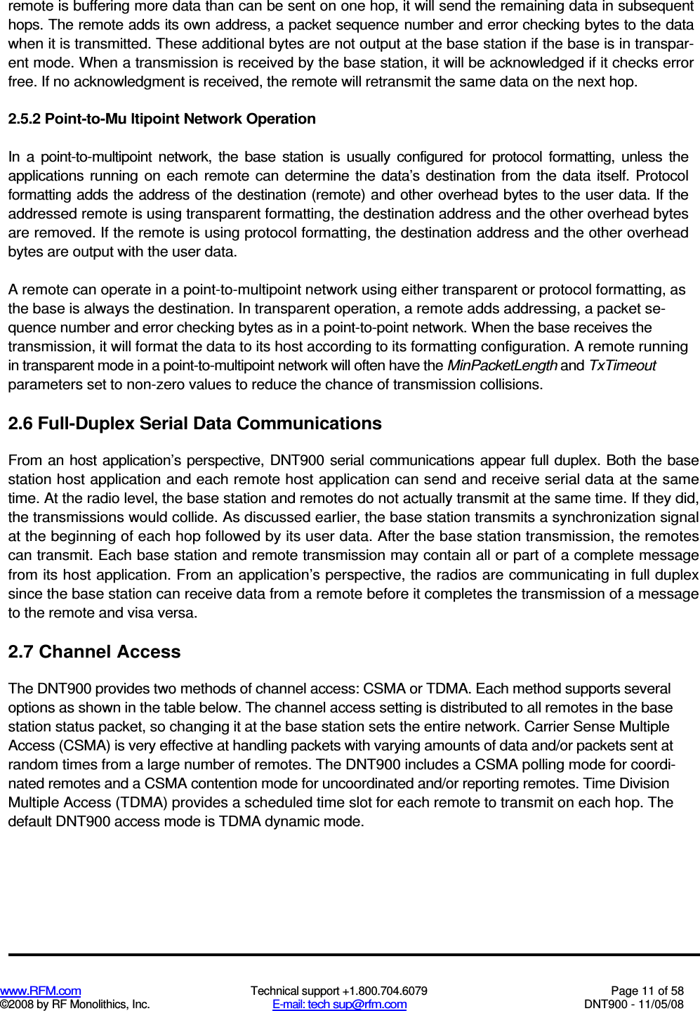
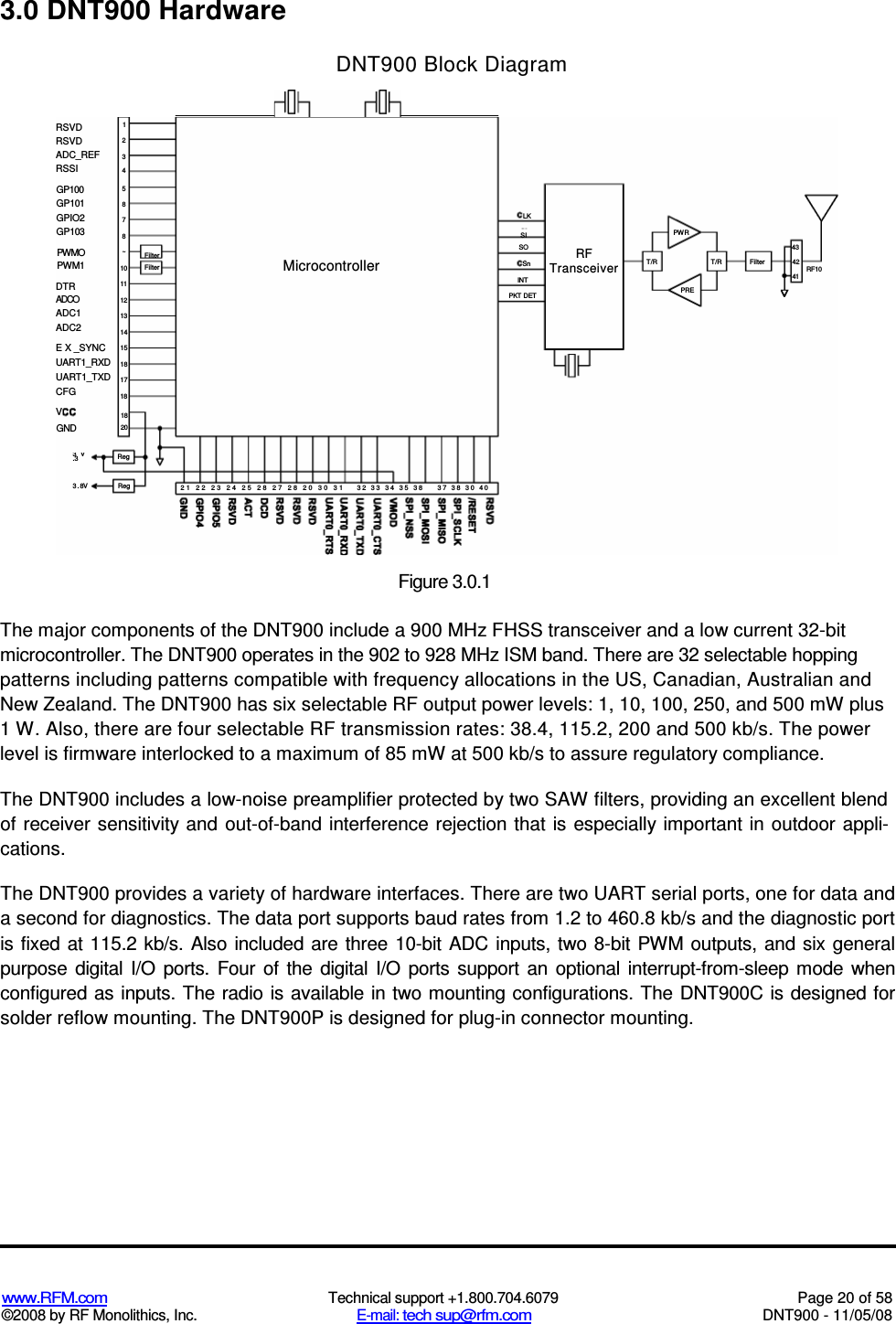
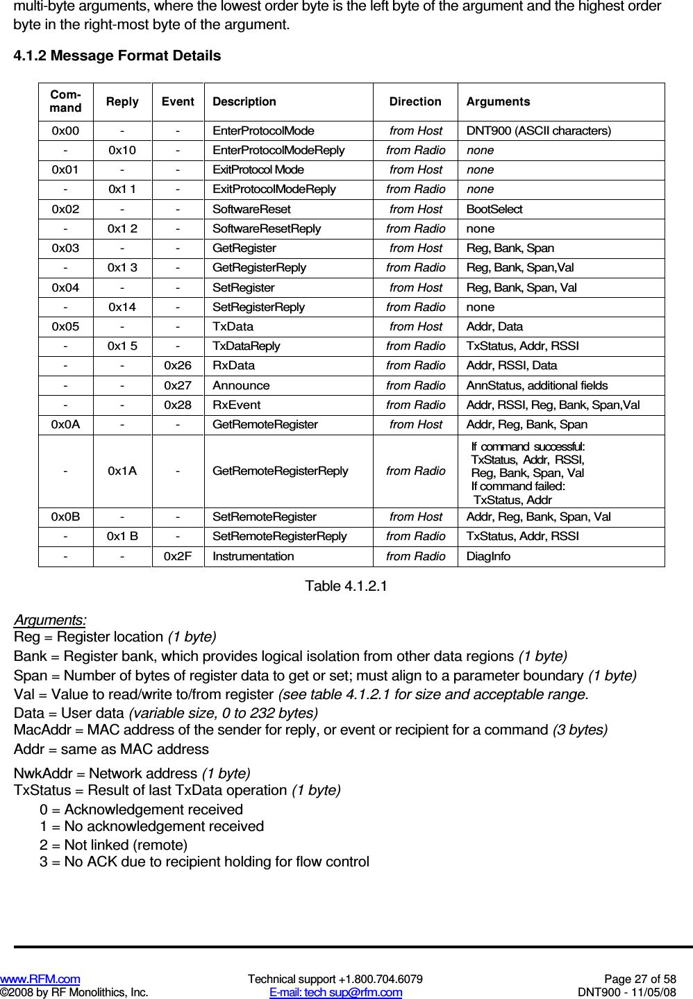
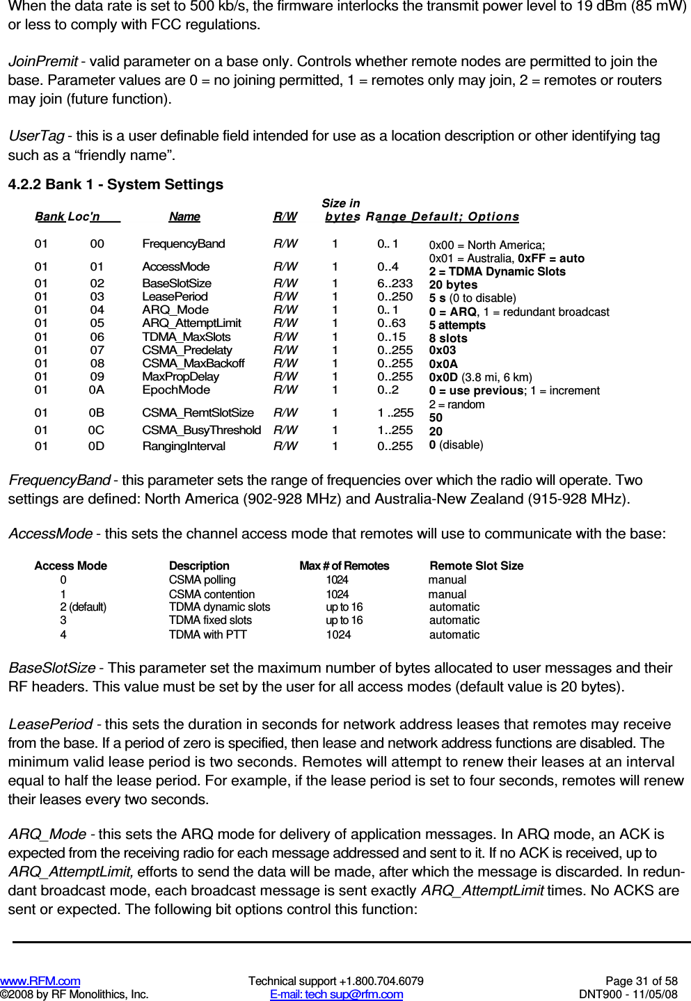
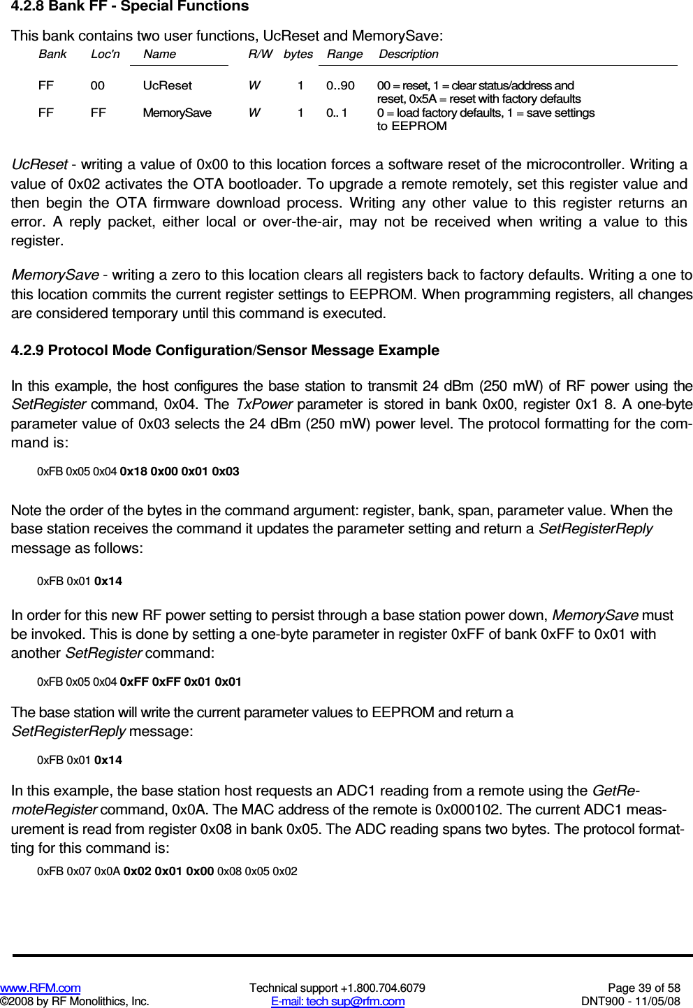
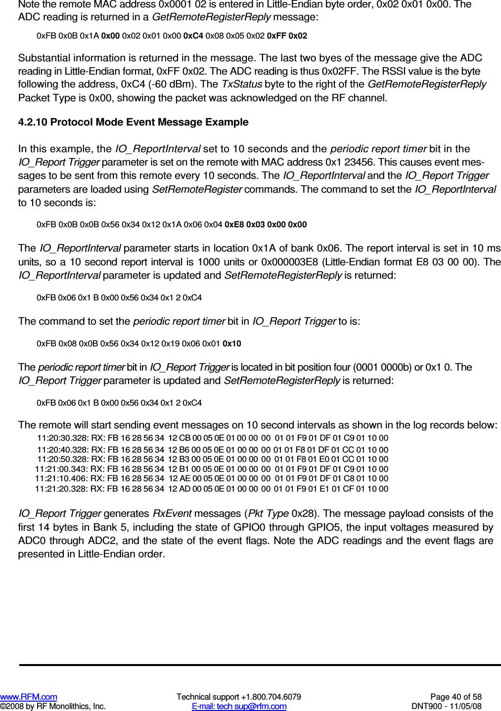
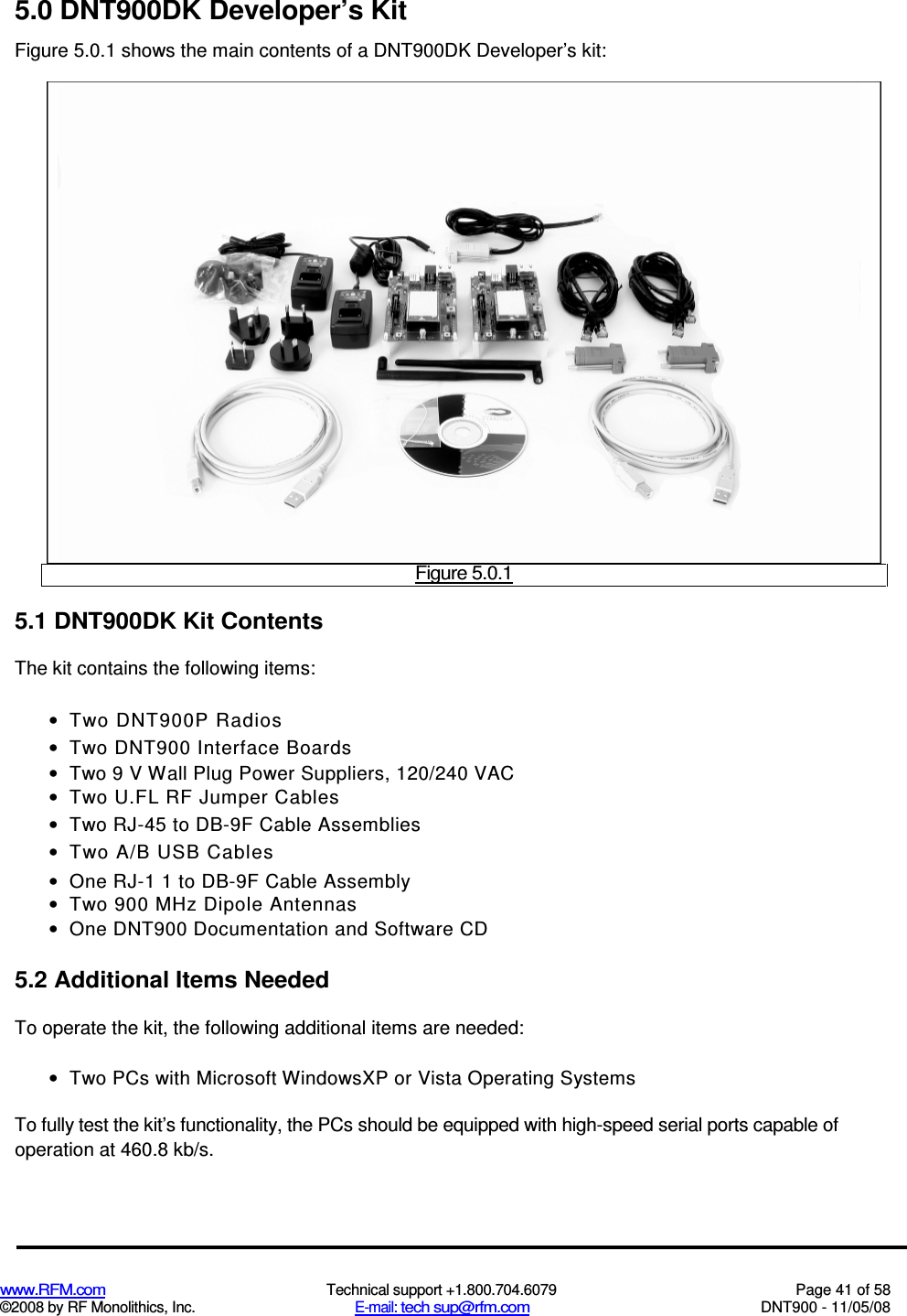
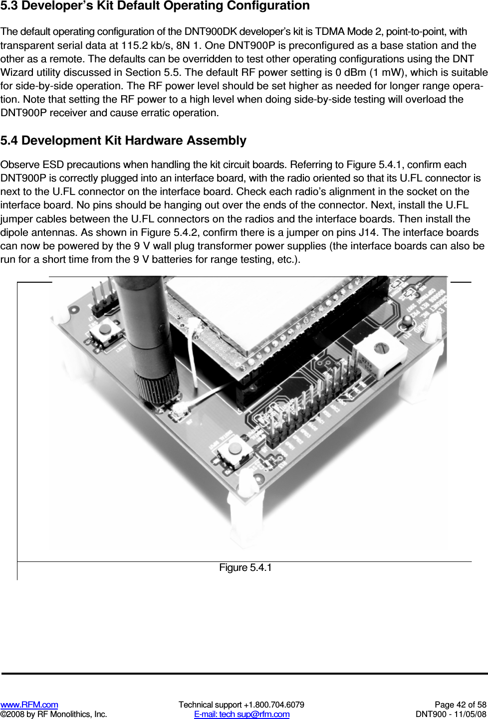
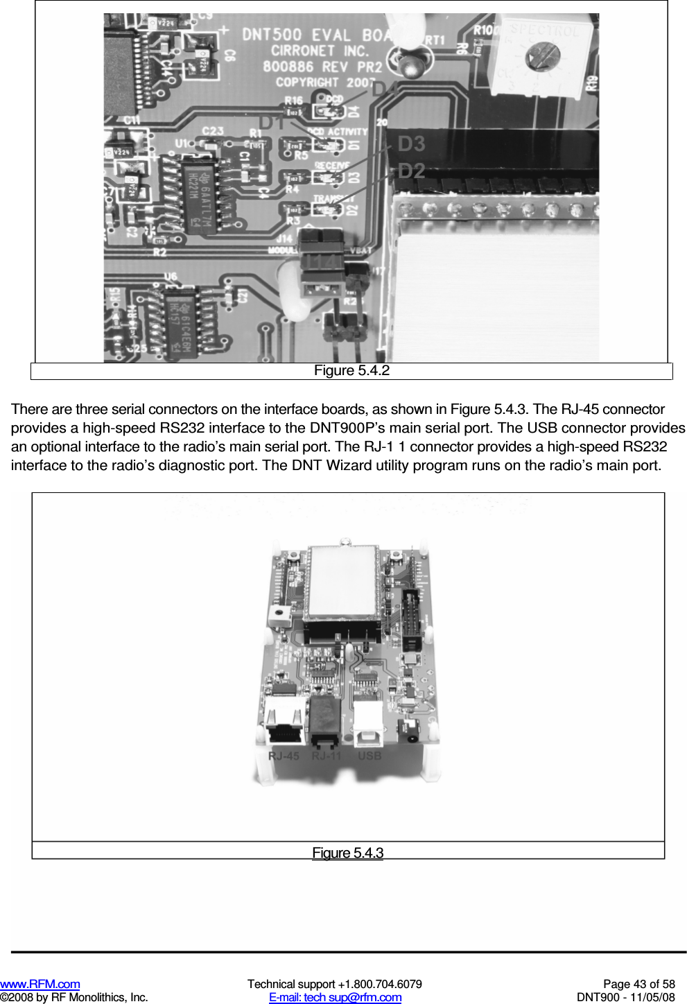
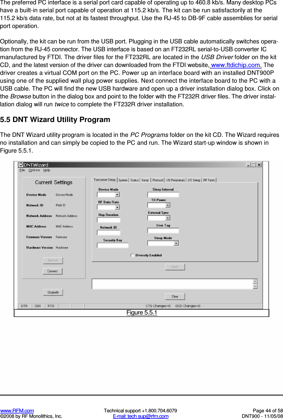
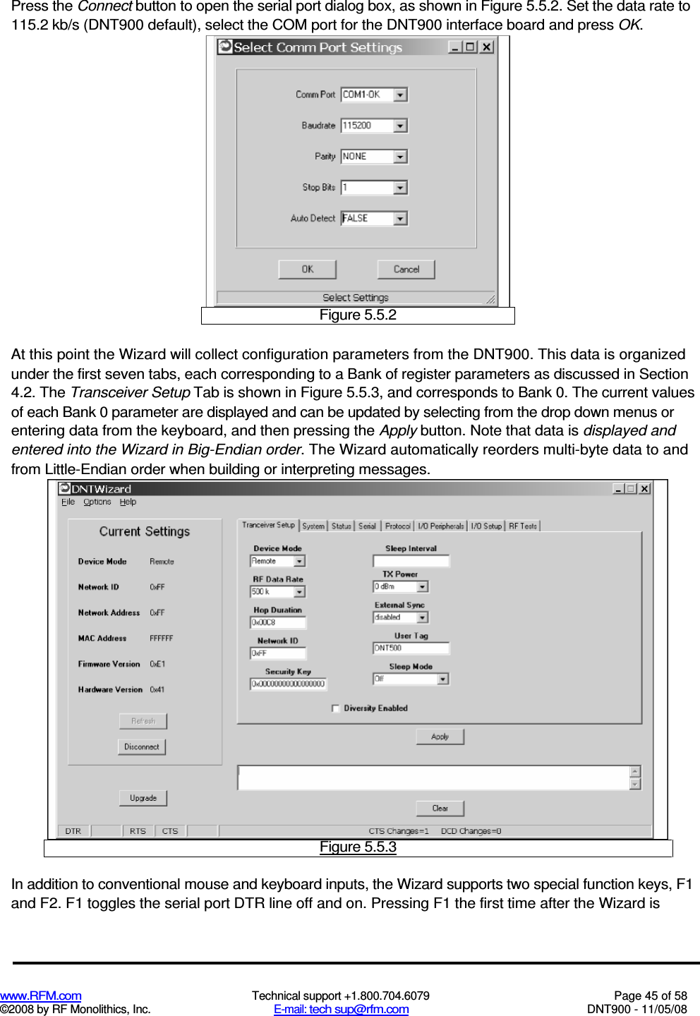
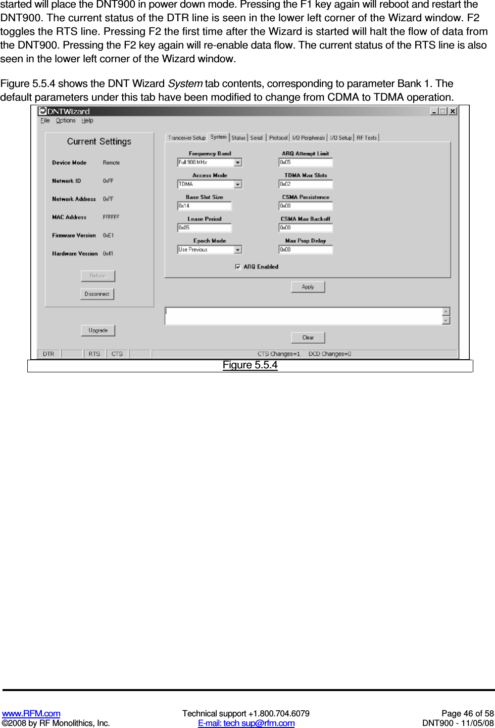
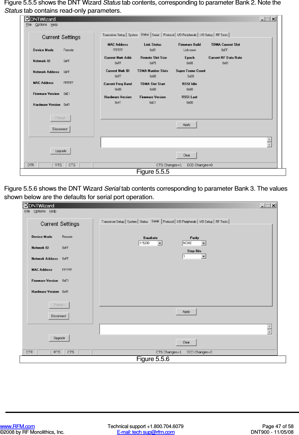
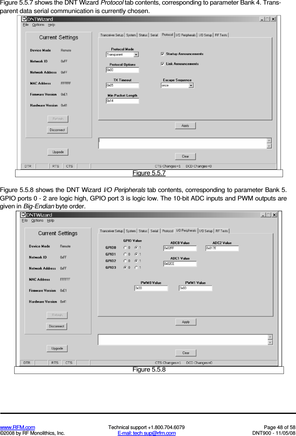
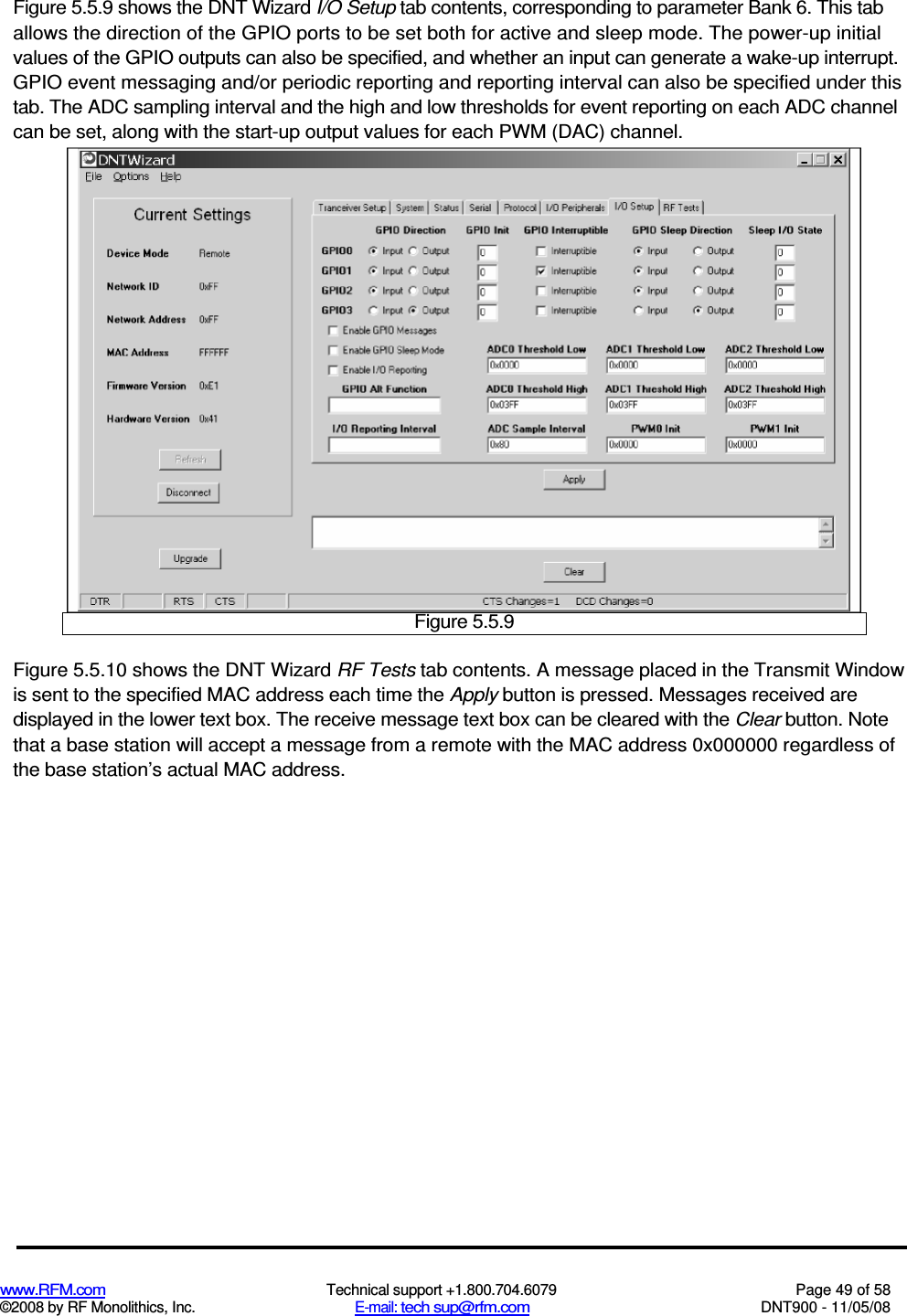
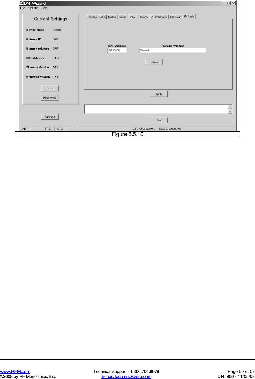
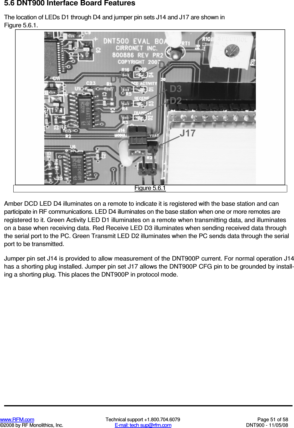
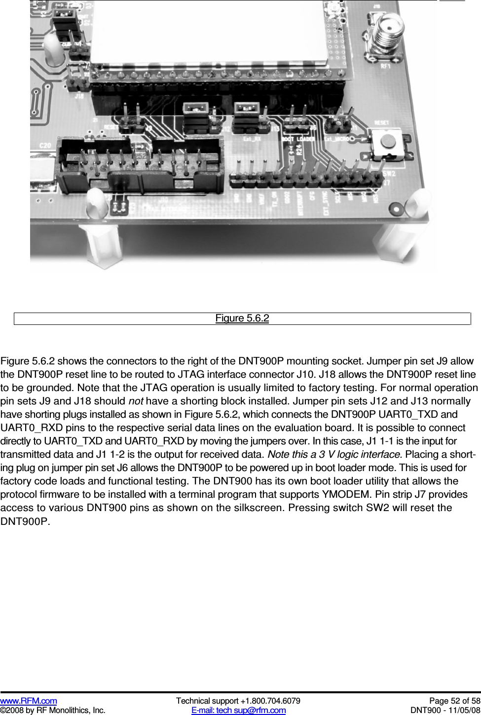
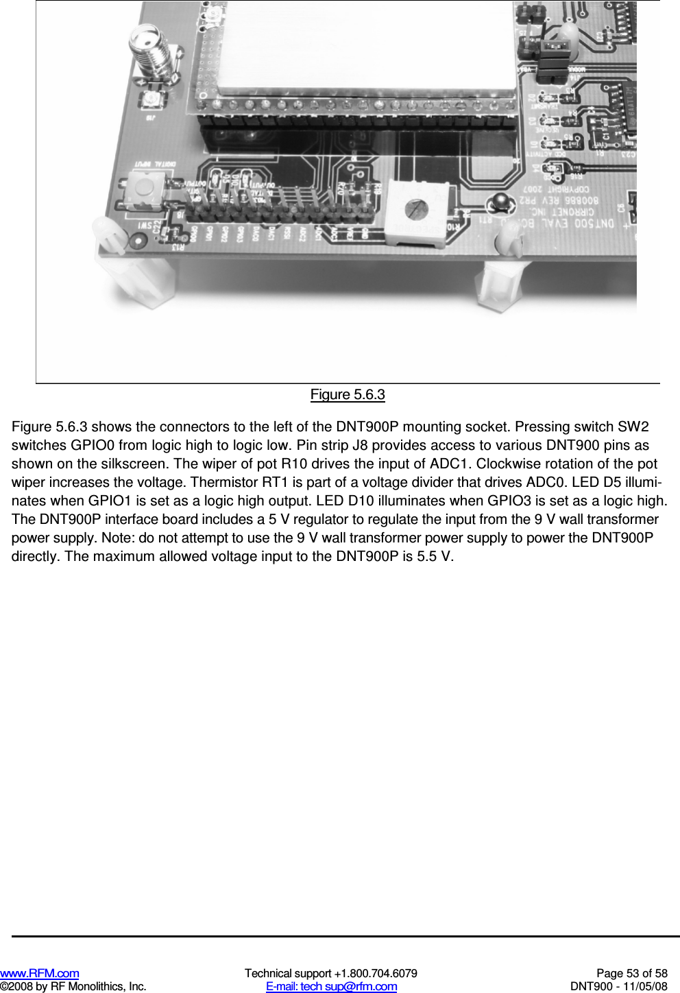
![www.RFM.com Technical support +1.800.704.6079 Page 30 of 58 ©2008 by RF Monolithics, Inc. E-mail: tech sup@rfm.com DNT900 - 11/05/08 RF_DataRate - this sets the over-the-air RF data rate. DNT900’s with different RF data rates cannot intercommunicate. The following codes are defined: 0x00 = 500 kb/s 0x01 = 200 kb/s 0x02 = 115.2 kb/s 0x03 = 38.4 kb/s 0xff = auto (default) A setting of "auto" will cause a remote to scan all 4 possible RF rates for a network to join. A base set to "auto" will run at the maximum rate of 500 kb/s. A change to this setting on the base will trigger a reboot of the network. HopDuration - this sets the duration of the hop frame. The duration is set as a 12-bit value, 0.05 ms/count. InitialNwkID - selects the initial network ID that the radio will start (if a base) or join (if a remote). A value of 0xFF instructs a remote to operate in 'promiscuous mode' and join any network it finds (if set for a base, this will select the default network of 0x00.) The network ID also sets the base frequency at which the hopping pattern starts, as illustrated by the following equation: FrequencyIndex[n] = HoppingPattern[n + 2*NetworkID mod 32] This allows the user to coordinate frequency spacing of co-located networks to maintain a constant sepa-ration as they hop. SecurityKey - this sets the 128-bit AES encryption key that will be used. The intent is for this to act like a password that all radios in the network are configured with. To protect the key, this is a write-only parame-ter for the user (always reads back as 0x2A). Refer to the Section 2.11 for further information. SleepMode - this parameter enables sleep mode, which may be used in conjunction with the automatic I/O reporting feature to wake up on specified triggers. Sleep mode is only available for remotes, and the channel access mode for the network must be one of the CSMA modes. WakeResponse Time - this parameter sets the length of time that a remote in sleep mode will wait for a response after sending an I/O report before going back to sleep, from a minimum of 10 ms to a maximum of 2.5 seconds in 10 ms units. This time interval is set to allow the base host application to respond to a remote with a packet before the remote returns to sleep. If this parameter is set to 0, the remote will stay awake indefinitely after sending an I/O report. WakeLinkTimeout - this parameter sets the maximum length of time that a remote in sleep mode will spend trying to acquire a link to its base station before going back to sleep, from a minimum of 100 ms to 25.5 s in 100 ms units. If this value is set to 0, the remote will stay awake and continue trying to link to its base station indefinitely. TxPower - Sets the transmit power level: 0 = 0 dBm or 1 mW (default) 1 = 10 dBm or 10 mW 2 = 20 dBm or 100 mW 3 = 24 dBm or 250 mW 4 = 27 dBm or 500 mW 5 = 30 dBm or 1000 mW (1 W)](https://usermanual.wiki/Murata-Electronics-North-America/DNT900.User-Manual/User-Guide-1443393-Page-31.png)