Murata Electronics North America DNT900 900 MHz Spread Spectrum Wireless Transceiver User Manual
Murata Electronics North America 900 MHz Spread Spectrum Wireless Transceiver
Contents
- 1. Manual
- 2. User Manual
User Manual

5015 B.U. Bowman Drive Buford, GA 30518 USA Voice: 770-831-8048 Fax: 770-831-8598
Certification Exhibit
FCC ID: HSW-DNT900
IC: 4492A-DNT900
FCC Rule Part: 15.247
IC Radio Standards Specification: RSS-210
ACS Report Number: 08-0361 - 15C
Manufacturer: Cirronet Inc.
Model: DNT900C, DNT900P
Manual
www.RFM.com
Technical support +1.800.704.6079 Page 1 of 58
©2008 by RF Monolithics, Inc. E-mail:
tech sup@rfm.com
DNT900 - 11/05/08
DNT900 Series
900 MHz Spread Spectrum Wireless
Industrial Transceivers
Integration Guide

www.RFM.com
Technical support +1.800.704.6079 Page 2 of 58
©2008 by RF Monolithics, Inc. E-mail:
tech sup@rfm.com
DNT900 - 11/05/08
Important Regulatory Information
FCC ID: HSW-DNT900
IC: 4492A-DNT900
THIS DEVICE COMPLIES WITH PART 15 OF THE FCC RULES. OPERATION IS SUBJECT TO THE
FOLLOWING TWO CONDITIONS. (1) THIS DEVICE MAY NOT CAUSE HARMFUL INTERFERENCE,
AND (2) THIS DEVICE MUST ACCEPT ANY INTERFERENCE RECEIVED, INCLUDING INTERFERENCE
THAT MAY CAUSE UNDESIRED OPERATION.
This Class B digital apparatus complies with Canadian ICES-003.
Cet appareil numérique de la classe B est conforme à la norme NMB-003 du Canada.
FCC User Information
“NOTE: This equipment has been tested and found to comply with the limits for a Class B digital device,
pursuant to Part 15 of the FCC Rules. These limits are designed to provide reasonable protection against
harmful interference in a residential installation. This equipment generates, uses, and can radiate radio
frequency energy and, if not installed and used in accordance with the instructions, may cause harmful
interference to radio communications. However, there is no guarantee that interference will not occur in a
particular installation. If this equipment does cause harmful interference to radio or television reception,
which can be determined by turning the equipment off and on, the user is encouraged to try to correct the
interference by one or more of the following measures:
• Reorient or relocate the receiving antenna.
• Increase the separation between the equipment and receiver.
• Connect equipment to an outlet on a circuit different in which the receiver is connected.
• Consult the dealer or an experienced radio/TV technician for help.”
Warning: Changes or modifications to this device not expressly approved by RFM Inc.
could void the user’s authority to operate the equipment.
RF Exposure
In accordance with FCC requirements of human exposure to radiofrequency fields, the radiating element
shall be installed such that a minimum separation distance of 23cm shall be maintained from the user
and/or general population.
Industry Canada
This Class B digital apparatus meets all requirements of the Canadian Interference Causing Equipment
Regulations. Operation is subject to the following two conditions: (1) this device may not cause harmful
interference, and (2) this device must accept any interference received, including interference that may
cause undesired operation.
Cet appareillage numérique de la classe B répond à toutes les exigences de l'interférence canadienne
causant des règlements d'équipement. L'opération est sujette aux deux conditions suivantes: (1) ce
dispositif peut ne pas causer l'interférence nocive, et (2) ce dispositif doit accepter n'importe quelle
interférence reçue, y compris l'interférence qui peut causer l'opération peu désirée.

www.RFM.com
Technical support +1.800.704.6079 Page 3 of 58
©2008 by RF Monolithics, Inc. E-mail:
tech sup@rfm.com
DNT900 - 11/05/08
“To reduce potential radio interference to other users, the antenna type and its gain should be
so chosen that the equivalent isotropically radiated power (e.i.r.p.) is not more than that
permitted for successful communication.”
“This device has been designed to operate with the antennas listed below, and having a
maximum gain of 6 dBi. Antennas not included in this list or having a gain greater than 6 dBi
are strictly prohibited for use with this device. The required antenna impedance is 50 ohms.”
Cushcraft S8963B 5 dBi gain dipole
Astron 918-2 6 dBi gain yagi
OEM Installation and Compliance Labeling
The DNT900 module is labeled with its own FCC ID number, and, if the FCC ID is not visible
when the module is installed inside another device, then the outside of the device into which the
module is installed must also display a label referring to the enclosed transmitter module.
This exterior label can use wording such as the following:
“Contains Transmitter Module FCC ID: HSW-DNT900” or
“Contains FCC ID: HSW-DNT900”
Any similar wording that expresses the same meaning may be used. The Grantee may either
provide such a label, an example of which must be included in the application for equipment
authorization, or, must provide adequate instructions along with the module which explain this
requirement. In the latter case, a copy of these instructions must be included in the application for
equipment authorization.
The antenna connections from the module to the certain antennas approved with this device are not
unique and require Professional installation.
See section 3.8 of this manual for regulatory notices and labeling requirements. Changes or modifications
to a DNT900 not expressly approved by RFM may void the user’s authority to operate the module.

www.RFM.com
Technical support +1.800.704.6079 Page 4 of 58
©2008 by RF Monolithics, Inc. E-mail:
tech sup@rfm.com
DNT900 - 11/05/08
Table of Contents
1.0 Introduction ........................................................................................................................................... 5
1.1 Why Spread Spectrum?.................................................................................................................................... 5
1.2 Frequency Hopping versus Direct Sequence..........................................................................................6
2.0 DNT900 Radio Operation ......................................................................................................... 7
2.1 Network Synchronization and Registration........................................................................................ 7
2.2 Transparent and Protocol Serial Port Modes..........................................................................................8
2.3 RF Data Communications........................................................................................................................ 8
2.4 RF Transmission Error Control ......................................................................................................... 9
2.5 Network Configurations .................................................................................................................... 9
2.5.1 Point-to-Point Network Operation.................................................................................................. 9
2.5.2 Point-to-Multipoint Network Operation ....................................................................................... 10
2.6 Full-Duplex Serial Data Communications ...................................................................................... 10
2.7 Channel Access ................................................................................................................................ 10
2.7.1 CSMA Modes..................................................................................................................... 11
2.7.2 TDMA Modes ...........................................................................................................................12
2.8 Network Configuration Planning ..................................................................................................... 13
2.9 Serial Port Operation ...................................................................................................................... 15
2.10 Sleep Modes...................................................................................................................................... 16
2.11 Encryption................................................................................................................................................ 18
3.0 DNT900 Hardware............................................................................................................. 19
3.1 Specifications ............................................................................................................................................20
3.2 Module Interface.......................................................................................................................................21
3.3 Input Voltages ...........................................................................................................................................22
3.4 ESD and Transient Protection .................................................................................................................22
3.5 Interfacing to 5 V Logic Systems .............................................................................................................23
3.6 Power-On Reset Requirements ..............................................................................................................23
3.7 Mounting and Enclosures ...............................................................................................................................23
3.8 Connecting Antennas......................................................................................................................................23
3.9 Labeling and Notices .......................................................................................................................................24
4.0 Protocol Messages........................................................................................................................25
4.1 Protocol Message Formats.............................................................................................................................25
4.1.1 Message Types ....................................................................................................................................25
4.1.2 Message Format Details.............................................................................................................. 26
4.1.2 Escape Sequence ..................................................................................................................................27
4.1.3 CFG Select Pin .......................................................................................................................................27
4.1.4 Flow Control .................................................................................................................................... 27
4.1.5 Protocol Mode Data Message Example .............................................................................................28
4.2 Configuration Registers ............................................................................................................................28
4.2.1 Bank 0 - Transceiver Setup..................................................................................................................28
4.2.2 Bank 1 - System Settings............................................................................................................. 30
4.2.3 Bank 2 - Status Registers ............................................................................................................ 31
4.2.4 Bank 3 - Serial.......................................................................................................................................33
4.2.5 Bank 4 - Host Protocol Settings ................................................................................................. 34
4.2.6 Bank 5 - I/O Peripheral Registers ........................................................................................................35
4.2.7 Bank 6 - I/O Setup........................................................................................................................................36
4.2.8 Bank FF - Special Functions ................................................................................................................38
4.2.9 Protocol Mode Configuration/Sensor Message Example.................................................................38
4.2.10 Protocol Mode Event Message Example............................................................................................39

www.RFM.com
Technical support +1.800.704.6079 Page 5 of 58
©2008 by RF Monolithics, Inc. E-mail:
tech sup@rfm.com
DNT900 - 11/05/08
5.0
DNT900DK Developer’s Kit ................................................................................................................
40
5.1
DNT900DK Kit Contents................................................................................................................
40
5.2
Additional Items Needed ...............................................................................................................
40
5.3
Developer’s Kit Default Operating Configuration ..........................................................................
41
5.4
Development Kit Hardware Assembly...........................................................................................
41
5.5
DNT900 Wizard Utility Program ....................................................................................................
43
5.6
DNT900 Interface Board Features ................................................................................................
50
6.0
Demonstration Procedure ...................................................................................................................
53
7.0
Troubleshooting ..................................................................................................................................
54
8.0
Appendices .........................................................................................................................................
55
8.1
Ordering Information......................................................................................................................
55
8.2
Technical Support..........................................................................................................................
55
8.3
DNT900 Mechanical Specifications...............................................................................................
56
9.0
Warranty..............................................................................................................................................
58

www.RFM.com
Technical support +1.800.704.6079 Page 6 of 58
©2008 by RF Monolithics, Inc. E-mail:
tech sup@rfm.com
DNT900 - 11/05/08
1.0 Introduction
The DNT900 series transceivers provide highly reliable wireless connectivity for either point-to-point or
point-to-multipoint applications. Frequency hopping spread spectrum (FHSS) technology ensures maxi-
mum resistance to multipath fading and robustness in the presence of interfering signals, while operation
in the 900 MHz ISM band allows license-free use in the US, Canada, Australia and New Zealand. The
DNT900 supports all standard serial data rates for host communications from 1.2 to 460.8 kb/s. On-board
data buffering and an error-correcting air protocol provide smooth data flow and simplify the task of inte-
gration with existing applications. Key DNT900 features include:
• Multipath fading resistant frequency hop-
ping technology with up to 50 frequency
channels (902 to 928 MHz).
• Support for point-to-point or point-to-
multipoint applications.
• FCC 15.247 certified for license-free
operation.
• 40 mile plus range with omni-directional
antennas (antenna height dependent).
• Transparent ARQ protocol with data
buffering ensures data integrity
1.1 Why Spread Spectrum?
• Selectable 1, 10, 100, 250, 500 or 1000 mW
transmit power with a firmware interlock of
85 mW maximum for 500 kb/s operation.
• Optional AES encryption provides
protection to eavesdropping
• Nonvolatile memory stores DNT900 configu-
ration when powered off
• Dynamic TDMA slot assignment that maxi-
mizes throughput.
• Simple serial interface handles both data and
control at up to 460.8 kb/s
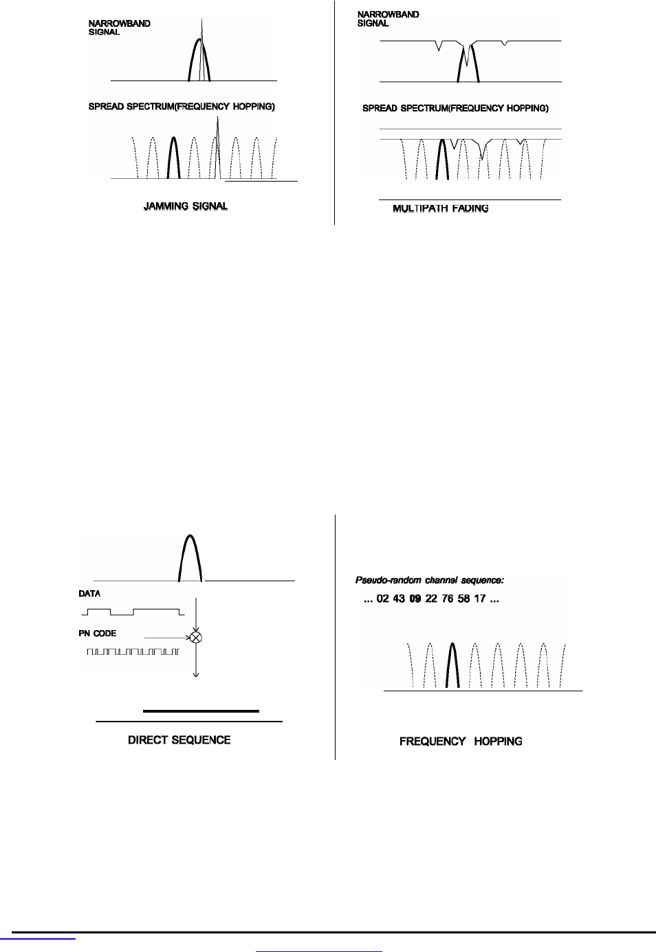
A radio channel can be very hostile, corrupted by noise, path loss and interfering transmissions from
other radios. Even in an interference-free environment, radio performance faces serious degradation
through a phenomenon known as multipath fading. Multipath fading results when two or more reflected
rays of the transmitted signal arrive at the receiving antenna with opposing phases, thereby partially or
completely canceling the signal. This problem is particularly prevalent in indoor installations. In the fre-
quency domain, a multipath fade can be described as a frequency-selective notch that shifts in location
and intensity over time as reflections change due to motion of the radio or objects within its range. At any
given time, multipath fades will typically occupy 1% - 2% of the band. From a probabilistic viewpoint, a
conventional radio system faces a 1% - 2% chance of signal impairment at any given time due to multi-
path fading.
Spread spectrum reduces the vulnerability of a radio system to interference from both multipath fading
and jammers by distributing the transmitted signal over a larger region of the frequency band than would
otherwise be necessary to send the information. This allows the signal to be reconstructed even though
part of it may be lost or corrupted in transmission.
www.RFM.com
Technical support +1.800.704.6079 Page 7 of 58
©2008 by RF Monolithics, Inc. E-mail:
tech sup@rfm.com
DNT900 - 11/05/08
Narrow-band versus spread-spectrum transmission
Figure 1.1.1
1.2 Frequency Hopping versus Direct Sequence
The two primary approaches to spread spectrum are direct sequence spread spectrum (DSSS) and
frequency hopping spread spectrum (FHSS), either of which can generally be adapted to a given applica-
tion. Direct sequence spread spectrum is produced by multiplying the transmitted data stream by a much
faster, noise-like repeating pattern. The ratio by which this modulating pattern exceeds the bit rate of the
base-band data is called the processing gain, and is equal to the amount of rejection the system affords
against narrow-band interference from multipath and jammers. Transmitting the data signal as usual, but
varying the carrier frequency rapidly according to a pseudo-random pattern over a broad range of chan-
nels produces a frequency hopping spectrum system.
Forms of spread spectrum - direct sequence and frequency hopping
Figure 1.1.2

www.
RFM.com
Technical support +1.800.704.6079 Page 8 of 58
©2008 by RF Monolithics, Inc. E-mail:
tech sup@rfm.com
DNT900 - 11/05/08
One disadvantage of direct sequence systems is that due to spectrum constraints and the design difficul-
ties of broadband receivers, they generally employ only a minimal amount of spreading, typically no more
than the minimum required by the regulating agencies. For this reason, the ability of DSSS systems to
overcome fading and in-band jammers is relatively weak. By contrast, FHSS systems are capable of
probing the entire band as necessary to find a channel free of interference. This means that a FHSS
system will degrade gracefully as the channel gets noisier, while a DSSS system may exhibit uneven
coverage or work well until a certain point and then give out completely.
Because it offers greater immunity to interfering signals, FHSS is often the preferred choice for co-located
systems. Since direct sequence signals are very wide, they tend to offer few non-overlapping channels,
whereas multiple hoppers may interleave with less interference. Frequency hopping does carry some
disadvantage in that as the transmitter cycles through the hopping pattern it is nearly certain to visit a few
blocked channels where no data can be sent. If these channels are the same from trip to trip, they can be
memorized and avoided. Unfortunately, this is generally not the case, as it may take several seconds to
completely cover the hop sequence during which time the multipath delay profile may have changed
substantially. To ensure seamless operation throughout these outages, a hopping radio must be capable
of buffering its data until a clear channel can be found. A second consideration of frequency hopping
systems is that they require an initial acquisition period during which the receiver must lock on to the
moving carrier of the transmitter before any data can be sent, which typically takes several seconds. In
summary, frequency hopping systems generally feature greater coverage and channel utilization than
comparable direct sequence systems. Of course, other implementation factors such as size, cost, power
consumption and ease of implementation must also be considered before a final radio design choice can
be made.
DNT900 series modules achieve regulatory certification under FHSS rules at air data rates of 38.4, 115.2
and 200 kb/s. At 500 kb/s, the DNT900 series modules achieve regulatory certification under “digital
modulation” or DTS rules. At 500 kb/s DNT900 series modules still employ frequency hopping to mitigate
the effects of interference and multipath fading, but hop on fewer, more widely spaced frequencies than at
lower data rates.
2.0 DNT900 Radio Operation
2.1 Network Synchronization and Registration
As discussed above, frequency hopping radios such as the DNT900 periodically change the frequency at
which they transmit. In order for the other radios in the network to receive the transmission, they must be
listening to the frequency on which the current transmission is being sent. To do this, all the radios in the
network must be synchronized to the same hopping pattern.
In point-to-point or point-to-multipoint networks, one radio module is designated as the base station. All
other radios are designated as remotes. One of the responsibilities of the base station is to transmit a
synchronization signal to the remotes to allow them to synchronize with the base station. Since the re-
motes know the hopping pattern, once they are synchronized with the base station, they know which
frequency to hop to and when. Every time the base station hops to a different frequency, it immediately
transmits a synchronizing signal.
When a remote is powered on, it rapidly scans the frequency band for the synchronizing signal. Since the
base station is transmitting on up to 50 frequencies and the remote is scanning up to 50 frequencies, it
can take several seconds for a remote to synchronize with the base station.

www.
RFM.com
Technical support +1.800.704.6079 Page 9 of 58
©2008 by RF Monolithics, Inc. E-mail:
tech sup@rfm.com
DNT900 - 11/05/08
Once a remote has synchronized with the base station, it will request registration information to allow it to
join the network. Registration can be handled automatically by the base station, or it can be controlled by
allowing the base station host application to authenticate the remote for registration. When a remote is
registered, it receives several network parameters from the base station, including HopDuration, InitialN-
wkID, FrequencyBand and Nwk_Key (see Section 4.2 for parameter details). Note that if a registration
parameter is changed at the base station, it will update the parameter in the remotes over the air.
Among other things, registration allows the tracking of remotes entering and leaving a network, up to a
limit of 254 remotes. The base station builds a table of serial numbers of registered remotes using their
three-byte serial numbers (MAC addresses). To detect if a remote has gone offline or out of range, the
registration is “leased” must be “renewed” once every 250 hops. Any transmission from a remote running
on a leased registration will renew its lease with the base station.
2.2 Transparent and Protocol Serial Port Modes
DNT900 radios can work in two serial port data modes: transparent and packet protocol. Transparent
mode formatting is simply the raw user data. Protocol mode formatting includes a start of packet framing
character, length byte, addressing, command bytes, etc. Transparent mode operation is especially useful
in point-to-point systems that act as simple cable replacements. In point-to-multipoint systems where the
base station needs to send data specifically to each remote, protocol formatting must be used. Protocol
formatting is also required for configuration commands and responses, and sensor I/O commands and
responses. Protocol formatting details are covered in Section 4.
The DNT900 provides two ways to switch between transparent and protocol modes. If CFG input Pin 18
on the DNT900 is switched from logic high to low, protocol mode is invoked. Or if the ASCII escape
sequence “DNT900” is sent (without quotation marks) to the primary serial input following at least a 20 ms
pause in data flow, the DNT900 will switch to the protocol mode. When input Pin 18 is switched from logic
low to high, or an ExitProtocolMode command is sent to the primary serial input, the DNT900 will switch
to transparent operation. Note that if the escape sequence is used to switch to protocol mode, the se-
quence will be transmitted before protocol mode is invoked.
When operating in transparent mode, two configuration parameters control when a DNT900 radio will
send the data in its transmit buffer. The MinPacketLength parameter sets the minimum number of bytes
that must be present in the transmit buffer to trigger a transmission. The TxTimeout parameter sets the
maximum time data in the transmit buffer will be held before transmitting it, even if the number of data
bytes is less than MinPacketLength. The default value for both the MinPacketLength and the TxTimeout
parameters is zero, so that any bytes that arrive in the DNT900 transmit buffer will be sent on the next
hop. As discussed in Section 2.5.2, it is useful to set these parameters to non-zero values in point-to-
multipoint systems where some or all the remotes are in transparent mode.
2.3 RF Data Communications
At the beginning of each hop, the base station transmits a synchronizing signal. After the synchronizing
signal is sent, the base will transmit any user data in its transmit buffer, unless in transparent mode the
MinPacketLength and/or TxTimeout parameters have been set to non-zero. The maximum amount of
data that the base station can transmit per hop is limited by the BaseSlotSize parameter, which has a
maximum value of 233 bytes. If there is no user data or reception acknowledgements (ACKs) to be sent
on a hop, the base station will only transmit the synchronization signal.

www.RFM.com
Technical support +1.800.704.6079 Page 10 of 58
©2008 by RF Monolithics, Inc. E-mail:
tech sup@rfm.com
DNT900 - 11/05/08
The operation for remotes is similar to the base station, but without the synchronizing signal. The Re-
moteSlotSize parameter sets the maximum number of bytes a remote can transmit on one hop, up to a
limit of 243 bytes per hop. The RemoteSlotSize must be coordinated with the HopDuration and BaseSlot-
Size parameters and the number of registered remotes. The MinPacketLength and TxTimeout parame-
ters operate in a remote in the same manner as in the base station.
2.4 RF Transmission Error Control
The DNT900 supports two error control modes: automatic transmission repeats (ARQ), and redundant
transmissions for broadcast packets from the base station. In both modes, the radio will detect and dis-
card any duplicates of messages it receives so that the host application will only receive one copy of a
given packet. In the redundant transmission mode, broadcast packets are repeated a fixed number of
times based on the value of the ARQ_AttemptLimit parameter. In ARQ mode, a packet is sent and an
acknowledgement is expected on the next hop. If an acknowledgement is not received, the packet is
transmitted again on the next available hop until either an ACK is received or the maximum number of
attempts is exhausted. If the ARQ_AttemptLimit parameter is set to its maximum value, a packet trans-
mission will be retried without limit until the packet is acknowledged. This is useful in some point-to-point
cable replacement applications where it is important that data truly be 100% error-free, even if the desti-
nation remote goes out of range temporarily.
2.5 Network Configurations
The DNT900 supports two network configurations: point-to-point and point-to-multipoint. In a point-to-
point network, one radio is set up as the base station and the other radio is set up as a remote. In a point-
to-multipoint network, a star topology is used with the radio set up as a base station acting as the central
communications point and all other radios in the network set up as remotes. In this configuration, each
communication takes place between the base station and one of the remotes. Remotes cannot communi-
cate directly with each other. It should be noted that point-to-point operation is a subset of the point-to-
multipoint operation, so there is no need to specify one or the other.
2.5.1 Point-to-Point Network Operation
Most point-to-point networks act as serial cable replacements and both the base station and the remote
use transparent mode. Unless the MinPacketLength and TxTimeout parameters have been set to non-
zero, the base station will send the data in its transmit buffer on each hop, up to a limit controlled by the
BaseSlotSize parameter. In transparent mode, if the base station is buffering more data than can be sent
on one hop, the remaining data will be sent on subsequent hops. The base station adds the address of
the remote, a packet sequence number and error checking bytes to the data when it is transmitted. These
additional bytes are not output at the remote in transparent mode. The sequence number is used in
acknowledging successful transmissions and in retransmitting corrupted transmissions. A two-byte CRC
and a one-byte checksum allows a received transmission to be checked for errors. When a transmission
is received by the remote, it will be acknowledged if it checks error free. If no acknowledgment is re-
ceived, the base station will retransmit the same data on the next hop. Note that acknowledgements from
remotes are suppressed on broadcast packets from the base station.
In point-to-point operation, by default a remote will send the data in its transmit buffer on each hop, up to
the limit controlled by its RemoteSlotSize parameter. If desired, the MinPacketLength and TxTimeout
parameters can be set to non-zero values, which configures the remote to wait until the specified amount
of data is available or the specified delay had expired before transmitting. In transparent mode, if the

www.RFM.com
Technical support +1.800.704.6079 Page 11 of 58
©2008 by RF Monolithics, Inc. E-mail:
tech sup@rfm.com
DNT900 - 11/05/08
remote is buffering more data than can be sent on one hop, it will send the remaining data in subsequent
hops. The remote adds its own address, a packet sequence number and error checking bytes to the data
when it is transmitted. These additional bytes are not output at the base station if the base is in transpar-
ent mode. When a transmission is received by the base station, it will be acknowledged if it checks error
free. If no acknowledgment is received, the remote will retransmit the same data on the next hop.
2.5.2 Point-to-Mu ltipoint Network Operation
In a point-to-multipoint network, the base station is usually configured for protocol formatting, unless the
applications running on each remote can determine the data’s destination from the data itself. Protocol
formatting adds the address of the destination (remote) and other overhead bytes to the user data. If the
addressed remote is using transparent formatting, the destination address and the other overhead bytes
are removed. If the remote is using protocol formatting, the destination address and the other overhead
bytes are output with the user data.
A remote can operate in a point-to-multipoint network using either transparent or protocol formatting, as
the base is always the destination. In transparent operation, a remote adds addressing, a packet se-
quence number and error checking bytes as in a point-to-point network. When the base receives the
transmission, it will format the data to its host according to its formatting configuration. A remote running
in transparent mode in a point-to-multipoint network will often have the MinPacketLength and TxTimeout
parameters set to non-zero values to reduce the chance of transmission collisions.
2.6 Full-Duplex Serial Data Communications
From an host application’s perspective, DNT900 serial communications appear full duplex. Both the base
station host application and each remote host application can send and receive serial data at the same
time. At the radio level, the base station and remotes do not actually transmit at the same time. If they did,
the transmissions would collide. As discussed earlier, the base station transmits a synchronization signal
at the beginning of each hop followed by its user data. After the base station transmission, the remotes
can transmit. Each base station and remote transmission may contain all or part of a complete message
from its host application. From an application’s perspective, the radios are communicating in full duplex
since the base station can receive data from a remote before it completes the transmission of a message
to the remote and visa versa.
2.7 Channel Access
The DNT900 provides two methods of channel access: CSMA or TDMA. Each method supports several
options as shown in the table below. The channel access setting is distributed to all remotes in the base
station status packet, so changing it at the base station sets the entire network. Carrier Sense Multiple
Access (CSMA) is very effective at handling packets with varying amounts of data and/or packets sent at
random times from a large number of remotes. The DNT900 includes a CSMA polling mode for coordi-
nated remotes and a CSMA contention mode for uncoordinated and/or reporting remotes. Time Division
Multiple Access (TDMA) provides a scheduled time slot for each remote to transmit on each hop. The
default DNT900 access mode is TDMA dynamic mode.
www.RFM.com
Technical support +1.800.704.6079 Page 12 of 58
©2008 by RF Monolithics, Inc. E-mail:
tech sup@rfm.com
DNT900 - 11/05/08
Access Mode
Description
Max Number of Remotes
Slot Size
0 CSMA polling 1024 manual
1 CSMA contention 1024 manual
2 TDMA dynamic slots up to 16 automatic
3 TDMA fixed slots up to 16 automatic
4 TDMA with PTT up to 16 automatic
Table 2.7.1
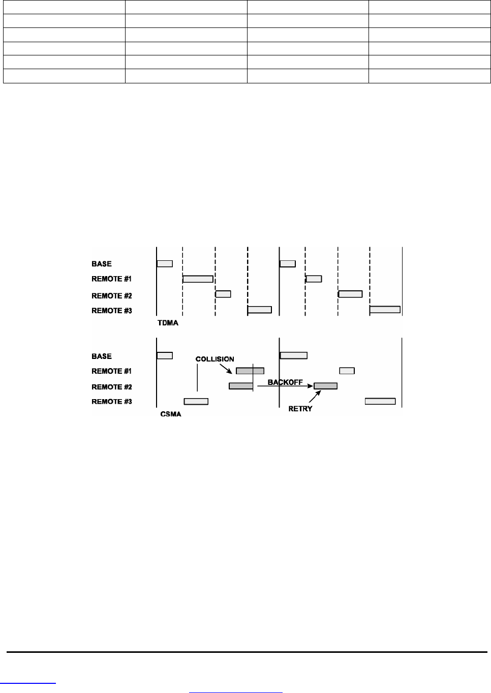
2.7.1 CSMA Modes
When using CSMA, each remote with data to send listens to see if the channel is clear and then trans-
mits. If the channel is not clear, a remote will wait a random period of time and listen again. CSMA works
best when a large or variable number of remotes transmit infrequent bursts of data. There is no absolute
to the number of remote radios that can be supported in this mode. For a DNT900 network, a maximum
of 254 remotes can be supported if base station join-leave tracking is required, or a maximum of 1024
remotes is suggested if base station join-leave tracking is not required. Figure 2.7.1 .1 below compares
TDMA to CSMA operation.
TDMA and CSMA operation
Figure 2.7.1.1
There are two important parameters related to CSMA operation. The CSMA _MaxBackoff parameter
defines the maximum time that a remote will wait after a collision before attempting to send the packet
again (back-off interval). The CSMA_ Predelay parameter controls the maximum time that a remote will
randomly backoff when it finds the channel available before transmitting.
CSMA polling (Mode 0) - is used for point-to-point systems and point-to-multipoint systems where only
one remote at a time can receive data to transmit (ModBus, etc.). Since only one remote will attempt to
transmits at a time, the CSMA_Predelay parameter is ignored on the first transmission attempt and no
predelay is used for minimum latency. This mode provides maximum throughput since there is no conten-
tion between remotes and the entire portion of the hop frame following the base station transmission is
available for a remote to transmit. The user can set CSMA_MaxBackoff, BaseSlotSize and RemoteSlot-
Size parameters when using this mode. Note that a CSMA_Delay parameter setting of 0x00 would lead to
collisions if more than one remote tried to transmit. Applications where more than one remote can receive

www.RFM.com
Technical support +1.800.704.6079 Page 13 of 58
©2008 by RF Monolithics, Inc. E-mail:
tech sup@rfm.com
DNT900 - 11/05/08
serial data to transmit at a time, or where periodic reporting and/or event reporting are enabled should not
use this mode.
CSMA Contention (Mode 1) - provides classical CSMA channel access, and gives the user control over
both the CSMA_MaxBackoff and CSMA_Predelay parameters. This mode is well-suited for large num-
bers of uncoordinated remotes, and/or where periodic/event reporting is used. In addition to CSMA_
MaxBackoff and CSMA_Predelay, the user can set the BaseSlotSize and RemoteSlotSize parameters
when using this mode. The following guidelines are suggested for setting CSMA_Predelay:
For lightly loaded CSMA contention networks, decrease CSMA_Predelay
to 0x20 or less to reduce latency.
For heavily loaded CSMA contention networks, increase CSMA_Predelay
to 0x80 or more for better throughput.
As an option, the CSMA modes allow the base station to directly track remotes entering and leaving the
network for up to 254 remotes. The base station is operated in protocol mode and is configured to gener-
ate a CONNECT message for its host when a remote registers, and a DISCONNECT message when the
remote’s registration lease expires.
The base station in a CSMA network can generate CONNECT messages for more than 254 remotes.
This allows the host application to track remotes entering and leaving a large CSMA network by creating
a table of MAC addresses and periodically sending a GetRemoteRegister command to each remote in
the table. Failure to answer a GetRemoteRegister command indicates the remote is no longer active in
the network.
CSMA modes work well in many applications, but CSMA has some limitations, as summarized below:
Bandwidth is not guaranteed to any remote.
Marginal RF links to some remotes can create a relatively high chance of
collisions in heavily loaded networks.
2.7.2 TDMA Modes
The TDMA modes provide guaranteed bandwidth to some or all of the remotes in the network. Remotes
that register with the base station receive several special parameters, including ranging information and a
specific channel access slot assignment. TDMA registrations are always leased and must be renewed
every 250 hops. The DNT900 provides three different modes of TDMA access, as discussed below.
TDMA Dynamic Slots (Mode 2) - is used for general-purpose TDMA applications where scaling the
capacity per slot to the number of active remotes is automatic. Each remote that registers with the base
receives an equal time slice. As new remotes join, the size of the TDMA slots shrink accordingly. The
number of slots, individual slot start times, and the RemoteSlotSize are computed automatically by the
DNT900 network in this mode. The user should note that the bandwidth to each remote will change
immediately as remotes join and leave the network. When running in protocol mode, care must be taken
not to format packets too long to be sent in a single hop due to automatic RemoteSlotSize reduction.
TDMA Fixed Slots (Mode 3) - is used for applications that have fixed data throughput requirements, such
as isochronous voice or streaming telemetry. The slot start time and the RemoteSlotSize are computed
automatically by the DNT900 network in this mode. The user must set the number of slots.

www.RFM.com
Technical support +1.800.704.6079 Page 14 of 58
©2008 by RF Monolithics, Inc. E-mail:
tech sup@rfm.com
DNT900 - 11/05/08
TDMA with PTT (Mode 4) supports remotes with a "push-to-talk" feature, also referred to as "listen-
mostly" remotes. This mode uses fixed slot allocations. Remotes can be registered for all but the last slot.
The last slot is reserved for the group of remotes that are usually listening, but occasionally need to
transmit. In essence, the last slot is a shared channel for this group of remotes. When one of them has
data to send it keys its transmitter much like a walkie-talkie, hence the name push-to-talk (PTT).
The slot start time and the RemoteSlotSize are computed automatically by the DNT900 network in this
mode. The user must specify the number of slots. The last slot is reserved for the PTT remotes. The user
must configure PTT remotes individually to select Mode 4 operation. The network makes no guarantee
that PTT remote transmissions will not collide in the shared slot. The user's application must ensure that
no more than one PTT remote at a time is using the slot.
2.8 Network Configuration Planning
Some planning is necessary for a DNT900 network to coordinate the RF_DataRate, HopDuration, Bas-
eSlotSize, RemoteSlotSize, MinPacketLength, TxTimeout and TDMA_MaxNumSlots parameters to
achieve a practical configuration. This is true even for modes that automatically compute some of these
parameters. Each parameter has a limited range of usable values, as shown in the Table 2.8.1 below:
Parameter Useable Range Value
RF_DataRate
0..3 500, 200, 115.2 and 38.4 kb/s
HopDuration
40..4095 2. .204.75 ms (0.05 ms/count)
TDMA_MaxNumSlots
1 ..16 max number of TDMA slots (MNS) for remotes
BaseSlotSize
6..233 max number of user data bytes transmitted per hop
RemoteSlotSize
3..243 max number of user data bytes transmitted per hop
MinPacketLength
0..255 0. .255 bytes
Tx Timeout
0..255 0. .255 ms (1 ms/count)
Table 2.8.1
The highest RF data rate, 500 kb/s, provides the highest throughput and the most flexibility with respect
to the other parameters. The maximum RF power that can be used at 500 kb/s is 85 mW. The three lower
data rates can run up to 1 W of RF power, and the receiver becomes progressively more sensitive as the
data rate is lowered. So for greatest range, one of the three lower RF data rates should be used.
The maximum DNT900 HopDuration setting is about 200 ms regardless of the RF data rate chosen. For a
given data rate, FHSS operation tends to become more robust as hop duration is reduced. However,
running with a shorter hop duration may require setting the BaseSlotSize and RemoteSlotSize parame-
ters well below their maximum values at the lower RF data rates. The equation below calculates the
minimum hop duration needed at a given RF data rate for a specific number of remote slots and Base-
SlotSize and RemoteSlotSize parameter settings. Support for optimizing a DNT900 configuration for a
specific application is also available from RFM’s Technical Support Group. See Section 10.3. for technical
support contact information.
www.RFM.com
Technical support +1.800.704.6079 Page 15 of 58
©2008 by RF Monolithics, Inc. E-mail:
tech sup@rfm.com
DNT900 - 11/05/08
The minimum required hop duration for a DNT900 configuration is:
T
HD
= T
BRO
+
NRS*TRO
+
TRFB*(BBSS
+ N
RS
*
B
RSS
)
Where:
T
HD
is the minimum required hop duration in milliseconds
T
BRO
is the base and registration request overhead time for each hop (RF data rate dependent)
N
RS
is the number of remote slots
T
RO
is the remote overhead time for each hop (RF data rate dependent)
T
RFB
is the transmission time for one user byte (RF data rate dependent)
B
BSS
is the
BaseSlotSize
parameter in bytes
B
RSS
is the
RemoteSlotSize
parameter in bytes
The constants in the equation for each RF data rate are given in the following table:
RF Data Rate kb/s T
BRO
ms T
RO
ms T
RFB
ms
38.40 11.620 4.817 0.2080
115.2 4.953 2.039 0.0694
200 3.540 1.450 0.0400
500 2.388 0.970 0.0160
Table 2.8.2
For example, consider a point-to-point CSMA Mode 0 system operating at 38.4 kb/s with the BaseSlot-
Size parameter set to 133 bytes and the RemoteSlotSize parameter set to 128 bytes. The minimum hop
duration needed to support one-hop transmissions of full slot size messages in both directions for this
configuration is:
= 11.620 + 1*4.817 + 0.2080*(133 + 1*128)
= 16.437 + 0.2080*261
= 70.725 ms
The closest programmable hop duration is 70.750 ms.
It should be noted that the base station operating system will commandeer 5 bytes from the BaseSlotSize
allocation in Mode 0 and up to 13 bytes in Mode 1 to send reception acknowledgements (ACKs) back to
the remotes. The BaseSlotSize should be sized accordingly. In the above example, the BaseSlotSize
parameter is set five bytes larger than the RemoteSlotSize parameter to accommodate the ACK bytes.
When running a point-to-multipoint network with uncoordinated remotes using CSMA Mode 1, it is useful
to set
N
RS
to a value of 3 or higher in the equation. Although CSMA does not create reserved time slots
for remotes, extending the hop duration this way allows several uncoordinated transmissions of user data
and/or periodic/event reports to arrive in the same slot with a relatively few collisions.
The performance of a CSMA Mode 1 system can often be helped by setting the MinPacketLength and
TxTimeout parameters on any remotes running transparent mode to non-zero values, especially if host
messages only contain a few bytes each and transmission latency is not critical. For starting point values,
set the MinPacketLength equal to one-half the RemoteSlotSize and TxTimeout to at least three times the
hop duration. This will help avoid excessive transmission collisions due to having many packets transmit-
ted, each carrying only a small amount of user data on top of the relatively large packet overhead

www.RFM.com
Technical support +1.800.704.6079 Page 16 of 58
©2008 by RF Monolithics, Inc. E-mail:
tech sup@rfm.com
DNT900 - 11/05/08
structure. As an example, consider a TDMA Mode 2 or 3 system operating at 500 kb/s. Up to 10 regis-
tered remotes need to be accommodated. A BaseSlotSize of 138 bytes is needed, and each remote
needs enough slot time to support a RemoteSlotSize of 64 bytes. The minimum hop duration needed to
support this configuration is:
= 2.388 + 10*0.970 + 0.0160*(138 + 10*64)
= 12.088 + 0.0160*778
= 24.536 ms
The closest programmable hop duration is 24.550 ms.
In all TDMA modes, the base station operating system will commandeer one byte from the BaseSlotSize
allocation for each registered remote to send ACKs to the remotes. The BaseSlotSize and MinPacket-
Length should be sized accordingly.
2.9 Serial Port Operation
DNT900 networks are often used for wireless communication of serial data. The DNT900 supports serial
baud rates from 1.2 to 460.8 kb/s. Listed in the table below are the supported data rates and their related
byte data rates and byte transmission times for an 8N1 serial port configuration:
Baud Rate kb/s Byte Data Rate kB/s Byte Transmission Time ms
1.2 0.12 8.3333
2.4 0.24 4.1667
4.8 0.48 2.0833
9.6 0.96 1.0417
19.2 1.92 0.5208
38.4 3.84 0.2604
115.2 11.52 0.0868
230.4 23.04 0.0434
460.8 46.08 0.0217
Table 2.9.1
To support continuous full-duplex serial port data flow, an RF data rate much higher than the serial port
baud rate is required for FHSS. Radios transmissions are half duplex, and there are overheads related to
hopping frequencies, assembling packets from the serial port data stream, transmitting them, sending
ACK’s to confirm error-free reception, and occasional transmission retries when errors occur.
For example, consider a CSMA Mode 0 transparent data system operating at 500 kb/s with the Bas-
eSlotSize parameter set to 133 bytes (128 bytes net after the five byte allocation for sending ACKs) and
the RemoteSlotSize parameters set to 128 bytes. The minimum hop duration needed to efficiently support
this configuration is:
= 2.388 + 1*0.970 + 0.0160*(133 +1*128)
= 3.358 + 0.01 60*261
= 7.534 ms

www.RFM.com
Technical support +1.800.704.6079 Page 17 of 58
©2008 by RF Monolithics, Inc. E-mail:
tech sup@rfm.com
DNT900 - 11/05/08
Setting the hop duration to 7.55 ms, the average full-duplex serial port byte rate that can be supported
under error free conditions is:
128 Bytes /7.55 ms = 16.942 kB/s, or 169.42 kb/s for 8N1
Continuous full-duplex serial port data streams at a baud rate of 115.2 k/bs can be supported by this
configuration, provided only occasional RF transmission errors occur. Plan on an average serial port data
flow of 75% of the calculated error-free capacity for general-purpose applications, and 50% of the calcu-
lated error-free capacity for RF challenging applications such as vehicle telemetry and heavy industrial
process environments.
Most applications do not require continuous serial port data flow. The DNT900 transmit and receive
buffers hold at least 1024 bytes and will accept brief bursts of data at high baud rates, provided the aver-
age serial port data flow such as shown in the example above is not exceeded. It is strongly recom-
mended that the DNT900 host use hardware flow control. The host must send no more than 32 bytes
additional bytes to the DNT900 when the DNT900 de-asserts the host’s CTS line. In turn, the DNT900 will
send no more than one byte following the host de-asserting its RTS line. Three-wire serial port operation
is allowed by connecting the DNT900 CTS output to its RTS input. However, three-wire operation should
be limited to applications that send small bursts of data occasionally at an average serial port data flow
less than 50% of the calculated error-free capacity. Data loss is possible under adverse RF channel
conditions when using three-wire serial operation.
2.10 Sleep Modes
To save power in applications where a remote transmits infrequently, the DNT900 supports a hardware
sleep mode. Hardware sleep mode is entered by switching DTR Pin 11 on the DNT900 from logic low to
high. While in hardware sleep mode, the DNT900 consumes less than 0.5 mA. This mode allows a
DNT900 to be powered off while its host device remains powered. After leaving hardware sleep mode
(Pin 11 low to high), the radio must re-synchronize with the base station and re-register.
In addition to the sleep mode controlled by the DTR pin, in CSMA mode the DNT900 remotes support an
additional sleep mode to support battery-powered applications. When this mode is enabled, the DNT900
is in a low-power state and only wakes up in response to the I/O report triggers. The following list explains
the rules that sleeping remotes follow:
The DNT900 will wake up when any of the enabled I/O report trigger conditions fire. When any of
the ADC triggers are enabled, the radio will also wake up every ADC_SampleIntvl long enough to
sample the ADCs, and then go back to sleep.
When a sleeping radio wakes up, it must acquire and synchronize to its base before it can send
or receive any data. To prevent excessive battery use, if the remote is unable to acquire before
the WakeLinkTimeout elapses, it will cancel any pending event trigger(s) and go back to sleep.
If a remote is linking for the first time or if its last attempt to acquire and synchronize was unsuc-
cessful, it will scan and record the entire broadcast system parameter list before it goes back to
sleep. Otherwise, in order to conserve battery life, a sleeping remote will update any values that it
may hear while it is awake, but is not required to listen to the entire list.

www.RFM.com
Technical support +1.800.704.6079 Page 18 of 58
©2008 by RF Monolithics, Inc. E-mail:
tech sup@rfm.com
DNT900 - 11/05/08
•
If a remote is linking for the first time or if its last attempt to acquire and synchronize was unsuc-
cessful, it will send a registration request to the base, allowing it to announce its presence to the
host. Otherwise, in order to conserve battery life, a sleeping remote will not register each time it
reacquires link with its base on successive wakeups.
• After a remote has received an acknowledgement for its I/O report (assuming it is successful), a
WakeResponse Time
timer is started before the remote goes back to sleep. This allows the base
host time to send a message to the remote. Note that the only notification that the base host ap-
plication has that a remote is awake is its report packet. In order to send it data, the base host
must ensure that the message is transmitted and received before the remote's
WakeRespon-
seTime
window elapses. If this function is not needed, the
WakeResponse Time
can be set to
zero to disabled it.
The lease renewal mechanism is not supported for sleeping remotes. In order to successfully use sleep-
ing remotes, the user must ensure that the system is configured for CSMA mode and that leases are
disabled. If these settings are not used, there is no guarantee that the remotes will be able to communi-
cate reliably. Because leases are not supported, there is no built-in mechanism for the base to detect or
announce to its host if a remote stops making its I/O reports, is powered down, or otherwise leaves the
network.
To summarize, while a remote is awake, the following list of condition checks are used to determine if and
when it is allowed to go back to sleep:
• If the remote is linking for the first time or was unsuccessful linking on its last attempt, it will re-
main awake to record the beacon system parameter list.
• At wakeup, the
WakeLinkTimeout
timer is started. If the remote is unable to acquire link before
this elapses, it goes back to sleep.
• If the remote receives an acknowledgement for a data packet it has sent (typically an Event
packet, but in theory could be any other type of message), it starts or resets the
WakeRespon-
seTime
timer to remain awake.
• So long as a GPIO for which edge triggered I/O reporting is enabled remains in its asserted state,
the remote will remain awake.
• The remote will remain awake while it still has any ARQ attempts left for a queued transmit
packet of any type.
• The remote will remain awake while it is has serial characters in its buffer left to transmit to its lo-
cal host, plus whatever time is required for the last transmitted character to clear the RXD pin.
Sleep functions are controlled by the following registers (see Section 4.2):
SleepMode
- enables/disables sleep mode.
WakeResponse Time
- sets the amount of time that a remote will wait for a
response after sending an I/O report.
WakeLinkTimeout
- sets the maximum time that a remote will spend trying
to acquire it base before giving up.

www.RFM.com
Technical support +1.800.704.6079 Page 19 of 58
©2008 by RF Monolithics, Inc. E-mail:
tech sup@rfm.com
DNT900 - 11/05/08
Sleep is also affected by the following registers associated with I/O reporting:
IO_ReportTrigger,
IO_ReportInterval, ADC_SampleIntvl,
and
GPIO_Edge Trigger.
The following table indicates how the
status and control pins function on sleeping remotes:
Pin Awake Sleep
RTS Normal operation Hi-Z
CTS Normal operation 0 V
DCD Normal operation 0 V
ACTIVITY 3 V 0 V
EXT_SYNC Not supported Not supported
DIVERSITY Normal operation 0 V
TXD Normal operation Hi-Z
RXD Normal operation 0 V
Table 2.10.1
Note that the Activity pin may be used by a local host to detect when a sleeping remote is awake. The
behavior of the GPIOs during sleep is governed by the
GPIO_ SleepMode
,
GPIO_SleepDir
, and
GPIO_SleepState
configuration registers. Refer to the register definitions in Section 4.2.
2.11 Encryption
The DNT900 supports optional 128-bit AES encryption of data and configuration packets. Encryption is
enabled by setting the
EncryptionKey
register to a value other than all zeros (all zeros is a flag that en-
cryption is disabled). A remote without encryption enabled cannot link to an encrypted base, and an
encrypted remote will not attempt to link to an unencrypted base. If a remote's encryption key does not
match that of the base, it can link but not exchange data. The
EncryptionKey
register can be set over-the
air so it can be changed periodically if desired.
www.RFM.com
Technical support +1.800.704.6079 Page 20 of 58
©2008 by RF Monolithics, Inc. E-mail:
tech sup@rfm.com
DNT900 - 11/05/08
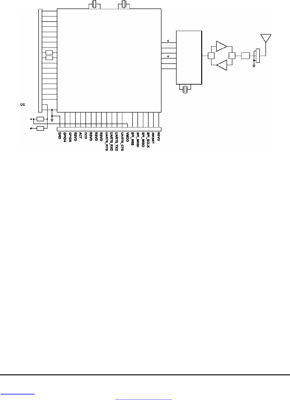
3.0 DNT900 Hardware
DNT900 Block Diagram
The major components of the DNT900 include a 900 MHz FHSS transceiver and a low current 32-bit
microcontroller. The DNT900 operates in the 902 to 928 MHz ISM band. There are 32 selectable hopping
patterns including patterns compatible with frequency allocations in the US, Canadian, Australian and
New Zealand. The DNT900 has six selectable RF output power levels: 1, 10, 100, 250, and 500 mW plus
1 W. Also, there are four selectable RF transmission rates: 38.4, 115.2, 200 and 500 kb/s. The power
level is firmware interlocked to a maximum of 85 mW at 500 kb/s to assure regulatory compliance.
The DNT900 includes a low-noise preamplifier protected by two SAW filters, providing an excellent blend
of receiver sensitivity and out-of-band interference rejection that is especially important in outdoor appli-
cations.
The DNT900 provides a variety of hardware interfaces. There are two UART serial ports, one for data and
a second for diagnostics. The data port supports baud rates from 1.2 to 460.8 kb/s and the diagnostic port
is fixed at 115.2 kb/s. Also included are three 10-bit ADC inputs, two 8-bit PWM outputs, and six general
purpose digital I/O ports. Four of the digital I/O ports support an optional interrupt-from-sleep mode when
configured as inputs. The radio is available in two mounting configurations. The DNT900C is designed for
solder reflow mounting. The DNT900P is designed for plug-in connector mounting.
Figure 3.0.1
RSVD
RSVD
ADC_REF
RSSI
DTR
ADCO
ADC1
ADC2
E X _SYNC
UART1_RXD
UART1_TXD
CFG
V
GP100
GP101
GPIO2
GP103
PWMO
PWM1
GND
3 V
.3
3 . 8V
Reg
Reg
10
11
12
13
14
15
18
17
18
18
20
2
3
4
5
8
7
8
~
1
Filter
Filter
21 22 23 24 25 28 27 28 20 30 31
Microcontroller
32 33 34 35 38
37 38 30 40
PWR
43
T/R
T/R
Filter
42
RF10
41
PRE
RF
Transceiver
LK
PKT DET
INT
SI
SO
Sn

www.RFM.com
Technical support +1.800.704.6079 Page 21 of 58
©2008 by RF Monolithics, Inc. E-mail:
tech sup@rfm.com
DNT900 - 11/05/08
3.1 DNT900 Specifications
Characteristic
Sym
Minimum
Typical
Maximum
Units
Operating Frequency Range
902.75
927.25 MHz
Number of Hopping Patterns
32
Hop Dwell Time
5
200 ms
Number of RF Channels
50
Modulation
FSK
RF Data Transmission Rates
38.4, 115.2, 200 and 500 kb/s
Receiver Sensitivity
10
-5
BER @ 38.4 kb/s
-108
dBm
10
-5
BER @ 500 kb/s
-94
dBm
Transmitter RF Output Power Levels
1, 10, 100, 250, 500, 1000 at 38.4 to 200 kb/s
1, 10, 85 at 500 kb/s mW
Optimum Antenna Impedance
50
Ω
RF Connection
DNT900P - U.FL Connector
DNT900C U.FL Connector or PCB Pad
Network Topologies
Point-to-Point, Point-to-Multipoint
Access Schemes
TDMA and CSMA
Number of Network Nodes
TDMA
16
CSMA
1024
ADC Input Range
0
3.3 V
ADC Input Resolution
10
bits
Signal Source Impedance for ADC Reading
10 K
Ω
PWM (DAC) Output Range
0
3.3 V
PWM (DAC) Output Resolution
7 bits
PWM Output Period
20
µs
Primary Serial Port Baud Rates
1.2, 2.4, 4.8, 9.6, 19.2, 38.4, 115.2, 230.4, 460.8
kb/s
Diagnostic Serial Port Baud Rates
115.2 kb/s
Digital I/O:
Logic Low Input Level
-0.5
0.8 V
Logic High Input Level
2
3.3 V
Logic Input Internal Pull-up Resistor
50
200 K
Ω
Logic Input Internal Pull-down Resistor
50
180 K
Ω
Power Supply Voltage Range V
CC
+3.3
+5.5 Vdc
Power Supply Voltage Ripple
10 mV
P-P
Peak Transmit Mode Current
900 mA
Average Operating Current:
Base
105
mA
Remote, No Data Transmission
35
mA
Remote, 9.6 kb/s Continuous
Data Stream
40
mA
Remote, 115.2 kb/s Continuous
Data Stream
53
mA
Sleep Current
50 µA
Operating Temperature Range
-40
85
o
C
Operating Relative Humidity Range
10
90 %
Table 3.1.1

www.RFM.com
Technical support +1.800.704.6079 Page 22 of 58
©2008 by RF Monolithics, Inc. E-mail:
tech sup@rfm.com
DNT900 - 11/05/08
3.2 Module Interface
Electrical connections to the DNT900C are made through the I/O pads and through the I/O pins on the
DNT900P. The hardware I/O functions are detailed in the table below:
Pad
Name
Description
1 RSVD Reserved pad. Leave unconnected.
2 RSVD Reserved pad. Leave unconnected.
3 ADC_REF
ADC supply and external full scale reference voltage input. Voltage range is 2.4 to 3.3 Vdc.
Connect pad 34 to this input to reference the ADC full scale reading to the module’s 3.3 V
regulated supply.
4 RSVD Reserved pad. Leave unconnected.
5 GPIO0
Configurable digital I/O port 0. When configured as an input, an internal pull-up resistor can be
selected and interrupt from sleep can be invoked. When configured as an output, the power-on
state is also configurable.
6 GPIO1 Configurable digital I/O port 1. Same configuration options as GPIO0.
7 GPIO2 Configurable digital I/O port 2. Same configuration options as GPIO0.
8 GPIO3 Configurable digital I/O port 3. Same configuration options as GPIO0.
9 PWM0 Pulse-width modulated output 0 with internal low-pass filter. Filter is 1
st
order, 159 Hz 3 dB BW.
10 PWM1 Pulse-width modulated output 1 with internal low-pass filter. Filter is 1
st
order, 159 Hz 3 dB BW.
11 SLEEP Default functionality is active high module sleep input. When switched low after sleep, the
module executes a power-on reset.
12 ADC0 10-bit ADC input 0. Full scale reading is referenced to the ADC_REF input.
13 ADC1 10-bit ADC input 1. Full scale reading is referenced to the ADC_REF input.
14 ADC2 10-bit ADC input 2. Full scale reading is referenced to the ADC_REF input.
15 RSVD Reserved pad. Leave unconnected.
16 DIAG_TX Diagnostic output (for factory use).
17 DIAG_RX Diagnostic input (for factory use).
18 /CFG
Protocol selection input. Leave unconnected when using software commands to select trans-
parent/protocol mode (default is transparent mode). Logic low selects protocol mode, logic high
selects transparent mode.
19 VCC Power supply input, +3.3 to +5.5 Vdc.
20 GND Power supply and signal ground. Connect to the host circuit board ground.
21 GND Power supply and signal ground. Connect to the host circuit board ground.
22 GPIO4 Configurable digital I/O port 4. When configured as an input, an internal pull-up resistor can be
selected. When configured as an output, the power-on state is configurable.
23 GPIO5 Configurable digital I/O port 5. Same configuration options as GPIO4.
24 RSVD Reserved pad. Leave unconnected.
25 ACT Data activity output, logic high when data is being transmitted or received.
26 /DCD
Default functionality is data carrier detect output, which provides a logic low on a remote when
the module is locked to FHSS hopping pattern and logic low on a base station when at least
one remote is connected to it.

www.RFM.com
Technical support +1.800.704.6079 Page 23 of 58
©2008 by RF Monolithics, Inc. E-mail:
tech sup@rfm.com
DNT900 - 11/05/08
Pad
Name
Description
27 RSVD Reserved pad. Leave unconnected.
28 RSVD Reserved pad. Leave unconnected.
29 RSVD Reserved pad. Leave unconnected.
30 /UART0 _ RTS Default functionality is UART flow control input for the module’s host. A logic low allows data
flow from the module to the host; a logic high blocks data flow from the module to the host.
31 UART0_RXD UART received data output to host from module.
32 UART0_TXD UART host data input to be transmitted by module.
33 /UART0 _ CTS UART flow control output from the module to the host. A logic low should allow data flow
from the host; a logic high should block data flow from the host.
34 VMOD Module’s +3.3 V regulated supply output. Connect to pad 3 to support 3.3 V full scale and/or
ratiometric ADC readings, etc. Current drain on this output should be no greater than 5
mA.
35 RSVD Reserved pad. Leave unconnected.
36 RSVD Reserved pad. Leave unconnected.
37 RSVD Reserved pad. Leave unconnected.
38 RSVD Reserved pad. Leave unconnected.
39 /RESET Active low module hardware reset.
40 RSVD Reserved pad. Leave unconnected.
41 GND RF ground (DNT900CC only). Connect to the host circuit board ground plane.
42 RFIO
Alternate RF port to the U.FL connector (DNT900C only). The antenna can be connected to this
port with a 50 ohm stripline or coaxial cable. Leave unconnected when using the U.FL
connector.
43 GND RF ground (DNT900C only). Connect to the host circuit board ground plane.
Table 3.2.1
3.3 Input Voltages
DNT900 radio modules can operated from an unregulated DC input (Pad/Pin 19) in the range of 3.3
(trough) to 5.5 V (peak) with a maximum ripple of 5% over the temperature range of -40 to 85
o
C.
Apply-
ing AC, reverse DC, or a DC voltage outside the range given above can cause damage and/or create a
fire and safety hazard. Further, care must be taken so logic inputs applied to the radio stay within the
voltage range of 0 to 3.3 V. Signals applied to the analog inputs must be in the range of 0 to ADC_REF
(Pad/Pin 3). Applying a voltage to a logic or analog input outside of its operating range can damage the
DNT900 module.
3.4 ESD and Transient Protection
The DNT900C and DNT900P circuit boards are electrostatic discharge (ESD) sensitive. ESD precautions
must be observed when handling and installing these components. Installations must be protected from
electrical transients on the power supply and I/O lines. This is especially important in outdoor installations,
and/or where connections are made to sensors with long leads.
Inadequate transient protection can result
in damage and/or create a fire and safety hazard.
www.RFM.com
Technical support +1.800.704.6079 Page 24 of 58
©2008 by RF Monolithics, Inc. E-mail:
tech sup@rfm.com
DNT900 - 11/05/08
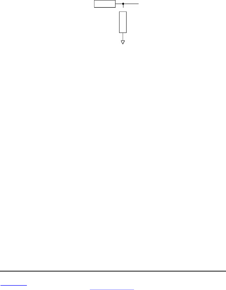
3.5 Interfacing to 5 V Logic Systems
All logic signals including the serial ports on the DNT900 are 3.3 V signals. To interface to 5 V signals, the
resistor divider network shown below must be placed between the 5 V signal outputs and the DNT900
signal inputs. The output voltage swing of the DNT900 3.3 V signals is sufficient to drive 5 V logic inputs.
5V
Logic
DNT500
2.2K
4.3K
Figure 3.5.1
3.6 Power-On Reset Requirements
The DNT900 has an internal reset circuit that generates and maintains the DNT900 in a reset state until
the power supply voltage reaches 3.3 volts for 100 milliseconds. This reset circuit protects the radio and
non-volatile memory from brown-out voltage conditions. If devices that communicate with the DNT900
have shorter reset periods, an allowance must be made to allow the DNT900 to come out of reset. Com-
mands and data sent before the DNT900 is out of reset will be ignored.
3.7 Mounting and Enclosures
DNT900C radio modules are mounted by reflow soldering them to a host circuit board. DNT900P mod-
ules are mounted by plugging their pins into a set of mating connectors on the host circuit board. Refer to
the DNT900 Data Sheet for DNT900P connector details.
DNT900 radio module enclosures must be made of plastics or other materials with low RF attenuation to
avoid compromising antenna performance. Metal enclosures are not suitable as they will block antenna
radiation and reception. Outdoor enclosures must be water tight, such as a NEMA 4X enclosure.
3.8 Connecting Antennas
A U.FL miniature coaxial connector is provided on both DNT900 configurations for connection to the
RFIO port. A short U.FL coaxial cable can be used to connect the RFIO port directly to an antenna. In this
case the antenna should be mounted firmly to avoid stressing the U.FL coaxial cable due to antenna
mounting flexure. Alternately, a U.FL coaxial jumper cable can be used to connect the DNT900 module to
a U.FL connector on the host circuit board. The connection between the host circuit board U.FL connector
and the antenna or antenna connector on the host circuit board should be implemented as a 50 ohm
stripline. The design details of the stripline are covered in the DNT900 Data Sheet.

www.RFM.com
Technical support +1.800.704.6079 Page 25 of 58
©2008 by RF Monolithics, Inc. E-mail:
tech sup@rfm.com
DNT900 - 11/05/08
3.9 Labeling and Notices
DNT900 FCC Certification - The DNT900 hardware has been certified for operation under FCC Part 15
Rules, Section 15.247.
The antenna(s) used for this transmitter must be installed to provide a separation
distance of at least 20 cm from all persons and must not be co-located or operating in conjunction with
any other antenna or transmitter.
DNT900 FCC Notices and Labels -
This device complies with Part 15 of the FCC rules. Operation is
subject to the following two conditions: (1) this device may not cause harmful interference, and (2) this
device must accept any interference received, including interference that may cause undesired operation.
A clearly visible label is required on the outside of the user’s (OEM) enclosure stating that this product
contains a DNT900 transceiver assembly, FCC ID: HSW-DNT900. WARNING: This device operates
under Part 15 of the FCC rules. Any modification to this device, not expressly authorized by RFM, Inc.,
may void the user’s authority to operate this device.
Canadian Department of Communications Industry Notice - IC: 4492A-DNT900
This apparatus complies with Health Canada’s Safety Code 6 / IC RSS 210.
ICES-003
This digital apparatus does not exceed the Class B limits for radio noise emissions from digital apparatus
as set out in the radio interference regulations of Industry Canada.
Le present appareil numerique n’emet pas de bruits radioelectriques depassant les limites applicables
aux appareils numeriques de Classe B prescrites dans le reglement sur le brouillage radioelectrique
edicte par Industrie Canada.

www.RFM.com
Technical support +1.800.704.6079 Page 26 of 58
©2008 by RF Monolithics, Inc. E-mail:
tech sup@rfm.com
DNT900 - 11/05/08
4.0 Protocol Messages
4.1 Protocol Message Formats
The DNT900 is configured and controlled through a series of protocol mode messages. All protocol mode
messages have a common header format:
0 1 2 3 ...
SOP
Length
PktType
variable number of arguments ...
Figure 4.1.1
The scale above is in bytes.
The Start-of-Packet (SOP) character, 0xFB, is used to distinguish the beginning of a message and to
assure synchronization in the event of a glitch on the serial port at startup.
The Length byte is defined as the length of the remainder of the message following the length byte itself
(or the length of the entire message - 2).
The Packet Type (PktType) byte specifies the type of message. It is a bitfield-oriented specifier, decoded
as follows:
Bits 7-6 Reserved for future use
Bit 5 Event - set to indicate this message is an event
Bit 4 Reply - set to indicates this message is a reply
Bits 3-0 Type - indicates the message type/command
As indicated, the lower 4 bits (3-0) specify a message type. Bit 4 is a modifier indicating that the message
is a command or a reply. A reply message has the original command type in bits 3:0, with bit 4 set to one.
Arguments vary in size and number depending on the type of message and whether it is a message sent
from the host or is a reply from the radio; see Table 4.1 .2.1 below for reference. Messages that are gen-
erated on the serial interface by the user are referred to as host messages. Messages that are generated
by the radio are referred to as reply messages. For many message types, there is a reply message that
corresponds to a host message. For example, when the host sends a TxData message, the radio will
reply to indicate the status of the transmission, whether it succeeded or failed. Some message types are
host-only or reply-only; refer to Table 4.1.2.1 for specifics.
4.1.1 Message Types
Each message generally has two forms, a command from the host and a reply from the radio. Depending
on the direction, they have different arguments as shown in Table 4.1.2.1. Event messages from the radio
such as receive data packets or status announcements make up a third category of messages. To assist
in interpreting the command-reply data flow, the direction is indicated by the high nibble in the message
type. For example, an EnterProtocolMode command from the host is message type 0x00, and the Enter-
ProtocolModeReply from the radio is message type 0x10. Event messages, including RxData, RxEvent
and Announce packets are indicated by 0x20 in the high nibble of the type byte
.
If multiple arguments are
to be provided, they are to be concatenated in the order shown. Little-Endian byte format is used for all

www.RFM.com
Technical support +1.800.704.6079 Page 27 of 58
©2008 by RF Monolithics, Inc. E-mail:
tech sup@rfm.com
DNT900 - 11/05/08
multi-byte arguments, where the lowest order byte is the left byte of the argument and the highest order
byte in the right-most byte of the argument.
4.1.2 Message Format Details
Com-
mand Reply Event Description Direction Arguments
0x00 - - EnterProtocolMode
from Host
DNT900 (ASCII characters)
- 0x10 - EnterProtocolModeReply
from Radio none
0x01 - - ExitProtocol Mode
from Host none
- 0x1 1 - ExitProtocolModeReply
from Radio none
0x02 - - SoftwareReset
from Host
BootSelect
- 0x1 2 - SoftwareResetReply
from Radio
none
0x03 - - GetRegister
from Host
Reg, Bank, Span
- 0x1 3 - GetRegisterReply
from Radio
Reg, Bank, Span,Val
0x04 - - SetRegister
from Host
Reg, Bank, Span, Val
- 0x14 - SetRegisterReply
from Radio
none
0x05 - - TxData
from Host
Addr, Data
- 0x1 5 - TxDataReply
from Radio
TxStatus, Addr, RSSI
- - 0x26 RxData
from Radio
Addr, RSSI, Data
- - 0x27 Announce
from Radio
AnnStatus, additional fields
- - 0x28 RxEvent
from Radio
Addr, RSSI, Reg, Bank, Span,Val
0x0A - - GetRemoteRegister
from Host
Addr, Reg, Bank, Span
- 0x1A - GetRemoteRegisterReply
from Radio
If command successful:
TxStatus, Addr, RSSI,
Reg, Bank, Span, Val
If command failed:
TxStatus, Addr
0x0B - - SetRemoteRegister
from Host
Addr, Reg, Bank, Span, Val
- 0x1 B - SetRemoteRegisterReply
from Radio
TxStatus, Addr, RSSI
- - 0x2F Instrumentation
from Radio
DiagInfo
Table 4.1.2.1
Arguments:
Reg = Register location (1 byte)
Bank = Register bank, which provides logical isolation from other data regions (1 byte)
Span = Number of bytes of register data to get or set; must align to a parameter boundary (1 byte)
Val = Value to read/write to/from register (see table 4.1.2.1 for size and acceptable range.
Data = User data (variable size, 0 to 232 bytes)
MacAddr = MAC address of the sender for reply, or event or recipient for a command (3 bytes)
Addr = same as MAC address
NwkAddr = Network address (1 byte)
TxStatus = Result of last TxData operation (1 byte)
0 = Acknowledgement received
1 = No acknowledgement received
2 = Not linked (remote)
3 = No ACK due to recipient holding for flow control

www.RFM.com
Technical support +1.800.704.6079 Page 28 of 58
©2008 by RF Monolithics, Inc. E-mail:
tech sup@rfm.com
DNT900 - 11/05/08
RSSI = 2’s complement value in dBm, with a range of -128 (0x80) to +125 (0x7D) dBm (1 byte);
large positive RSSI values will not occur under ordinary circumstances. RSSI values 126 (0x7E)
and 127 (0x7F) have special meaning:
0x7F = No RSSI measured because no ACK was received
0x7E = reserved for future use
NwkID = Network identifier of network joined (1 byte).
BaseMacAddr = MAC address of base that the remote joined (3 bytes).
AnnStatus = Status announcement (1 byte). Additional fields are also reported
depending on the status code:
Status code Additional fields
A0 = Radio has completed startup initialization none
A2 = Base: a remote has joined me MacAddr (0xFF if none)
A3 = Remote: joined a network, ready for data. NwkID, BaseMacAddr, Range
A4 = Remote: exited network (base is out of range) NwkID
A7 = Base: remote has left the network. Addr
Status codes for error conditions Additional fields
E0 = Protocol error -- invalid message type none
E1 = Protocol error -- invalid argument none
E2 = Protocol error -- general error none
E3 = Protocol error -- parser timeout none
E4 = Protocol error -- register is read-only none
E8 = UART receive buffer overflow none
E9 = UART receive overrun none
EA = UART framing error none
Range = Range measurement of radio joining. (1 byte).
BootSelect = Code indicating whether to do a normal reset or a reset to the bootloader (1 byte)
(0 = normal reset, 1 = reset to bootloader, 2 = activate OTA bootloader)
4.1.3 Escape Sequence
The escape sequence is a series of bytes that the user can input in transparent mode to switch the radio
to configuration mode. In the DNT900, we define the EnterProtocolMode command as the ASCII escape
sequence “DNT900” (quotation marks are not part of the sequence). A radio that is already in protocol
mode will respond to this command the same way as a radio that is in transparent mode. For the escape
sequence to be recognized, byte flow must pause at least 20 ms before the escape sequence is sent.
4.1.4 CFG Select Pin
A falling edge on the CFG pin is the equivalent of entering the escape sequence to invoke the protocol
mode. A rising edge on the CFG pin is the equivalent to sending the exit protocol command. The input to
the CFG pin is de-bounced to make it compatible with a mechanical switch or jumper.
4.1.5 Flow Control
There are two flow control signals between the radio and the host, RTS and CTS. See Section 2.9 for
flow control details.

www.RFM.com
Technical support +1.800.704.6079 Page 29 of 58
©2008 by RF Monolithics, Inc. E-mail:
tech sup@rfm.com
DNT900 - 11/05/08
4.1.6 Protocol Mode Data Message Example
In this example, ASCII text Hello World is sent from the base station to a remote using a TxData com-
mand. The MAC address of the remote is 0x0001 02. The protocol formatting for the host message is:
0xFB
0x0F
0x05
0x02 0x01 0x00
0x48 0x65 0x6C 0x6C 0x6F 0x20 0x57 0x6F 0x72 0x6C 0x64
There are 15 bytes following the length byte, so the length byte is set to 0x0F. Note that the 0x000102
MAC address is entered in Little-Endian byte order 0x02 0x01 0x00.
When an ACK to this message is received from the remote, the base station outputs a TxDataReply
message to its host:
0xFB 0x06 0x15
0x00
0x02 0x01 0x00
0xC4
The 0x00 TxStatus byte value indicates the ACK reception from the remote. The RSSI value is
0xC4 (-60 dBm).
If the remote is in protocol mode, the message is output in the following format:
0xFB 0x1 0
0x26
0x02 0x01 0x00
0xC4
0x48 0x65 0x6C 0x6C 0x6F 0x20 0x57 0x6F 0x72 0x6C 0x64
The message is output as an 0x26 event. Note that the RSSI value 0xC4 is inserted between the re-
mote’s MAC address and the Hello World user data.
4.2 Configuration Registers
The configuration registers supported by the DNT900 are described below. Registers are sorted into
banks according to similar functions. Default register values are in
bold
.
4.2.1 Bank 0 - Transceiver Setup
00 00 DeviceMode
R/W
1 0..2
0 = Remote
, 1= Base, 2 = PTT Remote
00 01 RF_DataRate
R/W
1 0..4 0 = 500, 1 = 200, 2 = 115.2, 3 = 38.4 kb/s,
0XFF = auto
00 02 HopDuration
R/W
2 4..4000
10 ms (0x00C8)
00 04 InitialNwkID
R/W
1 0..255
0xFF = broadcast
00 05 SecurityKey
R/W
16
0..2
128
0 = security disabled
00 15 SleepMode
R/W
1 0..1
0 = off
, 1 = timer, 2 = interrupt
00 16 WakeResponseTime
R/W
1 0..255
1 = 50 ms
, 0 to disable
00 17 WakeLinkTimeout
R/W
1 0..255
5 s
00 18 TxPower
R/W
1 0..5
0 = 1 mW
; 1 = 10 mW, 2 = 100 mW
3 = 250 mW, 4 = 500 mW, 5 = 1000 mW
00 19 Reserved
00 1A Reserved
00 1B JoinPermit R/W 1 0..1 0 = no join, 1 = remotes (default),
2 =any
00 1C UserTag
R/W
16
"
DNT900
"
Note: These settings are individual to each module.
DeviceMode - selects the operating mode for the radio: remote, base, or PTT remote (listen mostly
remote). Note that the setting takes effect immediately.
Size in
Bank Loc'n Nam e R/W bytes Range Default, Options

www.RFM.com
Technical support +1.800.704.6079 Page 30 of 58
©2008 by RF Monolithics, Inc. E-mail:
tech sup@rfm.com
DNT900 - 11/05/08
RF_DataRate - this sets the over-the-air RF data rate. DNT900’s with different RF data rates cannot
intercommunicate. The following codes are defined:
0x00 = 500 kb/s
0x01 = 200 kb/s
0x02 = 115.2 kb/s
0x03 = 38.4 kb/s
0xff = auto (default)
A setting of "auto" will cause a remote to scan all 4 possible RF rates for a network to join. A base set to
"auto" will run at the maximum rate of 500 kb/s. A change to this setting on the base will trigger a reboot
of the network.
HopDuration - this sets the duration of the hop frame. The duration is set as a 12-bit value,
0.05 ms/count.
InitialNwkID - selects the initial network ID that the radio will start (if a base) or join (if a remote). A
value of 0xFF instructs a remote to operate in 'promiscuous mode' and join any network it finds (if set
for a base, this will select the default network of 0x00.) The network ID also sets the base frequency at
which the hopping pattern starts, as illustrated by the following equation:
FrequencyIndex[n] = HoppingPattern[n + 2*NetworkID mod 32]
This allows the user to coordinate frequency spacing of co-located networks to maintain a constant sepa-
ration as they hop.
SecurityKey - this sets the 128-bit AES encryption key that will be used. The intent is for this to act like a
password that all radios in the network are configured with. To protect the key, this is a write-only parame-
ter for the user (always reads back as 0x2A). Refer to the Section 2.11 for further information.
SleepMode - this parameter enables sleep mode, which may be used in conjunction with the automatic
I/O reporting feature to wake up on specified triggers. Sleep mode is only available for remotes, and the
channel access mode for the network must be one of the CSMA modes.
WakeResponse Time - this parameter sets the length of time that a remote in sleep mode will wait for a
response after sending an I/O report before going back to sleep, from a minimum of 10 ms to a maximum
of 2.5 seconds in 10 ms units. This time interval is set to allow the base host application to respond to a
remote with a packet before the remote returns to sleep. If this parameter is set to 0, the remote will stay
awake indefinitely after sending an I/O report.
WakeLinkTimeout - this parameter sets the maximum length of time that a remote in sleep mode will
spend trying to acquire a link to its base station before going back to sleep, from a minimum of 100 ms to
25.5 s in 100 ms units. If this value is set to 0, the remote will stay awake and continue trying to link to its
base station indefinitely.
TxPower - Sets the transmit power level:
0 = 0 dBm or 1 mW (default)
1 = 10 dBm or 10 mW
2 = 20 dBm or 100 mW
3 = 24 dBm or 250 mW
4 = 27 dBm or 500 mW
5 = 30 dBm or 1000 mW (1 W)

www.RFM.com
Technical support +1.800.704.6079 Page 31 of 58
©2008 by RF Monolithics, Inc. E-mail:
tech sup@rfm.com
DNT900 - 11/05/08
When the data rate is set to 500 kb/s, the firmware interlocks the transmit power level to 19 dBm (85 mW)
or less to comply with FCC regulations.
JoinPremit - valid parameter on a base only. Controls whether remote nodes are permitted to join the
base. Parameter values are 0 = no joining permitted, 1 = remotes only may join, 2 = remotes or routers
may join (future function).
UserTag - this is a user definable field intended for use as a location description or other identifying tag
such as a “friendly name”.
4.2.2 Bank 1 - System Settings
01 00 FrequencyBand
R/W
1 0.. 1
01 01 AccessMode
R/W
1 0..4
01 02 BaseSlotSize
R/W
1 6..233
01 03 LeasePeriod
R/W
1 0..250
01 04 ARQ_Mode
R/W
1 0.. 1
01 05 ARQ_AttemptLimit
R/W
1 0..63
01 06 TDMA_MaxSlots
R/W
1 0..15
01 07 CSMA_Predelaty
R/W
1 0..255
01 08 CSMA_MaxBackoff
R/W
1 0..255
01 09 MaxPropDelay
R/W
1 0..255
01 0A EpochMode
R/W
1 0..2
01 0B CSMA_RemtSlotSize
R/W
1 1 ..255
01 0C CSMA_BusyThreshold
R/W
1 1..255
01 0D RangingInterval
R/W
1 0..255
FrequencyBand - this parameter sets the range of frequencies over which the radio will operate. Two
settings are defined: North America (902-928 MHz) and Australia-New Zealand (915-928 MHz).
AccessMode - this sets the channel access mode that remotes will use to communicate with the base:
Access Mode Description Max # of Remotes Remote Slot Size
0 CSMA polling 1024 manual
1 CSMA contention 1024 manual
2 (default) TDMA dynamic slots up to 16 automatic
3 TDMA fixed slots up to 16 automatic
4 TDMA with PTT 1024 automatic
BaseSlotSize - This parameter set the maximum number of bytes allocated to user messages and their
RF headers. This value must be set by the user for all access modes (default value is 20 bytes).
LeasePeriod - this sets the duration in seconds for network address leases that remotes may receive
from the base. If a period of zero is specified, then lease and network address functions are disabled. The
minimum valid lease period is two seconds. Remotes will attempt to renew their leases at an interval
equal to half the lease period. For example, if the lease period is set to four seconds, remotes will renew
their leases every two seconds.
ARQ_Mode - this sets the ARQ mode for delivery of application messages. In ARQ mode, an ACK is
expected from the receiving radio for each message addressed and sent to it. If no ACK is received, up to
ARQ_AttemptLimit, efforts to send the data will be made, after which the message is discarded. In redun-
dant broadcast mode, each broadcast message is sent exactly ARQ_AttemptLimit times. No ACKS are
sent or expected. The following bit options control this function:
Size in
Bank Loc'n Name R/W bytes Range Default; Options
0x00 = North America;
0x01 = Australia,
0xFF = auto
2 = TDMA Dynamic Slots
20 bytes
5 s
(0 to disable)
0 = ARQ
, 1 = redundant broadcast
5 attempts
8 slots
0x03
0x0A
0x0D
(3.8 mi, 6 km)
0 = use previous
; 1 = increment
2 = random
50
20
0
(disable)

www.RFM.com
Technical support +1.800.704.6079 Page 32 of 58
©2008 by RF Monolithics, Inc. E-mail:
tech sup@rfm.com
DNT900 - 11/05/08
bits 7..2 Not used
bit 1 If set to 0, the base can pass a new
ARQ_AttemptLimit
to the remotes
If set to 1, the remotes use the existing
ARQ_AttemptLimit in Bank 1
bit 0 If set to 1, the base will send broadcast packets
ARQ_AttemptLimit
times
instead of once.
ARQ_AttemptLimit -
this sets the maximum number of attempts that will be made to send a data packet
on the RF link. Setting this parameter to the maximum value of 63 is a flag value indicating that there
should be no limit to the number of attempts to send each packet (infinite number of attempts). This mode
is intended for point-to-point networks in serial data cable replacement applications where absolutely no
packets can be lost.
TDMA_MaxNumSlots
- in TDMA access modes, this sets the number of slots that are allowed. In fixed
slot mode, this allocates the number of slots directly. In dynamic slot mode, this sets the maximum num-
ber of slots that may be allocated according to the number of remotes that are registered.
CSMA_Predelay
- in CSMA mode, this parameter sets the maximum delay between the time a remote
senses a clear channel and it starts a transmission. Refer to Section 2.7.1 for more information.
CSMA_MaxBackoff
- in CSMA mode, this sets the maximum length of time that a remote will back off for
after a failed transmit attempt. Refer to Section 2.7.1 for more information.
MaxPropDelay
- this is the maximum propagation delay that remotes and base will use in their slot timing
calculations, in units of 3.1 µs. This is used to pad the amount of time dedicated to the signup slot. In-
creasing this value will subtract slightly from the overall slot time available to remotes for sending data.
Note that the free-space round trip propagation delay for one mile is 10.72 µs. Each increment of Max-
PropDelay thus corresponds to a maximum radius from the remote to the base of 0.29 mi (0.46 km).
EpochMode
- this is a base-only parameter that governs how the base will select an epoch number at
startup when it creates a network. In mode 0, the base will read the epoch number from NVRAM. In mode
1, it reads the value from NVRAM and increments it (and stores the result). In mode 2, it will generate a
random epoch number at every startup.
4.2.3 Bank 2 - Status Registers
Size in
Bank
Loc'n Name R/W bytes Range
02 00 MacAddress
R
3 0..2
24
02 03 CurrNwkAddress
R
1 0..255
02 04 CurrNwkID
R
1 0..255
02 05 CurrRF_DataRate
R
1 0..4
02 06 CurrFreqBand
R
1 0.. 1
02 07 LinkStatus
R
1 0.. 1
02 08 RemoteSlotSize
R
1 0..243
02 09 TDMA_NumSlots
R
1 0..16
02 0A Reserved
R
1 0..255
02 0B TDMA_CurrSlot
R
1 0..16
02 0C HardwareVersion
R
1 0..255
02
0D
FirmwareVersion
R
1
0..255
02 0E FirmwareBuildNum
R
2 0..2
16
02 10 Epoch
R
1 0..255
02 11 SuperframeCount
R
1 0..255
02 12 RSSI_Idle
R
1 0..255
02 13 RSSI_Last
R
1 0..255
02 14 CurrTxPower
R
1 0..255
02 15 CurrAttemptLimit
R
1 0..255
02 16 CurrRangeDelay
R
1 0..255
Default
fixed value
as set as set
as set as set
current status
as set
as set
reserved
current slot
0x00 = DNT900 rev A
current firmware load
current firmware load
as set
current value
as set
as set
as set
as set
as set

www.RFM.com
Technical support +1.800.704.6079 Page 33 of 58
©2008 by RF Monolithics, Inc. E-mail:
tech sup@rfm.com
DNT900 - 11/05/08
MacAddress - returns the radio's unique 24-bit MAC address.
CurrNwkAddress - returns the radio's current network address, if any. Some special values should be
noted. The base always reports 0x00. If a remote does not have a network address, either because lease
mode is not enabled or it has not yet received one, it reports 0xFF.
CurrNwkID - This returns the network ID of the network that the radio is currently assigned to or con-
nected to. A value of 0xFF means the radio is scanning for a network but has not yet joined one.
CurrRF_DataRate - this returns the RF data rate of the network that the radio is currently assigned to or
connected to. A value of 0xFF means the radio is scanning for a network but has not yet joined one.
CurrFreqBand - this returns the frequency band of the network that the radio is currently assigned to or
connected to. A value of 0xFF means the radio is scanning for a network but has not yet joined one.
LinkStatus - this returns the radio's current connection status to the network. The following codes are
defined:
LinkStatus Remote Status Base Status
0 initializing initializing
1 unlinked, scanning for network not used
2 linked, acquiring network parameters not used
3 linked, registering with base not used
4 linked and registered ready for data transfer
RemoteSlotSize - returns the current remote slot size, defined as the maximum number of bytes allocated
to user messages and their RF headers. In the three user selectable TDMA modes the slot size is auto-
matically computed, this value is read-only. In the CSMA modes, this value must be set by the user.
TDMA_NumSlots - in TDMA access modes, this returns the number of slots currently allocated.
TDMA_CurrSlot - returns the current TDMA slot number in modes where the slot position is automatically
computed. In modes where this number is not applicable, the value is read as 0xFF.
Hardware Version - returns an identifier indicating the type of radio. A value of 0x00 is defined for the
DNT900 Rev A hardware.
Firmware Version - returns the firmware version of the radio in 2-digit BCD format.
FirmwareBuildNum - returns the firmware build number, in binary format.
Epoch - returns the current epoch number.
SuperframeCount - returns the current superframe count. The count increments every 64 hops.

www.RFM.com
Technical support +1.800.704.6079 Page 34 of 58
©2008 by RF Monolithics, Inc. E-mail:
tech sup@rfm.com
DNT900 - 11/05/08
RSSI_Idle - returns the last measurement of RSSI made during a time when the RF channel was idle.
May be used to detect interferers.
RSSI_Last - returns the last measurement of RSSI made during receipt of an RF packet with a valid CRC.
Used for network commissioning and diagnostic purposes.
CurrTxPower - returns the current transmitter power setting, allowing the automatic transmitter power
setting to be tracked. This parameter is the nominal output power setting in dBm, and is a 2’s complement
value.
CurrAttemptLimit - this returns the value of ARQ_AttemptLimit currently in use (depending on the selected
ARQ_Mode, it may not always match the local EEPROM value).
CurrRangeDelay - returns the current propagation delay for this remote as measured from the base
(applies to remote nodes only).
4.2.4 Bank 3 - Serial
03 00 SerialRate
R/W
2 0..2
16
115.2 kb/s (0x0004)
03 01 SerialParams
R/W
1 0..7 8N1
03 03 SerialControls
R/W
1 0..7 0X07
SerialRate - sets the serial rate divisor according to the following formula:
Serial rate in b/s = 460800/SerialRate
Serial rate division setting for commonly used baud rates are:
Setting Serial rate
0x0000 460.8 kb/s
0x0001 460.8 kb/s
0x0002 230.4 kb/s
0x0004 115.2 kb/s (default)
0x0006 76.8 kb/s
0x0008 57.6 kb/s
0x000C 38.4 kb/s
0x0010 28.8 kb/s
0x0018 19.2 kb/s
0x0030 9.6 kb/s
0x0060 4.8 kb/s
0x00C0 2.4 kb/s
0x0180 1.2 kb/s
Note that if a value of 0x0000 is specified, the maximum data rate of 460.8 kb/s will be selected.
SerialParams - sets the serial mode options for parity and stop bits:
Setting Mode
0x00 No parity, 8 data bits, 1 stop bit
0x01 No parity, 8 data bits, 2 stop bits
0x02 Reserved
0x03 Reserved
0x04 Even parity, 8 data bits, 1 stop bit
0x05 Even parity, 8 data bits, 2 stop bits
0x06 Odd parity, 8 data bits, 1 stop bit
0x07 Odd parity, 8 data bits, 2 stop bits
Size in
Bank Loc'n Name R/W byt es Ra ng e D efa ult

www.RFM.com
Technical support +1.800.704.6079 Page 35 of 58
©2008 by RF Monolithics, Inc. E-mail:
tech sup@rfm.com
DNT900 - 11/05/08
Note that 8-bit data with no parity is capable of carrying 7-bit data with parity for compatibility without loss
of generality for legacy applications that may require it.
SerialControls
- this parameter affects the way the radio responds to the various serial control lines.
Enabling or disabling response to some serial control signals can facilitate communicating with devices
that support only a reduced serial interface. The parameter is defined as a bitmask, with the following
options:
bits 7..3 Reserved
bit 2 Base DCD mode:
1 = The base will only assert DCD when at least one remote is registered (default).
0 = The base always asserts DCD, regardless of whether any remotes are attached. bit 1
RTS enable:
1 = Radio will respond to changes on the RTS control line (default).
0 = Radio ignores the RTS pin and assumes flow control is always asserted.
bit 0 DTR/SLEEP enable.
1 = Radio will respond to changes on the SLEEP (DTR) control line (default)
0 = Radio ignores the SLEEP (DTR) pin and is always in the awake state.
4.2.5 Bank 4 - Host Protocol Settings
04 00 ProtocolMode
R/W
1 0.. 1
04 01 ProtocolOptions
R/W
1 0..255
04 02 TxTimeout
R/W
1 0..255
04 03 MinPacketLength
R/W
1 0..255
04 04 AnnounceOptions
R/W
1 0..7
04 05 TransLinkAnnEn
R/W
1 0..1
04 06 EscapeSequenceEn
R/W
1 0..2
04 07 TransPtToPtMode
R/W
1 0.. 1
ProtocolMode
- this parameter selects the host protocol mode. The default is 0, which is transparent
mode, meaning the radio conveys whatever characters that are sent to it transparently, without requiring
the host to understand or conform to the DNT900's built-in protocol. This setting is recommended for
point-to-point applications for legacy applications such as wire replacements where another serial proto-
col may already exist. Setting this parameter to 1 enables the DNT900 host protocol, which is recom-
mended for point-to-multipoint applications and is preferred for new designs. It is not necessary to define
the same protocol mode for all radios in a network. For example, it is frequently useful to configure all the
remotes for transparent mode and the base for protocol mode. Note that it is possible for the host to
switch the radio from transparent mode to protocol mode and back if desired by transmitting a special
"escape sequence" code.
ProtocolOptions
- this is a bitmask that selects various options for the protocol mode. The default is 0x05.
bit 7 Enable output of Instrumentation packets
bits 6..3 Reserved
bit 2 Enable output of TxReply packets
bit 1 Reserved
bit 0 Enable output of Announce packets
AnnounceOptions
- this is a bitmask that enables/disables different types of Announce packets:
bit 7..3 Reserved
bit 2 Enable bit for Announce types E0-EA (error notification)
bit 1 Enable bit for Announce types A1 -A7 (<LINK> notifications)
bit 0 Enable bit for Announce types A0 (initialization)
Size in
Bank Loc'n Name R/W bytes Range Default; Options
0 = transpa
rent
; 1 = protocol
0x05
5 ms
1 byte
0x07 all enabled
0 = disabled; 1 = <LINK> announce
0 = enabled; 1 = startup, 2 = anytime
0 = multipoint, 1 = point-to-point

www.RFM.com
Technical support +1.800.704.6079 Page 36 of 58
©2008 by RF Monolithics, Inc. E-mail:
tech sup@rfm.com
DNT900 - 11/05/08
Tx Timeout - this parameter sets the transmit timeout used for determining message boundaries in trans-
parent data mode. Units are in milliseconds. The default is that a message boundary is determined
whenever there is more than a 5 ms gap detected between consecutive characters.
MinPacketLength - sets the minimum message length used for determining packet boundaries in trans-
parent data mode. The default is one byte.
TransLinkAnnEn - enables a link announcement function for transparent mode. Whenever link is acquired
or dropped, the strings "<LINK>" or "<DROP>" are sent to the host.
EscapeSequenceEn - enables or disables the escape sequence which can be used to switch from trans-
parent mode to protocol mode. Enabled by default. Valid settings are 0 = disabled, 1 = one chance at
startup, 2 = enabled at any time.
TransPtToPtMode- controls the behavior for addressing packets in transparent mode. When this setting is
zero (default), in transparent mode the base will direct packets to the broadcast address. This is useful for
point-to-multipoint where the base is sending data to multiple remotes, for instance in applications where
a wireless link is replacing an RS-485 serial bus. When this setting is one, in transparent mode the base
will direct packets to the last remote that registered with it. This is useful for point-to-point networks where
there are only two endpoints, for instance in applications where a simple serial cable is being replaced.
4.2.6 Bank 5 - I/O Peripheral Registers
Bank
Loc'n Name R/W Size in
bytes
Range
in bits Default
05 00 GPIO0 R/W 1 1 0
05 01 GPIO1 R/W 1 1 0
05 02 GPIO2 R/W 1 1 0
05 03 GPIO3 R/W 1 1 0
05 04 GPIO4 R/W 1 1 0
05
05
GPIO5
R/W
1
1
0
05 06 ADC0 R 2 10 N/A
05 08 ADC1 R 2 10 N/A
05 0A ADC2 R 2 10 N/A
05 0C Event Flags R 2 10 N/A
05 0E PWM0 R/W 2 9 0
05 10 PWM1 R/W 2 9 0
GPIO0. .5 - writing to these registers sets the corresponding driver for pins that are enabled outputs.
Writing to pins that are enabled as inputs enables or disables the internal pull-up. Reading these registers
returns the current level detected on the corresponding pins.
ADC0. .2 - read-only, returns the current 10-bit ADC reading for the selected register. See the discussion
of the ADC_SampleIntvl parameter below.
EventFlags - used with the automatic I/O reporting feature, this parameter indicates which I/O events
have been triggered since the last report message:
bits 15..8 Reserved
bit 7 ADC2 high/low threshold violation
bit 6 ADC1 high/low threshold violation
bit 5 ADC0 high/low threshold violation
bit 4 Periodic timer report
bit 3 GPIO3 edge transition
bit 2 GPIO2 edge transition
bit 1 GPIO1 edge transition
bit 0 GPIO0 edge transition

www.RFM.com
Technical support +1.800.704.6079 Page 37 of 58
©2008 by RF Monolithics, Inc. E-mail:
tech sup@rfm.com
DNT900 - 11/05/08
PWM0.. 1
- sets the PWM (DAC) outputs. The DC voltage derived from the integrated low-pass filters on
the PWM output provides an effective DAC resolution of 7 bits (8 bits achievable with external filtering).
The range of this parameter is 0x0000 to 0x00FF.
4.2.7 Bank 6 - I/O setup
06 00 GPIO_Dir
R/W
1 4
06 01 GPIO_Init
R/W
1 4
06 02 GPIO_Alt
R/W
1 4
06 03 GPIO_Edge Trigger
R/W
1 8
06 04 GPIO_SleepMode
R/W
1 1
06 05 GPIO_SleepDir
R/W
1 6
06 06 GPIO_SleepState
R/W
1 6
06 07 PWM0_Init
R/W
2 10
06 09 PWM1_Init
R/W
2 10
06 0B ADC_SampleIntvl
R/W
2 16
06 0D ADC0 ThresholdLo
R/W
2 10
06 0F ADC0_ThresholdHi
R/W
2 10
06 11 ADC1_ThresholdLo
R/W
2 10
06 13 ADC1_ThresholdHi
R/W
2 10
06 15 ADC2_ThresholdLo
R/W
2 10
06 17 ADC2_ThresholdHi
R/W
2 10
06 19 IO_ReportTrigger
R/W
1 0..1
06 1A IO_ReportInterval
R/W
4 32
GPIO_Dir
- this parameter is a bitmask that sets whether the GPIOs are inputs (0) or outputs (1). The
default is all inputs.
GPIO_Init
- this parameter is a bitmask that sets the initial value for any GPIOs which are enabled as
outputs. For GPIOs enabled as inputs, this sets the initial pull-up setting.
GPIO_Alt
- provides and alternate function for GPIO3 as an RS-485 driver enable.
GPIO_Edge Trigger
- when GPIO triggers are enabled for automatic I/O reporting, this function controls
the trigger behavior:
bits 7.. 6
GPIO3 edge function
bits 5..4
GPIO2 edge function
bits 3..2
GPIO1 edge function
bits 1.. 0
GPIO0 edge function
The bit values for each GPIO map to the following settings:
Value GPIO edge behavior
11 Rising edge trigger, neither level keeps remote awake
10 Bidirectional edge trigger, neither level keeps remote awake
01 Rising edge trigger, holding high keeps remote awake
00 Falling edge trigger, holding low keeps remote awake
GPIO_SleepMode
- when set to 1, this parameter enables setting of GPIOs to the designated direction
and state whenever a device is asleep.
Size in Range
Bank Loc'n Nam e R/W bytes in bits Default; Options
0
(all inputs)
0
(all zeros)
0x08
= use GPIO3 for RS485 enable
0x00
0 = off
; 1 = use sleep I/O states
0
(all inputs)
0
(all zeros)
0x0000
0x0000
0x0001
(10 ms)
0x0000
0x03FF
0x0000
0x03FF
0x0000
0x03FF
0x00 = off
0x00000BB8
(every 30 seconds)

www.RFM.com
Technical support +1.800.704.6079 Page 38 of 58
©2008 by RF Monolithics, Inc. E-mail:
tech sup@rfm.com
DNT900 - 11/05/08
GPIO_SleepDir - when GPIO_SleepMode is enabled, this parameter functions as a secondary GPIO_Dir
to set the direction of the GPIOs during a device’s sleep period. This enables the user to provide alternate
configurations during sleep that will help minimize current consumption. Bits 0. .5 correspond to
GPIO0..GPIO5.
GPIO_SleepState - when GPIO_SleepMode is enabled, this parameter functions as a bitmask to set the
output state of the GPIOs during a device’s sleep period. This enables the user to provide alternate
configurations during sleep that will help minimize current consumption. Bits 0. .5 correspond to
GPIO0. .GPIO5 respecively.
PWM0_Init - this parameter sets the initial value for PWM0 at startup.
PWM1_Init - this parameter sets the initial value for PWM1 at startup.
ADC_SampleIntvl - this parameter sets the interval between the beginning of one ADC read cycle and the
next ADC read cycle. The three ADC inputs are read on each ADC read cycle. An ADC_SampleIntvl
count equals 10 ms.
ADC0. .2_ThresholdLo/Hi - these values define thresholds to trigger an I/O report based on ADC meas-
urements. If I/O reporting is enabled, a single EVENT report containing the contents of the I/O bank is
generated when a threshold is crossed. Reporting is "edge-triggered" with respect to threshold bounda-
ries, not "level-triggered"; i.e., if the measurement remains there, additional reports are not triggered until
the value crosses the threshold again. The thresholds are met whenever one of the following inequalities
are satisfied:
ADCx < ADCx_ThresholdLo
ADCx > ADCx_ThresholdHi
IO_Report Trigger - when a selected trigger source is enabled, a trigger event will cause the remote to
send an EVENT message to its base containing the entire current values of the I/O Register Bank from
GPIO0 up to and including the EventFlags, but not the PWM settings which are output-only.
bit 7 ADC2 high/low thresholds
bit 6 ADC1 high/low thresholds
bit 5 ADC0 high/low thresholds
bit 4 Periodic report timer
bit 3 GPIO3 edge
bit 2 GPIO2 edge
bit 1 GPIO1 edge
bit 0 GPIO0 edge
I/O reporting is supported for remotes only, not the base.
IO_ReportInterval - when periodic I/O reporting is enabled, this parameter sets the interval between
reports. Units are 10 ms increments, and the default report interval is every 30 seconds.

www.RFM.com
Technical support +1.800.704.6079 Page 39 of 58
©2008 by RF Monolithics, Inc. E-mail:
tech sup@rfm.com
DNT900 - 11/05/08
4.2.8 Bank FF - Special Functions
This bank contains two user functions, UcReset and MemorySave:
Bank Loc'n Name R/W
bytes
Range Description
FF 00 UcReset
W
1 0..90 00 = reset, 1 = clear status/address and
reset, 0x5A = reset with factory defaults
FF FF MemorySave
W
1 0.. 1 0 = load factory defaults, 1 = save settings
to EEPROM
UcReset - writing a value of 0x00 to this location forces a software reset of the microcontroller. Writing a
value of 0x02 activates the OTA bootloader. To upgrade a remote remotely, set this register value and
then begin the OTA firmware download process. Writing any other value to this register returns an
error. A reply packet, either local or over-the-air, may not be received when writing a value to this
register.
MemorySave - writing a zero to this location clears all registers back to factory defaults. Writing a one to
this location commits the current register settings to EEPROM. When programming registers, all changes
are considered temporary until this command is executed.
4.2.9 Protocol Mode Configuration/Sensor Message Example
In this example, the host configures the base station to transmit 24 dBm (250 mW) of RF power using the
SetRegister command, 0x04. The TxPower parameter is stored in bank 0x00, register 0x1 8. A one-byte
parameter value of 0x03 selects the 24 dBm (250 mW) power level. The protocol formatting for the com-
mand is:
0xFB 0x05 0x04
0x18 0x00 0x01 0x03
Note the order of the bytes in the command argument: register, bank, span, parameter value. When the
base station receives the command it updates the parameter setting and return a SetRegisterReply
message as follows:
0xFB 0x01
0x14
In order for this new RF power setting to persist through a base station power down, MemorySave must
be invoked. This is done by setting a one-byte parameter in register 0xFF of bank 0xFF to 0x01 with
another SetRegister command:
0xFB 0x05 0x04
0xFF 0xFF 0x01 0x01
The base station will write the current parameter values to EEPROM and return a
SetRegisterReply message:
0xFB 0x01
0x14
In this example, the base station host requests an ADC1 reading from a remote using the GetRe-
moteRegister command, 0x0A. The MAC address of the remote is 0x000102. The current ADC1 meas-
urement is read from register 0x08 in bank 0x05. The ADC reading spans two bytes. The protocol format-
ting for this command is:
0xFB 0x07 0x0A
0x02 0x01 0x00
0x08 0x05 0x02

www.RFM.com
Technical support +1.800.704.6079 Page 40 of 58
©2008 by RF Monolithics, Inc. E-mail:
tech sup@rfm.com
DNT900 - 11/05/08
Note the remote MAC address 0x0001 02 is entered in Little-Endian byte order, 0x02 0x01 0x00. The
ADC reading is returned in a GetRemoteRegisterReply message:
0xFB 0x0B 0x1A
0x00
0x02 0x01 0x00
0xC4
0x08 0x05 0x02
0xFF 0x02
Substantial information is returned in the message. The last two byes of the message give the ADC
reading in Little-Endian format, 0xFF 0x02. The ADC reading is thus 0x02FF. The RSSI value is the byte
following the address, 0xC4 (-60 dBm). The TxStatus byte to the right of the GetRemoteRegisterReply
Packet Type is 0x00, showing the packet was acknowledged on the RF channel.
4.2.10 Protocol Mode Event Message Example
In this example, the IO_ReportInterval set to 10 seconds and the periodic report timer bit in the
IO_Report Trigger parameter is set on the remote with MAC address 0x1 23456. This causes event mes-
sages to be sent from this remote every 10 seconds. The IO_ReportInterval and the IO_Report Trigger
parameters are loaded using SetRemoteRegister commands. The command to set the IO_ReportInterval
to 10 seconds is:
0xFB 0x0B 0x0B 0x56 0x34 0x12 0x1A 0x06 0x04
0xE8 0x03 0x00 0x00
The IO_ReportInterval parameter starts in location 0x1A of bank 0x06. The report interval is set in 10 ms
units, so a 10 second report interval is 1000 units or 0x000003E8 (Little-Endian format E8 03 00 00). The
IO_ReportInterval parameter is updated and SetRemoteRegisterReply is returned:
0xFB 0x06 0x1 B 0x00 0x56 0x34 0x1 2 0xC4
The command to set the periodic report timer bit in IO_Report Trigger to is:
0xFB 0x08 0x0B 0x56 0x34 0x12 0x19 0x06 0x01
0x10
The periodic report timer bit in IO_Report Trigger is located in bit position four (0001 0000b) or 0x1 0. The
IO_Report Trigger parameter is updated and SetRemoteRegisterReply is returned:
0xFB 0x06 0x1 B 0x00 0x56 0x34 0x1 2 0xC4
The remote will start sending event messages on 10 second intervals as shown in the log records below:
11:20:30.328: RX: FB 16 28 56 34
12 CB 00 05 0E 01 00 00 00 01 01 F9 01 DF 01 C9 01 10 00
11:20:40.328: RX: FB 16 28 56 34
12 B6 00 05 0E 01 00 00 00 01 01 F8 01 DF 01 CC 01 10 00
11:20:50.328: RX: FB 16 28 56 34
12 B3 00 05 0E 01 00 00 00 01 01 F8 01 E0 01 CC 01 10 00
11:21:00.343: RX: FB 16 28 56 34
12 B1 00 05 0E 01 00 00 00 01 01 F9 01 DF 01 C9 01 10 00
11:21:10.406: RX: FB 16 28 56 34
12 AE 00 05 0E 01 00 00 00 01 01 F9 01 DF 01 C8 01 10 00
11:21:20.328: RX: FB 16 28 56 34
12 AD 00 05 0E 01 00 00 00 01 01 F9 01 E1 01 CF 01 10 00
IO_Report Trigger generates RxEvent messages (Pkt Type 0x28). The message payload consists of the
first 14 bytes in Bank 5, including the state of GPIO0 through GPIO5, the input voltages measured by
ADC0 through ADC2, and the state of the event flags. Note the ADC readings and the event flags are
presented in Little-Endian order.

www.RFM.com
Technical support +1.800.704.6079 Page 41 of 58
©2008 by RF Monolithics, Inc. E-mail:
tech sup@rfm.com
DNT900 - 11/05/08
5.0 DNT900DK Developer’s Kit
Figure 5.0.1 shows the main contents of a DNT900DK Developer’s kit:
Figure 5.0.1
5.1 DNT900DK Kit Contents
The kit contains the following items:
• Two DNT900P Radios
• Two DNT900 Interface Boards
• Two 9 V Wall Plug Power Suppliers, 120/240 VAC
• Two U.FL RF Jumper Cables
• Two RJ-45 to DB-9F Cable Assemblies
• Two A/B USB Cables
• One RJ-1 1 to DB-9F Cable Assembly
• Two 900 MHz Dipole Antennas
• One DNT900 Documentation and Software CD
5.2 Additional Items Needed
To operate the kit, the following additional items are needed:
• Two PCs with Microsoft WindowsXP or Vista Operating Systems
To fully test the kit’s functionality, the PCs should be equipped with high-speed serial ports capable of
operation at 460.8 kb/s.
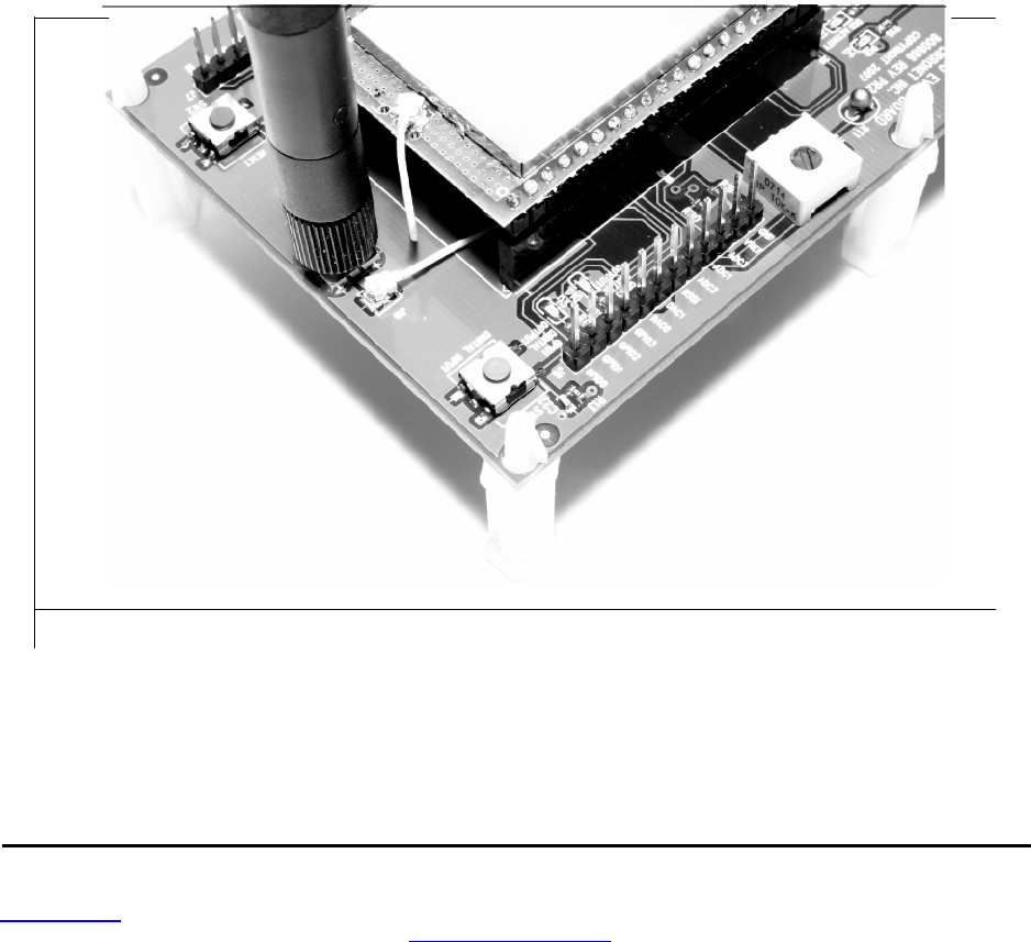
www.RFM.com
Technical support +1.800.704.6079 Page 42 of 58
©2008 by RF Monolithics, Inc. E-mail:
tech sup@rfm.com
DNT900 - 11/05/08
5.3 Developer’s Kit Default Operating Configuration
The default operating configuration of the DNT900DK developer’s kit is TDMA Mode 2, point-to-point, with
transparent serial data at 115.2 kb/s, 8N 1. One DNT900P is preconfigured as a base station and the
other as a remote. The defaults can be overridden to test other operating configurations using the DNT
Wizard utility discussed in Section 5.5. The default RF power setting is 0 dBm (1 mW), which is suitable
for side-by-side operation. The RF power level should be set higher as needed for longer range opera-
tion. Note that setting the RF power to a high level when doing side-by-side testing will overload the
DNT900P receiver and cause erratic operation.
5.4 Development Kit Hardware Assembly
Observe ESD precautions when handling the kit circuit boards. Referring to Figure 5.4.1, confirm each
DNT900P is correctly plugged into an interface board, with the radio oriented so that its U.FL connector is
next to the U.FL connector on the interface board. Check each radio’s alignment in the socket on the
interface board. No pins should be hanging out over the ends of the connector. Next, install the U.FL
jumper cables between the U.FL connectors on the radios and the interface boards. Then install the
dipole antennas. As shown in Figure 5.4.2, confirm there is a jumper on pins J14. The interface boards
can now be powered by the 9 V wall plug transformer power supplies (the interface boards can also be
run for a short time from the 9 V batteries for range testing, etc.).
Figure 5.4.1
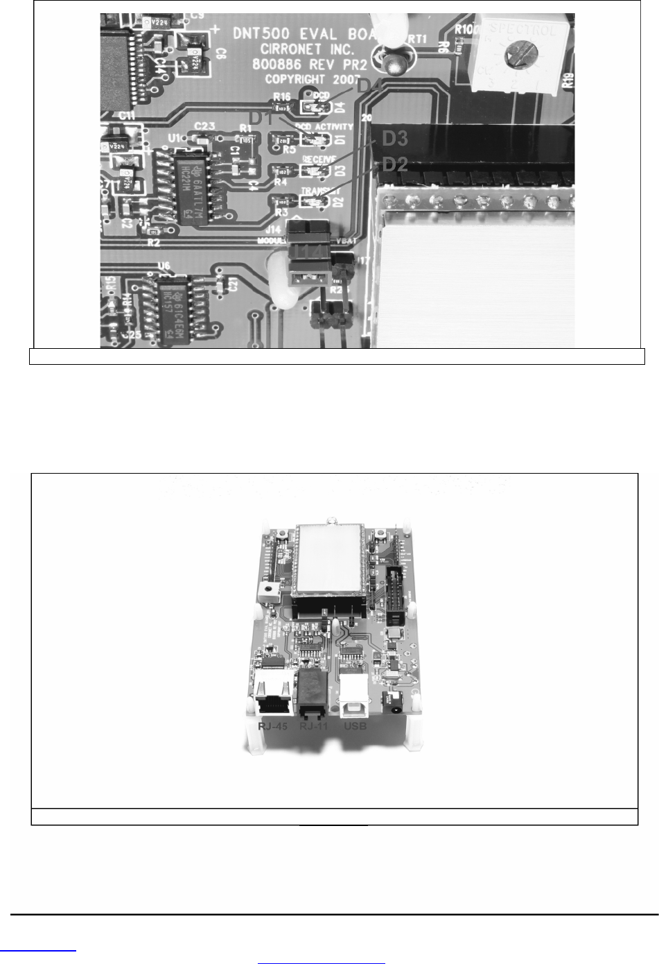
www.RFM.com
Technical support +1.800.704.6079 Page 43 of 58
©2008 by RF Monolithics, Inc. E-mail:
tech sup@rfm.com
DNT900 - 11/05/08
Figure 5.4.2
There are three serial connectors on the interface boards, as shown in Figure 5.4.3. The RJ-45 connector
provides a high-speed RS232 interface to the DNT900P’s main serial port. The USB connector provides
an optional interface to the radio’s main serial port. The RJ-1 1 connector provides a high-speed RS232
interface to the radio’s diagnostic port. The DNT Wizard utility program runs on the radio’s main port.
Figure 5.4.3
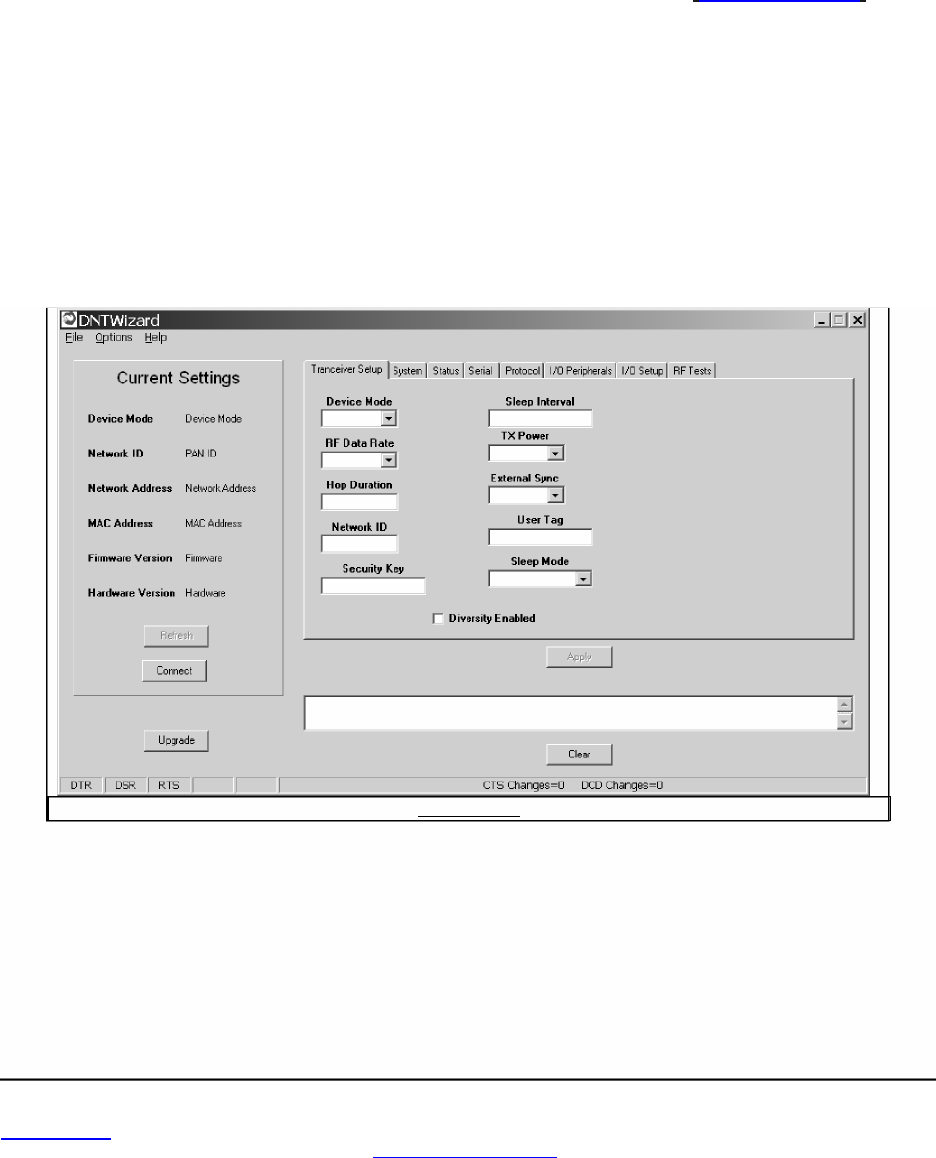
www.RFM.com
Technical support +1.800.704.6079 Page 44 of 58
©2008 by RF Monolithics, Inc. E-mail:
tech sup@rfm.com
DNT900 - 11/05/08
The preferred PC interface is a serial port card capable of operating up to 460.8 kb/s. Many desktop PCs
have a built-in serial port capable of operation at 115.2 kb/s. The kit can be run satisfactorily at the
115.2 kb/s data rate, but not at its fastest throughput. Use the RJ-45 to DB-9F cable assemblies for serial
port operation.
Optionally, the kit can be run from the USB port. Plugging in the USB cable automatically switches opera-
tion from the RJ-45 connector. The USB interface is based on an FT232RL serial-to-USB converter IC
manufactured by FTDI. The driver files for the FT232RL are located in the
USB Driver
folder on the kit
CD, and the latest version of the driver can downloaded from the FTDI website,
www.ftdichip.com.
The
driver creates a virtual COM port on the PC. Power up an interface board with an installed DNT900P
using one of the supplied wall plug power supplies. Next connect the interface board to the PC with a
USB cable. The PC will find the new USB hardware and open up a driver installation dialog box. Click on
the
Browse
button in the dialog box and point to the folder with the FT232R driver files. The driver instal-
lation dialog will run
twice
to complete the FT232R driver installation.
5.5 DNT Wizard Utility Program
The DNT Wizard utility program is located in the
PC Programs
folder on the kit CD. The Wizard requires
no installation and can simply be copied to the PC and run. The Wizard start-up window is shown in
Figure 5.5.1.
Figure 5.5.
1
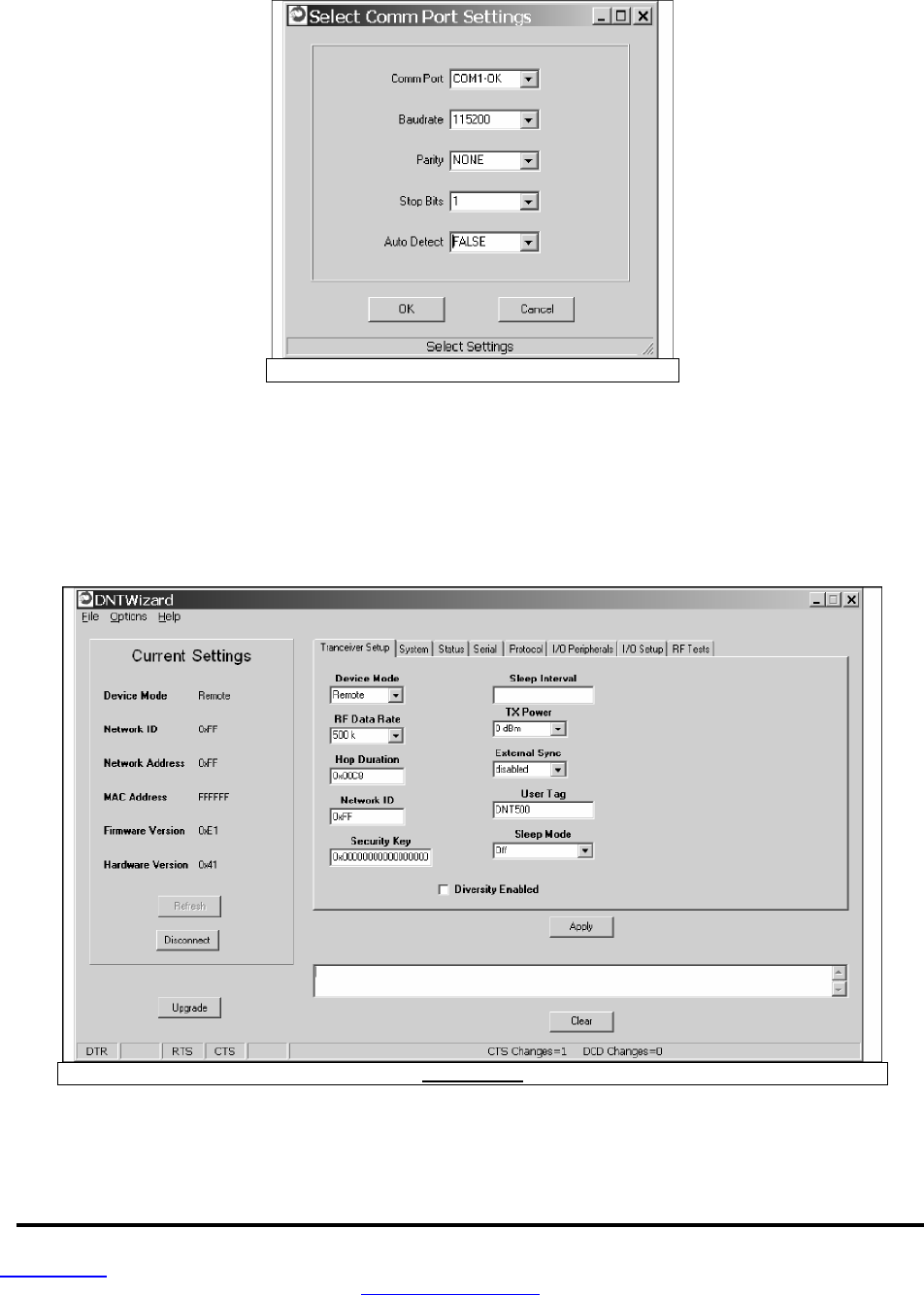
www.RFM.com
Technical support +1.800.704.6079 Page 45 of 58
©2008 by RF Monolithics, Inc. E-mail:
tech sup@rfm.com
DNT900 - 11/05/08
Press the Connect button to open the serial port dialog box, as shown in Figure 5.5.2. Set the data rate to
115.2 kb/s (DNT900 default), select the COM port for the DNT900 interface board and press OK.
Figure 5.5.2
At this point the Wizard will collect configuration parameters from the DNT900. This data is organized
under the first seven tabs, each corresponding to a Bank of register parameters as discussed in Section
4.2. The Transceiver Setup Tab is shown in Figure 5.5.3, and corresponds to Bank 0. The current values
of each Bank 0 parameter are displayed and can be updated by selecting from the drop down menus or
entering data from the keyboard, and then pressing the Apply button. Note that data is displayed and
entered into the Wizard in Big-Endian order. The Wizard automatically reorders multi-byte data to and
from Little-Endian order when building or interpreting messages.
Figure 5.5.3
In addition to conventional mouse and keyboard inputs, the Wizard supports two special function keys, F1
and F2. F1 toggles the serial port DTR line off and on. Pressing F1 the first time after the Wizard is
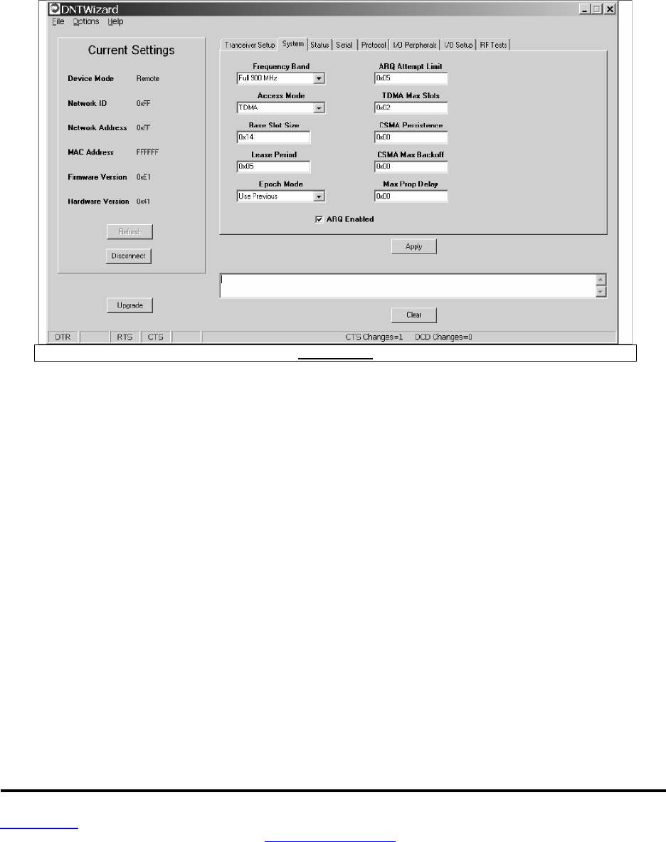
www.RFM.com
Technical support +1.800.704.6079 Page 46 of 58
©2008 by RF Monolithics, Inc. E-mail:
tech sup@rfm.com
DNT900 - 11/05/08
started will place the DNT900 in power down mode. Pressing the F1 key again will reboot and restart the
DNT900. The current status of the DTR line is seen in the lower left corner of the Wizard window. F2
toggles the RTS line. Pressing F2 the first time after the Wizard is started will halt the flow of data from
the DNT900. Pressing the F2 key again will re-enable data flow. The current status of the RTS line is also
seen in the lower left corner of the Wizard window.
Figure 5.5.4 shows the DNT Wizard System tab contents, corresponding to parameter Bank 1. The
default parameters under this tab have been modified to change from CDMA to TDMA operation.
Figure 5.5.4
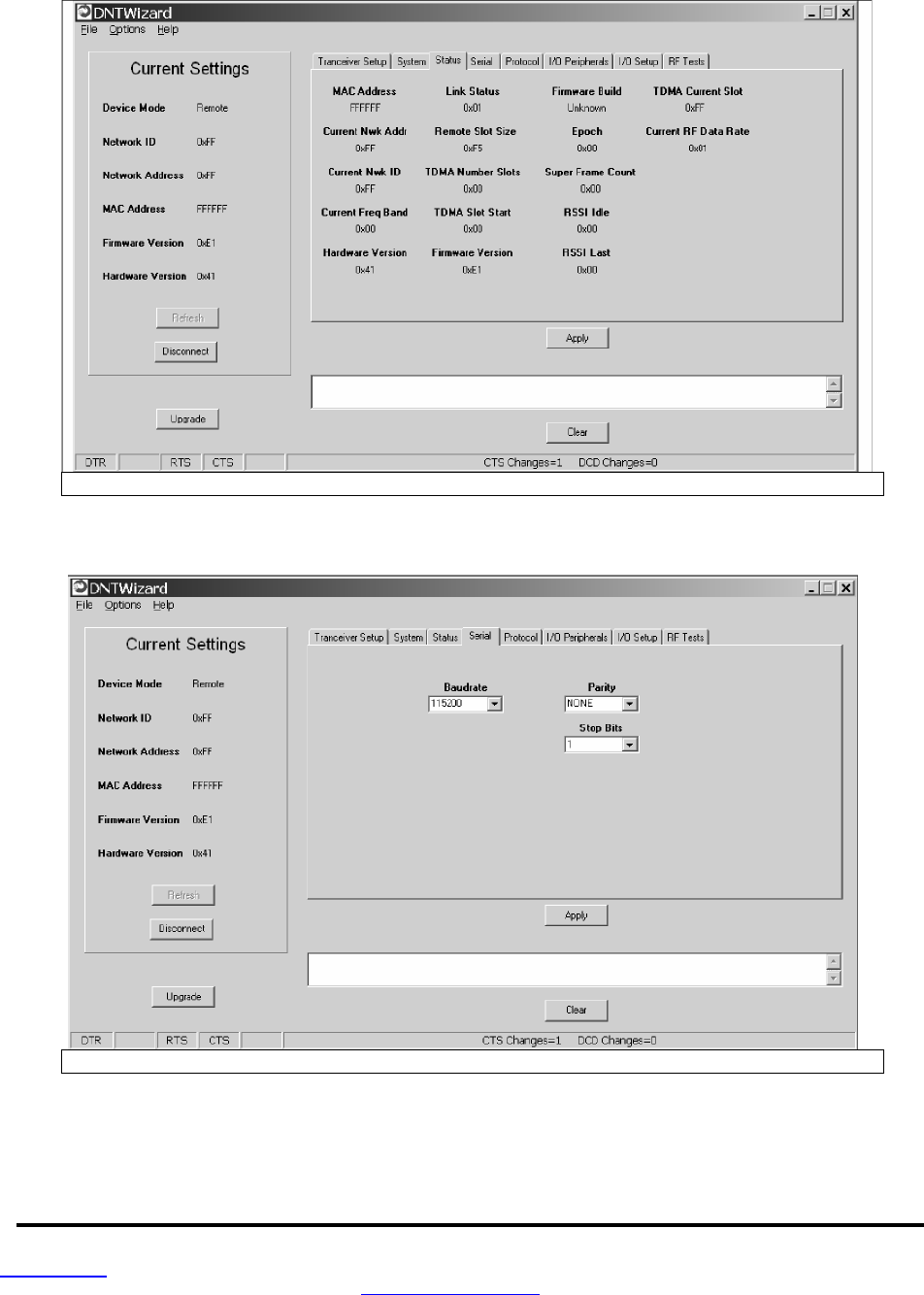
www.RFM.com
Technical support +1.800.704.6079 Page 47 of 58
©2008 by RF Monolithics, Inc. E-mail:
tech sup@rfm.com
DNT900 - 11/05/08
Figure 5.5.5 shows the DNT Wizard Status tab contents, corresponding to parameter Bank 2. Note the
Status tab contains read-only parameters.
Figure 5.5.5
Figure 5.5.6 shows the DNT Wizard Serial tab contents corresponding to parameter Bank 3. The values
shown below are the defaults for serial port operation.
Figure 5.5.6
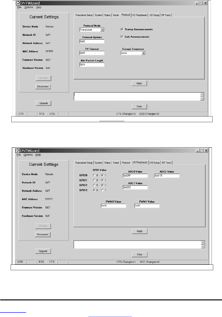
www.RFM.com
Technical support +1.800.704.6079 Page 48 of 58
©2008 by RF Monolithics, Inc. E-mail:
tech sup@rfm.com
DNT900 - 11/05/08
Figure 5.5.7 shows the DNT Wizard Protocol tab contents, corresponding to parameter Bank 4. Trans-
parent data serial communication is currently chosen.
Figure 5.5.7
Figure 5.5.8 shows the DNT Wizard I/O Peripherals tab contents, corresponding to parameter Bank 5.
GPIO ports 0 - 2 are logic high, GPIO port 3 is logic low. The 10-bit ADC inputs and PWM outputs are
given in Big-Endian byte order.
Figure 5.5.8
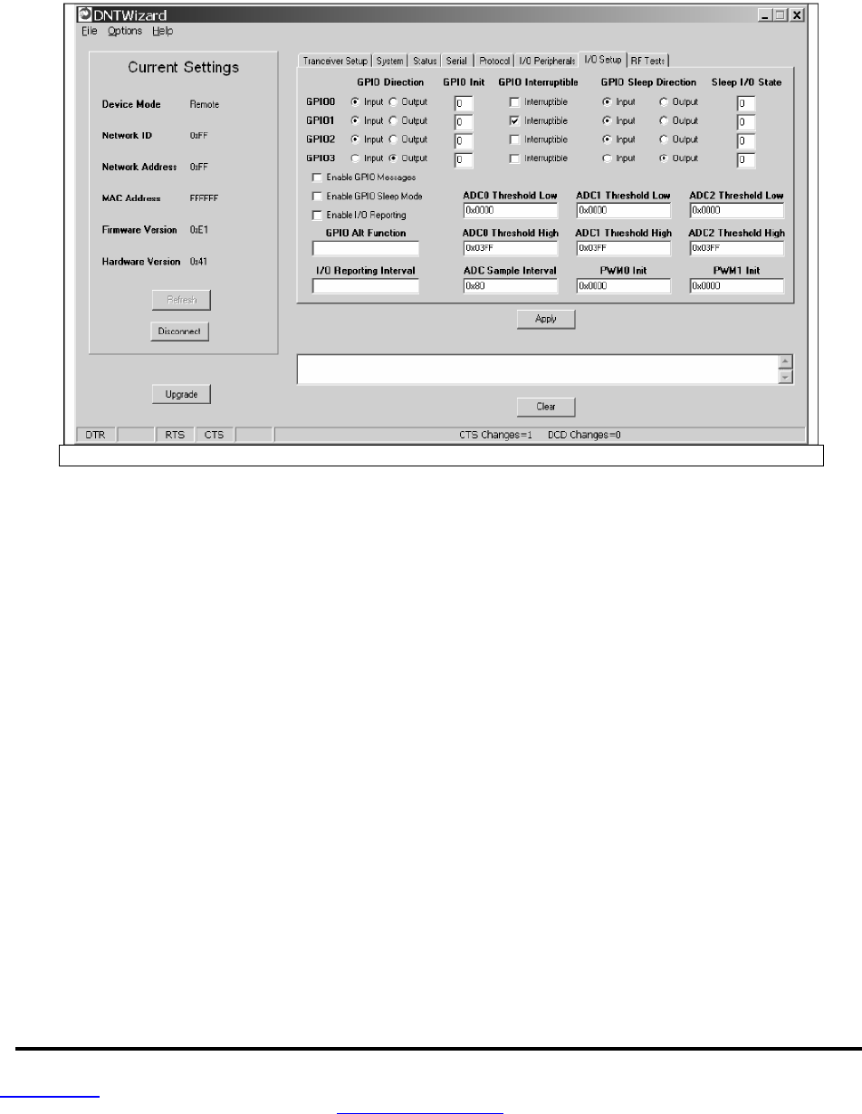
www.RFM.com
Technical support +1.800.704.6079 Page 49 of 58
©2008 by RF Monolithics, Inc. E-mail:
tech sup@rfm.com
DNT900 - 11/05/08
Figure 5.5.9 shows the DNT Wizard I/O Setup tab contents, corresponding to parameter Bank 6. This tab
allows the direction of the GPIO ports to be set both for active and sleep mode. The power-up initial
values of the GPIO outputs can also be specified, and whether an input can generate a wake-up interrupt.
GPIO event messaging and/or periodic reporting and reporting interval can also be specified under this
tab. The ADC sampling interval and the high and low thresholds for event reporting on each ADC channel
can be set, along with the start-up output values for each PWM (DAC) channel.
Figure 5.5.9
Figure 5.5.10 shows the DNT Wizard RF Tests tab contents. A message placed in the Transmit Window
is sent to the specified MAC address each time the Apply button is pressed. Messages received are
displayed in the lower text box. The receive message text box can be cleared with the Clear button. Note
that a base station will accept a message from a remote with the MAC address 0x000000 regardless of
the base station’s actual MAC address.
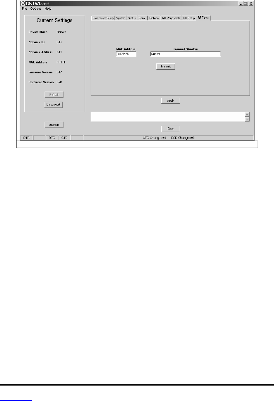
www.RFM.com
Technical support +1.800.704.6079 Page 50 of 58
©2008 by RF Monolithics, Inc. E-mail:
tech sup@rfm.com
DNT900 - 11/05/08
Figure 5.5.10
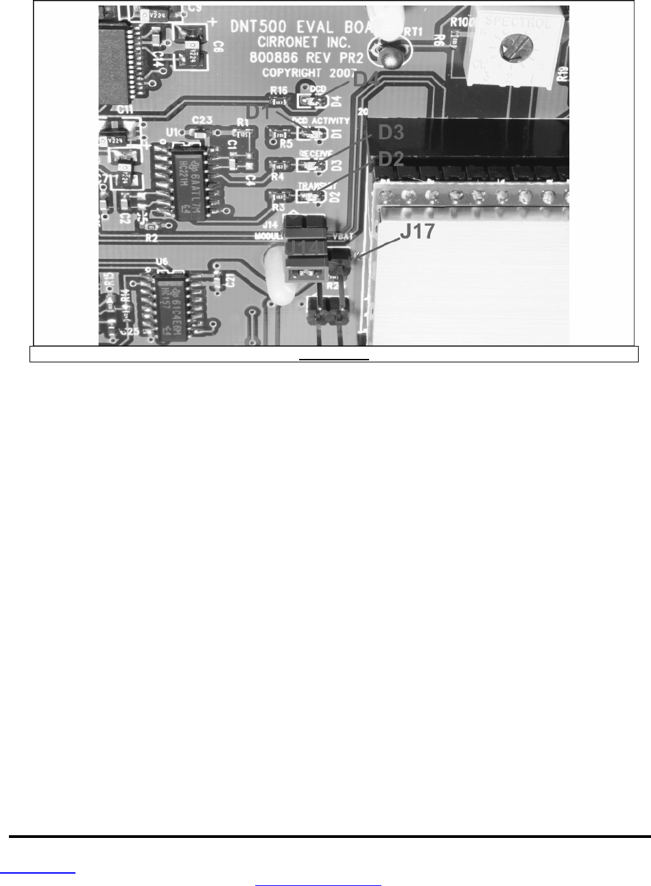
www.RFM.com
Technical support +1.800.704.6079 Page 51 of 58
©2008 by RF Monolithics, Inc. E-mail:
tech sup@rfm.com
DNT900 - 11/05/08
5.6 DNT900 Interface Board Features
The location of LEDs D1 through D4 and jumper pin sets J14 and J17 are shown in
Figure 5.6.1.
Figure 5.6.1
Amber DCD LED D4 illuminates on a remote to indicate it is registered with the base station and can
participate in RF communications. LED D4 illuminates on the base station when one or more remotes are
registered to it. Green Activity LED D1 illuminates on a remote when transmitting data, and illuminates
on a base when receiving data. Red Receive LED D3 illuminates when sending received data through
the serial port to the PC. Green Transmit LED D2 illuminates when the PC sends data through the serial
port to be transmitted.
Jumper pin set J14 is provided to allow measurement of the DNT900P current. For normal operation J14
has a shorting plug installed. Jumper pin set J17 allows the DNT900P CFG pin to be grounded by install-
ing a shorting plug. This places the DNT900P in protocol mode.
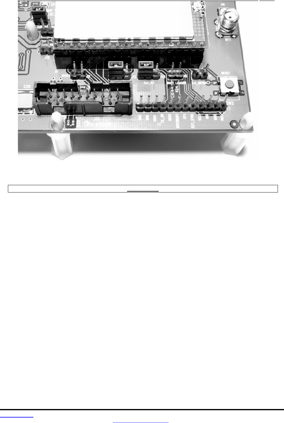
www
.RFM.com
Technical support +1.800.704.6079 Page 52 of 58
©2008 by RF Monolithics, Inc. E-mail:
tech sup@rfm.com
DNT900 - 11/05/08
Figure 5.6.2
Figure 5.6.2 shows the connectors to the right of the DNT900P mounting socket. Jumper pin set J9 allow
the DNT900P reset line to be routed to JTAG interface connector J10. J18 allows the DNT900P reset line
to be grounded. Note that the JTAG operation is usually limited to factory testing. For normal operation
pin sets J9 and J18 should not have a shorting block installed. Jumper pin sets J12 and J13 normally
have shorting plugs installed as shown in Figure 5.6.2, which connects the DNT900P UART0_TXD and
UART0_RXD pins to the respective serial data lines on the evaluation board. It is possible to connect
directly to UART0_TXD and UART0_RXD by moving the jumpers over. In this case, J1 1-1 is the input for
transmitted data and J1 1-2 is the output for received data. Note this a 3 V logic interface. Placing a short-
ing plug on jumper pin set J6 allows the DNT900P to be powered up in boot loader mode. This is used for
factory code loads and functional testing. The DNT900 has its own boot loader utility that allows the
protocol firmware to be installed with a terminal program that supports YMODEM. Pin strip J7 provides
access to various DNT900 pins as shown on the silkscreen. Pressing switch SW2 will reset the
DNT900P.
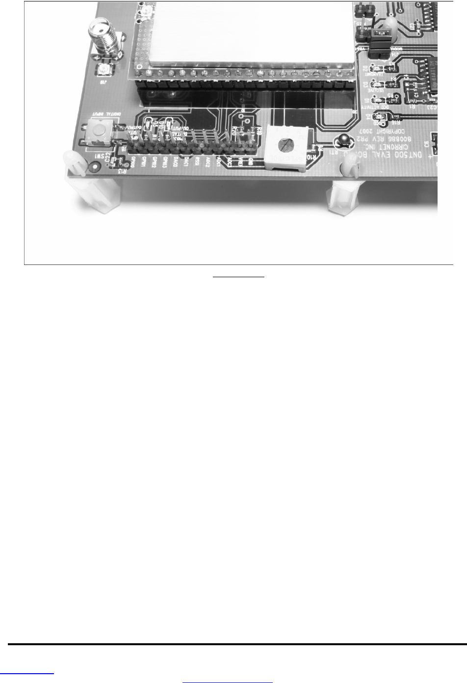
www.RFM.com
Technical support +1.800.704.6079 Page 53 of 58
©2008 by RF Monolithics, Inc. E-mail:
tech sup@rfm.com
DNT900 - 11/05/08
Figure 5.6.3
Figure 5.6.3 shows the connectors to the left of the DNT900P mounting socket. Pressing switch SW2
switches GPIO0 from logic high to logic low. Pin strip J8 provides access to various DNT900 pins as
shown on the silkscreen. The wiper of pot R10 drives the input of ADC1. Clockwise rotation of the pot
wiper increases the voltage. Thermistor RT1 is part of a voltage divider that drives ADC0. LED D5 illumi-
nates when GPIO1 is set as a logic high output. LED D10 illuminates when GPIO3 is set as a logic high.
The DNT900P interface board includes a 5 V regulator to regulate the input from the 9 V wall transformer
power supply. Note: do not attempt to use the 9 V wall transformer power supply to power the DNT900P
directly. The maximum allowed voltage input to the DNT900P is 5.5 V.

www.RFM.com
Technical support +1.800.704.6079 Page 54 of 58
©2008 by RF Monolithics, Inc. E-mail:
tech sup@rfm.com
DNT900 - 11/05/08
6.0 Demonstration Procedure
The procedure below provides a quick demonstration of the DNT900 using a DNT900DK development kit:
1. Confirm that each DNT900P is installed correctly in an interface board, and that the U.FL jumpers
between the DNT900P radios and the interface boards are installed. Also confirm that a dipole
antenna is installed on each interface board, and that J14 has a jumper block installed on each
interface board. See Figures 5.4.1, 5.4.2 and 5.4.3 above.
2. Attach each transceiver/interface board to a computer with the DNT Wizard program installed.
3. Place the transceivers at least 3 feet (one meter) apart.
4. Start the DNT Wizard program on both computers.
5. On each computer, press the Connect button on the Wizard window. This will open a serial port
setup dialog box. Set the baud rate to 115.2 kb/s and select the COM port the DNT900 is con-
nected to. Parameter values on the left of the Wizard main window and on the Transceiver Setup
tab will fill in.
6. Select the RF Test tab on the Wizard. A message placed in the Transmit Window is sent to the
specified MAC address each time the Apply button is pressed. Messages received are displayed
in the lower text box. The receive message text box can be cleared with the Clear button.

www.RFM.com
Technical support +1.800.704.6079 Page 55 of 58
©2008 by RF Monolithics, Inc. E-mail:
tech sup@rfm.com
DNT900 - 11/05/08
7.0 Troubleshooting
DNT900 not responding - make sure DTR is asserted (logic low) to bring the radio out of sleep mode.
Can not enter protocol mode - make sure the host data rate is correct. The DNT900 defaults to 115.2
kb/s. If using the escape sequence command, make sure a pause of at least 20 ms precedes the escape
sequence.
A remote never detects carrier (DCD) - check that the base station is running, and that the remote Ini-
tialNwkID parameter is the same as the base station, or is set to 0xFF. Also check that remote is receiv-
ing an adequate signal from the base station.
Carrier is detected, but no data appears to be received - make sure that RTS is asserted to enable re-
ceive character flow. Make sure the RF transmit power is not on a high settings if the nodes are close
together.
The DNT900 is interfering with other nearby circuits - It is possible for the RF energy from the DNT900 to
be rectified by nearby circuits that are not shielded for RF, manifesting as a lower frequency pulse noise
signal. If possible, place the antenna at least 1 foot away from the transceiver module, and 3 feet from
other system circuit boards. Place sensitive circuits in a grounded metal casing to keep out RFI.
Range is extremely limited - this is usually a sign of a poor antenna connection or the wrong antenna.
Check that the antenna is firmly connected. If possible, remove any obstructions in the near field of the
antenna (nominal 3 ft radius).
Transmitting terminal flashes (drops) CTS occasionally - this indicates that the transmitter is unable to
reliably get its data across. This may be the result of an interfering signal, but most often is caused by
overloading of the network. Adjusting the protocol parameters may increase the network efficiency.
Receiving terminal drops characters periodically - set the number of retries to a high number and send a
few characters. Check that the transmitted data can get through under these conditions. Sometimes this
symptom is caused by an application that is explicitly dependent on the timing of the received data
stream. The nature of an RF channel imposes a degree of uncertainty in end-to-end transmission delay.

www.RFM.com
Technical support +1.800.704.6079 Page 56 of 58
©2008 by RF Monolithics, Inc. E-mail:
tech sup@rfm.com
DNT900 - 11/05/08
8.0 Appendices
8.1 Ordering Information
DNT900C: transceiver module for solder pad mounting
DNT900P: transceiver module for pin-socket mounting
8.2 Technical Support
For DNT900 technical support call RFM at (678) 684-2000 between the hours of 8:30 AM and 5:30 PM
Eastern Time.
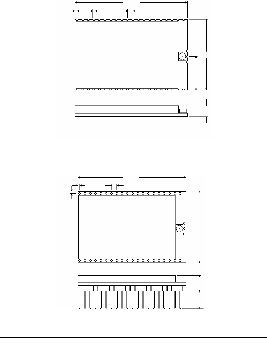
www.RFM.com
Technical support +1.800.704.6079 Page 57 of 58
©2008 by RF Monolithics, Inc. E-mail:
tech sup@rfm.com
DNT900 Integration Guide - 10/20/08
8.3 DNT900 Mechanical Specifications
DNT900C Outline and Mounting Dimensions
DNT900P Outline and Mounting Dimensions
Dimensions in inches
Figure 8.3.2
2.010
0.040
0.040
0.100
1
__
1.260
0.595
40
0.180
Dimensions in inches
Figure 8.3.1
2.050
0.040
0.100
1.360
1
40
0.050
0.285
0.333
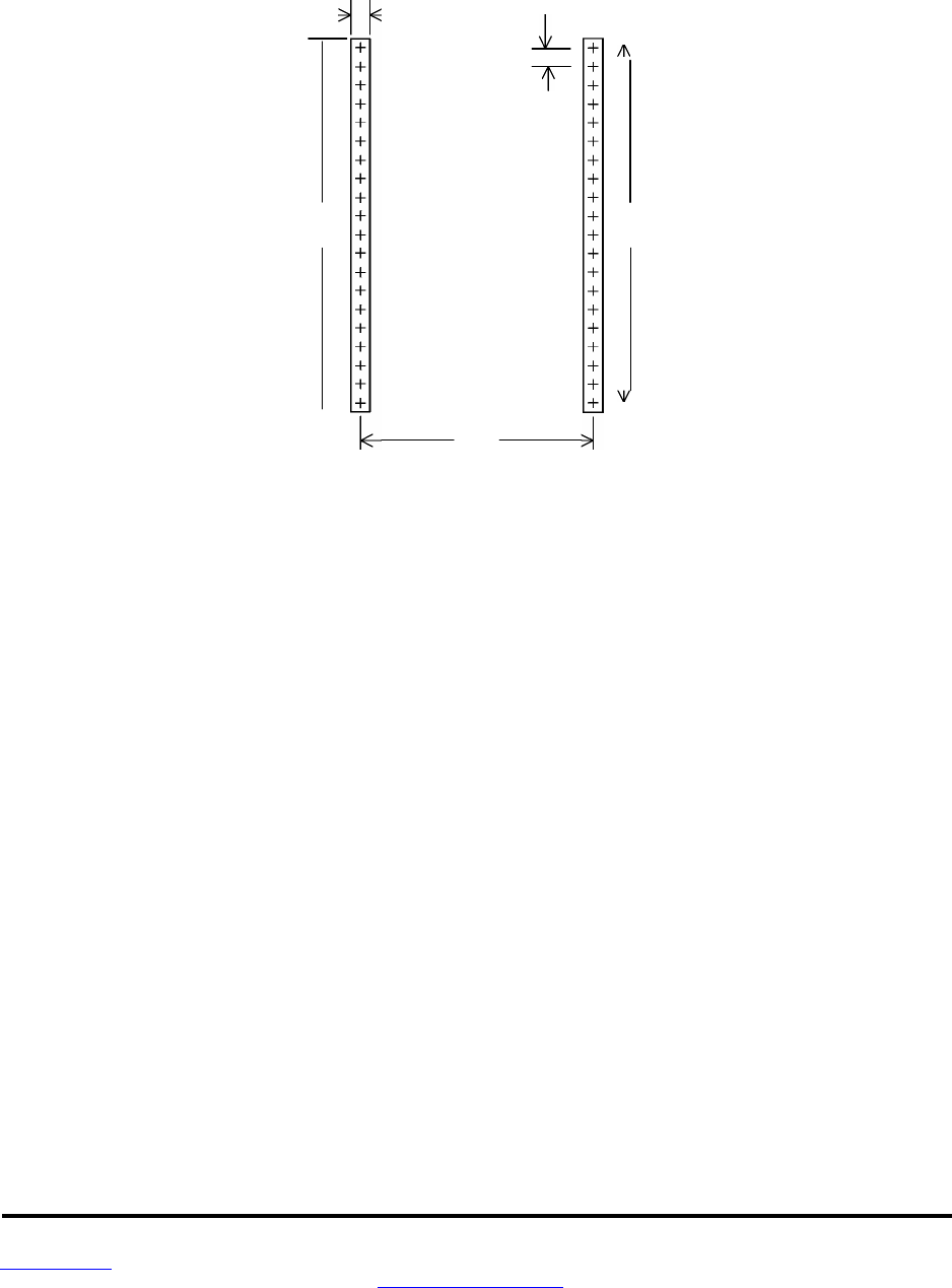
www.RFM.
com
Technical support +1.800.704.6079 Page 58 of 58
©2008 by RF Monolithics, Inc. E-mail:
tech sup@rfm.com
DNT900 Integration Guide - 10/20/08
DNT900P Interface Connector
PCB Layout Detail
Connectors are FCI Electronics 75915-420LF or equivalent
Dimensions in inches and (mm)
Figure 8.3.3
0.1
(2.5)
0.1
(2.5)
Minimum plated PCB
hole diameter 0.03 (0.75)
1.26
1.9
(48.3)
2 . 0
(50.8)

www.RFM.com
Technical support +1.800.704.6079 Page 59 of 58
©2008 by RF Monolithics, Inc. E-mail:
tech sup@rfm.com
DNT900 Integration Guide - 10/20/08
9.0 Warranty
Seller warrants solely to Buyer that the goods delivered hereunder shall be free from defects in materials
and workmanship, when given normal, proper and intended usage, for twelve (12) months from the date
of delivery to Buyer. Seller agrees to repair or replace at its option and without cost to Buyer all defective
goods sold hereunder, provided that Buyer has given Seller written notice of such warranty claim within
such warranty period. All goods returned to Seller for repair or replacement must be sent freight prepaid
to Seller’s plant, provided that Buyer first obtain from Seller a Return Goods Authorization before any
such return. Seller shall have no obligation to make repairs or replacements which are required by normal
wear and tear, or which result, in whole or in part, from catastrophe, fault or negligence of Buyer, or from
improper or unauthorized use of the goods, or use of the goods in a manner for which they are not de-
signed, or by causes external to the goods such as, but not limited to, power failure. No suit or action
shall be brought against Seller more than twelve (12) months after the related cause of action has oc-
curred. Buyer has not relied and shall not rely on any oral representation regarding the goods sold here-
under, and any oral representation shall not bind Seller and shall not be a part of any warranty.
THE PROVISIONS OF THE FOREGOING WARRANTY ARE IN LIEU OF ANY OTHER WARRANTY,
WHETHER EXPRESS OR IMPLIED, WRITTEN OR ORAL (INCLUDING ANY WARRANTY OR
MERCHANT ABILITY OR FITNESS FOR A PARTICULAR PURPOSE). SELLER’S LIABILITY ARISING
OUT OF THE MANUFACTURE, SALE OR SUPPLYING OF THE GOODS OR THEIR USE OR
DISPOSITION, WHETHER BASED UPON WARRANTY, CONTRACT, TORT OR OTHERWISE, SHALL
NOT EXCEED THE ACTUAL PURCHASE PRICE PAID BY BUYER FOR THE GOODS. IN NO EVENT
SHALL SELLER BE LIABLE TO BUYER OR ANY OTHER PERSON OR ENTITY FOR SPECIAL,
INCIDENTAL OR CONSEQUENTIAL DAMAGES, INCLUDING, BUT NOT LIMITED TO, LOSS OF
PROFITS, LOSS OF DATA OR LOSS OF USE DAMAGES ARISING OUT OF THE MANUFACTURE,
SALE OR SUPPLYING OF THE GOODS. THE FOREGOING WARRANTY EXTENDS TO BUYER
ONLY AND SHALL NOT BE APPLICABLE TO ANY OTHER PERSON OR ENTITY INCLUDING,
WITHOUT LIMITATION, CUSTOMERS OF BUYERS.