Muratec Automation VEHICLECMC CMC User Manual
Muratec Automation Co.,LTD CMC Users Manual
Users Manual

Muratec Automation Co., Ltd.
Muratec Automation Co., Ltd.Muratec Automation Co., Ltd.
Muratec Automation Co., Ltd.
Communication unit CMC
Operation Manual
※Operation Manual for Communication unit CMC
Model: CMC(CMC-BC,CMC-BM,CMC-TR)
1
st
edition January 31, 2010
Control Design Section,
Semiconductor Engineering Dept.
MURATEC AUTOMATION CO., LTD.
Rev. Approved
Checked
Prepared
Rev.
Rev.
Rev.1 2011/03/03
Change FCC ID
Engineerring Dept
2011.2.10
Kawashima
Kawashima
Development Dept
2011.2.1
Onishi
Onishi
Development Dept.
2011.01.31
M.KURODA
Kuroda
Doc. No.
YSDA-3495△1

Muratec Automation Co., Ltd.
Muratec Automation Co., Ltd.Muratec Automation Co., Ltd.
Muratec Automation Co., Ltd.
< Revision History >
Ver.
Date Page Description
0 2011/01/31 The first edition.
1 2011/03/03 3,8,16
Change FCC ID
1

Muratec Automation Co., Ltd.
Muratec Automation Co., Ltd.Muratec Automation Co., Ltd.
Muratec Automation Co., Ltd.
2
〈
〈〈
〈Contents〉
〉〉
〉
1. Introduction................................................................................................................................ 3
1.1. Construction of the documents .......................................................................................... 3
1.2. Application.......................................................................................................................... 3
1.3. Related Rules, Laws .......................................................................................................... 3
1.4. Abbreviations...................................................................................................................... 3
2. Safety......................................................................................................................................... 4
2.1. Alert Boxes ......................................................................................................................... 4
3. Outline of Communication Unit CMC ........................................................................................ 8
3.1. Overview............................................................................................................................. 8
3.2. CMC configuration.............................................................................................................. 8
3.3. Function of each unit........................................................................................................ 11
3.4. The Block Diagram of CMC ............................................................................................. 12
3.5. Outline form of CMC......................................................................................................... 13
3.6. FCC standard ................................................................................................................... 16
4. CMC-BC Board Setting ........................................................................................................... 17
4.1. CMC-BC Board Check ..................................................................................................... 17
4.2. NBV-BC Printed Circuit Board DIP Switch Settings ........................................................ 18
5. CMC-BM Board Setting........................................................................................................... 22
5.1. CMC-BM Board Check..................................................................................................... 22
6. Communications Adjustment................................................................................................... 24
6.1. Prerequisites .................................................................................................................... 24
6.2. Check before Vehicle Start-Up (Track Power Panel is OFF) .......................................... 24
6.3. Check before Vehicle Start-Up (Track Power Panel is ON) ............................................ 25
6.4. Check and Adjustments of each Level of CMC-BM ........................................................ 26
7. Specification ............................................................................................................................ 32
7.1. CMC-BC (Communication Modem Controller :Base Controller).................................. 32
7.2. CMC-BM(Communication Modem Controller :Base Modem) ...................................... 32
7.3. CMC-TR(Communication Modem Controller :TRansformer)....................................... 33
8. Error process ........................................................................................................................... 34

Muratec Automation Co., Ltd.
Muratec Automation Co., Ltd.Muratec Automation Co., Ltd.
Muratec Automation Co., Ltd.
3
1. Introduction
1.1. Construction of the documents
The documents of the communication units CMC are as follows.
Kind of document Name of the document # of documents
Operation manual Communication unit CMC Operation Manual YSDA-3495
Installation manual Communication unit CMC Installation Manual YSDA-3496
Block Diagrams Communication unit CMC Block Diagrams YSDA-3493
1.2. Application
This document describes the operation of communication unit for transport system, OHT, OHS,
etc.
1.3. Related Rules, Laws
(1) FCC Part15 Subpart C: 2010
FCC ID : ZBQVEHICLECMC
(2) FCC Part15 Subpart B: 2010 Class A
1.4. Abbreviations
(1) CMC : Communication Modem Controller
(2) CMC-BM : Communication Modem Controller :Base Modem
(3) CMC-BC : Communication Modem Controller :Base Controller
(4) CMC-TR : Communication Modem Controller :TRansformer
(5) COM : COmmunication Modem
Muratec Automation Co., Ltd.
Muratec Automation Co., Ltd.Muratec Automation Co., Ltd.
Muratec Automation Co., Ltd.
4
2. Safety
2.1. Alert Boxes
2.1.1. General
(1) Read and understand fully this manual and attached documents before operating the
products.
(2) Engage specialists in electrical and mechanical works.
(3) Don’t improve the product by yourselves.
(4) Be sufficiently proficient with the equipment, the relevant safety knowledge and the
precautions prior to using this product.
In the content of this “Safety Precautions ”, items which need to be alert shall be classified
into “DANGER”, “WARNING” and ”CAUTION”.
2.1.2.
Definitions of DANGER, WARNING and CAUTION
DANGER: An imminently hazardous situation which, if not avoided, will result in
death or serious injury.
WARNING: A potentially hazardous situation which, if not avoided, could result
in death or serious injury.
CAUTION: A potentially hazardous situation which, if not avoided, may result in
minor or moderate injury.
[Note 1]
Medium degree of injuries or light injuries refers to injuries, e.g., burns and electric shock,
which do not require hospitalization of or prolonged hospital visit by the victims. As material
losses refers to expanded losses pertaining to the damage of property and equipment.
[Note 2]
Depending on the situation, the events described under “WARNING” may also result in
severe outcome. In either case, make sure that the advice is followed.
After reading, make sure this information shall be kept at places where it can always be
read by users.
Muratec Automation Co., Ltd.
Muratec Automation Co., Ltd.Muratec Automation Co., Ltd.
Muratec Automation Co., Ltd.
5
2.1.3. Precautions on use
DANGER
Follow the following advice strictly to avoid electric shock or burns.
1. Don’t enter the operation area of the vehicle. Work on the ladder may collide to
the vehicle and may cause injury.
2. Don’t touch the vehicle on the track when Power Supply Panel output the
power.
3. Don’t touch the moving parts of the vehicle while it is in operation. Doing so
may cause injuries.
4. Only those who received training for maintenance and teaching can do
maintenance and teaching.
5. Make sure the earth terminals for the relate equipment shall be grounded. Not
doing so may cause electric shock.
6. Don’t break the cable, impose excessive stress, place heavy weights, or pinch it
between items. Doing so may cause electric shock.
WARNING
1. Don’t use the equipment at locations where water, corrosive atmosphere, or
flammable gas is present, or beside flammable items. Doing so may cause life
and fails.
Muratec Automation Co., Ltd.
Muratec Automation Co., Ltd.Muratec Automation Co., Ltd.
Muratec Automation Co., Ltd.
6
2.1.4. Storage
PROHIBITION
1. Don’t store the equipment at locations where it is subject to rain, ater hazardous
gas or liquid.
MANDATORY ACTION
1. Store the equipment at locations in not subjected to sunshine. Store it at
predetermined relative humidity and temperature. 0 degrees C. - 50 degrees
C., 90% RH and below, no dew.
2.1.5. Installation
WARNING
1. Don’t climb on top of the equipment or place heavy items on it.
Doing so may cause injuries.
2. Don’t block the air inlet and outlet ports or allow foreign particles to
enter them. Doing so may cause fire.
3. Follow the installation direction strictly as it is so design for
dissipation of heat, fails or fire.
4. Don’t hit the equipment with strong impact. Doing so may cause
equipment fails.
Muratec Automation Co., Ltd.
Muratec Automation Co., Ltd.Muratec Automation Co., Ltd.
Muratec Automation Co., Ltd.
7
2.1.6. Maintenance and Inspection
PROHIBITION
1. Don’t engage non-specialist technicians to disassemble and repair
the equipment.
DANGER
1. Before servicing CMC-BC,CMC-BM,CMC-TR,always shut off the
power supply.
If the communication signals are overlaid onto the non-conductive
power line, also shut off the power source of the non-conductive
power line before starting maintenance on CMC-BM and CMC-TR.
Not doing so may cause electric shock.

Muratec Automation Co., Ltd.
Muratec Automation Co., Ltd.Muratec Automation Co., Ltd.
Muratec Automation Co., Ltd.
8
3. Outline of Communication Unit CMC
3.1. Overview
The communication unit CMC (Communication Modem Controller) is used for the communication
between the ground Vehicle Controller and several vehicles in the conveyance system made by
MURATEC AUTOMATION CO., LTD.
The communication signals are overlaid onto the power line for non-conductive power supply to
the vehicles. In some systems, a separate signal lines may be used.
CMC meet the requirements of FCC Part15 Subpart C. The FCC ID is as follows.
FCC ID of CMC: ZBQVEHICLECMC
It modulates the signals sent from the Vehicle controller and transmits the modulated signals to
the vehicles. It also demodulates the signals sent from the vehicles and transmits them to the
Vehicle controller.
The communication method in use is FSK ( frequency shift keying).
The communication frequencies are as follows.
From to Frequency
(1) CMC → Vehicles: 300.33 kHz
(2) Vehicles → CMC: 353.25 kHz
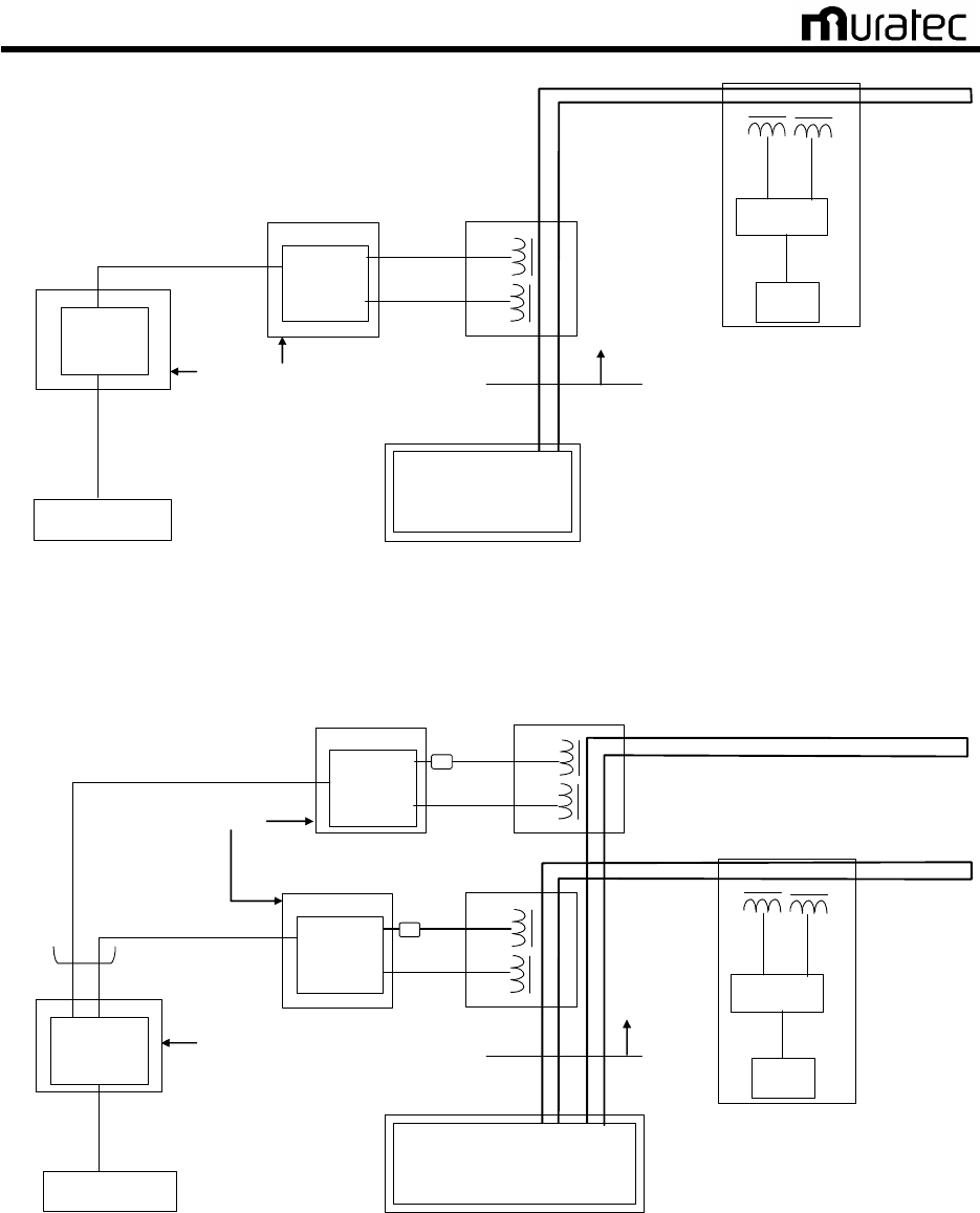
3.2. CMC configuration
Figures 1 to 3 show the basic configuration of CMC.
CMC consists of the following units.
(1)CMC-BC (Communication Modem Controller :Base Controller)
Printed circuit NBV-BC2
DC power supply (5V)
Case
(2)CMC-BM (Communication Modem Controller :Base Modem)
Printed circuit BV-BM3
DC power supply (24V)
Case
(3)CMC-TR(Communication Modem Controller :TRansformer)
Communication transformer(transmission, reception)
Case
Muratec Automation Co., Ltd.
Muratec Automation Co., Ltd.Muratec Automation Co., Ltd.
Muratec Automation Co., Ltd.
9
Vehicle Controller
Power Supply Panel
CMC
CMCCMC
CMC-
--
-BC
BCBC
BC
Power Supply Unit
Power Supply Line
(Parallel Wire)
PCB
NBV-BC2
PCB
BV-BM3
TX
RX
CMC
CMCCMC
CMC-
--
-BM
BMBM
BM
CMC
CMCCMC
CMC-
--
-TR
TRTR
TR
Digital Signal line with shield
Digital Signal line with shield
Analog Signal line
Modem
CPU
TX RX
Vehicle
Track
100V or 200V 50/60Hz
Fig. 1 Basic configuration of CMC
Power Supply Panel
CMC
CMCCMC
CMC-
--
-BC
BCBC
BC
Power Supply Unit
Power Supply Line
(Parallel Wire)
CMC
CMCCMC
CMC-
--
-BM
BMBM
BM
TX
RX
CMC
CMCCMC
CMC-
--
-TR
TRTR
TR
Digital Signal line with shield
Digital Signal line with shield
Analog Signal line
Modem
CPU
TX RX
Vehicle
Track
PCB
BV-BM3
CMC
CMCCMC
CMC-
--
-BM
BMBM
BM
TX
RX
CMC
CMCCMC
CMC
-
--
-
TR
TRTR
TR
Digital Signal line with shield
Analog Signal line
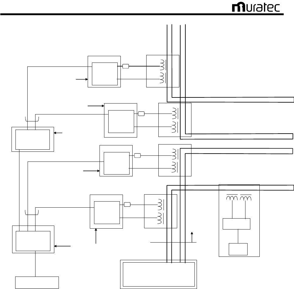
Output: 8-Port maximum
PCB
NBV-BC2
Vehicle Controller
PCB
BV-BM3
Ferrite
Core
Ferrite
Core
100V or 200V 50/60Hz
100V or 200V 50/60Hz
Fig. 2 Modified CMC configuration Example 1
Muratec Automation Co., Ltd.
Muratec Automation Co., Ltd.Muratec Automation Co., Ltd.
Muratec Automation Co., Ltd.
10
Power Supply Panel
Power Supply Unit
Power Supply Line
(Parallel Wire)
Digital Signal line with shield
Digital Signal line with shield
Modem
CPU
TX RX
Vehicle
Track
Digital Signal line with shield
Output: 8-Port maximum
CMC
CMCCMC
CMC-
--
-BC
BCBC
BC
PCB
NBV-BC2
Vehicle Controller
CMC
CMCCMC
CMC-
--
-BM
BMBM
BM
TX
RX
CMC
CMCCMC
CMC-
--
-TR
TRTR
TR
Analog Signal line
PCB
BV-BM3
CMC
CMCCMC
CMC-
--
-BM
BMBM
BM
TX
RX
CMC
CMCCMC
CMC
-
--
-
TR
TRTR
TR
Analog Signal line
PCB
BV-BM3
CMC
CMCCMC
CMC-
--
-BM
BMBM
BM
TX
RX
CMC
CMCCMC
CMC-
--
-TR
TRTR
TR
PCB
BV-BM3
CMC
CMCCMC
CMC-
--
-BM
BMBM
BM
TX
RX
CMC
CMCCMC
CMC
-
--
-
TR
TRTR
TR
PCB
BV-BM3
CMC
CMCCMC
CMC-
--
-BC
BCBC
BC
PCB
NBV-BC2
Output: 8-Port maximum
Digital Signal line with shield
Ferrite
Core
Ferrite
Core
Ferrite
Core
Ferrite
Core
100V or 200V 50/60Hz
100V or 200V 50/60Hz
100V or 200V 50/60Hz
100V or 200V 50/60Hz
100V or 200V 50/60Hz
Fig. 3 Modified CMC configuration Example 2

Muratec Automation Co., Ltd.
Muratec Automation Co., Ltd.Muratec Automation Co., Ltd.
Muratec Automation Co., Ltd.
11
3.3. Function of each unit
3.3.1. CMC-BC
(Communication Modem Controller :Base Controller)
This is an interface unit to handle the signals from/to the vehicle controller. It also serves as the
multiplexer for several CMC-BM units.
CMC-BC can work in two different modes, master mode and slave mode. It allows the user to use
the multiple units according to the scale of the conveyance system.
The CMC-BC unit may vary in its outward form depending on the conveyance system. However,
the internal configuration is common.
Figure 4 shows the block diagram of CMC-BC.
Figure 5 shows the outward form of the CMC-BC’s main printed circuit board NBV-BC.
Figure 6 shows for example the outward form of the CMC-BC unit.
3.3.2. CMC-BM
(Communication Modem Controller :Base Modem)
This is a modem unit to handle the signals from/to several vehicles.
It incorporates a driver that modulates the digital signals sent from CMC-BC to analog signals
and overlay the converted signals onto the non-conductive power line or signal line.
It also demodulates the analog signals sent from the vehicles to digital signals and transmits
them to CMC-BC.
The CMC-BM unit may vary in its outward form depending on the conveyance system. However,
the internal configuration is common.
Figure 4 shows the block diagram of CMC-BM.
Figure 7 shows the outline form of the CMC-BM’s main printed circuit board BV-BM2.
Figure 8 shows for example the outline form of the CMC-BM unit.
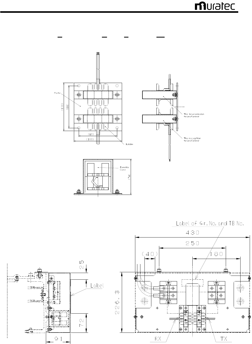
3.3.3. CMC-TR
(Communication Modem Controller :TRansformer)
Transmission transformer overlays the signals from CMC-BM onto the non-conductive power line
or signal line.
The reception transformer receives the signals from vehicles overlaid in the non-conductive
power line or signal line.
Figure 9 shows the outer forms of the transformers.
Muratec Automation Co., Ltd.
Muratec Automation Co., Ltd.Muratec Automation Co., Ltd.
Muratec Automation Co., Ltd.
12
3.4. The Block Diagram of CMC
Fig. 4 The block diagram of CMC
CMC is a communication unit between a vehicle controller and vehicles.
The communication signals modulate current signals of a power line/or signal line .
The vehicle controller controls vehicle movement by transmitting and receiving this signal.
[CMC-BC]
Communication signals from the vehicle controller are transmitted to CMC-BC as RS232C or
RS485. When communication signal is “1”, The Modulator of CMC-BC modulates 285.7 kHz FSK
signal frequency. When communication signal is “0”, The Modulator of CMC-BC modulates 315.8
kHz FSK signal frequency.
The modulation signal is transmitted to CMC-BM through a line driver of RS485.This modulation
signals transmit to CMC-BM as RS485.
[CMC-BM and CMC-TR]
The modulation signal is received from CMC-BC through a line receiver of RS485.
TX Amp of CMC-BM is full bridge inverter. The modulation signals are converted into a gate
signal of full bridge inverter. The inverter transmits the modulation signal through resonance
circuit and CMC-TR.
Muratec Automation Co., Ltd.
Muratec Automation Co., Ltd.Muratec Automation Co., Ltd.
Muratec Automation Co., Ltd.
13
3.5. Outline form of CMC
3.5.1.
CMC-BC
(Communication Modem Controller :Base Controller)
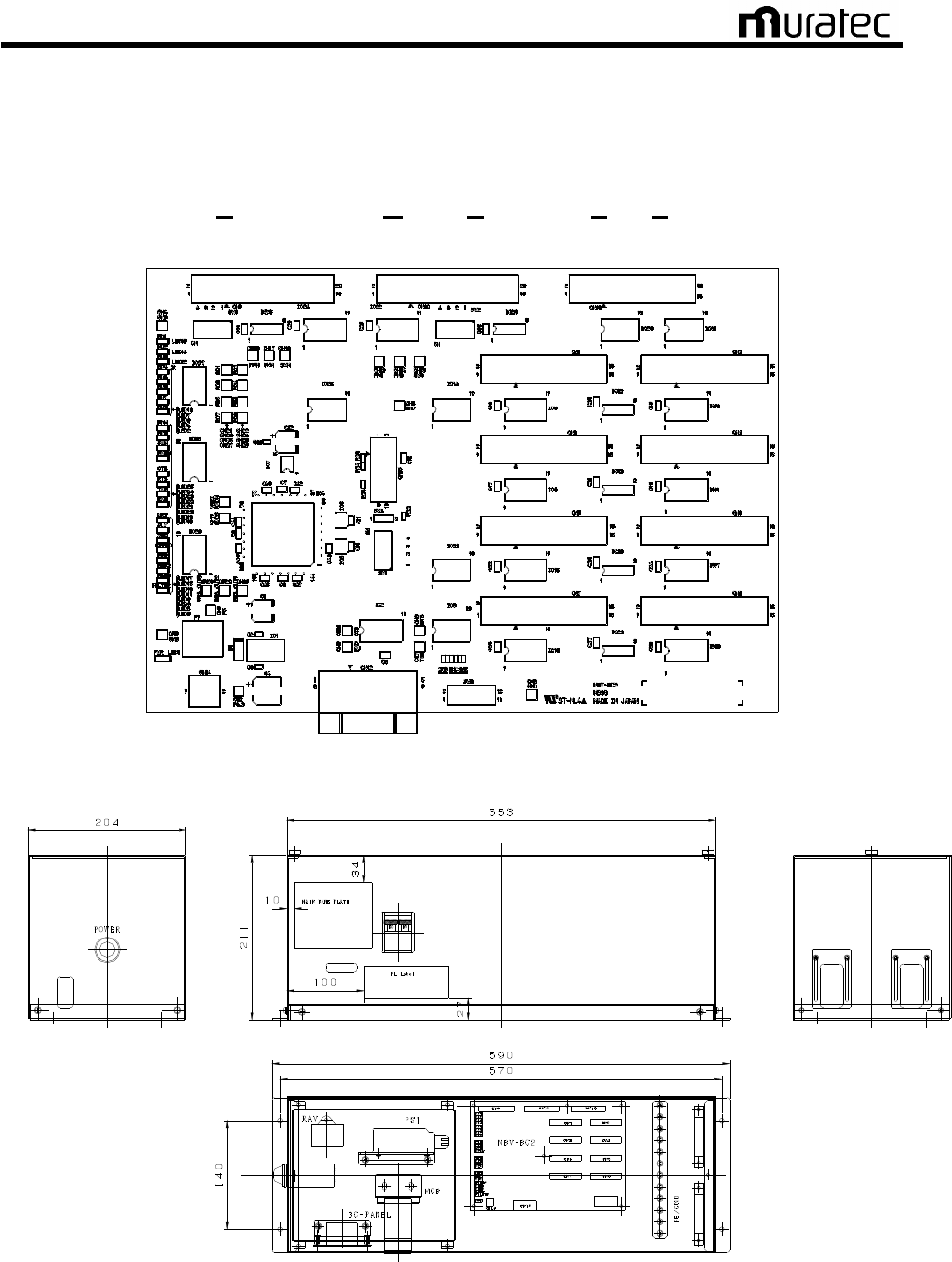
Fig. 5 Outward form of the CMC-BC’s main printed circuit board NBV-BC2
Fig. 6 For example the outward form of the CMC-BC unit

Muratec Automation Co., Ltd.
Muratec Automation Co., Ltd.Muratec Automation Co., Ltd.
Muratec Automation Co., Ltd.
14
3.5.2. CMC-BM
(Communication Modem Controller :Base Modem)
Fig. 7 The outline form of the CMC-BM’s main printed circuit board BV-BM3
Fig. 8 For example the outline form of the CMC-BM unit
Muratec Automation Co., Ltd.
Muratec Automation Co., Ltd.Muratec Automation Co., Ltd.
Muratec Automation Co., Ltd.
15
3.5.3.
CMC-TR
(Communication Modem Controller :TRansformer)
Fig. 9 The outer forms of the transformers
Fig. 10 For example the outline form of the CMC-TR unit

Muratec Automation Co., Ltd.
Muratec Automation Co., Ltd.Muratec Automation Co., Ltd.
Muratec Automation Co., Ltd.
16
3.6. FCC standard
The transmission assembly in the communication unit CMC meets FCC Part15 Subpart C as the
intentional radiator.
FCC ID of CMC: ZBQVEHICLECMC
FCC WARNING
Changes or modifications not expressly approved by the party responsible for compliance could
void the user’s authority to operate the equipment.
- Properly shielded and grounded cables and connectors must be used for connection to
vehicle controller and CMC-BC in order to meet FCC emission limits.
- Properly shielded and grounded cables and connectors must be used for connection to
CMC-BM and CMC-BC in order to meet FCC emission limits.
- TX transformer of CMC-TR with ferrite core must be used for RF interference suppression.
Note:
This equipment has been tested and found to comply with the limits for a Class A digital device,
pursuant to part 15 of the FCC Rules. These limits are designed to provide reasonable
protection against harmful interference when the equipment is operated in a commercial
environment. This equipment generates, uses, and can radiate radio frequency energy and, if
not installed and used in accordance with the instruction manual, may cause harmful
interference to radio communications. Operation of this equipment in a residential area is likely
to cause harmful interference in which case the user will be required to correct the interference
at his own expense.
[Note.1]
The FCC certificate position may vary because different case materials and shapes are adopted
for different customers.

Muratec Automation Co., Ltd.
Muratec Automation Co., Ltd.Muratec Automation Co., Ltd.
Muratec Automation Co., Ltd.
17
4. CMC-BC Board Setting
4.1.
CMC-BC Board Check
4.1.1.
Purpose
Check for short circuit and earth ground fault before energizing CMC-BC board for the safety.
4.1.2. Required Materials
• Wiring Diagrams, Checklist
• Multimeter, Phillips-head Screw Driver (+2), Wrench, Tape Measure
• Vehicle
4.1.3. Tips, Precautions and Prohibited Actions
<Precautions>
・ Set the barricade with colored-cones and safety bars around the work area.
・ Measure the short-circuit and the earth fault after confirming it has no voltage.
<Prohibited Actions>
・ Work in the energized status is prohibited.
4.1.4. Procedures
A) After confirming that the CMC-BC board’s CPM is OFF (see Fig. 11), check for short circuit
and earth ground fault on the secondary side of the CPM. (Make sure you confirm that the
AC power voltage is zero V before measuring the resistance. Since the primary side of the
CMP is connected to the indicator lamps, short circuit check should show 3 - 4KΩ. The
ground fault shall be open.)
B) Check for short circuit and earth ground fault on the secondary side of CP1 through CP8.
The CPM must be OFF at this time. Both short circuit and earth ground fault checks on the
secondary side of CP1 through CP 8 shall indicate open.
C) Confirm that all connectors on the NBV-BC printed circuit board are firmly connected. Lock
the connecters with connector fastenings. (If any connecter is loose, communications will
fail.)
D) Firmly insert the 232C cable from the OHVC to CN12 on the NBV-BC printed circuit board.
(If loose, communications will fail.)
E) Set the NBV-BC P board’s DIP switches (SW 1, 2 and 3) in accordance with provided
specifications. (If they are not set, communications will fail.)
F) Measure the voltage of primary side of CPM
G) After confirming that everything is good, turn ON the circuit breaker on the power distribution
panel to energize the CMC-BC board.
<Prohibited Actions>
Hereafter, Work in the energized status is prohibited.
Muratec Automation Co., Ltd.
Muratec Automation Co., Ltd.Muratec Automation Co., Ltd.
Muratec Automation Co., Ltd.
18
Fig. 11
For example the outward form of the CMC-BC unit
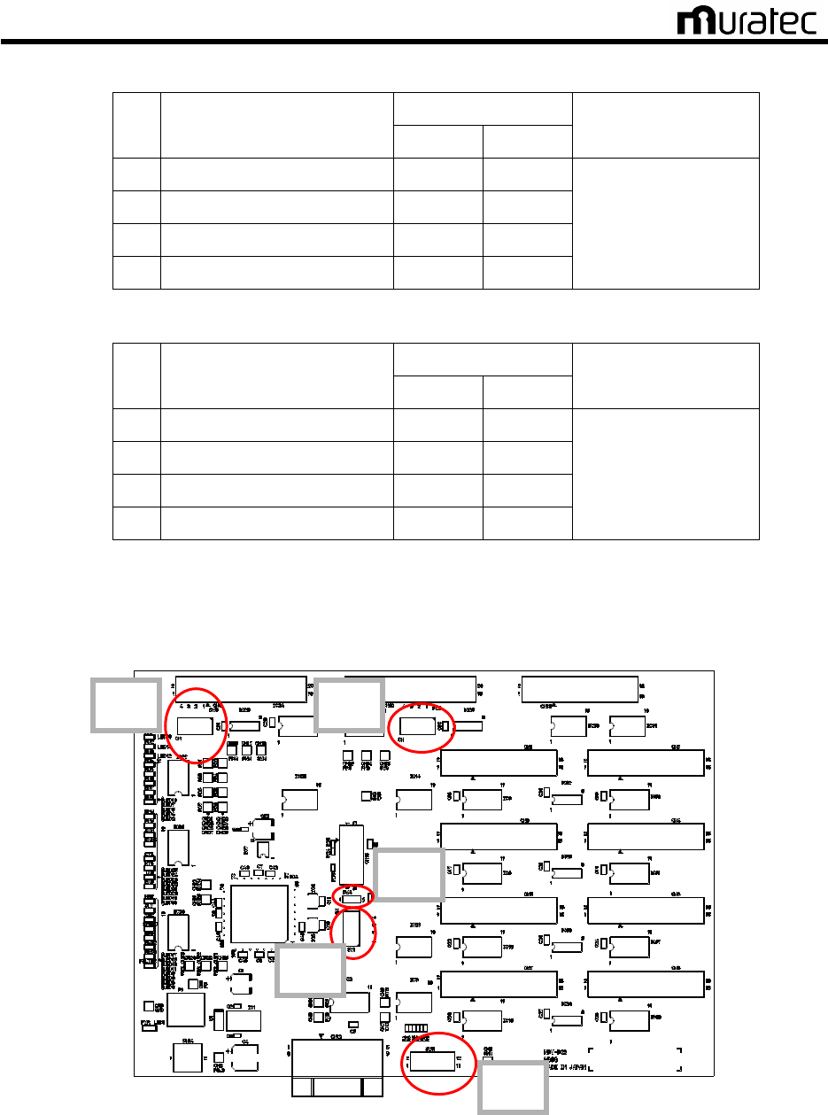
4.2. NBV-BC Printed Circuit Board DIP Switch Settings
4.2.1. Purpose
Set the station number etc. on site as when it is shipped with the initial settings.
4.2.2. Required Materials
• Connection Diagram, Checklist
• Precise Driver
4.2.3. Tips, Precautions and Prohibited Actions
<Precautions>
・ Appropriate settings are required for an appropriate BC. Otherwise, it will not
communicate with.
4.2.4. Procedures
A) The settings for the NBV-BC’s DIP-SWs are shown below. Refer to examples 1 through 4
to properly set up the target module.
Table. 1 DIPSW-1(Operation Mode)
Operation
SW
Function
OFF ON
Remarks
1
Master/Slave Switch Slave Master
2 Filter Enable/Disable Switch Enable Disable
3 RS232C/RS485 Switch RS232C RS485
Available only in Master
4 Communications Speed Switch
19.2 Kbps
28.8 Kbps
See specifications
Muratec Automation Co., Ltd.
Muratec Automation Co., Ltd.Muratec Automation Co., Ltd.
Muratec Automation Co., Ltd.
19
Table. 2 DIPSW-2(Terminal Resistance Settings)
Operation
SW
Function
OFF ON
Remarks
1
Terminal Resistance Y/N No Yes
2 Terminal Resistance Y/N No Yes
3 Terminal Resistance Y/N No Yes
4 Terminal Resistance Y/N No Yes
Refer to connection
sample
Table. 3 DIPSW-3(Terminal Resistance Settings)
Operation
SW
Function
OFF ON
Remarks
1
Terminal Resistance Y/N No Yes
2 Terminal Resistance Y/N No Yes
3 Terminal Resistance Y/N No Yes
4 Terminal Resistance Y/N No Yes
Refer to connection
sample
B) NBV-BC printed circuit board DIP-SW layout and connector layout are shown in the figure
below.
Fig. 12 NBV-BC Board Switch Layout
SW5
SW3
SW2
SW5
SW1
CN9
CN
10
CN
13
CN1 CN2
CN
3
CN
4
CN5 CN6
CN
7
CN
8
CN12
CN
1
4
Muratec Automation Co., Ltd.
Muratec Automation Co., Ltd.Muratec Automation Co., Ltd.
Muratec Automation Co., Ltd.
20
CMC-BC (Single use)
OHVC
CN12
CN13
CN9 CN10
RS232C
※
RS485
Master
MasterMaster
Master
CMC-BC (2 in use)
)
OHVC
CN12
CN13
CN9 CN10
RS232C
※
RS485
Master
MasterMaster
Master
CN9 CN10
Slave 1
Slave 1Slave 1
Slave 1
CMC-BC (N in use)
)
OHVC
CN12
CN13
CN9 CN10
※
RS485
Master
MasterMaster
Master
CN9 CN10
Slave 1
Slave 1 Slave 1
Slave 1 -
--
- Slave (N
Slave (N Slave (N
Slave (N-
--
-1)
1)1)
1)
CN9 CN10
Slave N
Slave NSlave N
Slave N
※ With RS485 (CN13), set DIPSW1-3 ON
Fig. 13 NBV-BC Board Connection
Table. 4
CMC-BC DIP Switch Settings (Filter “Enable”, communication speed:28.8kbps)
DIP SW1 DIP SW2 DIP SW3
BC
Master/
Slave No.
ON
OFF
No.
ON
OFF
No.
ON
OFF
SW4
SW5
1 ○
1
○ 1
○
2 ○
2
○ 2
○
3 ○
3
○ 3
○
1 Master
4 ○
4
○ 4
○
Open
ALL
Close
1 ○
1 ○
1
○
2 ○
2 ○
2
○
3 ○
3 ○
3
○
Master
4 ○
4 ○
4
○
Open
ALL
Close
1
○ 1
○ 1 ○
2 ○
2
○ 2 ○
3 ○
3
○ 3 ○
2
Slave
4 ○
4
○ 4 ○
Open
ALL
Close
1 ○
1 ○
1
○
2 ○
2 ○
2
○
3 ○
3 ○
3
○
Master
4 ○
4 ○
4
○
Open
ALL
Close
1
○ 1 ○
1 ○
2 ○
2 ○
2 ○
3 ○
3 ○
3 ○
Slave1
-
Slabe (N-1)
4 ○
4 ○
4 ○
Open
ALL
Close
1
○ 1
○ 1 ○
2 ○
2
○ 2 ○
3 ○
3
○ 3 ○
N
Slave N
4 ○
4
○ 4 ○
Open
ALL
Close

Muratec Automation Co., Ltd.
Muratec Automation Co., Ltd.Muratec Automation Co., Ltd.
Muratec Automation Co., Ltd.
21
Table. 5
CMC-BC DIP Switch Settings (Filter “Enable”, communication speed:19.2kbps)
DIP SW1 DIP SW2 DIP SW3
BC
Master/
Slave No.
ON
OFF
No.
ON
OFF
No.
ON
OFF
SW4
SW5
1 ○
1
○ 1
○
2 ○
2
○ 2
○
3 ○
3
○ 3
○
1 Master
4 ○
4
○ 4
○
Open
ALL
Close
1 ○
1 ○
1
○
2 ○
2 ○
2
○
3 ○
3 ○
3
○
Master
4 ○
4 ○
4
○
Open
ALL
Close
1
○ 1
○ 1 ○
2 ○
2
○ 2 ○
3 ○
3
○ 3 ○
2
Slave
4 ○
4
○ 4 ○
Open
ALL
Close
1 ○
1 ○
1
○
2 ○
2 ○
2
○
3 ○
3 ○
3
○
Master
4 ○
4 ○
4
○
Open
ALL
Close
1
○ 1 ○
1 ○
2 ○
2 ○
2 ○
3 ○
3 ○
3 ○
Slave1
-
Slabe (N-1)
4 ○
4 ○
4 ○
Open
ALL
Close
1
○ 1
○ 1 ○
2 ○
2
○ 2 ○
3 ○
3
○ 3 ○
N
Slave N
4 ○
4
○ 4 ○
Open
ALL
Close
4.2.5. Judgment
It passes if all of adjustments are performed and confirmed.

Muratec Automation Co., Ltd.
Muratec Automation Co., Ltd.Muratec Automation Co., Ltd.
Muratec Automation Co., Ltd.
22
5. CMC-BM Board Setting
5.1. CMC-BM Board Check
5.1.1. Purpose
Check for short circuit and earth ground fault before energizing CMC-BC board for the safety.
5.1.2. Required Materials
• Wiring Diagrams, Checklist
• Multimeter, Phillips-head Screw Driver (+2)
5.1.3. Tips, Precautions and Prohibited Actions
<Precautions>
・ Strictly adhere to safety rules for high-place work.
・ Measure the short-circuit and the earth fault after confirming it has no voltage.
<Prohibited Actions>
・ Work in the energized status is prohibited.
5.1.4. Procedures
A) Check for short circuit and earth ground fault on the secondary side of the circuit breaker
(see Fig. 14) on the CMC-BM board. Shut off the power for CP1 through 8 of CMC-BC.
Since the line is connected to indicator lamp, short circuit check should show 3-4 kΩ. Earth
ground fault shall be open.
B) Check for short circuit and earth ground fault on the secondary side of the circuit breaker for
CP2 through CP5. (Both short circuit and earth ground shall be open.)
C) Check for short circuit and earth ground fault on the secondary side of the TB2. (Earth
ground shall be open.)
D) When all checks are in good conditions, turn on a circuit breaker for CMC-BC, and it
energize the BM board.
<Prohibited Actions>
Thereafter, work in the energized status is prohibited.

Muratec Automation Co., Ltd.
Muratec Automation Co., Ltd.Muratec Automation Co., Ltd.
Muratec Automation Co., Ltd.
23
Fig. 14
For example the outward form of the CMC-BM unit
5.1.5. Judgment
It passes if all of adjustments are performed and confirmed.

Muratec Automation Co., Ltd.
Muratec Automation Co., Ltd.Muratec Automation Co., Ltd.
Muratec Automation Co., Ltd.
24
6. Communications Adjustment
6.1. Prerequisites
A) Power supply panel start-up adjustments are complete.
B) All the CMC boards and all the power supply panels have been started up.
C) All the wiring of feeder cables (included dedicated communications lines) is appropriate.
Especially perform a check the U/V direction using communications direction checker.
D) When OHVC, EPLC and the vehicle are all able to be powered up, turn the power on to all
the equipment, then check the communications status between each device. Check that
the power lamp is on for all devices.
E) No workers are near the tracks.
* Communications Flow
OHVC ←→ CMC-BC ←→ CMC-BM ←→ CMC-TR ←→
Track (Power feeder cables or communications wires) ←→ Vehicle
6.2. Check before Vehicle Start-Up (Track Power Panel is OFF)
6.2.1. Purpose
Check for the communication condition when track power panel is OFF.
6.2.2. Required Materials
• Feeder Cable Layout Drawings, Wiring Diagrams, Checklist
• Phillips-head Screw Driver (+2)
6.2.3. Tips, Precautions and Prohibited Actions
<Precautions>
・ Strictly adhere to safety rules for high-place work.
<Prohibited Actions>
・ Work in the energized state is prohibited.
6.2.4. Procedures
A) Turn on all of CMC-BC and CMC-BM. Turn off the entire track power panel.
B) Check that LED1~8 of the CMC-BC’s NBV-BC board are not lit.
If any of LED1~8 is lit, refer to the troubleshooting guide.

Muratec Automation Co., Ltd.
Muratec Automation Co., Ltd.Muratec Automation Co., Ltd.
Muratec Automation Co., Ltd.
25
Fig. 15 CMC-BC Board’s NBV-BC
6.3. Check before Vehicle Start-Up (Track Power Panel is ON)
6.3.1. Purpose
Check for the communication condition when track power panel is ON and no vehicles on the
track.
6.3.2. Required Materials
• Feeder Cable Layout Drawings, Wiring Diagrams, Checklist
• Phillips-head Screw Driver (+2)
6.3.3. Tips, Precautions and Prohibited Actions
<Precautions>
・ Strictly adhere to safety rules for high-place work.
<Prohibited Actions>
・ Work in the energized state is prohibited.
6.3.4. Procedures
A) Turn on the electrical power board, and all of CMC-BC and CMC-BM.
B) Check that LED1~8 of the CMC-BC’s NBV-BC board are not lit.
C) If any of LED1~8 is lit, refer to the troubleshooting guide.
LED1-8
CN1 CN2
CN3 CN4
CN5 CN6
C
N
7
CN
8
CN
12
CN
1
4

Muratec Automation Co., Ltd.
Muratec Automation Co., Ltd.Muratec Automation Co., Ltd.
Muratec Automation Co., Ltd.
26
6.4. Check and Adjustments of each Level of CMC-BM
6.4.1. Purpose
Check for the communication condition between one vehicle and the OHVC.
6.4.2. Required Materials
• Feeder Cable Layout Drawings, Wiring Diagrams, Checklist
• Oscilloscope, Phillips-head Screw Driver (+2)
6.4.3. Tips, Precautions and Prohibited Actions
<Precautions>
・ Strictly adhere to safety rules for high-place work.
<Prohibited Actions>
・ Work in the energized state is prohibited.
6.4.4. Procedures
Check and adjust the waveforms of all CMC-BM. Record the noise level, reception waveform
level, and squelch.
In order to check the difference in reception levels according to location, check these 3 places in
order: 1) next to the communications transformer 2) next to the INPUT 3) next to RETURN.
Also, to make the waveform check as accurate as possible, use the same vehicle.
If the noise level is 0.5V or more, refer to the troubleshooting guide, take countermeasures, then
record the capacity of the coaxial cable entrance capacitor after adjustments.
A) Check with an installed vehicle
<Attention>
Operate a vehicle and a maintenance lifter referring to the vehicle installation/removal instructions.
(1) Set the vehicle to AUTO MODE.
(2) Send an initial wait command from OHVC.
If communications are not established with the vehicle, refer to the troubleshooting
guide.
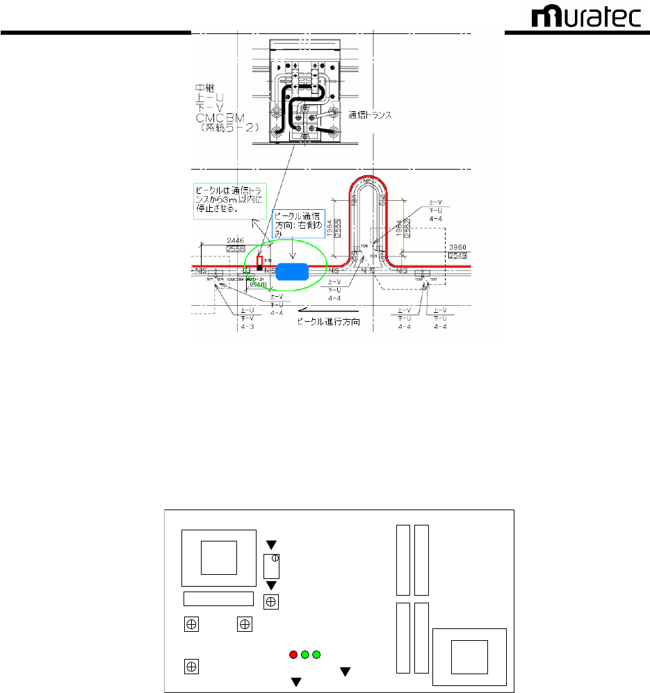
B) Receiving waveform check (By communications transformer)
(1) Move a vehicle to a location By a communications transformer as shown in the figure
below. Using the remote control, switch the vehicle communications side to
transformer side only. Check feeder cable layout in provided feeder cable layout
drawing.
Muratec Automation Co., Ltd.
Muratec Automation Co., Ltd.Muratec Automation Co., Ltd.
Muratec Automation Co., Ltd.
27
Fig. 16
Positioning OHV (By Communications Transformer)
(2) Procedures for receiving waveform check of BV-BM3 are as follows.
Connect an oscilloscope to BV-BM3 and monitor receiving waveform.
+ side: CH201 (CMP_IN)
- side: CH100 or CH101 (0V)
VR1
VR2 VR200
VR201
CH201:CMP_IN
CH202:TH_L
VR202
CH101:0V
CH100:0V
LED3 1 2
Fig. 17
BV-BM3 Check Pin Arrangement
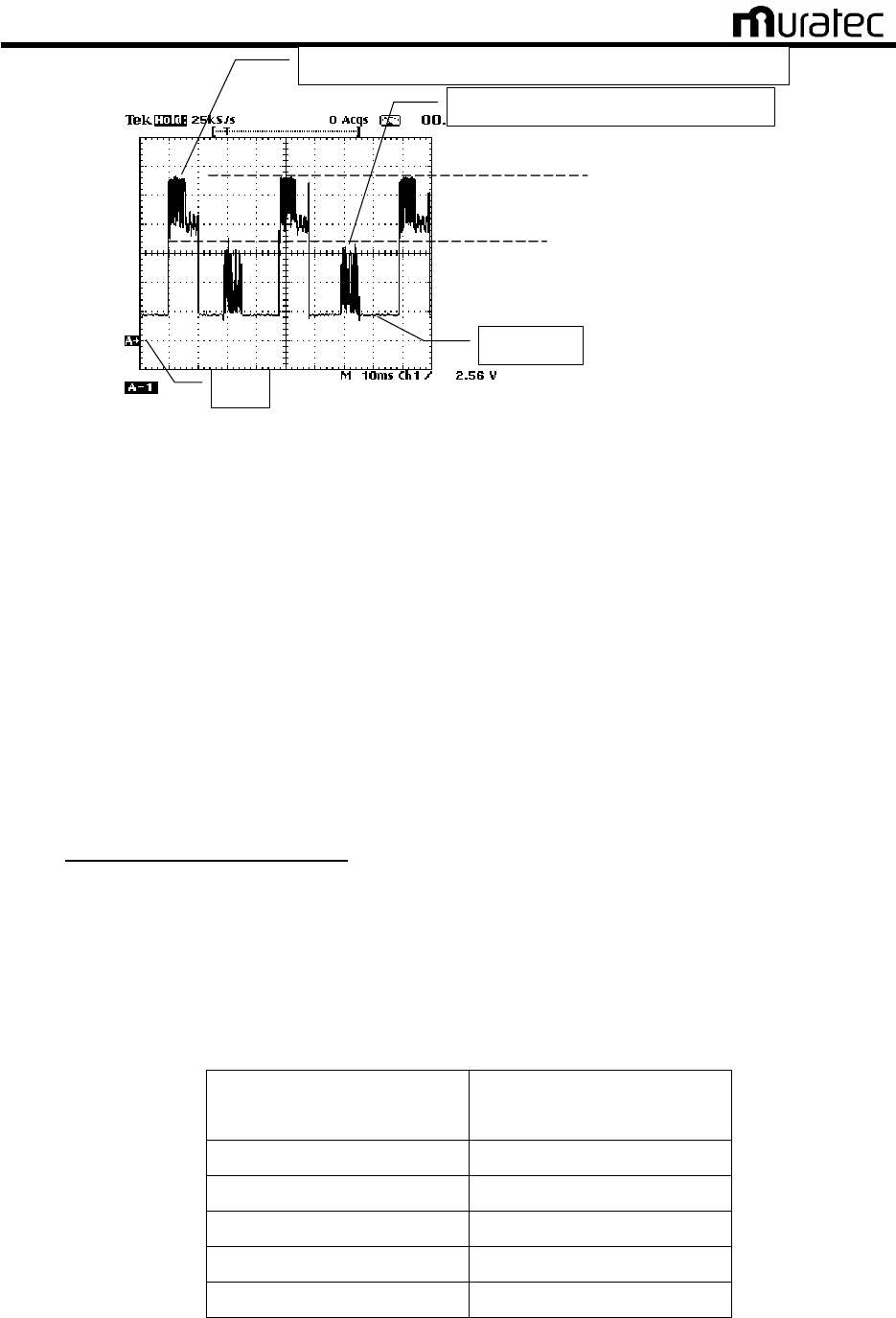
(3) Monitor the minimum receiving waveform and the maximum noise level.
Range: 1V ~ 2V/DIV, 10mS ~ 20mS/DIV
Maximam Noise Level Communication Speed 19.2kbps・・・ 1.0V or below.
28.8kbps・・・ 0.5V or below.
Muratec Automation Co., Ltd.
Muratec Automation Co., Ltd.Muratec Automation Co., Ltd.
Muratec Automation Co., Ltd.
28
Comm. signal (receiving waveform) from OHV -> CMC (OHVC)
Comm. signal form CMC (OHVC) -> OHV
Noise level
0V
B. Min. receiving waveform
A. Max. receiving waveform
Fig. 18 Receiving Waveform
(4) Procedures for BV-BM3 receiving waveform adjustment are as follows.
Adjust the waveform level with variable resistance (VR1, VR2, VR200 and VR202) as
you monitor the receiving waveform. Adjust variable resistance per one division in
order of VR1→VR2→VR200→VR201.
Receiving waveform criteria;
Minimum level of receiving waveform communication speed :19.2kbps 7V±0.5V
28.8kbps 3V±0.5V
Squelch level 1.5V±0.5V
* If the receiving level does not decrease, rotate all variable resistance fully counter-clockwise.
* Lines with communication wires
If the receiving level does no decrease to the specified value, decrease the number of
communication wire turns on the communications transformer. In case the minimum
receiving level is 2V or less, increase the number of communication wire turns on the
communications transformer.
Table. 6
Communication Wire Turns on Communications Transformer
Ded. Comm. Line: Length
(One way)
Turn Count to Comm.
Transformer
30m 1 turn
60m 2 turns
90m 3 turns
120m 4 turns
150m 5 turns
Muratec Automation Co., Ltd.
Muratec Automation Co., Ltd.Muratec Automation Co., Ltd.
Muratec Automation Co., Ltd.
29
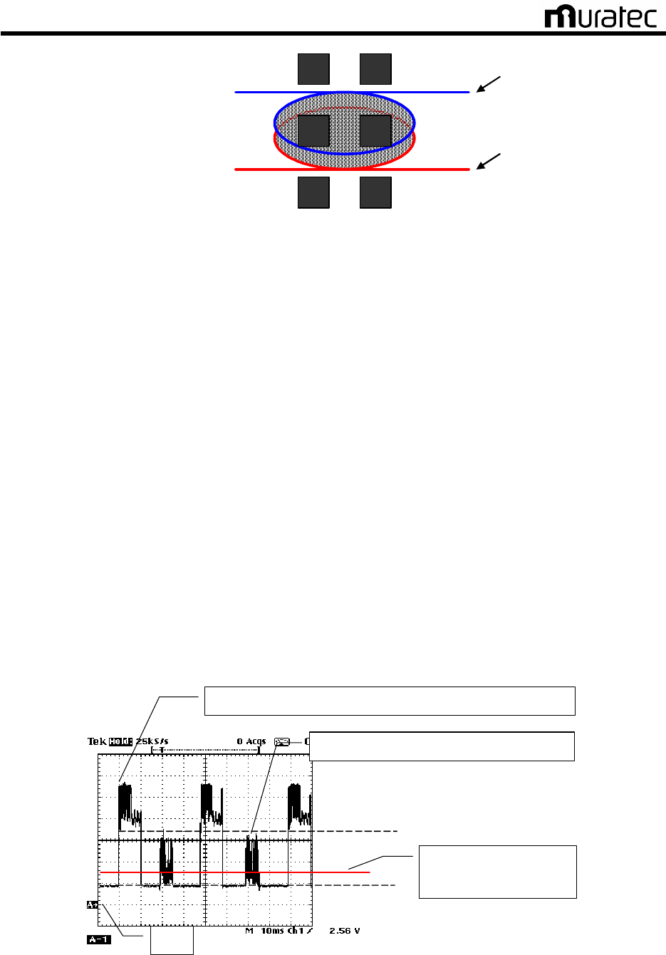
Dedicated Comm. Line U Side
Communication Transformer
Dedicated Comm. Line V Side
<
<<
<3 Turn Definition
3 Turn Definition3 Turn Definition
3 Turn Definition>
>>
>
Fig. 19
Settings of Dedicated Communications Line (to the Communications Transformer) Turn Count
(5) Record the minimum receiving waveform and maximum noise level after adjustment.
Save the reception waveform on the oscilloscope. Input the saved graphics to the PC,
and save them so that which system has which graphics is understood.
C) Squelch check and adjustment
(1) Adjust BV-BM3 squelch following the steps below.
(2) Connect an oscilloscope to BV-BM3 and monitor squelch.
+ side: CH202 (TH_L)
- side: CH100 or CH101 (0V)
Range: 1.0V/DIV, 10mS ~ 20mS/DIV
(3) Adjust squelch level with the volume (VR202).
Squelch level criteria;
Minimum level of receiving waveform communication speed:19.2kbps 7V±0.5V
28.8kbps 3V±0.5V
Squelch level 1.5V±0.5V
(4) Record the adjusted squelch level.
Communications signal (Receiving Waveform): OHV ? CMC (OHVC)
Communications signal: CMC (OHVC) ? OHV
0 V
Min. level of receiving waveform
Noise level
Adjust squelch level to
1.5V±0.5V
Fig. 20
Squelch Adjustments
Muratec Automation Co., Ltd.
Muratec Automation Co., Ltd.Muratec Automation Co., Ltd.
Muratec Automation Co., Ltd.
30
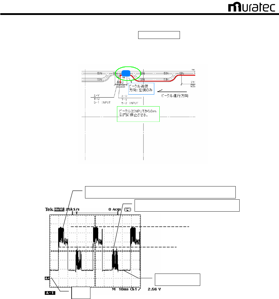
D) Receiving Waveform Check (Next to INPUT)
(1) Move the vehicle to coaxial cable’s Next to INPUT. Using the remote control, switch
the vehicle’s communications direction to the coaxial cable’s INPUT side. Check the
feeder cable arrangement on the Feeder Cable Arrangement Map.
Fig. 21
Example of OHV Arrangement (By INPUT)
Communications Signal (Reception Waveform): Vehicle → CMC (OHVC)
Communications Signal: CMC (OHVC) → Vehicle
Noise Level
0V
B Reception Waveform Lowest Value
A Reception Waveform Greatest Value
Fig. 22
Receiving Waveform
(2) Monitor the minimum receiving waveform and the maximum noise level.
Range: 1V ~ 2V/DIV, 10mS ~ 20mS/DIV
Maximam Noise Level Communication Speed 19.2kbps・・・ 1.0V or below.
28.8kbps・・・ 0.5V or below.
(3) Record the monitored minimum receiving waveform.
Save the waveform to the oscilloscope and download the saved screen to PC. Save
the screen with an indication showing which line the screen belongs to.

Muratec Automation Co., Ltd.
Muratec Automation Co., Ltd.Muratec Automation Co., Ltd.
Muratec Automation Co., Ltd.
31
E) Receiving waveform check (By RETURN)
(1) Move the vehicle to next to RETURN. Using the remote control, switch the vehicle’s
communications direction to the RETURN side.
Fig. 23 Example of OHV Arrangement (By RETURN)
Communications Signal (Reception Waveform): Vehicle → CMC (OHVC)
Communications Signal: CMC (OHVC) → Vehicle
Noise Level
0V
B Reception Waveform Lowest Value
A Reception Waveform Greatest Value
Fig. 24
Reception Waveform
(2) Monitor the minimum receiving waveform and the maximum noise level.
Range: 1V ~ 2V/DIV, 10mS ~ 20mS/DIV
Maximam Noise Level Communication Speed 19.2kbps・・・ 1.0V or below.
28.8kbps・・・ 0.5V or below.
(3) Record the monitored minimum receiving waveform.
Save the waveform to the oscilloscope and download the saved screen to PC. Save
the screen with an indication showing which line the screen belongs to.
F) Install a cover of the CMC-BM when the adjustment is completed.
G) Check and adjust all CMC-BM.
H) Load the data saved on an oscilloscope to the maintenance PC, and organized the data.
6.4.5. Judgment
It passes if all of adjustments for all CMC-BM are performed or confirmed.

Muratec Automation Co., Ltd.
Muratec Automation Co., Ltd.Muratec Automation Co., Ltd.
Muratec Automation Co., Ltd.
32
7. Specification
Unit name CMC
Baud rate 19.2kbps-38.4kbps
Communication method Serial Communication, Async HDX
Modulation method 2 value FSK(frequency shift keying)
Demodulation method Analog PLL demodulation
Communication Frequency
CMC -> Vehicles:285.7kHz and 315.8 kHz (transmits)
Vehicles -> CMC:342.9 kHz and 363.6 kHz(Receive)
bit error rate < 1×10
-4
Frame error rate < 1×10
-2
7.1. CMC-BC (Communication Modem Controller :Base Controller)
Unit name CMC-BC
Manufacturer MURATEC AUTOMATION CO., LTD.
Weight Approx. 10 kgf *Case materials and shape vary with the system
Size 590mm (W) x 204 mm (L) x 211 mm (H)
*Case materials and shape vary with the system
Power
consumption 10W
Input 1 200V AC 1φ or 100V AC 1φ 50/60Hz
Input 2 Vehicle controller―CMC-BC RS232C/RS485
Output 1 CMC-BC―CMC-BM RS485 8 ports max.
Output 2 CMC-BC―CMC-BC RS485 1 port
Output 3 CMC-BC―CMC-BM 200V AC 1φ or 100V AC 1φ 50/60Hz
7.2. CMC-BM(Communication Modem Controller :Base Modem)
Unit name CMC-BM
Manufacturer MURATEC AUTOMATION CO., LTD.
Weight Approx.7kgf *Case materials and shape vary with the system
Size 613mm (W) x 266 mm (L) x 71 mm (H)
*Case materials and shape vary with the system
Power
consumption 20W
Input 1 CMC-BC―CMC-BM 200V AC 1φ or 100V AC 1φ 50/60Hz
Input 2 CMC-BC―CMC-BM RS485
Input 3 CMC-TR―CMC-BM Analog signal 4 ports max.
Output 1 CMC-BM―CMC-TR Analog signal 2 ports max.

Muratec Automation Co., Ltd.
Muratec Automation Co., Ltd.Muratec Automation Co., Ltd.
Muratec Automation Co., Ltd.
33
7.3. CMC-TR(Communication Modem Controller :TRansformer)
Unit name CMC-TR
Manufacturer MURATEC AUTOMATION CO., LTD.
Weight Approx. 5 kgf *Case materials and shape vary with the system
Size 430 mm (W) x 226 mm (L) x 91 mm (H)
*Case materials and shape vary with the system
Power
consumption
MAX 1W
*When communication signal transmitted through the non-conductive power
line
Input 1 CMC-BM―CMC-TR Analog signal
Output 1 CMC-TR―CMC-BM Analog signal

Muratec Automation Co., Ltd.
Muratec Automation Co., Ltd.Muratec Automation Co., Ltd.
Muratec Automation Co., Ltd.
34
8. Error process
[Note.1]
Before servicing CMC-BC,CMC-BM,CMC-TR,always shut off the power supply.
[Note.2]
If the communication signals are overlaid onto the non-conductive power line, also shut off the
power source of the non-conductive power line before starting maintenance on CMC-BM and
CMC-TR.
<Communication error trouble shooting>
Vehicle Controller issues a communication error
Is Vehicle Controller sending communication signals?
Check the settings for Vehicle Controller.
Are the power indicator lights of CMC-BC and CMC-BM illuminated?
Is the power supply of 200V AC 1φor 100V AC 1φ50/60Hz connected?
Is the input fuse burnt?
Replace the fuse.
Turn the power supply OFF. Is the input resistance of the DC
power almost 0 ohm?
Replace the DC power supply.
Is the power LED of the print circuit NBV-BC illuminated?
Is the power LED of the print circuit BV-BM2 illuminated?
Replace the print circuit board
Is the connection between CMC-BM and CMC-TR normal?
Restore connection.
END