NEC of America 58155 NEC NLite E 155 MB 5.8 GHz Digital Microwave Radio User Manual Part 1
NEC Corporation of America NEC NLite E 155 MB 5.8 GHz Digital Microwave Radio Part 1
Contents
- 1. User Manual Part 1
- 2. User Manual Part 2
- 3. User Manual Part 3
- 4. User Manual Part 4
- 5. User Manual Part 5
User Manual Part 1


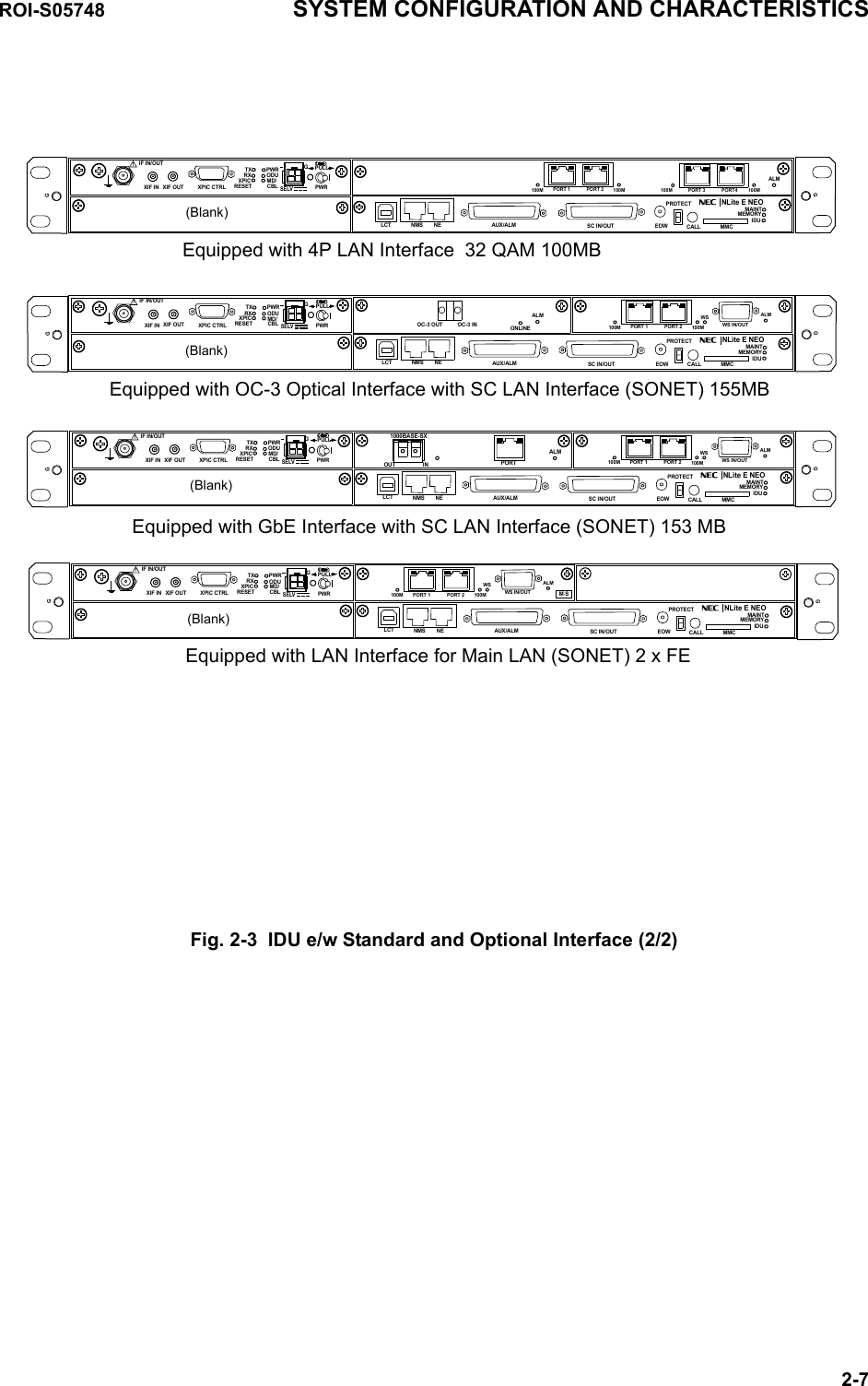
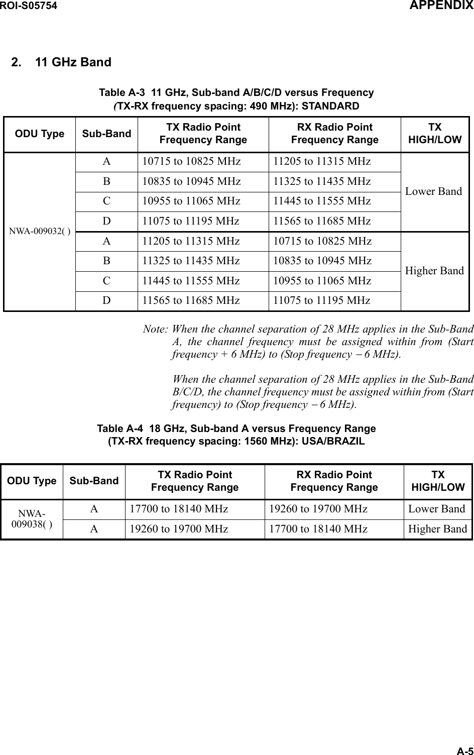
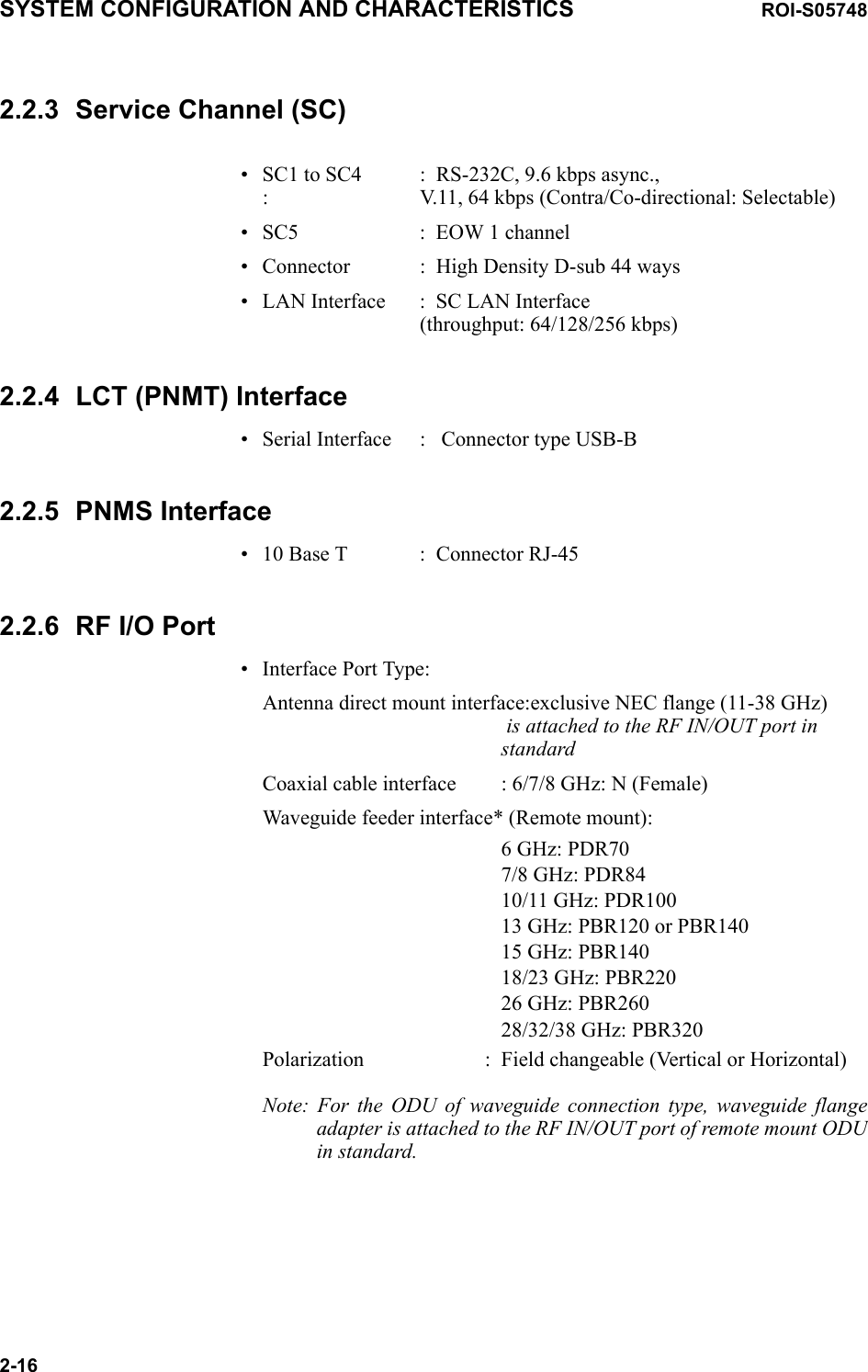
![(3) 4 Port LAN Table 2-1 4 Port LAN 100 Mbps (32QAM)LAN Setting Capacity *Port 1 Port 2 Port 3 Port 4 LAN [Mbps]P1 - P4 = 100 M shared 100P1 & P2=50M separated P3 & P4=50M separated 100P1 = 25M separatedP2 = 25M separatedP3 = 25M separatedP4 = 25M separated100Disabled Disabled Disabled Disabled 0ROI-S05748 SYSTEM CONFIGURATION AND CHARACTERISTICS2-15Note: * Total capacity: 108 Mbps.2.2.2 LAN Interface (1000 Base-SX/1000 Base-T) (GbE)Table 2-2 GbE LANType 1000 Base-SX (IEEE 802.3z) 1000 Base-T (IEEE 802.3ab)Throughput 150 Mbps 150 MbpsConnector type LC RJ-45Port Number 1 port 1 port](https://usermanual.wiki/NEC-of-America/58155.User-Manual-Part-1/User-Guide-1070882-Page-22.png)
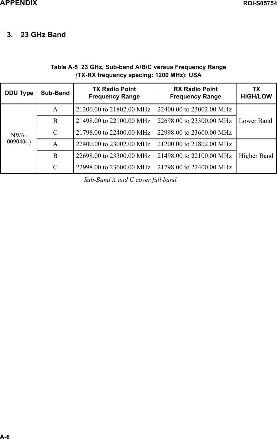
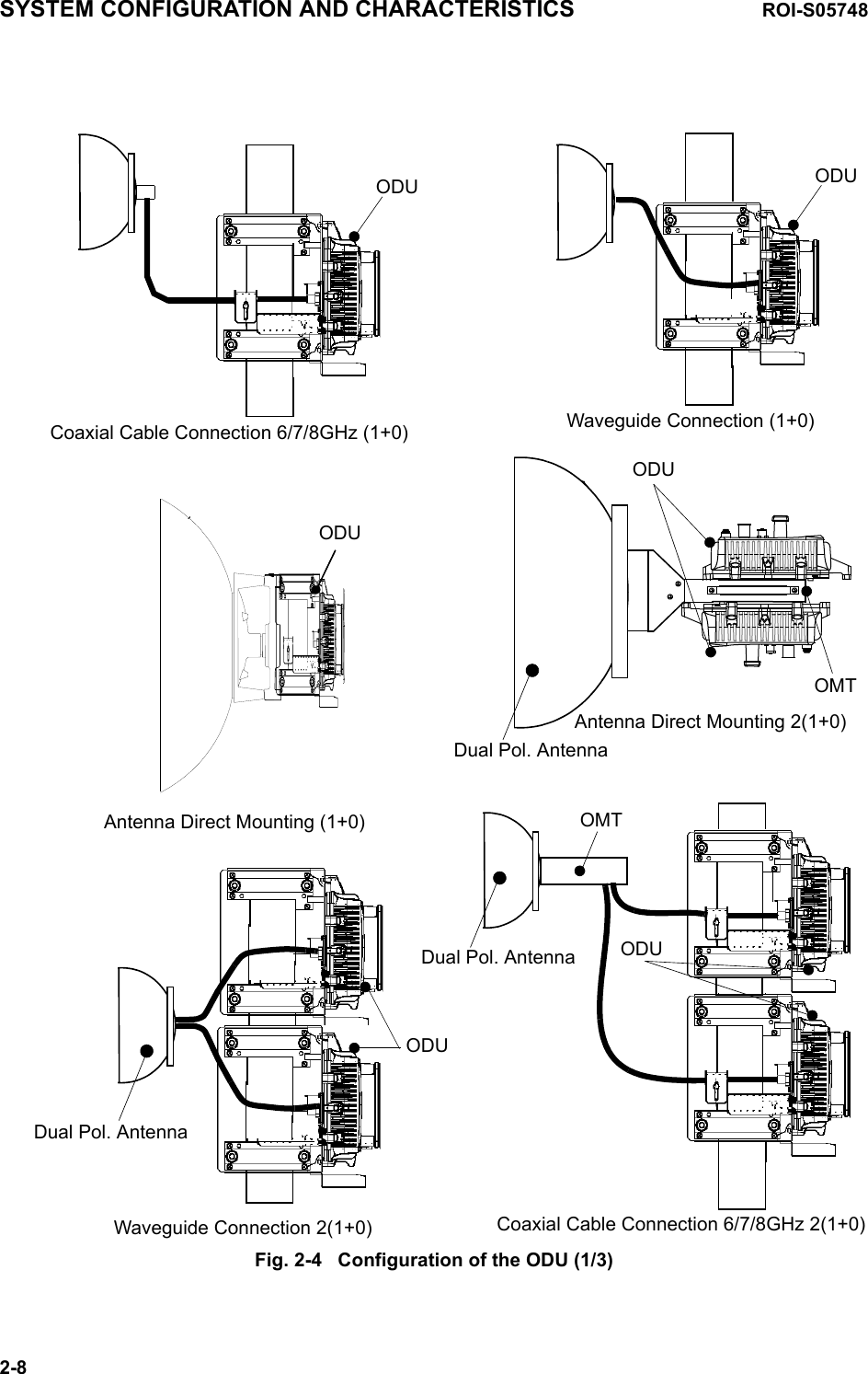
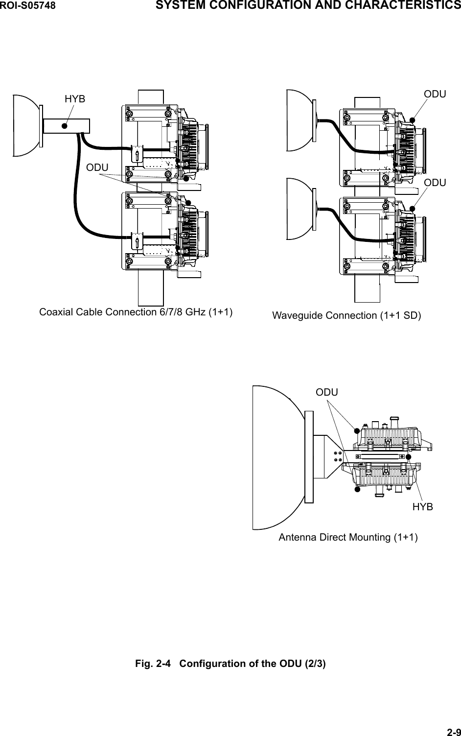
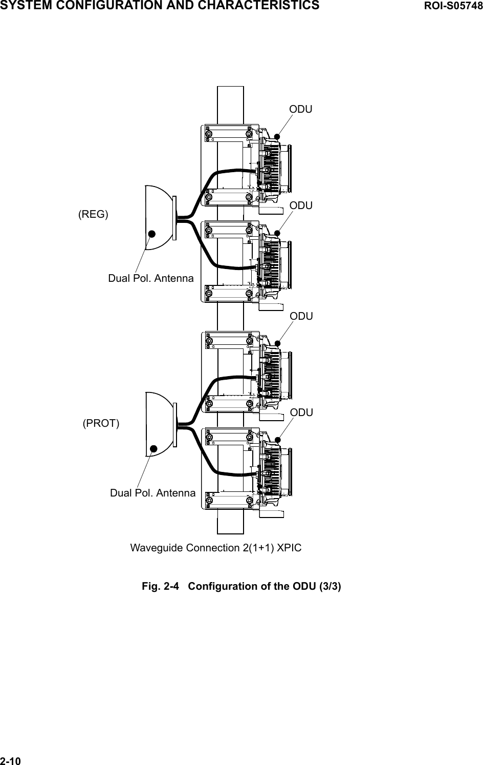
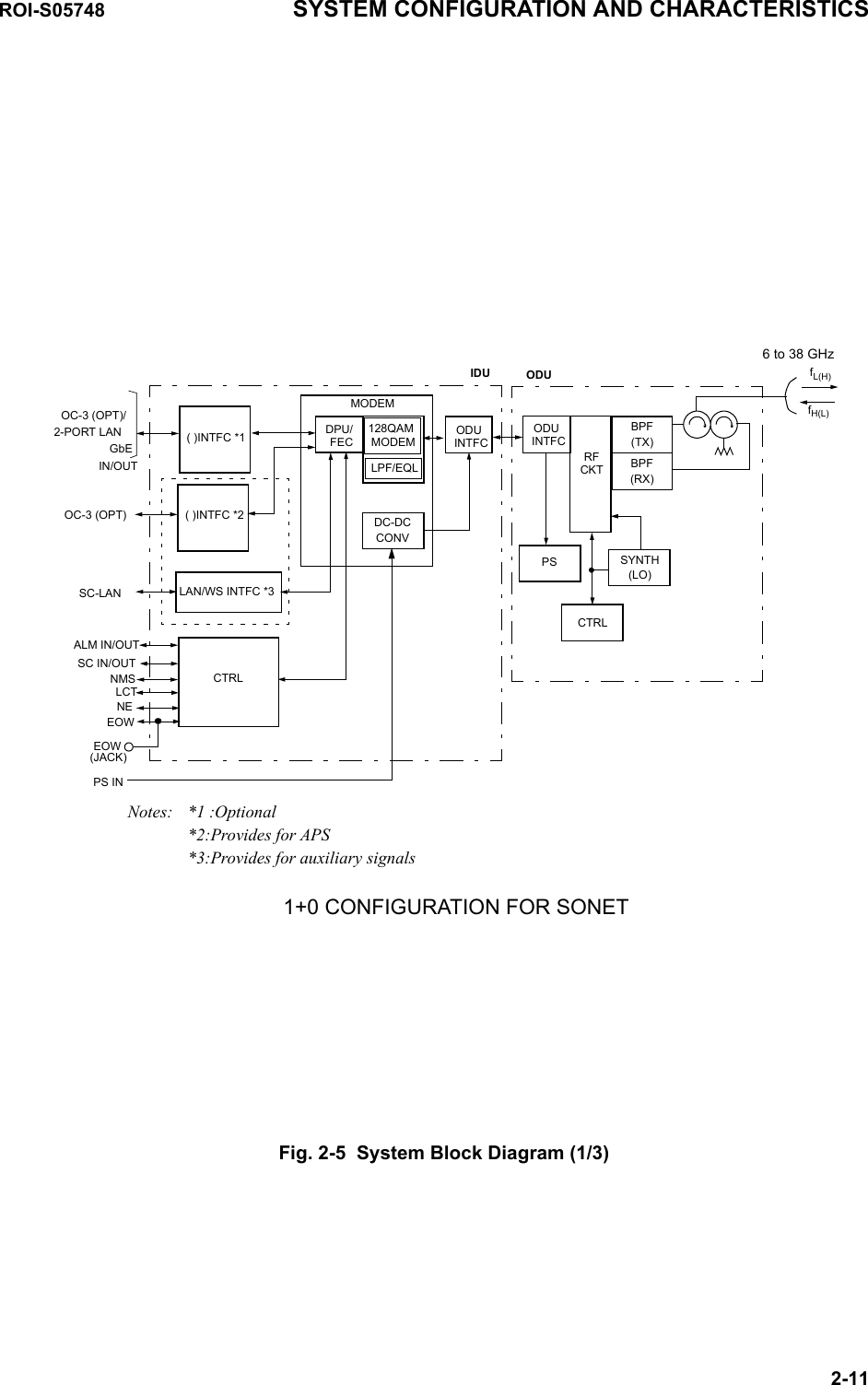
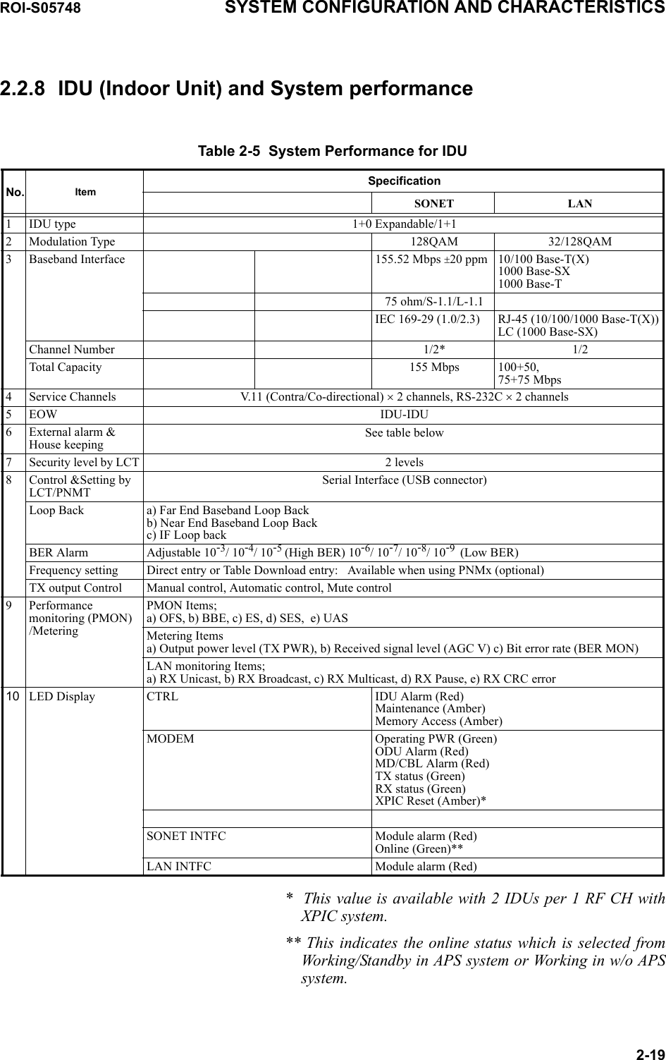
![Table 2-3 System Performance for 32QAM/ODUFrequency Band (GHz) 67-8 10-11 13 15 18 23 26 28 32 38 GuaranteedRange [GHz] 5.925-7.117.12-8.510.15-11.712.75-13.2514.25-15.3517.7-19.721.3-23.624.25-27.527.5-29.531.8-33.437.0-40.0−InterfacetypeDirect MountN/A N/A NEC Original −Remote mount*2N type or PDR 70N type or PDR 84PDR100PBR120PBR140PBR220PBR220PBR260PBR320PBR320PBR320−Output Power, nominal (dBm) (Measured at ODU output port)+25 +21 +21 +21 +19 +19 +18 +18 +17 +14.5 6-28G:±1.5 dB 32-38G:+1.5/−2.5 dBPower Control (1 dB step, variable)0 to 23 dB*30 to 23 dB*4 ±1.0 dBATPC (1 dB step) 0 to 23 dB*4 −Frequency Stability ± 6 ppm ±10 ppmThreshold Level (dBm), (Measured at ODU input port) at BER = 10-6 +3.0 dBChannel Separation (CS)= 28 (27.5) *1 MHz−75.5 −74.5 −74.5 −75 −75 −74.5 −74.5 −73 −73 73BER = 10-3 Above value −1.5 dBSystem Gain (dB), (Measured at ODU input port) at BER = 10-6−3.0 dBChannel Separation (CS)= 28 (27.5) *1 MHz100.5 95.5 95.5 96 94 94 92.5 92.5 92.5 90 87.5BER = 10-3 Above value +1.5 dBMaximum Input Level −20 dBm for the BER less than 10-3−Residual BER Less than 10-12 at RSL=−30 dBm −ROI-S05748 SYSTEM CONFIGURATION AND CHARACTERISTICS2-17*1 27.5 MHz is applied for 18 GHz.*2 For the ODU of waveguide connection type, flange adapter is attached to the RF IN/OUT port of remote mount ODU in standard.*3 Additional attenuation (5 dB maximum) is available.*4 Additional attenuation is unavailable.2.2.7 ODU (Outdoor Unit) and System Performance](https://usermanual.wiki/NEC-of-America/58155.User-Manual-Part-1/User-Guide-1070882-Page-24.png)
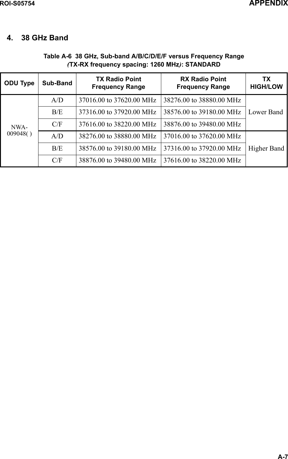
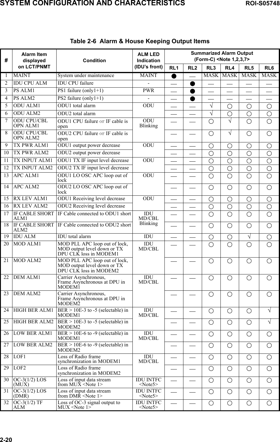
![Table 2-4 System Performance for 128QAM/ODUFrequency Band (GHz) 67-8 10-11 13 15 18 23 26 28 32 38 GuaranteedRange [GHz] 5.925-7.117.12-8.510.15-11.712.75-13.2514.25-15.3517.7-19.721.3-23.624.25-27.527.5-29.531.8-33.437.0-40.0−InterfacetypeDirect MountN/A N/A NEC Original −Remote mount *2N type or PDR 70N type or PDR 84PDR100PBR120PBR140PBR220PBR220PBR260PBR320PBR320PBR320−Output Power, nominal (dBm) (Measured at ODU output port)+25 +21 +21 +21 +19 +19 +18 +18 +17 +14.5 6-26G:±1.5 dB 28-38G:+1.5/−2.5 dBPower Control (1 dB step, variable)0 to 20 dB*3 0 to 20 dB*4 ±1.0 dBATPC range) 0 to 20 dB*4 0 to 20 dB*4 −Frequency Stability ± 6 ppm ±10 ppmThreshold Level (dBm), (Measured at ODU input port) at BER = 10-6 +3.0 dBChannel Separation (CS)= 28 (27.5)*1 MHz−69.5 −68.5 −68.5 −69 −69 −69 −68.5 −68.5 −67 −67BER = 10-3 Above value −1.5 dBSystem Gain (dB), (Measured at ODU input port) at BER = 10-6−3.0 dBChannel Separation = 28 (27.5)*1 MHz94.5 89.5 89.5 90 88 88 86.5 86.5 84 81.5BER = 10-3 Above value +1.5 dBMaximum Input Level −20 dBm for the BER less than 10-3−Residual BER Less than 10-12 at RSL=−30 dBm −SYSTEM CONFIGURATION AND CHARACTERISTICS ROI-S057482-18*1 27.5 MHz is applied for 18 GHz.*2 For the ODU of waveguide connection type, flange adapter is attached to the RF IN/OUT port in standard.*3 Additional attenuation (5 dB maximum) is available.*4 Additional attenuation is unavailable.Note: XPIC system has the same condition as above.](https://usermanual.wiki/NEC-of-America/58155.User-Manual-Part-1/User-Guide-1070882-Page-25.png)
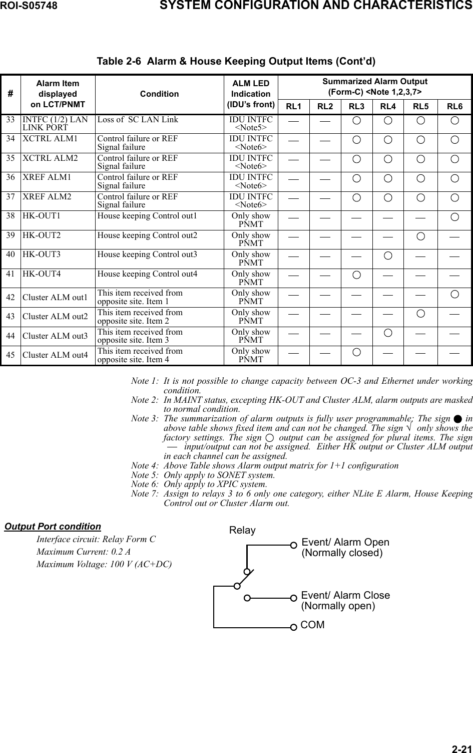
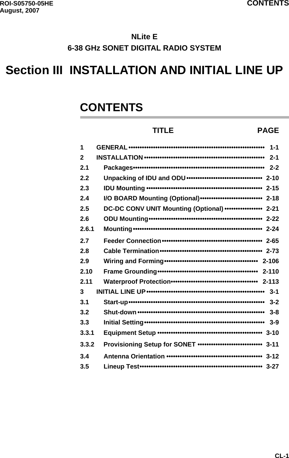
![SYSTEM CONFIGURATION AND CHARACTERISTICS ROI-S057482-242.4 Hybrid Combiner/DividerThere are two types of hybrid combiner/divider used in 1+1 protected systems, one is coaxial cable connection type for 6/7/8 GHz Bands and the other is ODU Direct Mount type for 11 - 38 GHz Bands. The following NEC Hybrid Combiner/Divider is suited for Andrew or RFS Antenna, and all NEC ODUs. 6/7/8 GHz Hybrid 11 - 52 GHz HybridFig. 2-6 HybridTable 2-9 CharacteristicsFrequencyBand[GHz]FrequencyRange[GHz]1-2 PORTVar ia ti o nMax.(dB)Loss Max. (dB)Isolation Min.(dB) VSWR Max. Interface (ANT Side) (ODU Side)L6 5.925 -6.425 0.5 3.7 20 1.3 UDR70 N ConnectorU6 6.43 -7.11 0.5 3.7 20 1.3 UDR70 N Connector77.125 -7.9 0.5 3.7 20 1.3 UDR84 N Connector87.7 -8.5 0.5 3.7 20 1.3 UDR84 N Connector11 10.5 -11.7 0.5 3.5 20 1.2NEC originalNEC original13 12.75 -13.25 0.5 3.5 20 1.215 14.5 -15.35 0.5 3.5 20 1.218 17.7 -19.7 0.5 3.5 20 1.223 21.2 -23.6 0.5 3.5 20 1.226 24.5 -26.5 0.5 3.8 20 1.232 31.8 -33.4 0.5 3.8 20 1.238 37 -39.5 0.5 3.8 20 1.2* Custom ordered for 28 GHz.](https://usermanual.wiki/NEC-of-America/58155.User-Manual-Part-1/User-Guide-1070882-Page-31.png)
![ROI-S05748 SYSTEM CONFIGURATION AND CHARACTERISTICS2-252.4.1 10 dB CouplerThere are two types of NEC 10 dB Coupler; one is coaxial cable connection type for 6/7/8 GHz bands and the other is ODU Direct Mount type for 11 - 38 GHz Bands. The following 10 dB Coupler is suited for Andrew or RFS Antenna, and all NEC ODUs. 6/7/8 GHz Coupler (N-Type) 11 - 38 GHz CouplerFig. 2-7 10 dB CouplerTable 2-10 CharacteristicsFrequency Band[GHz]Frequency Range [GHz]1-2 PORTVariation Max.(dB)Loss Max.(dB)Isolation Min.(dB) VSWR Max. Interface(ANT Side) (ODU Side)L6/U6 5.925 -7.125 0.5 1.2 20 1.3 UDR70 N Connector7/8 7.125 - 8.5 0.5 1.2 20 1.3 UDR84 N Connector11 10.5 - 11.7 0.5 1.2 20 1.2NEC original NEC original13 12.75 -13.25 0.5 1.2 20 1.215 14.5 -15.35 0.5 1.2 20 1.218 17.7 -19.7 0.5 1.2 20 1.223 21.2 -23.6 0.5 1.2 20 1.226 24.5 -26.5 0.5 1.2 20 1.232 31.8 - 33.4 0.5 1.2 20 1.238 37 -39.5 0.5 1.2 20 1.2* ODU for 6/7/8 GHz: Separate Type* ODU for 11 - 38 GHz: Direct Mount Type* Custom ordered for 28 GHz.](https://usermanual.wiki/NEC-of-America/58155.User-Manual-Part-1/User-Guide-1070882-Page-32.png)
![SYSTEM CONFIGURATION AND CHARACTERISTICS ROI-S057482-262.4.2 OMT (Ortho-Mode Transducer)The OMT enables dual polarization feature to double the transmission capacity for the NLite E system using the same frequency. The following NEC OMT has ODU Direct Mount type for 11-38 GHz Bands, which is suited for RFS Antenna and all NEC ODUs. Fig. 2-8 OMT TransducerTable 2-11 CharacteristicsFrequency Band[GHz]Frequency Range [GHz]XPD Min.[dB]LOSS Max.[dB] P-P ISOLATION Min.[dB]VSWR Max. INTERFACE WG INNER DIA. (mm)(ANT Side)INTERFACE (ODU Side)11 10.5 -11.7 35 0.6 38 1.3 18.0 NEC original13 12.75 -13.25 35 0.6 38 1.3 15.015 14.5 -15.35 35 0.6 38 1.3 13.5 18 17.7 -19.7 35 0.6 38 1.3 10.5 23 21.2 -23.6 35 0.6 38 1.3 9.0 26 24.5 -26.5 35 0.8 38 1.3 8.0 32 31.8 -33.4 35 1.0 38 1.3 6.538 37 -39.5 35 1.0 38 1.3 5.5](https://usermanual.wiki/NEC-of-America/58155.User-Manual-Part-1/User-Guide-1070882-Page-33.png)
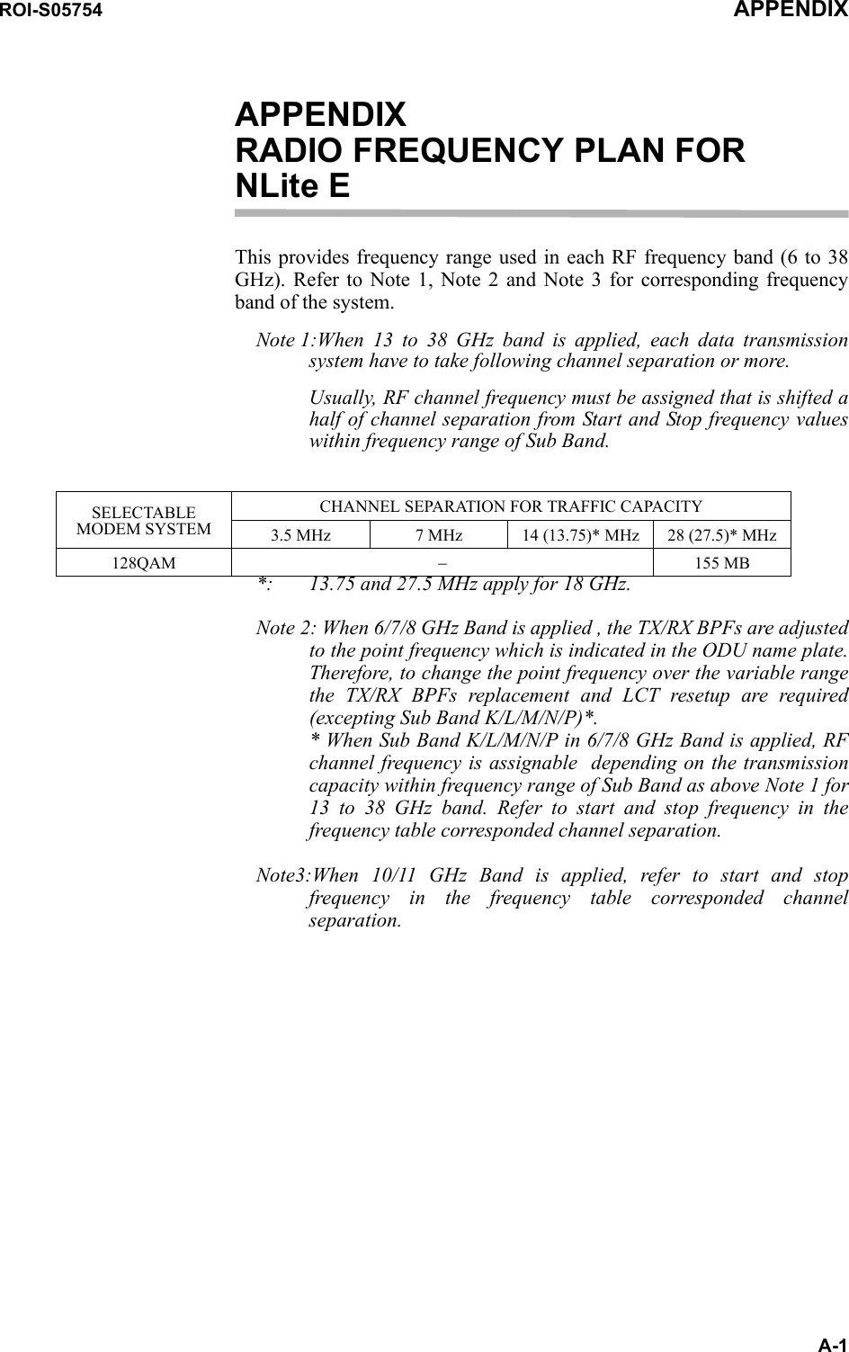
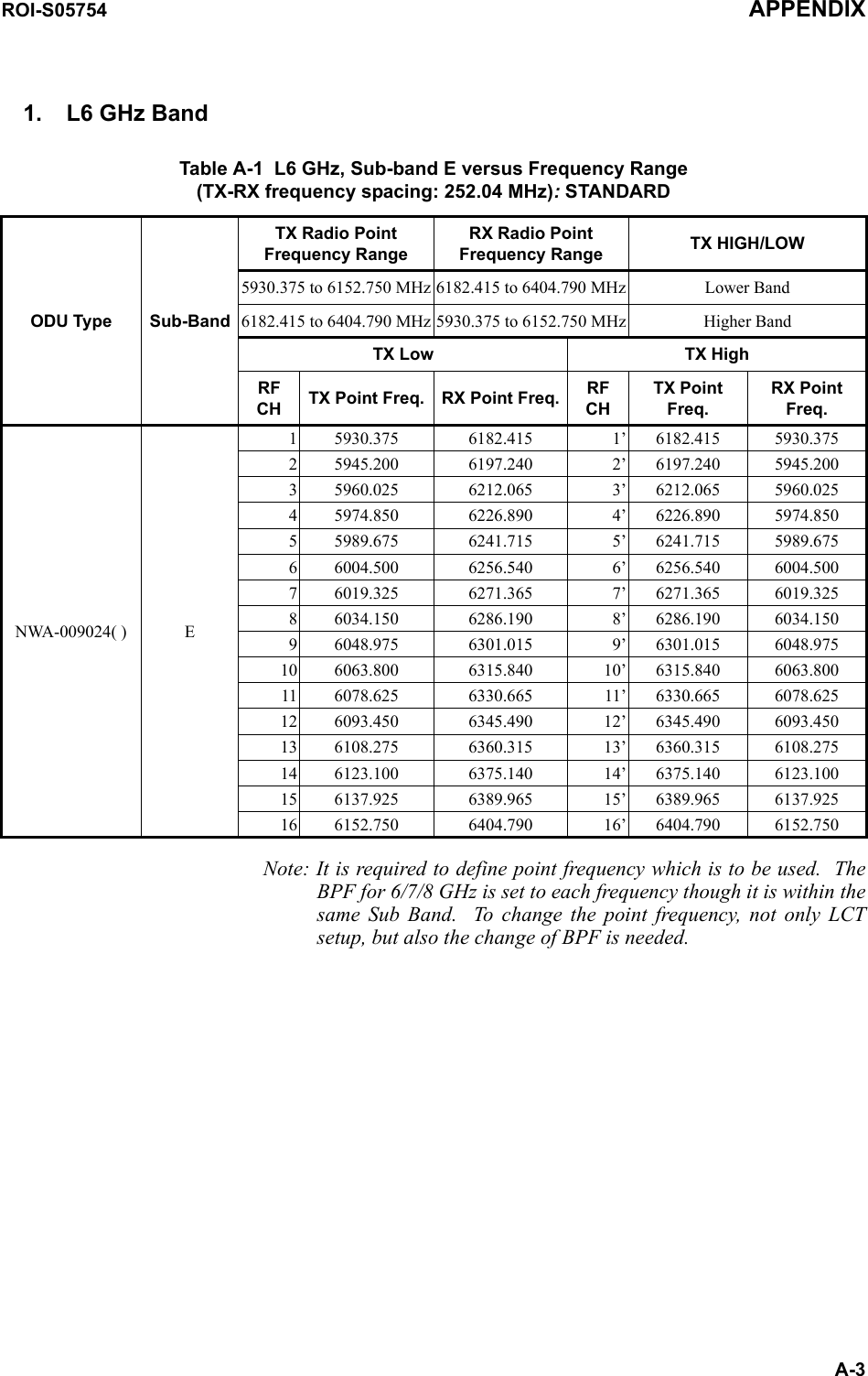
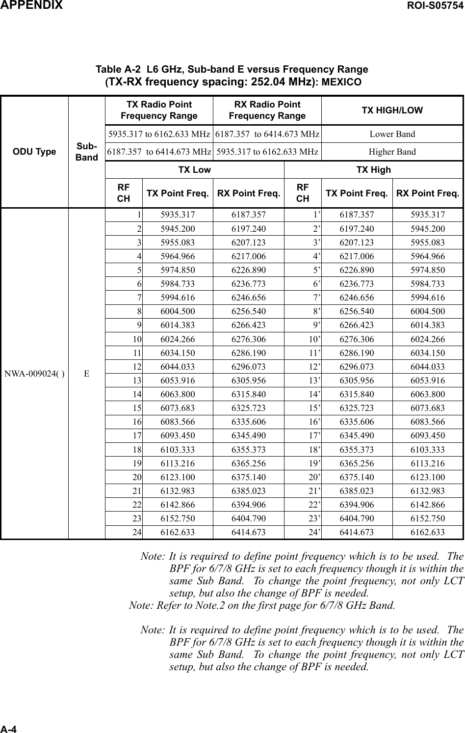
![ROI-S05748 SYSTEM CONFIGURATION AND CHARACTERISTICS2-272.5 RF Channel PlanRadio frequencies in 6 to 38 GHz applicable to NLite E are shown in the following Table: For details of frequency range in each Sub Band RF frequency band listed below, refer to the Appendix attached in this Section 1.Table 2-12 RF FrequenciesRF BAND [GHz] Tx-Rx Shift Frequency [MHz]L6 GHz :5.925 - 6.425 252.04/ 266U6 GHz :6.43 -7.11 3407 GHz :7.125 -7.9 154/ 161/ 196/ 2458 GHz :7.7 -8.5 119/ 126/ 151.614/ 154/ 266/ 294.44/ 305.56/ 310 311.3211 GHz :10.15 -11.7 49013 GHz :12.75 -13.25 26615 GHz :14.5 -15.35 315/ 420/ 470/ 490/ 644/ 72818 GHz :17.7 -19.7 340/ 156023 GHz :21.2 -23.6 120026 GHz :24.5 -26.5 855/ 1008/ 1123.528 GHz :27.5 -29.5 100832 GHz :31.8 -33.4 81238 GHz :37 -39.5 700/1000/ 1260/](https://usermanual.wiki/NEC-of-America/58155.User-Manual-Part-1/User-Guide-1070882-Page-34.png)