NEC of America 58155 NEC NLite E 155 MB 5.8 GHz Digital Microwave Radio User Manual Part 3
NEC Corporation of America NEC NLite E 155 MB 5.8 GHz Digital Microwave Radio Part 3
Contents
- 1. User Manual Part 1
- 2. User Manual Part 2
- 3. User Manual Part 3
- 4. User Manual Part 4
- 5. User Manual Part 5
User Manual Part 3
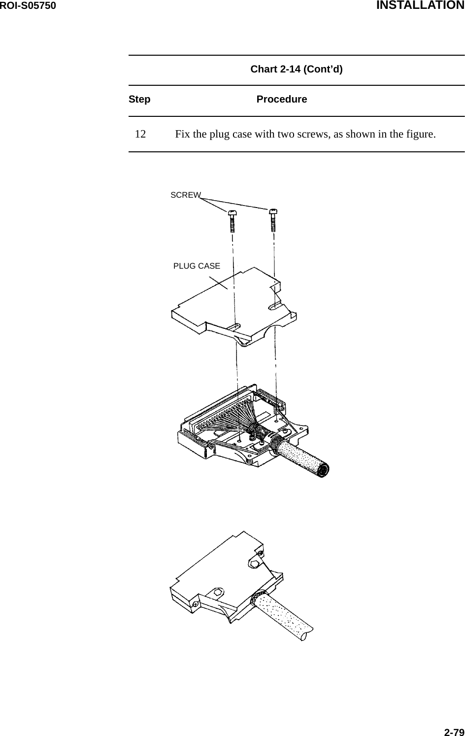
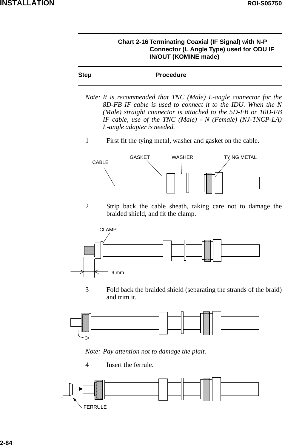
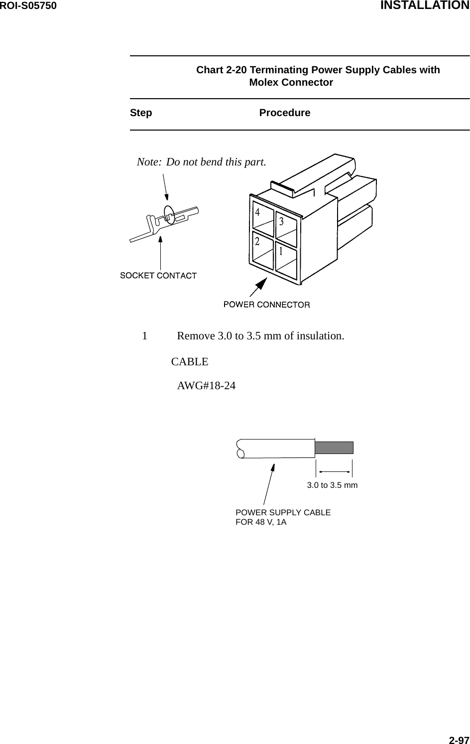
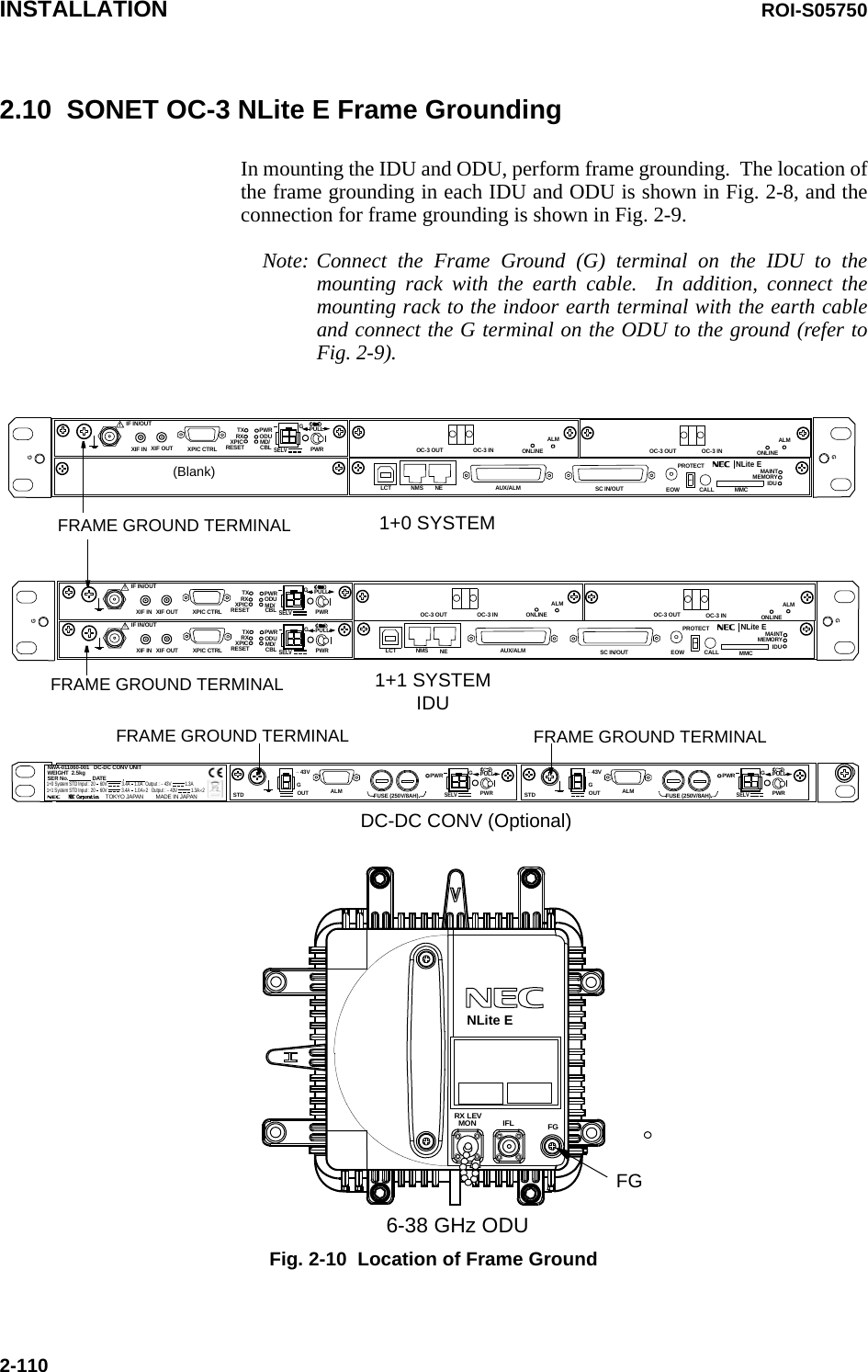
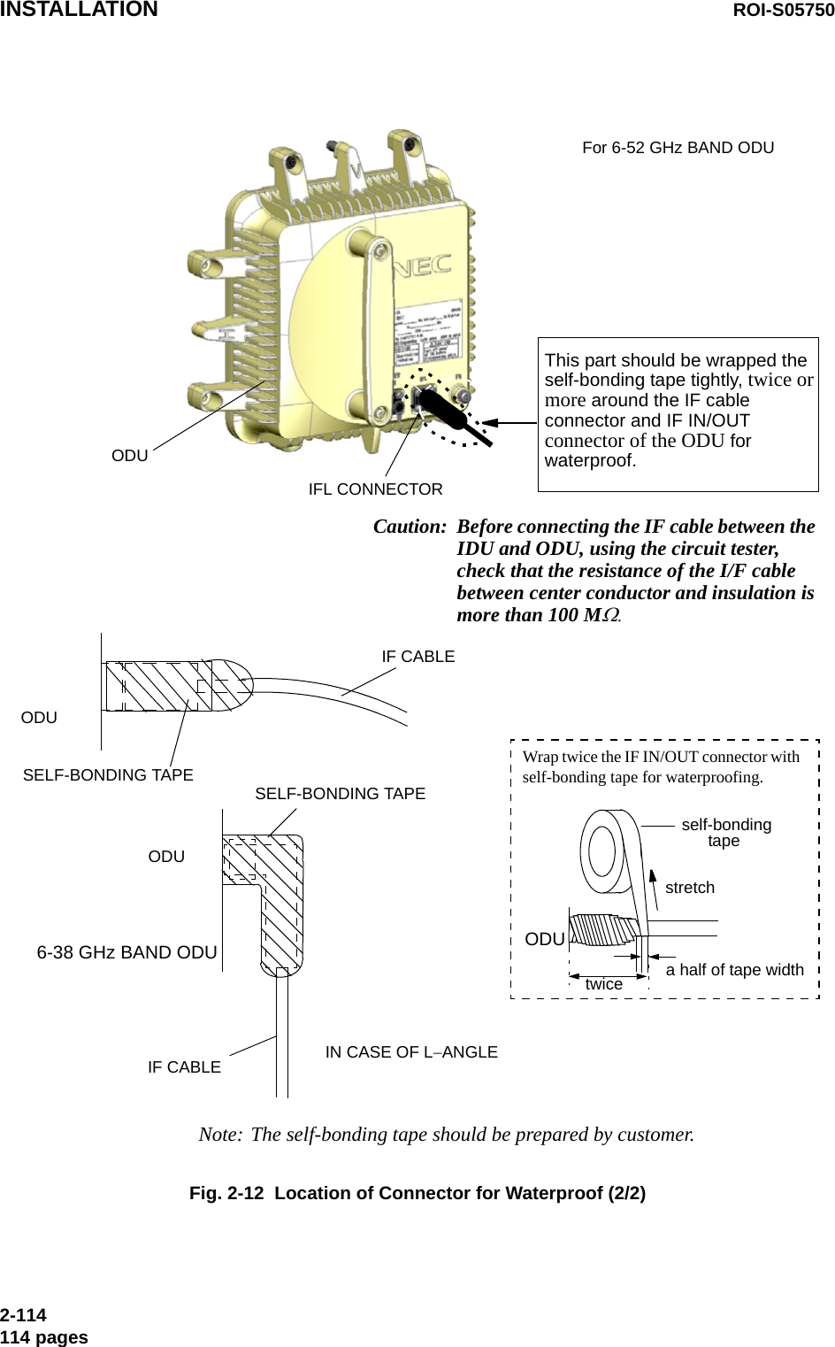
![INSTALLATION ROI-S057502-80Chart 2-15 Terminating IF Coaxial Cable with TNC-P Connector (L Angle Type) (HIROSE made) used for IDU IF IN/OUTStep ProcedureNote: It is recommended that TNC (Male) L-angle connector for the 8D-FB IF cable is used to connect it to the IDU. When the N (Male) straight connector is attached to the 5D-FB or 10D-FB IF cable, use of the TNC (Male) - N (Female) (NJ-TNCP-LA) L-angle adapter is needed.1 Pass the tightening nut, the washer and the gasket on the cable in the order shown in the figure. Then, strip the cable jacket in the diameter shown in the figure. [Applicable cable : 8D-FB-E]Note: Be careful of insertion direction for the gasket and the tightening nut.Note: Be careful not to damage the outer conductor.Note: Do not reuse the gasket because the clamp deforms it after tightening.2 Insert the clamp to clamp the stripped cable jacket end. Open the end of the outer conductor a little,3 Insert the hood between the plastic tape with aluminium foil and the outer conductor,ClampHoodNote: Use the insertion stick to open the hole of about φ9. No gap is allowed in between the clamp, the outer conductor and the hood.](https://usermanual.wiki/NEC-of-America/58155.User-Manual-Part-3/User-Guide-1070884-Page-4.png)
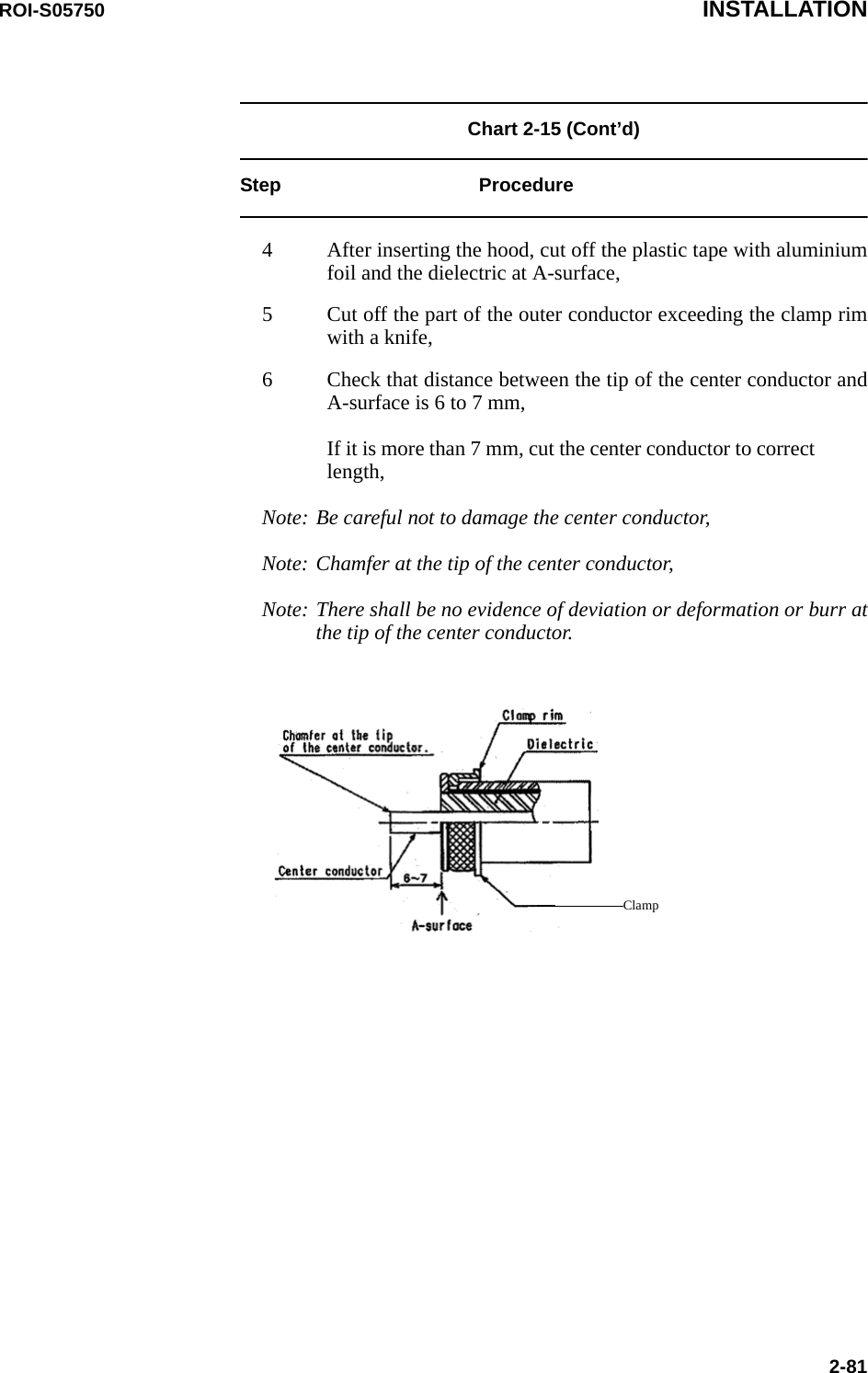
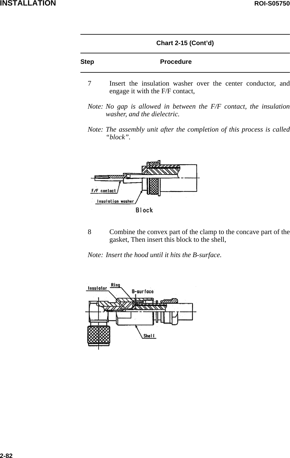
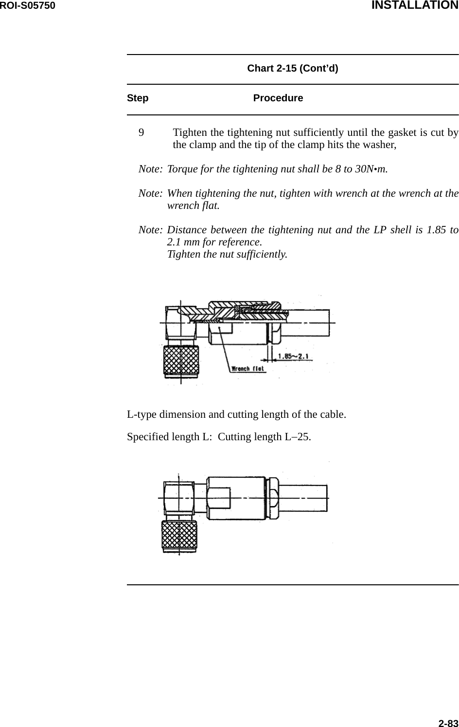
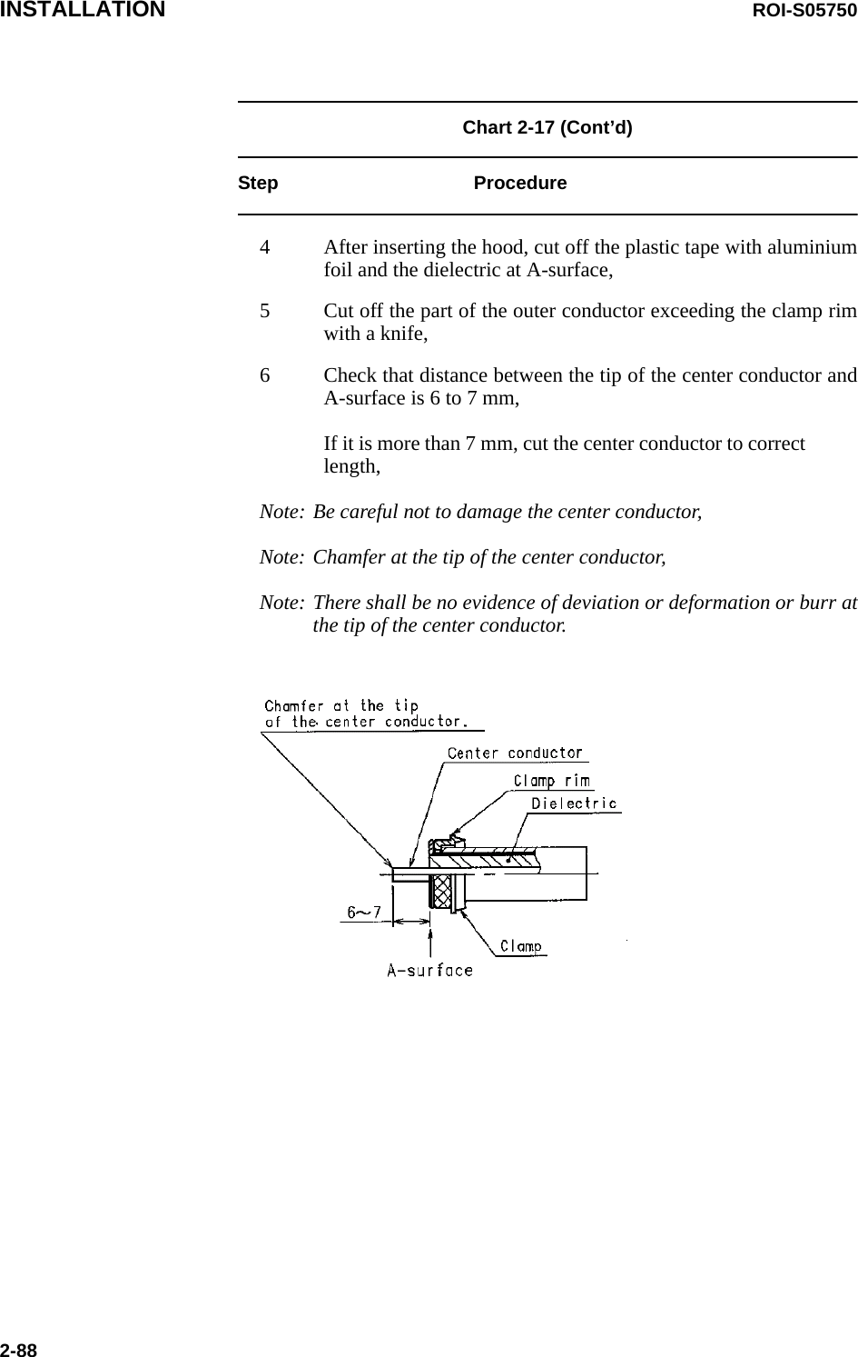
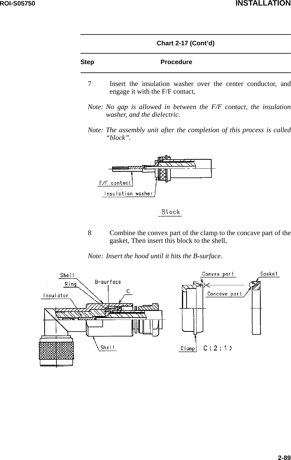
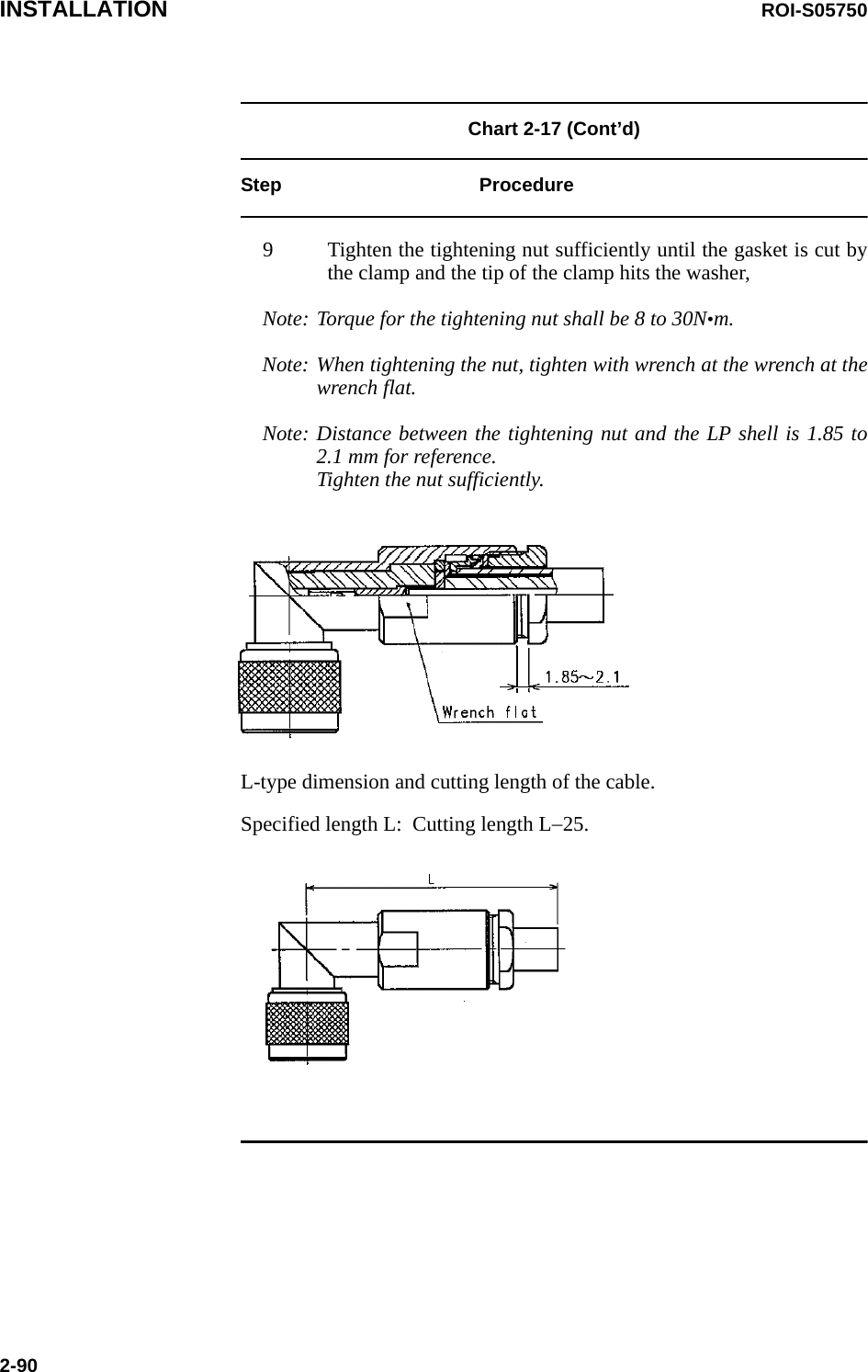
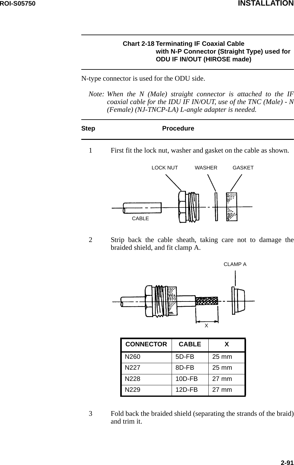
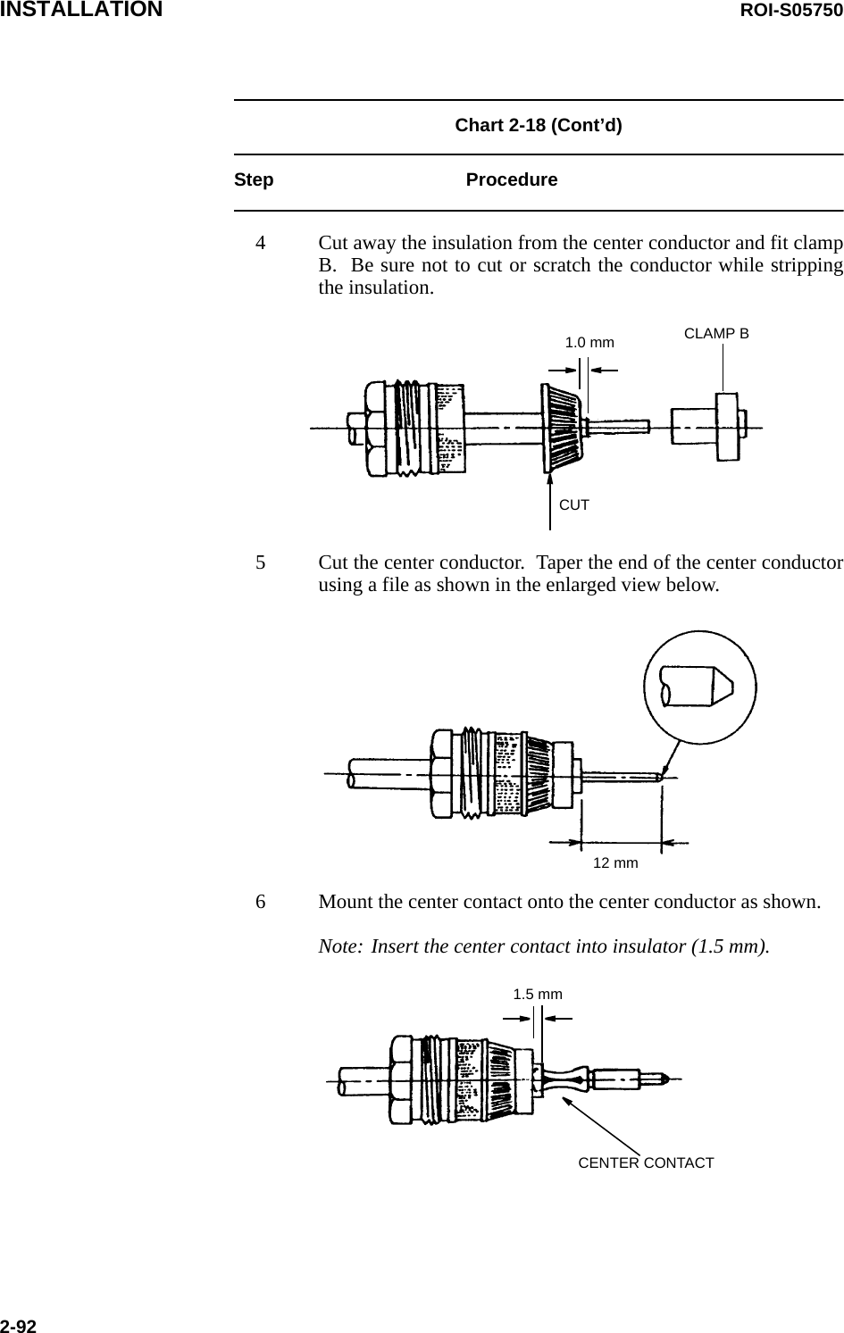
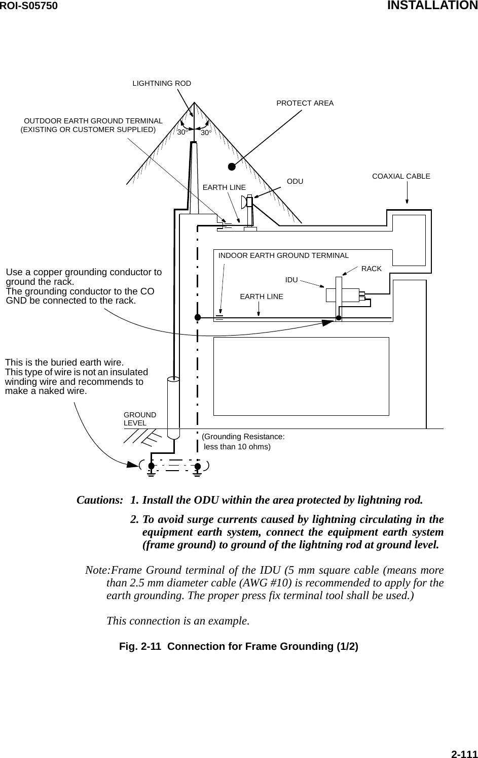
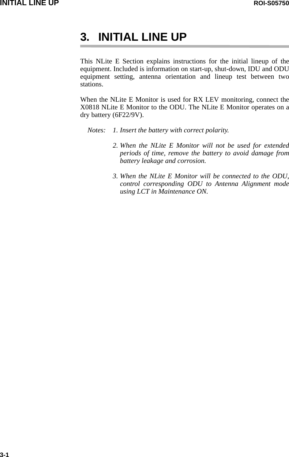
![ROI-S05750 INSTALLATION2-87Chart 2-17 Terminating IF Coaxial Cable with N-P Connector (L Angle Type) used for the ODU IF IN/OUT (HIROSE made)Step ProcedureNote: It is recommended that TNC (Male) L-angle connector for the 8D-FB IF cable is used to connect it to the IDU. When the N (Male) straight connector is attached to the 5D-FB or 10D-FB IF cable, use of the TNC (Male) - N (Female) (NJ-TNCP-LA) L-angle adapter is needed.1 Pass the tightening nut, the washer and the gasket on the cable in the order shown in the figure. Then, strip the cable jacket in the diameter shown in the figure. [Applicable cable : 8D-FB-E]Note: Be careful of insertion direction for the gasket and the tightening nut.Note: Be careful not to damage the outer conductor.Note: Do not reuse the gasket because the clamp deforms it after tightening.2 Insert the clamp to clamp the stripped cable jacket end. Open the end of the outer conductor a little,3 Insert the hood between the plastic tape with aluminium foil and the outer conductor,Note: Use the insertion stick to open the hole of about φ9. No gap is allowed in between the clamp, the outer conductor and the hood.](https://usermanual.wiki/NEC-of-America/58155.User-Manual-Part-3/User-Guide-1070884-Page-11.png)
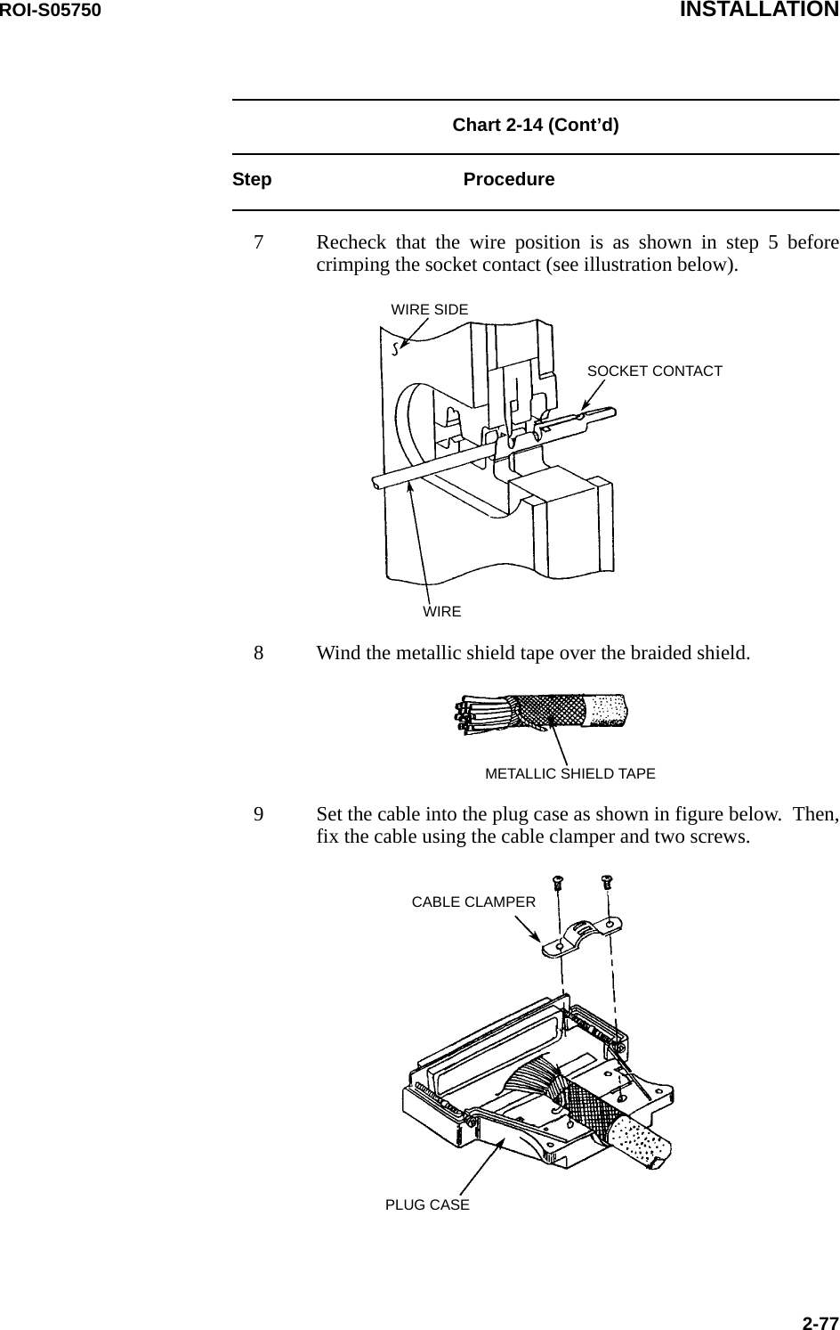
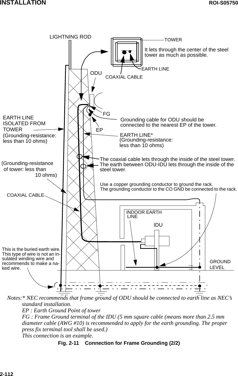
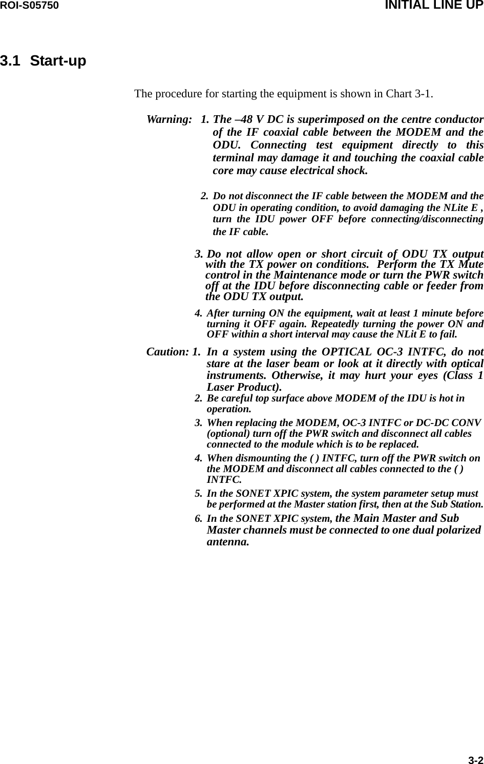
![ROI-S05750 INSTALLATION2-105Chart 2-23 (Cont’d) Step 8. After crimping the stranded wire to the contact using a hand tool, insert the contact into the contact chamber with the tool, working from the wiring side,Step 9. You can here the contacts snap home, audible “click”,Removing crimp contactsStep 1. Position the tool from the wiring side as shown left and insert into the contact chamber. The contact can then easily be removed from the wiring side together with itself and reinserted in a different chamber.Step 10.Check if they are securely in place with giving the wire a gentle pull.Insertion and removal tool(09 99 000 0513)WireConnectorInsertion and removal tool[Removal]Contact can be removedtogether with wire.[Insertion]Contact can be insertedtogether with wire.Contact chamberInsertion and removal toolPosition the](https://usermanual.wiki/NEC-of-America/58155.User-Manual-Part-3/User-Guide-1070884-Page-29.png)

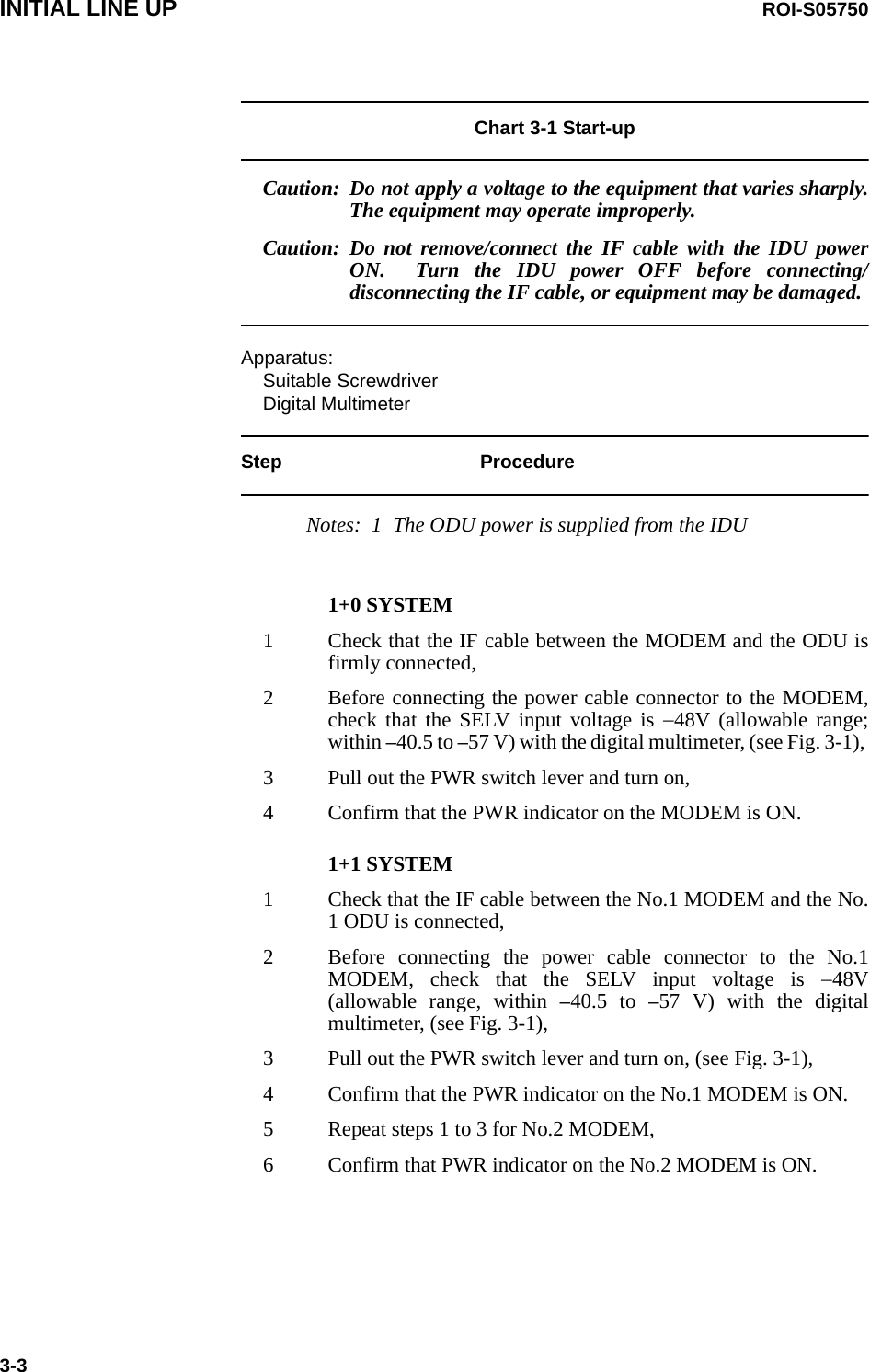
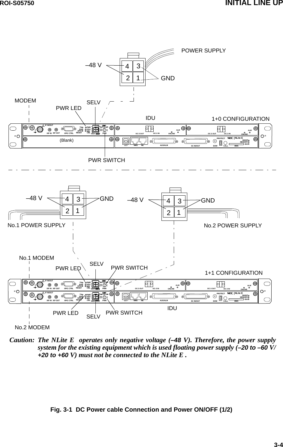
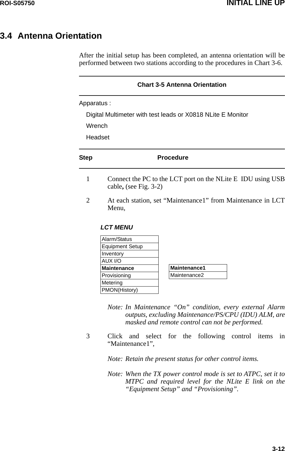
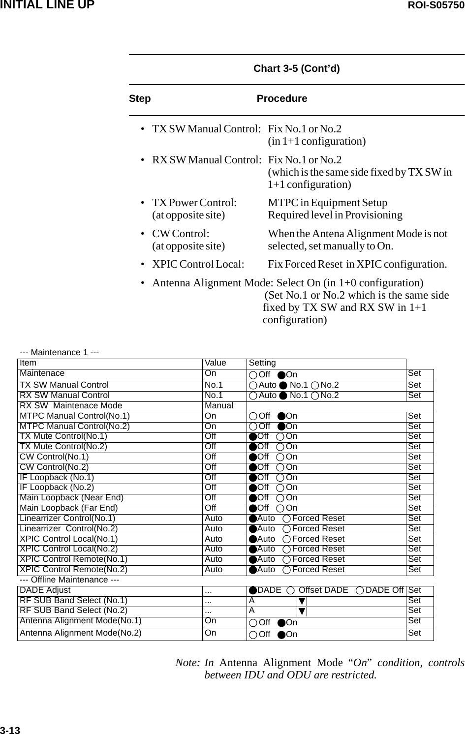
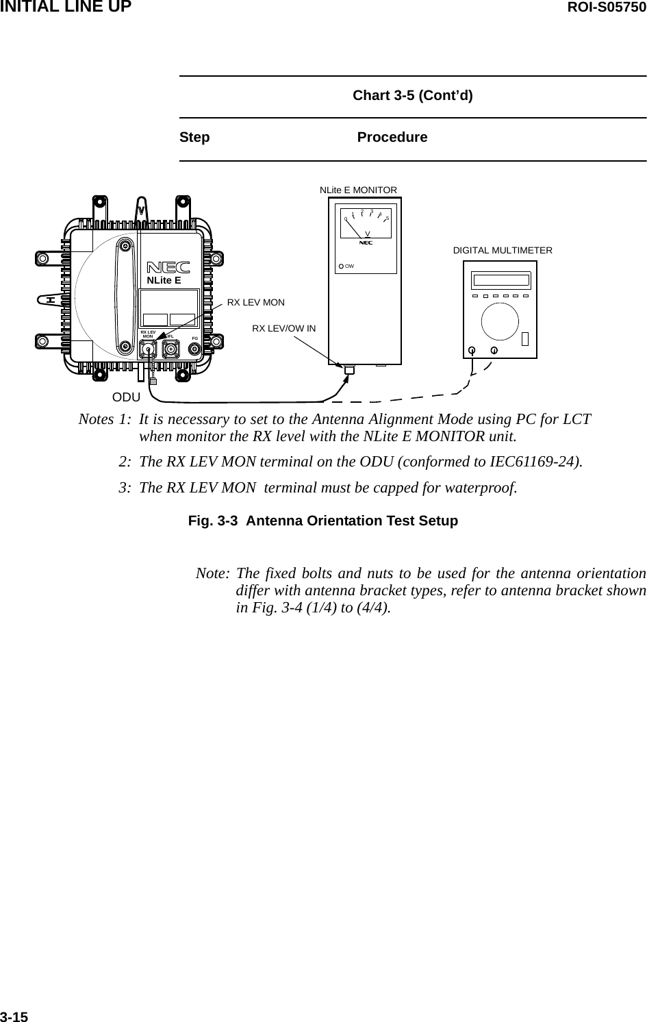
![ROI-S05750 INITIAL LINE UP3-14Chart 3-5 (Cont’d)Step Procedure4 At receiving station, remove a cap from the RX LEV MON jack, 5 At each station connect the digital multimeter or NLite E Monitor to the RX LEV MON jack on the ODU,Note: In order to measure exact performance of AGC V, it is mandatory required to set Antenna Alignment Mode to ON. The AGC voltage indication is not guaranteed outside Antenna Alignment Mode.It is necessary to set to Antenna Alignment Mode when monitor the RX level with the NLite E Monitor unit.6 At each station, adjust the azimuth and elevation angle of the antenna alternately so that the measured voltage becomes maximum,Note: The relation of the RX INPUT LEVEL versus RX LEVEL MON(V) is shown below. RX LEVEL MON vs RX INPUT LEVEL (Typical)RX INPUT LEVEL [dBm]-80 -70 -60 -50 -40 -30 -200.5011.522.533.544.5RX LEVEL MON [V]](https://usermanual.wiki/NEC-of-America/58155.User-Manual-Part-3/User-Guide-1070884-Page-53.png)