NEC of America 58155 NEC NLite E 155 MB 5.8 GHz Digital Microwave Radio User Manual Part 1
NEC Corporation of America NEC NLite E 155 MB 5.8 GHz Digital Microwave Radio Part 1
Contents
- 1. User Manual Part 1
- 2. User Manual Part 2
- 3. User Manual Part 3
- 4. User Manual Part 4
- 5. User Manual Part 5
User Manual Part 1

ROI-S05748-05DE CONTENTS
August, 2007
CL-1
NLite E
6-38 GHz SONET DIGITAL RADIO SYSTEM
Section I DESCRIPTION
CONTENTS
TITLE PAGE
1 GENERAL DESCRIPTION••••••••••••••••••••••••••••••••••••••••• 1-1
2 SYSTEM CONFIGURATION AND CHARACTERISTICS ••• 2-1
2.1 System Configuration •••••••••••••••••••••••••••••••••••••••••• 2-1
2.2 Performance Characteristics•••••••••••••••••••••••••••••••• 2-14
2.2.1 General System ••••••••••••••••••••••••••••••••••••••••••••••••• 2-14
2.2.2 LAN Interface (1000 Base-SX/1000 Base-T) (GbE)••••• 2-15
2.2.3 Service Channel (SC)•••••••••••••••••••••••••••••••••••••••••• 2-16
2.2.4 LCT (PNMT) Interface•••••••••••••••••••••••••••••••••••••••••• 2-16
2.2.5 PNMS Interface•••••••••••••••••••••••••••••••••••••••••••••••••• 2-16
2.2.6 RF I/O Port•••••••••••••••••••••••••••••••••••••••••••••••••••••••• 2-16
2.2.7 ODU (Outdoor Unit) and System performance ••••••••• 2-17
2.2.8 IDU (Indoor Unit) and System performance••••••••••••• 2-19
2.3 Interconnection between ODU and IDU •••••••••••••••••• 2-23
2.4 Hybrid Combiner/Divider ••••••••••••••••••••••••••••••••••••• 2-24
2.4.1 10 dB Coupler ••••••••••••••••••••••••••••••••••••••••••••••••••• 2-25
2.4.2 OMT (Ortho-Mode Transducer) ••••••••••••••••••••••••••••• 2-26
2.5 RF Channel Plan •••••••••••••••••••••••••••••••••••••••••••••••• 2-27
2.6 Power Supply•••••••••••••••••••••••••••••••••••••••••••••••••••• 2-28
CONTENTS ROI-S05748
CL-2
2 pages
(This page is intentionally left blank.)
ROI-S05748 CONTENTS
CL-3

ROI-S05748 GENERAL DESCRIPTION
1-1
1. GENERAL DESCRIPTION
This section provides descriptive information on the NLite E radios which
are used for the wide/narrow band point-to-point digital microwave radio
links.
The Indoor Unit (IDU) provides digital SDH (1 × STM-1) and/or LAN (2P
× 10/100BASE-T(X), 4P × 10/100BASE-T(X) or 1P × 1000BASE-SX/
1000BASE-T) signal transmission by the change of the data signal
interface card. It can select the modulation method 32QAM/128QAM, by
software selection depending on the transmission capacity that is
configured in the modulator/demodulator unit.
The Outdoor Unit (ODU) can be applied for a wide range of RF frequency
bands from 6/7/8/10/11/13/15/18/23/26/32/38 GHz.
Applications using the following redundancy configurations, Unprotected
(1+0), 2 × (1+0)*1, Protected (1+1), 2 × (1+1)*1 are available for NLite E
radio systems.
Notes: *1; XPIC
Cross Polarization Interference Canceller (XPIC) system is applied for
dual polarized systems using the same frequency in 2 × (1+0) and 2 ×
(1+1) configurations.

CONTENTS ROI-S0575
ATTENTION: TO REMAIN COMPLIANT WITH FCC PART
15 RULES INSTALLERS MUST UTILIZE SHIELDED CABLE
WHEN CONNECTING TO THE “XPIC CTRL” CONNECTOR.
ATTENTION: TO REMAIN COMPLIANT WITH FCC PART
15 RULES INSTALLERS MUST UTILIZE SHIELDED CABLE
WHEN CONNECTING TO THE “SC IN/OUT” CONNECTOR.
CL-2
2 pages
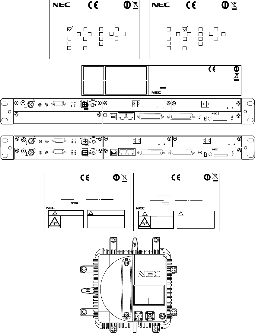
1+0 1+1 XPIC ETSI (RACK)
LABEL( EN FR ES DE IT)
NWM-001846-001
MADE IN JAPAN
0678
Nlite E
MDP-150MB-1AA INDOOR UNIT
INTFC(1) STM1-E STM1-0 LAN/WS GbE
16E1( ) 48E1 OTHER( )
INTFC(2) STM1-0 LAN/WS OTHER( )
TRP-( )G-1B
0678
NLite E
TRP-( )G-1B
OUTDOOR UNIT (NHG)
SHIFT FREQUENCY
MHz SUB BAND
(NWA-009034)
WEIGHT 3.5kg/ - 48V 0.5A
NEC Corporation TOKYO JAPAN MADE IN JAPAN
CAUTION
Non-ionizing
radiation
0678
-48V INPUT
Power down IDU before
disconnection or
connection of cable.
NLite E
TX
HIGH/LOW
WEIGHT 3.5kg/ - 48V 0.5A
NEC Corporation TOKYO JAPAN MADE IN JAPAN
CAUTION
Non-ionizing
radiation
-48V INPUT
Power down IDU before
disconnection or
connection of cable.
MHz
TX FREQUENCY
OUTDOOR UNIT (NHG)
SHIFT FREQUENCY
MHz SUB BAND TX
HIGH/LOW
SERIAL No. DATE SERIAL No. DATE
(NWA-009034)
PASOLINK NEO
FG
IFL
MON
RX LEV
IDU 1+1
ODU
1+0 1+1 XPIC ETSI (RACK)
LABEL( EN FR ES DE IT)
NWM-001846-001
MADE IN JAPAN
0678
NLite E
MDP-150MB-1AA INDOOR UNIT
INTFC(1) STM1-E STM1-0 LAN GbE
16E1( ) 48E1 OTHER( )
INTFC(2) STM1-0 LAN/WS OTHER( )
IDU 1+0
MDP-150MB-1AA
WEIGHT: 4 kg (WITH OPTION)
SER. No. DATE ,
INDOOR UNIT
−48 V 2.5A (WITH ODU & OPTION)
NEC Corporation
TOKYO JAPAN MADE IN JAPAN
(H2930)
0678
MODEM(1) INTFC (1) INTFC (2)
MODEM(2) CTRL
IDU Package Label
IDU Name Plate
ODU Name Plate
NLite E
SELV
!
AUX/ALM
NMS NE
ALM
SC IN/OUT EOW
PROTECT
CALL MMC
MAINT
MEMORY
IDU
XIF IN XIF OUT
IF IN/OUT TX
RX
RESET
XPIC CTRL XPIC
PWR
ODU
MD/
CBL PWR
NLite E NEO
LCT
OC-3 IN
OC-3 OUT
PULL
ALM
OC-3 IN
OC-3 OUT
(Blank)
ONLINE
ONLINE
G
G
G
SELV
!
AUX/ALM
NMS NE
ALM
SC IN/OUT EOW
PROTECT
CALL MMC
MAINT
MEMORY
IDU
XIF IN XIF OUT
IF IN/OUT TX
RX
RESET
XPIC CTRL XPIC
PWR
ODU
MD/
CBL PWR
NLite E NEO
LCT
OC-3 OUT OC-3 IN
PULL
SELV
!
XIF IN XIF OUT
IF IN/OUT TX
RX
RESET
XPIC CTRL XPIC
PWR
ODU
MD/
CBL PWR
PULL
ALM
OC-3 OUT OC-3 IN
ONLINE ONLINE
G
G
G
G
GENERAL DESCRIPTION ROI-S05748
1-2
2 pages

ROI-S05748 SYSTEM CONFIGURATION AND CHARACTERISTICS
2-1
2. SYSTEM CONFIGURATION AND
CHARACTERISTICS
This section provides outline of the system configuration, system
performance, RF channel plan, external alarm items and House keeping
input/output, and power supply.
2.1 System Configuration
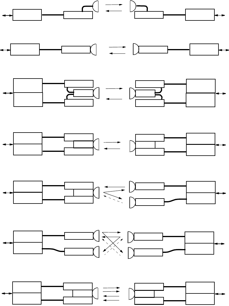
The system consists of the MDP-150MB-1AA Modulator-Demodulator
(Indoor Unit (IDU)) and TRP-(*1)G-1B Transmitter-Receiver (Outdoor
Unit (ODU)), Hybrid Combiner/Divider*2 or Orthogonal Mode Transducer
(OMT)*3 and the antenna.
The TRP-( )G-1B is available with frequency bands of 6 GHz to 38 GHz.
Notes: *1:ODU Type depends on the frequency band used, such as
TRP-(13)G-1B is applied for 13 GHz band.
*2:The Combiner/Divider is used in (1+1) single antenna
configuration for antenna direct mount type ODUs.
*3:The OMT is used in XPIC systems with antenna direct
mounting ODUs.
ODU
IDU
DATA
IN/OUT
1+0 IDU
IF Cable
ODU
IDU
DATA
IN/OUT
1+0 IDU
IF Cable
ODU (Working)
HYB
No.1
DATA
IN/OUT
ODU (Standby)
1+1 IDU
IF Cable
IF Cable
No.2
ODU IDU DATA
IN/OUT
1+0 IDU
IF Cable
ODU IDU DATA
IN/OUT
1+0 IDU
IF Cable
f1
f1’
ODU (Working)
HYB
No.1
DATA
IN/OUT
ODU (Standby)
1+1 IDU
IF Cable
IF Cable
No.2
f1
f1’
f1
f1’
ODU (Working)
HYB
No.1
DATA
IN/OUT
ODU (Standby)
1+1 IDU
IF Cable
IF Cable
No.2
ODU (Working) No.1
DATA
IN/OUT
ODU (Standby)
1+1 IDU
IF Cable
IF Cable No.2
f1’
ODU (Working)
HYB
No.1
DATA
IN/OUT
ODU (Standby)
1+1 IDU
IF Cable
IF Cable
f1
f1’
RF Cable
No.2
ODU (Working)
HYB
No.1
DATA
IN/OUT
ODU (Standby)
1+1 IDU
IF Cable
IF Cable
RF Cable
No.2
ODU (Working) No.1
DATA
IN/OUT
ODU (Standby)
1+1 IDU
IF Cable
IF Cable No.2
f1’
ODU (Working)
No.1
DATA
IN/OUT
ODU (Standby)
1+1 IDU
IF Cable
IF Cable
No.2
f1
f1
f1
ODU (Working)
HYB
No.1
DATA
IN/OUT
ODU (Working)
1+1 IDU
IF Cable
IF Cable
No.2
ODU (Working)
HYB
No.1
DATA
IN/OUT
ODU (Working)
1+1 IDU
IF Cable
IF Cable
No.2
f1
f1’
f2
f2’
RF Cable RF Cable
1+0 with Waveguide/Coaxial Cable Connection
1+0 with Antenna Direct Connection
1+1HS/HS with Coaxial Cable Connection
1+1 HS/HS with Antenna Direct Connection
1+1 HS/Hybrid SD with Antenna Direct Connection
1+1 HS SD with Antenna Direct Connection
1+1 Twin-path FD with Antenna Direct Connection
SYSTEM CONFIGURATION AND CHARACTERISTICS ROI-S05748
2-2
Fig. 2-1 Protected/Unprotected System Configuration (1/2)
ODU (Working) IDU DATA1
IN/OUT
ODU (Working)
IDU DATA2
IN/OUT
IDU
X IF Cable
1+0 IDU
IF Cable
IF Cable
1+0 IDU
V (H)
H (V)
H(V)
ODU (Working)
OMT
IDU DATA1
IN/OUT
ODU (Working)
IDU
DATA2
IN/OUT
IDU
X IF Cable
1+0 IDU
IF Cable
IF Cable
1+0 IDU
V (H)
H (V)
ODU (Working)
OMT
IDU
DATA1
IN/OUT
ODU (Working)
IDU
DATA2
IN/OUT
IDU
X IF Cable
1+0 IDU
IF Cable
IF Cable
1+0 IDU
V (H)
H (V)
ODU (Working)
HYB
No.1
DATA1
IN/OUT
ODU (Standby)
1+1 IDU
IF Cable
No.2
ODU (Working)
HYB
No.1
DATA2
IN/OUT
ODU (Standby)
1+1 IDU
IF Cable
No.2
IDU
X IF Cable IDU XPIC
CTRL
Cable
No. 1
No. 2
No. 1
No. 2
H (V)
V (H)
V (H)
H (V)
ODU (Working)
OMT
IDU DATA1
IN/OUT
ODU (Working)
IDU DATA2
IN/OUT
IDU
X IF Cable
1+0 IDU
IF Cable
IF Cable
1+0 IDU
V (H)
H (V)
ODU (Working)
OMT
IDU
DATA1
IN/OUT
ODU (Working)
IDU
DATA2
IN/OUT
IDU
X IF Cable
1+0 IDU
IF Cable
IF Cable
1+0 IDU
V (H)
H (V)
RF Cable
ODU (Working)
IDU
DATA1
IN/OUT
ODU (Working)
IDU
DATA2
IN/OUT
IDU
X IF Cable
1+0 IDU
IF Cable
IF Cable
1+0 IDU
V (H)
H (V)
RF Cable
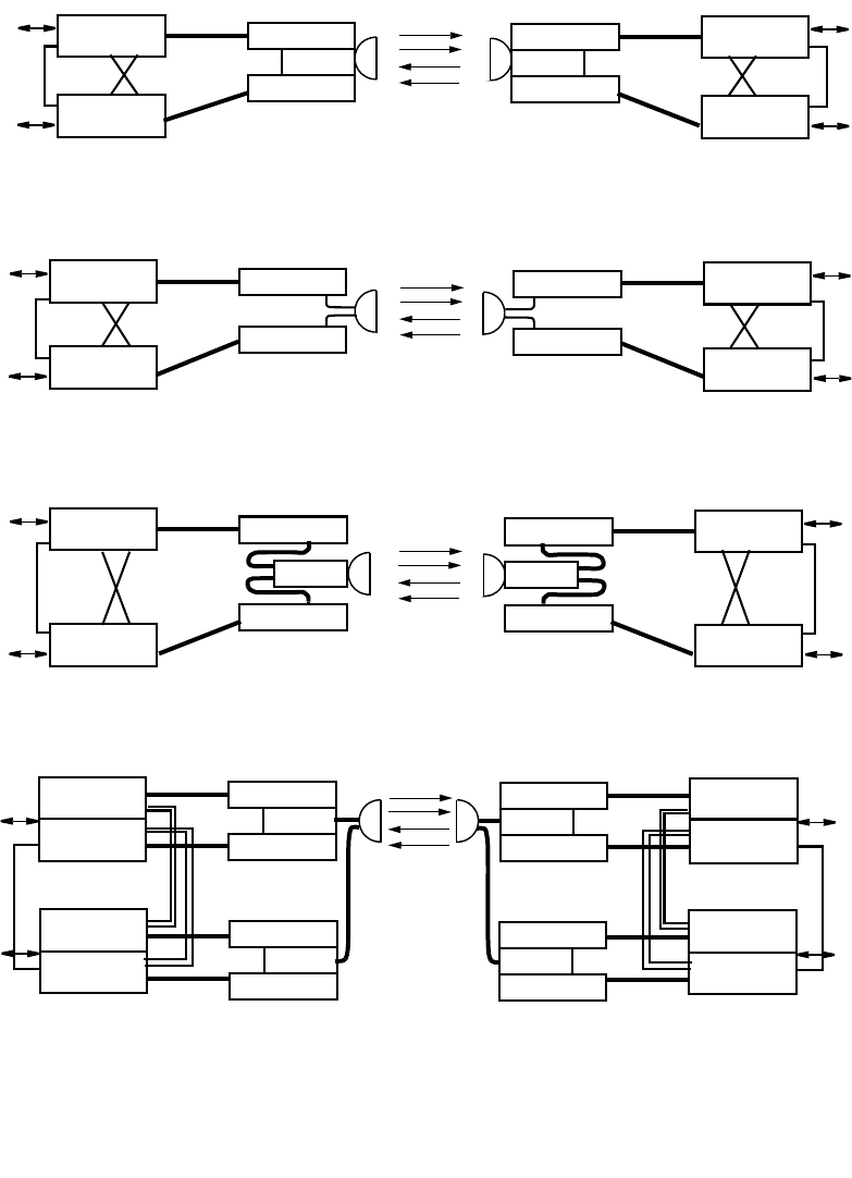
2(1+0) XPIC with Antenna Direct Connection
2(1+0) XPIC with Waveguide/Coaxial Cable Connection
2(1+0) XPIC with Waveguide/Coaxial Cable Connection
2(1+1) XPIC with Waveguide/Coaxial Cable Connection
ODU (Working)
HYB
No.1
DATA1
IN/OUT
ODU (Standby)
1+1 IDU
IF Cable
No.2
ODU (Working)
HYB
No.1
DATA2
IN/OUT
ODU (Standby)
1+1 IDU
IF Cable
No.2
IDU
X IF Cable
IDU XPIC
CTRL
Cable
No. 1
No. 2
No. 1
No. 2
H (V)
V (H)
V (H)
H (V)
IDU XPIC
CTRL
Cable
IDU XPIC
CTRL
Cable
IDU XPIC
CTRL
Cable
IDU XPIC
CTRL
Cable
IDU XPIC
CTRL
Cable
IDU XPIC
CTRL
Cable
f1
f1
f1’
f1’
f1
f1
f1’
f1’
f1
f1
f1’
f1’
f1
f1
f1’
f1’
ROI-S05748 SYSTEM CONFIGURATION AND CHARACTERISTICS
2-3
Fig. 2-1 Protected/Unprotected System Configuration (2/2)
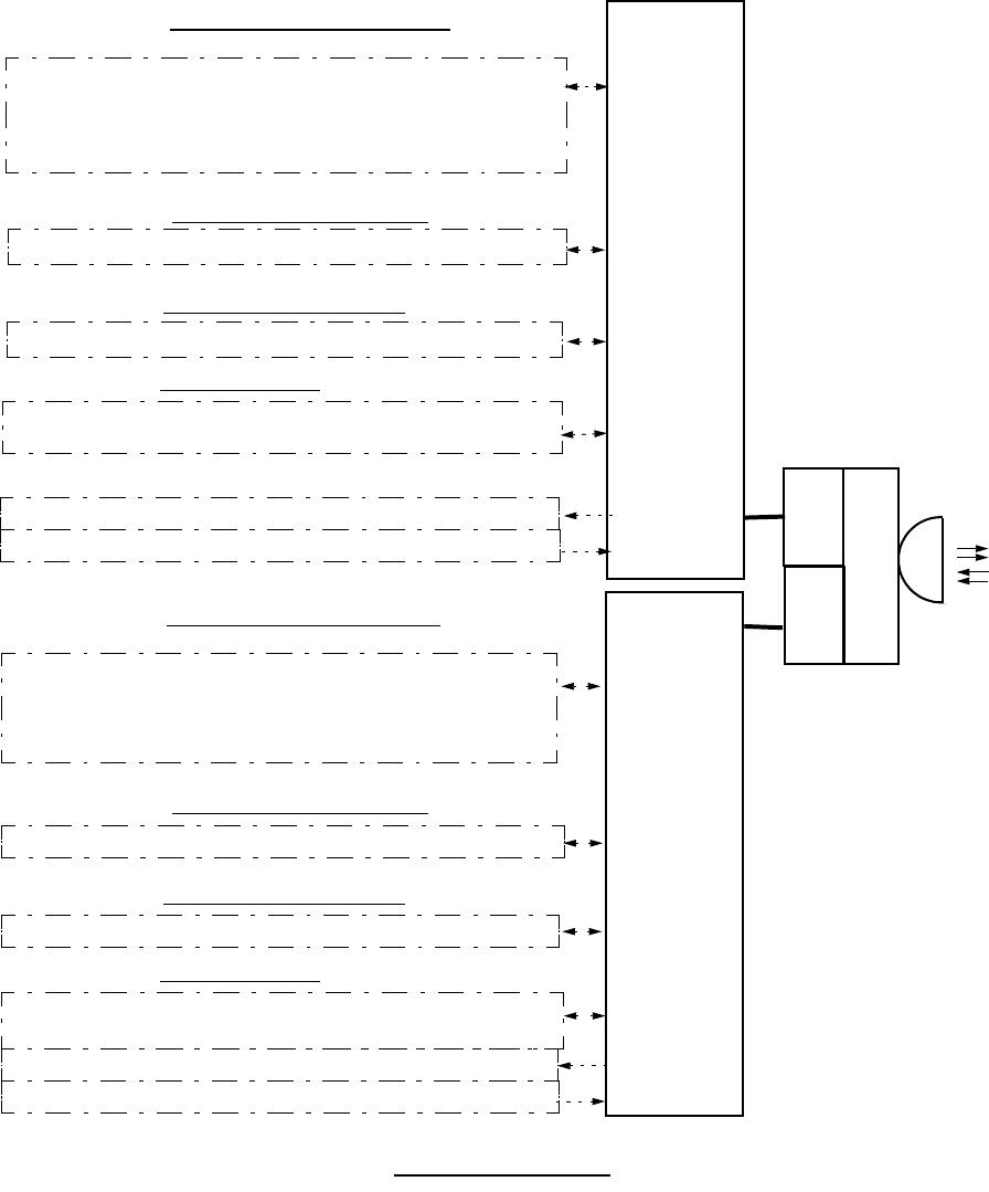
ODU
IDU
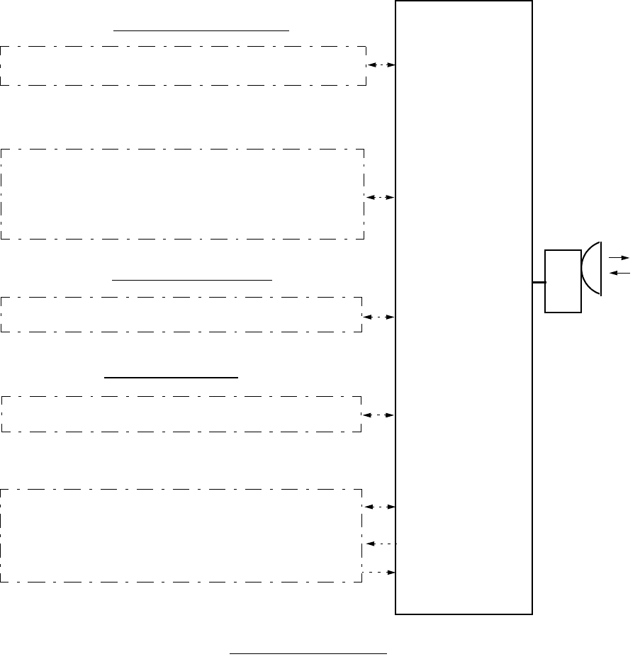
MAIN DATA INTFC (Selectable)
OC-3 (155 MB OPT) G.957, S-1.1/L-1.1
SC (2 × 64 KB V.11 + 2 × 9.6 KB RS-232C) +
EOW (1)
1000 Base T/SX IEEE 802.3z 6 to 38 GHz
128QAM
32/128QAM
ALM/HK/SC (AUX) INTFC
6 ALM OUT (4 HK OUT/4 Cluster OUT) 32/128QAM
6 HK IN/4 Cluster IN 32/128QAM
10/100 Base T(X) 2-Port LAN IEEE802.3
2 MB + 64/128/192/256 KB SC- LAN 128QAM
LAN INTFC (Additional)
OC-3 (155 MB OPT) ITU-T G.957, S-1.1/L-1.1 128QAM
MAIN DATA INTFC (for APS)
1+0/1+1 Configuration
32QAM
10/100 Base T(X) 4-Port LAN (100 MB) IEEE802.3 +
SYSTEM CONFIGURATION AND CHARACTERISTICS ROI-S05748
2-4
Fig. 2-2 Signal Interface/Capacity (1/2)
ODU
ODU
6 to 38 GH
z
OMT
OC-3 (155 MB OPT) G.957, S-1.1/L-1.1
SC (2 × 64 KB V.11 + 2 × 9.6 KB RS-232C) +
EOW (1 )
1000 Base T/SX IEEE 802.3z
128QAM
ALM/HK/SC(AUX)
6 ALM OUT (4 HK OUT/4 Cluster OUT)
6 HK IN/4 Cluster IN
10/100 Base T(X) 2-Port LAN IEEE 802.3
2 MB + 64/128/192/256 KB SC- LAN
SC-LAN INTFC (Additional)
OC-3 (155 MB OPT) G.957, S-1.1/L-1.1
MAIN DATA INTFC (for APS)
MAIN DATA INTFC (Selectable)
OC-3 (155 MB OPT) G.957, S-1.1/L-1.1
SC (2 × 64 KB V.11 + 2 × 64 KB RS-232C) +
EOW (1)
1000 Base T/SX IEEE 802.3z
128QAM
ALM/HK/SC(AUX)
6 ALM OUT (4 HK OUT/4 Cluster OUT)
6 HK IN/4 Cluster IN
10/100 Base T(X) 2-Port LAN
2 MB + 64/128/192/256 KB SC- LAN
SC-LAN INTFC (Additional)
OC-3 (155 MB OPT) G.957, S-1.1/L-1.1
MAIN DATA INTFC (for APS)
MAIN DATA INTFC (Selectable)
No.2
No.1
IDU
IDU
XPIC Configuration
ROI-S05748 SYSTEM CONFIGURATION AND CHARACTERISTICS
2-5
Fig. 2-2 Signal Interface/Capacity (2/2)
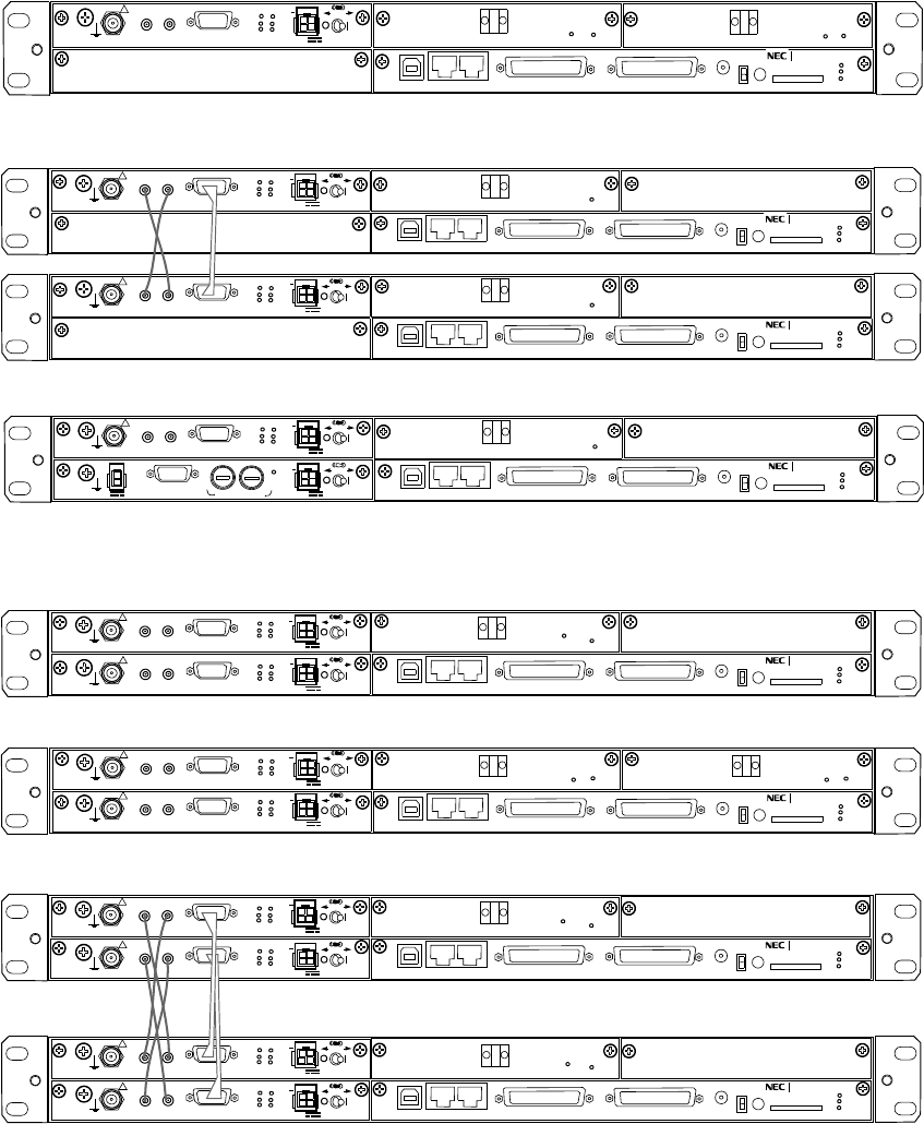
Unprotected Systems (IDU)
SELV
!
AUX/ALM
NMS NE
ALM
SC IN/OUT EOW
PROTECT
CALL MMC
MAINT
MEMORY
IDU
XIF IN XIF OUT
IF IN/OUT
TX
RX
RESET
XPIC CTRL
XPIC
PWR
ODU
MD/
CBL PWR
NLite E NEO
LCT
OC-3 IN
OC-3 OUT
PULL
Equipped with OC-3 Optical Interface for APS
SELV
!
AUX/ALM
NMS NE
ALM
SC IN/OUT EOW
PROTECT
CALL MMC
MAINT
MEMORY
IDU
XIF IN XIF OUT
IF IN/OUT
TX
RX
RESET
XPIC CTRL
XPIC
PWR
ODU
MD/
CBL
PULL
PWR
NLite E NEO
LCT
Equipped with OC-3 Optical Interface in XPIC
SELV
!
AUX/ALM
NMS NE
ALM
SC IN/OUT EOW
PROTECT
CALL MMC
MAINT
MEMORY
IDU
XIF IN XIF OUT
IF IN/OUT
TX
RX
RESET
XPIC CTRL
XPIC
PWR
ODU
MD/
CBL
PULL
PWR
NLite E NEO
LCT
ALM
OC-3 IN
OC-3 OUT
(Blank)
(Blank)
(Blank)
(Blank)
SELV
!
AUX/ALM
NMS NE SC IN/OUT EOW
PROTECT
CALL MMC
MAINT
MEMORY
IDU
XIF IN XIF OUT
IF IN/OUT
TX
RX
RESET
XPIC CTRL
XPIC
PWR
ODU
MD/
CBL
PULL
PWR
NLite E NEO
LCT
Equipped with DC-DC CONV
SELV
PWR PULL
PWR
ALM FUSE (250V/8AH)
−
43V
G
OUT
ONLINE
ONLINE
(Blank)
G
G
G
G
G
G
G
G
STD
G
G
G
G
G
ALM
(Blank)
SELV
!
AUX/ALM
NMS NE
ALM
SC IN/OUT EOW
PROTECT
CALL MMC
MAINT
MEMORY
IDU
XIF IN XIF OUT
IF IN/OUT
TX
RX
RESET
XPIC CTRL
XPIC
PWR
ODU
MD/
CBL
PULL
PWR
NLite E NEO
LCT
SELV
!
AUX/ALM
NMS NE
ALM
SC IN/OUT EOW
PROTECT
CALL MMC
MAINT
MEMORY
IDU
XIF IN XIF OUT
IF IN/OUT
TX
RX
RESET
XPIC CTRL
XPIC
PWR
ODU
MD/
CBL PWR
NLite E NEO
LCT
OC-3 OUT OC-3 IN
PULL
Equipped with OC-3 Optical Interface
Equipped with OC-3 Optical Interface in APS
SELV
!
XIF IN XIF OUT
IF IN/OUT
TX
RX
RESET
XPIC CTRL
XPIC
PWR
ODU
MD/
CBL PWR
PULL
SELV
!
XIF IN XIF OUT
IF IN/OUT
TX
RX
RESET
XPIC CTRL
XPIC
PWR
ODU
MD/
CBL PWR
PULL
ALM
OC-3 OUT OC-3 IN
(Blank)
ONLINE ONLINE
G
G
G
G
G
G
G
G
Protected Systems (IDU)
SELV
!
AUX/ALM
NMS NE
ALM
SC IN/OUT EOW
PROTECT
CALL MMC
MAINT
MEMORY
IDU
XIF IN XIF OUT
IF IN/OUT
TX
RX
RESET
XPIC CTRL
XPIC
PWR
ODU
MD/
CBL
PULL
PWR
NLite E NEO
LCT
Equipped with OC-3 Optical Interface in XPIC
SELV
!
XIF IN XIF OUT
IF IN/OUT
TX
RX
RESET
XPIC CTRL
XPIC
PWR
ODU
MD/
CBL PWR
PULL
SELV
!
AUX/ALM
NMS NE
ALM
SC IN/OUT EOW
PROTECT
CALL MMC
MAINT
MEMORY
IDU
XIF IN XIF OUT
IF IN/OUT
TX
RX
RESET
XPIC CTRL
XPIC
PWR
ODU
MD/
CBL
PULL
PWR
NLite E NEO
LCT
SELV
!
XIF IN XIF OUT
IF IN/OUT
TX
RX
RESET
XPIC CTRL
XPIC
PWR
ODU
MD/
CBL PWR
PULL
(Blank)
(Blank)
G
G
G
G
G
G
G
G
OC-3 OUT OC-3 IN ONLINE
ONLINE
ONLINE
OC-3 OUT OC-3 IN
OC-3 OUT OC-3 IN
OC-3 IN
OC-3 OUT
OC-3 IN
OC-3 OUT
OC-3 IN
OC-3 OUT
SYSTEM CONFIGURATION AND CHARACTERISTICS ROI-S05748
2-6
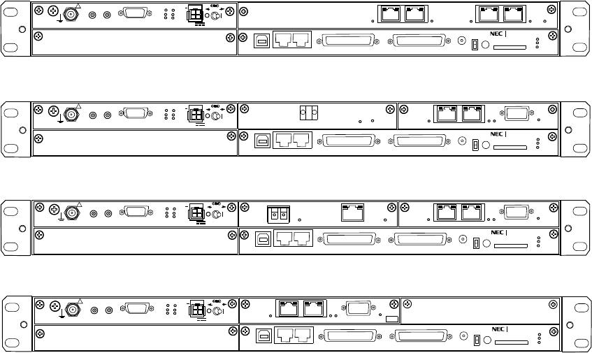
Fig. 2-3 IDU e/w Standard and Optional Interface (1/2)
SELV
!
AUX/ALM
NMS NE SC IN/OUT EOW
PROTECT
CALL MMC
MAINT
MEMORY
IDU
XIF IN XIF OUT
IF IN/OUT
TX
RX
RESET
XPIC CTRL
XPIC
PWR
ODU
MD/
CBL
PULL
PWR
NLite E NEO
LCT
SELV
!
AUX/ALM
NMS NE SC IN/OUT EOW
PROTECT
CALL MMC
MAINT
MEMORY
IDU
XIF IN XIF OUT
IF IN/OUT
TX
RX
RESET
XPIC CTRL
XPIC
PWR
ODU
MD/
CBL PWR
NLite E NEO
LCT
PULL
Equipped with GbE Interface with SC LAN Interface (SONET) 153 MB
G
G
G
G
G
G
ALM
WS IN/OUT
100M PORT 1 PORT 2 100M
WS
ALM
OC-3 OUT OC-3 IN ONLINE
ALM
WS IN/OUT
100M PORT 1 PORT 2 100M
WS
ALM
OUT
1000BASE-SX
PORT
IN
(Blank)
(Blank)
SELV
!
AUX/ALM
NMS NE SC IN/OUT EOW
PROTECT
CALL MMC
MAINT
MEMORY
IDU
XIF IN XIF OUT
IF IN/OUT
TX
RX
RESET
XPIC CTRL
XPIC
PWR
ODU
MD/
CBL PWR
NLite E NEO
ALM
LCT
PULL
Equipped with 4P LAN Interface 32 QAM 100MB
(Blank)
G
G
G
100M PORT 3 PORT4 100M
100M PORT 1 PORT 2 100M
SELV
!
AUX/ALM
NMS NE SC IN/OUT EOW
PROTECT
CALL MMC
MAINT
MEMORY
IDU
XIF IN XIF OUT
IF IN/OUT
TX
RX
RESET
XPIC CTRL
XPIC
PWR
ODU
MD/
CBL
PULL
PWR
NLite E NEO
LCT
Equipped with LAN Interface for Main LAN (SONET) 2 x FE
G
G
ALM
WS IN/OUT
100M PORT 1 PORT 2 100M
WS
(Blank)
M S
.
G
Equipped with OC-3 Optical Interface with SC LAN Interface (SONET) 155MB
ROI-S05748 SYSTEM CONFIGURATION AND CHARACTERISTICS
2-7
Fig. 2-3 IDU e/w Standard and Optional Interface (2/2)
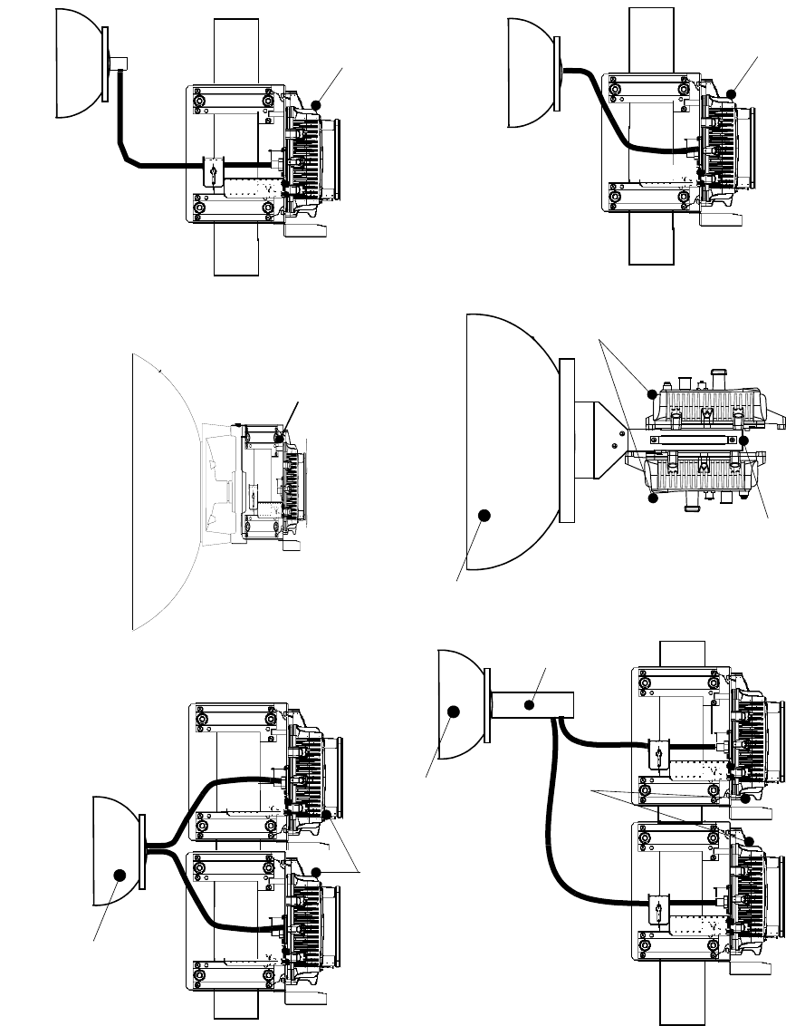
Antenna
Waveguide Connection (1+0)
ODU
Antenna Direct Mounting 2(1+0)
ODU
OMT
Coaxial Cable Connection 6/7/8GHz 2(1+0)
ODU
OMT
Coaxial Cable Connection 6/7/8GHz (1+0)
ODU
Waveguide Connection 2(1+0)
ODU
Dual Pol. Antenna
Dual Pol. Antenna
Dual Pol. Antenna
ODU
Antenna Direct Mounting (1+0)
SYSTEM CONFIGURATION AND CHARACTERISTICS ROI-S05748
2-8
Fig. 2-4 Configuration of the ODU (1/3)
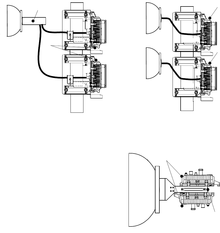
Waveguide Connection (1+1 SD)
ODU
ODU
Antenna Direct Mounting (1+1)
ODU
HYB
Coaxial Cable Connection 6/7/8 GHz (1+1)
ODU
HYB
ROI-S05748 SYSTEM CONFIGURATION AND CHARACTERISTICS
2-9
Fig. 2-4 Configuration of the ODU (2/3)
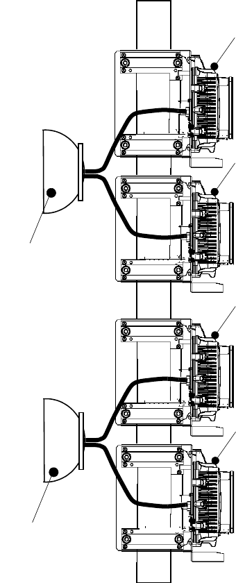
Waveguide Connection 2(1+1) XPIC
ODU
ODU
ODU
ODU
Dual Pol. Antenna
Dual Pol. Antenna
(REG)
(PROT)
SYSTEM CONFIGURATION AND CHARACTERISTICS ROI-S05748
2-10
Fig. 2-4 Configuration of the ODU (3/3)
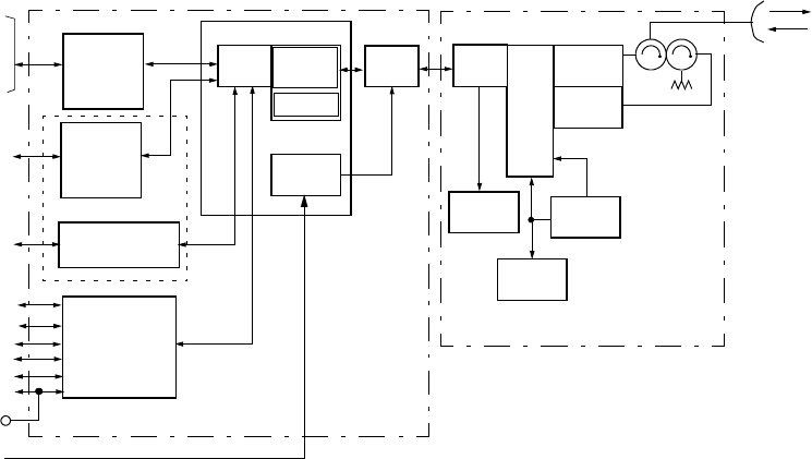
Fig. 2-5 System Block Diagram (1/3)
IN/OUT
( )INTFC *1
CTRL
NMS
LCT
EOW
MODEM
DC-DC
CONV
LAN/WS INTFC *3
SC-LAN
RF
PS
CKT
SYNTH
(LO)
CTRL
IDU ODU
ALM IN/OUT
OC-3 (OPT)/
BPF
(TX)
BPF
(RX)
ODU
INTFC
ODU
INTFC
DPU/
FEC
SC IN/OUT
NE
128QAM
MODEM
OC-3 (OPT)
1+0 CONFIGURATION FOR SONET
2-PORT LAN
fH(L)
fL(H)
6 to 38 GHz
GbE
EOW
(JACK)
LPF/EQL
PS IN
Notes: *1 :Optional
*2:Provides for APS
*3:Provides for auxiliary signals
( )INTFC *2
ROI-S05748 SYSTEM CONFIGURATION AND CHARACTERISTICS
2-11
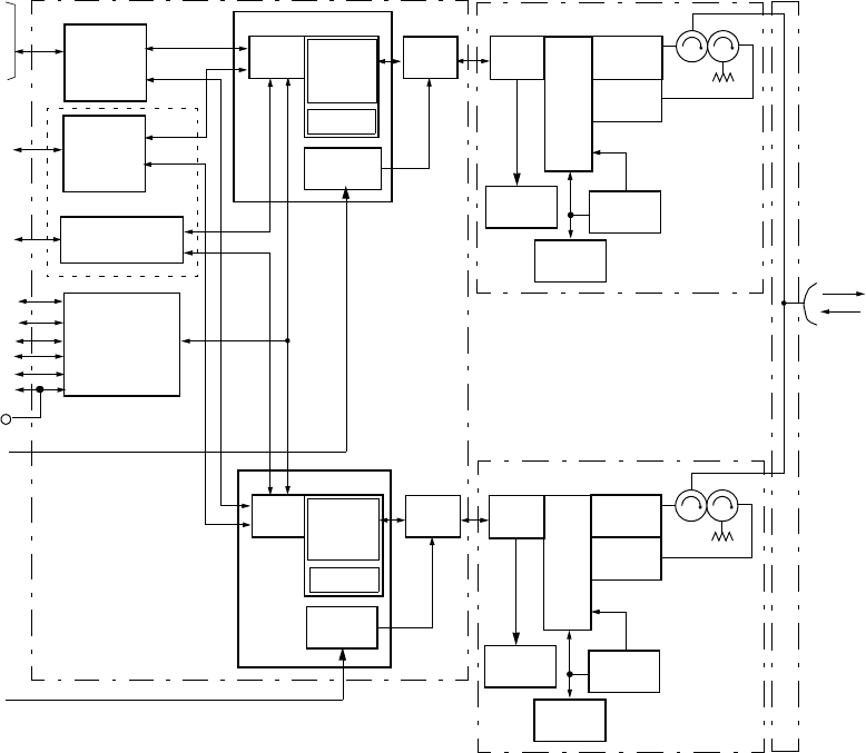
Fig. 2-5 System Block Diagram (2/3)
RF
PS
CKT
SYNTH
(LO)
CTRL
ODU
BPF
(TX)
BPF
(RX)
ODU
INTFC
RF
PS
CKT
SYNTH
(LO)
CTRL
ODU
BPF
(TX)
BPF
(RX)
ODU
INTFC
fH(L)
fL(H)
6 to 38 GHz
HYB
IN/OUT
( )INTFC *1
CTRL
NMS
LCT
EOW
MODEM
DC-DC
CONV
LAN/WS INTFC *3
SC-LAN
IDU
ALM IN/OUT
OC-3 (OPT)/
ODU
INTFC
DPU/
FEC
SC IN/OUT
NE
128QAM/
MODEM
( )INTFC *2
OC-3 (OPT)
2-PORT LAN
GbE
EOW
(JACK)
MODEM
DC-DC
CONV
ODU
INTFC
DPU/
FEC
MODEM
128QAM/
1+1 CONFIGURATION FOR SONET
LPF/EQL
LPF/EQL
PS IN
PS IN
Notes: *1 :Optional
*2:Provides for APS
*3:Provides for auxiliary signals
SYSTEM CONFIGURATION AND CHARACTERISTICS ROI-S05748
2-12
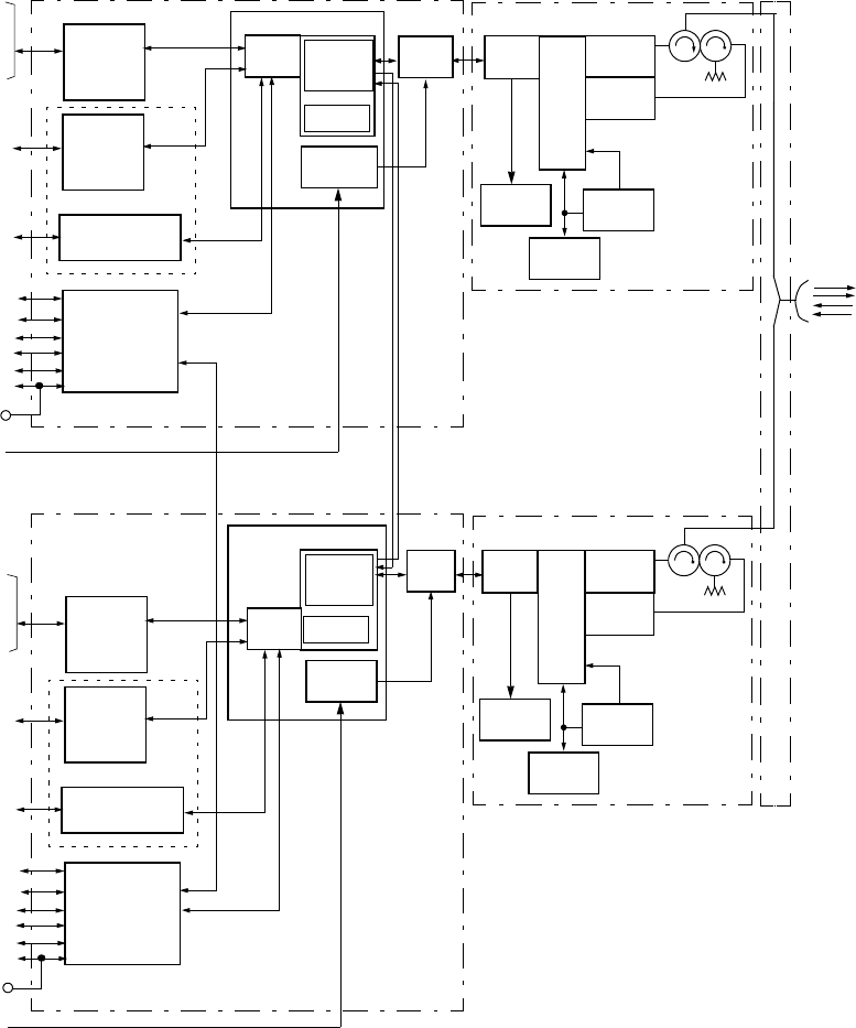
Fig. 2-5 System Block Diagram (3/3)
RF
PS
CKT
SYNTH
(LO)
CTRL
ODU
BPF
(TX)
BPF
(RX)
ODU
INTFC
1+0 CONFIGURATION FOR XPIC SONET
RF
PS
CKT
SYNTH
(LO)
CTRL
ODU
BPF
(TX)
BPF
(RX)
ODU
INTFC
fH(L)
fL(H)
6 to 38 GHz
OMT
IN/OUT
( )INTFC *1
CTRL
NMS
LCT
EOW
MODEM
DC-DC
CONV
LAN/WS INTFC *3
SC-LAN
IDU
ALM IN/OUT
OC-3 (OPT)/
ODU
INTFC
DPU/
FEC
SC IN/OUT
NE
128QAM/
MODEM
( )INTFC *2
OC-3 (OPT)
2-PORT LAN/
GbE
EOW
(JACK)
MODEM
DC-DC
CONV
ODU
INTFC
DPU/
FEC
MODEM
128QAM/
H(V)
V(H)
V(H)
H(V)
IN/OUT
( )INTFC *1
CTRL
NMS
LCT
EOW
LAN/WS INTFC *3
SC-LAN
ALM IN/OUT
OC-3 (OPT)/
SC IN/OUT
NE
( )INTFC *2
OC-3 (OPT)
2-PORT LAN
GbE
EOW
(JACK)
IDU
LPF/EQL
LPF/EQL
PS IN
PS IN
Notes: *1 :Optional
*2:Provides for APS
*3:Provides for auxiliary signals
ROI-S05748 SYSTEM CONFIGURATION AND CHARACTERISTICS
2-13
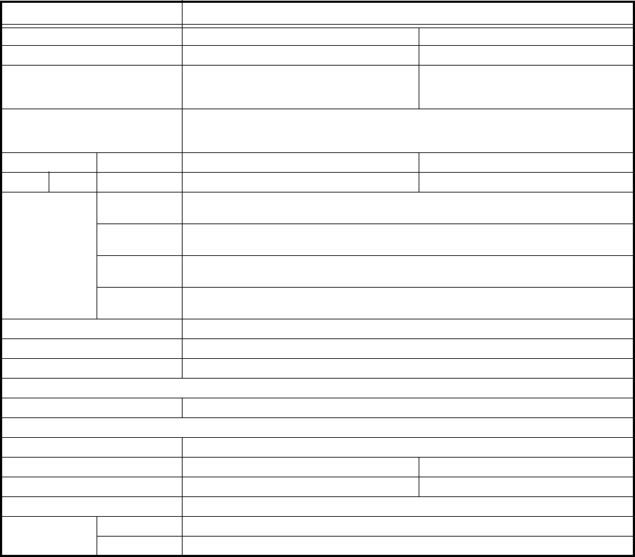
Table 2-0 System Performance Characteristics
STANDARD (STD)
ITEM SONET LAN
Capacity 155 Mbps *2 Up to 150 Mbps
Interface Optical: LC
Up to 2 × OC-3 *3
RJ-45 (2 Ports): 10/100 BASE-T(X)
RJ-45: 1000 BASE-T
LC: 1000 BASE-SX
Interconnecting Connector, Cable
impedance and Cable length
(IDU-ODU)
ODU side: N type female, 50 ohms (Coaxial)
IDU side: TNC type female, 50 ohms (Coaxial)
300m (in case 8D-FB cable or equivalent cable)
Channel Spacing * 32QAM LAN Not Applicable
128QAM 28 (27.5) MHz 28 (27.5) MHz
Environmental
Requirement
Guaranteed
Operation
ODU: −33 to +50°C
IDU: −5 to +50°C
Workable
Operation
ODU: −40 to +55°C
IDU: −10 to +55°C
Transportation/
Storage
ODU, IDU: −40 to +70°C
Relative
humidity
ODU: 100% applicable
IDU: Less than 90% at +50°C (Non-condensing)
EMC Conforms to EN301 489-4
Safety Conforms to EN60950
Power Requirement −48 VDC (−40.5 to −57 VDC), Conforms to EN300 132-2
Power Consumption (Typical)
ODU/Unit 30 W (6 to 11GHz), 23 W (13 to 52 GHz)
IDU Card/Unit
MODEM 10 W
OC-3 INTFC 5 W -
LAN INTFC - 5 W
CTRL 7 W
Mechanical
Dimension
ODU 237(W) × 237(H) × 101(D): Approx. 3.5 kg/Unit
IDU 482(W) × 44(H) × 240(D): Approx.4 kg
Notes *1: 27.5 MHz is applied for 18 GHz.
*2: 2 × 155Mbps using 2 sets for XPIC
*3: 2 for APS configuration
SYSTEM CONFIGURATION AND CHARACTERISTICS ROI-S05748
2-14
2.2 Performance Charactersitics
2.2.1 General System
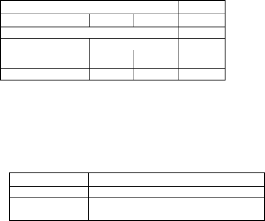
(3) 4 Port LAN
Table 2-1 4 Port LAN 100 Mbps (32QAM)
LAN Setting Capacity *
Port 1 Port 2 Port 3 Port 4 LAN [Mbps]
P1 - P4 = 100 M shared 100
P1 & P2=50M separated P3 & P4=50M separated 100
P1 = 25M
separated
P2 = 25M
separated
P3 = 25M
separated
P4 = 25M
separated
100
Disabled Disabled Disabled Disabled 0
ROI-S05748 SYSTEM CONFIGURATION AND CHARACTERISTICS
2-15
Note: * Total capacity: 108 Mbps.
2.2.2 LAN Interface (1000 Base-SX/1000 Base-T) (GbE)
Table 2-2 GbE LAN
Type 1000 Base-SX (IEEE 802.3z) 1000 Base-T (IEEE 802.3ab)
Throughput 150 Mbps 150 Mbps
Connector type LC RJ-45
Port Number 1 port 1 port
SYSTEM CONFIGURATION AND CHARACTERISTICS ROI-S05748
2-16
2.2.3 Service Channel (SC)
• SC1 to SC4 : RS-232C, 9.6 kbps async.,
: V.11, 64 kbps (Contra/Co-directional: Selectable)
• SC5 : EOW 1 channel
• Connector : High Density D-sub 44 ways
• LAN Interface : SC LAN Interface
(throughput: 64/128/256 kbps)
2.2.4 LCT (PNMT) Interface
• Serial Interface : Connector type USB-B
2.2.5 PNMS Interface
• 10 Base T : Connector RJ-45
2.2.6 RF I/O Port
• Interface Port Type:
Antenna direct mount interface:exclusive NEC flange (11-38 GHz)
is attached to the RF IN/OUT port in
standard
Coaxial cable interface : 6/7/8 GHz: N (Female)
Waveguide feeder interface* (Remote mount):
6 GHz: PDR70
7/8 GHz: PDR84
10/11 GHz: PDR100
13 GHz: PBR120 or PBR140
15 GHz: PBR140
18/23 GHz: PBR220
26 GHz: PBR260
28/32/38 GHz: PBR320
Polarization : Field changeable (Vertical or Horizontal)
Note: For the ODU of waveguide connection type, waveguide flange
adapter is attached to the RF IN/OUT port of remote mount ODU
in standard.
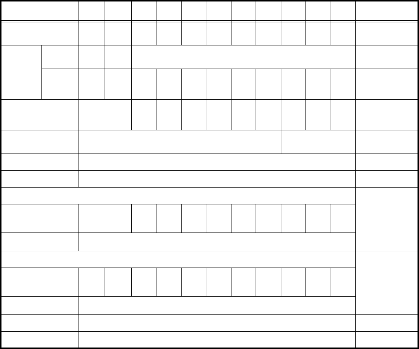
Table 2-3 System Performance for 32QAM/ODU
Frequency Band (GHz) 67-8 10-11 13 15 18 23 26 28 32 38 Guaranteed
Range [GHz] 5.925-
7.11
7.12-
8.5
10.15-
11.7
12.75-
13.25
14.25-
15.35
17.7-
19.7
21.3-
23.6
24.25-
27.5
27.5-
29.5
31.8-
33.4
37.0-
40.0
−
Interface
type
Direct
Mount
N/A N/A NEC Original −
Remote
mount*2
N type
or
PDR 70
N type
or
PDR 84
PDR
100
PBR
120
PBR
140
PBR
220
PBR
220
PBR
260
PBR
320
PBR
320
PBR
320
−
Output Power, nominal
(dBm) (Measured at ODU
output port)
+25 +21 +21 +21 +19 +19 +18 +18 +17 +14.5 6-28G:±1.5 dB
32-38G:+1.5/−2.5 dB
Power Control (1 dB step,
variable)
0 to 23 dB*3
0 to 23 dB*4 ±1.0 dB
ATPC (1 dB step) 0 to 23 dB*4 −
Frequency Stability ± 6 ppm ±10 ppm
Threshold Level (dBm), (Measured at ODU input port) at BER = 10-6 +3.0 dB
Channel Separation (CS)=
28 (27.5) *1 MHz
−75.5 −74.5 −74.5 −75 −75 −74.5 −74.5 −73 −73 73
BER = 10-3 Above value −1.5 dB
System Gain (dB), (Measured at ODU input port) at BER = 10-6−3.0 dB
Channel Separation (CS)=
28 (27.5) *1 MHz
100.5 95.5 95.5 96 94 94 92.5 92.5 92.5 90 87.5
BER = 10-3 Above value +1.5 dB
Maximum Input Level −20 dBm for the BER less than 10-3−
Residual BER Less than 10-12 at RSL=−30 dBm −
ROI-S05748 SYSTEM CONFIGURATION AND CHARACTERISTICS
2-17
*1 27.5 MHz is applied for 18 GHz.
*2 For the ODU of waveguide connection type, flange adapter
is attached to the RF IN/OUT port of remote mount ODU in
standard.
*3 Additional attenuation (5 dB maximum) is available.
*4 Additional attenuation is unavailable.
2.2.7 ODU (Outdoor Unit) and System Performance
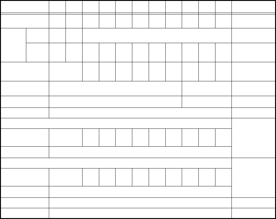
Table 2-4 System Performance for 128QAM/ODU
Frequency Band (GHz) 67-8 10-11 13 15 18 23 26 28 32 38 Guaranteed
Range [GHz] 5.925-
7.11
7.12-
8.5
10.15-
11.7
12.75-
13.25
14.25-
15.35
17.7-
19.7
21.3-
23.6
24.25-
27.5
27.5-
29.5
31.8-
33.4
37.0-
40.0
−
Interface
type
Direct
Mount
N/A N/A NEC Original −
Remote
mount *2
N type
or
PDR 70
N type
or
PDR 84
PDR
100
PBR
120
PBR
140
PBR
220
PBR
220
PBR
260
PBR
320
PBR
320
PBR
320
−
Output Power, nominal
(dBm) (Measured at ODU
output port)
+25 +21 +21 +21 +19 +19 +18 +18 +17 +14.5 6-26G:±1.5 dB
28-38G:+1.5/−2.5 dB
Power Control (1 dB step,
variable)
0 to 20 dB*3 0 to 20 dB*4 ±1.0 dB
ATPC range) 0 to 20 dB*4 0 to 20 dB*4 −
Frequency Stability ± 6 ppm ±10 ppm
Threshold Level (dBm), (Measured at ODU input port) at BER = 10-6 +3.0 dB
Channel Separation (CS)=
28 (27.5)*1 MHz
−69.5 −68.5 −68.5 −69 −69 −69 −68.5 −68.5 −67 −67
BER = 10-3 Above value −1.5 dB
System Gain (dB), (Measured at ODU input port) at BER = 10-6−3.0 dB
Channel Separation =
28 (27.5)*1 MHz
94.5 89.5 89.5 90 88 88 86.5 86.5 84 81.5
BER = 10-3 Above value +1.5 dB
Maximum Input Level −20 dBm for the BER less than 10-3−
Residual BER Less than 10-12 at RSL=−30 dBm −
SYSTEM CONFIGURATION AND CHARACTERISTICS ROI-S05748
2-18
*1 27.5 MHz is applied for 18 GHz.
*2 For the ODU of waveguide connection type, flange adapter
is attached to the RF IN/OUT port in standard.
*3 Additional attenuation (5 dB maximum) is available.
*4 Additional attenuation is unavailable.
Note: XPIC system has the same condition as above.

ROI-S05748 SYSTEM CONFIGURATION AND CHARACTERISTICS
2-19
2.2.8 IDU (Indoor Unit) and System performance
Table 2-5 System Performance for IDU
No. Item
Specification
SONET LAN
1IDU type 1+0 Expandable/1+1
2Modulation Type 128QAM 32/128QAM
3Baseband Interface 155.52 Mbps ±20 ppm 10/100 Base-T(X)
1000 Base-SX
1000 Base-T
75 ohm/S-1.1/L-1.1
IEC 169-29 (1.0/2.3) RJ-45 (10/100/1000 Base-T(X))
LC (1000 Base-SX)
Channel Number 1/2* 1/2
Total Capacity 155 Mbps 100+50,
75+75 Mbps
4Service Channels V.11 (Contra/Co-directional) × 2 channels, RS-232C × 2 channels
5EOW IDU-IDU
6External alarm &
House keeping
See table below
7Security level by LCT 2 levels
8Control &Setting by
LCT/PNMT
Serial Interface (USB connector)
Loop Back a) Far End Baseband Loop Back
b) Near End Baseband Loop Back
c) IF Loop back
BER Alarm Adjustable 10-3/ 10-4/ 10-5 (High BER) 10-6/ 10-7/ 10-8/ 10-9 (Low BER)
Frequency setting Direct entry or Table Download entry: Available when using PNMx (optional)
TX output Control Manual control, Automatic control, Mute control
9Performance
monitoring (PMON)
/Metering
PMON Items;
a) OFS, b) BBE, c) ES, d) SES, e) UAS
Metering Items
a) Output power level (TX PWR), b) Received signal level (AGC V) c) Bit error rate (BER MON)
LAN monitoring Items;
a) RX Unicast, b) RX Broadcast, c) RX Multicast, d) RX Pause, e) RX CRC error
10 LED Display CTRL IDU Alarm (Red)
Maintenance (Amber)
Memory Access (Amber)
MODEM Operating PWR (Green)
ODU Alarm (Red)
MD/CBL Alarm (Red)
TX status (Green)
RX status (Green)
XPIC Reset (Amber)*
SONET INTFC Module alarm (Red)
Online (Green)**
LAN INTFC Module alarm (Red)
* This value is available with 2 IDUs per 1 RF CH with
XPIC system.
** This indicates the online status which is selected from
Working/Standby in APS system or Working in w/o APS
system.
SYSTEM CONFIGURATION AND CHARACTERISTICS ROI-S05748
2-20
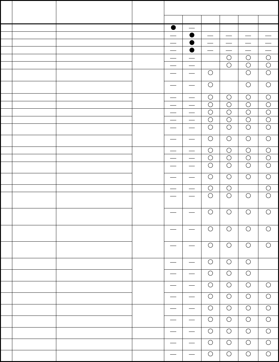
Table 2-6 Alarm & House Keeping Output Items
#
Alarm Item
displayed
on LCT/PNMT
Condition
ALM LED
Indication
(IDU’s front)
Summarized Alarm Output
(Form-C) <Note 1,2,3,7>
RL1 RL2 RL3 RL4 RL5 RL6
1MAINT System under maintenance MAINT MASK MASK MASK MASK
2IDU CPU ALM IDU CPU failure -
3PS ALM1 PS1 failure (only1+1) PWR
4PS ALM2 PS2 failure (only1+1) -
5ODU ALM1 ODU1 total alarm ODU √
6ODU ALM2 ODU2 total alarm √
7ODU CPU/CBL
OPN ALM1 ODU1 CPU failure or IF cable is
open
ODU
Blinking √
8ODU CPU/CBL
OPN ALM2 ODU2 CPU failure or IF cable is
open
√
9TX PWR ALM1 ODU1 output power decrease ODU
10 TX PWR ALM2 ODU2 output power decrease
11 TX INPUT ALM1 ODU1 TX IF input level decrease ODU
12 TX INPUT ALM2 ODU2 TX IF input level decrease
13 APC ALM1 ODU1 LO OSC APC loop out of
lock
ODU
14 APC ALM2 ODU2 LO OSC APC loop out of
lock
15 RX LEV ALM1 ODU1 Receiving level decrease ODU
16 RX LEV ALM2 ODU2 Receiving level decrease
17 IF CABLE SHORT
ALM1
IF Cable connected to ODU1 short IDU
MD/CBL
Blinking
18 IF CABLE SHORT
ALM2
IF Cable connected to ODU2 short
19 IDU ALM IDU total alarm IDU √
20 MOD ALM1 MOD PLL APC loop out of lock,
MOD output level down or TX
DPU CLK loss in MODEM1
IDU
MD/CBL
21 MOD ALM2 MOD PLL APC loop out of lock,
MOD output level down or TX
DPU CLK loss in MODEM2
22 DEM ALM1 Carrier Asynchronous,
Frame Asynchronous at DPU in
MODEM1
IDU
MD/CBL
23 DEM ALM2 Carrier Asynchronous,
Frame Asynchronous at DPU in
MODEM2
24 HIGH BER ALM1 BER > 10E-3 to -5 (selectable) in
MODEM1
IDU
MD/CBL √
25 HIGH BER ALM2 BER > 10E-3 to -5 (selectable) in
MODEM2 √
26 LOW BER ALM1 BER > 10E-6 to -9 (selectable) in
MODEM1
IDU
MD/CBL
27 LOW BER ALM2 BER > 10E-6 to -9 (selectable) in
MODEM2
28 LOF1 Loss of Radio frame
synchronization in MODEM1
IDU
MD/CBL
29 LOF2 Loss of Radio frame
synchronization in MODEM2
30 OC-3(1/2) LOS
(MUX)
Loss of input data stream
from MUX <Note 1>
IDU INTFC
<Note5>
31 OC-3(1/2) LOS
(DMR)
Loss of input data stream
from DMR <Note 1>
IDU INTFC
<Note5>
32 OC-3(1/2) TF
ALM
Loss of OC-3 signal output to
MUX <Note 1>
IDU INTFC
<Note5>
ROI-S05748 SYSTEM CONFIGURATION AND CHARACTERISTICS
2-21
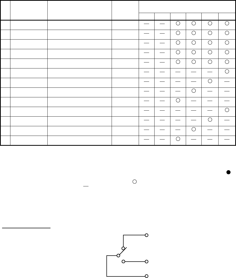
Note 1: It is not possible to change capacity between OC-3 and Ethernet under working
condition.
Note 2: In MAINT status, excepting HK-OUT and Cluster ALM, alarm outputs are masked
to normal condition.
Note 3: The summarization of alarm outputs is fully user programmable; The sign in
above table shows fixed item and can not be changed. The sign √ only shows the
factory settings. The sign output can be assigned for plural items. The sign
input/output can not be assigned. Either HK output or Cluster ALM output
in each channel can be assigned.
Note 4: Above Table shows Alarm output matrix for 1+1 configuration
Note 5: Only apply to SONET system.
Note 6: Only apply to XPIC system.
Note 7: Assign to relays 3 to 6 only one category, either NLite E Alarm, House Keeping
Control out or Cluster Alarm out.
Output Port condition
Interface circuit: Relay Form C
Maximum Current: 0.2 A
Maximum Voltage: 100 V (AC+DC)
Event/ Alarm Open
(Normally closed)
Event/ Alarm Close
(Normally open)
COM
Relay
33 INTFC (1/2) LAN
LINK PORT
Loss of SC LAN Link IDU INTFC
<Note5>
34 XCTRL ALM1 Control failure or REF
Signal failure
IDU INTFC
<Note6>
35 XCTRL ALM2 Control failure or REF
Signal failure
IDU INTFC
<Note6>
36 XREF ALM1 Control failure or REF
Signal failure
IDU INTFC
<Note6>
37 XREF ALM2 Control failure or REF
Signal failure
IDU INTFC
<Note6>
38 HK-OUT1 House keeping Control out1 Only show
PNMT
39 HK-OUT2 House keeping Control out2 Only show
PNMT
40 HK-OUT3 House keeping Control out3 Only show
PNMT
41 HK-OUT4 House keeping Control out4 Only show
PNMT
42 Cluster ALM out1 This item received from
opposite site. Item 1
Only show
PNMT
43 Cluster ALM out2 This item received from
opposite site. Item 2
Only show
PNMT
44 Cluster ALM out3 This item received from
opposite site. Item 3
Only show
PNMT
45 Cluster ALM out4 This item received from
opposite site. Item 4
Only show
PNMT
Table 2-6 Alarm & House Keeping Output Items (Cont’d)
#
Alarm Item
displayed
on LCT/PNMT
Condition
ALM LED
Indication
(IDU’s front)
Summarized Alarm Output
(Form-C) <Note 1,2,3,7>
RL1 RL2 RL3 RL4 RL5 RL6
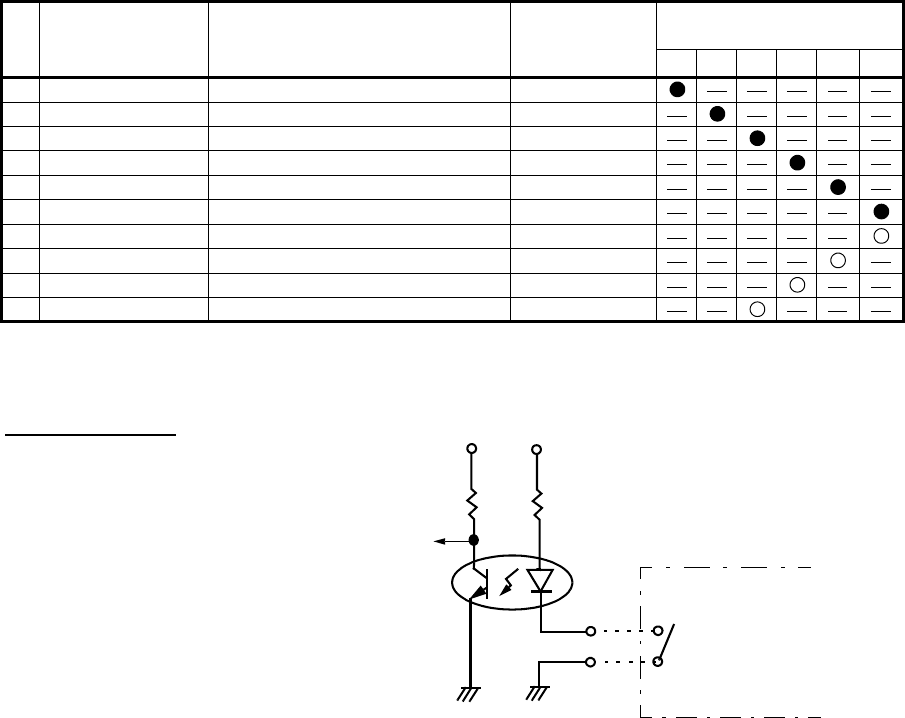
Table 2-7 House keeping input Items
#
House keeping Item
displayed
on LCT/PNMT
Condition Event Indication
Summarized Alarm Input
(Photo coupler)
IN1 IN2 IN3 IN4 IN5 IN6
1HK-IN1 House keeping Event inport1 Only show PNMT
2HK-IN2 House keeping Event inport2 Only show PNMT
3HK-IN3 House keeping Event inport3 Only show PNMT
4HK-IN4 House keeping Event inport4 Only show PNMT
5HK-IN5 House keeping Event inport5 Only show PNMT
6HK-IN6 House keeping Event inport6 Only show PNMT
7Cluster ALM input1 This item transmits to opposite site. Item 1 Only show PNMT
8Cluster ALM input2 This item transmits to opposite site. Item 2 Only show PNMT
9Cluster ALM input3 This item transmits to opposite site. Item 3 Only show PNMT
10 Cluster ALM input4 This item transmits to opposite site. Item 4 Only show PNMT
SYSTEM CONFIGURATION AND CHARACTERISTICS ROI-S05748
2-22
Note 1: Unused channel/interface is masked according to the bit rate.
Note 2: In the 2-WAY mode, Cluster ALM is transmitted in parallel for DIR-A and DIR-B.
Normally Open
Control Closed
+3.3 V +3.3 V
Input Port condition
Normal OPEN (> 200 k ohms)
Control CLOSE (< 50 ohms)
Interface circuit: photo coupler with bias circuit
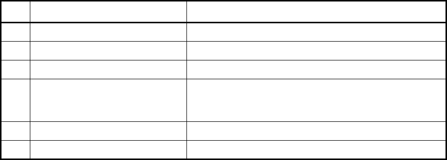
ROI-S05748 SYSTEM CONFIGURATION AND CHARACTERISTICS
2-23
2.3 Interconnection between ODU and IDU
Table 2-8 IF Cable
No. Item Specification
1Interconnection Single coaxial cable /50 ohms
2Standard Type of Cable 5D-FB, 8D-FB (standard), 10D-FB
3Signals IF signal, alarms, control, monitoring and power source
4Maximum Cable Length 150 m (5D-FB)
300 m (8D-FB)
350 m (10D-FB)
5Cable Equalization Automatic level equalization
6Guaranteed temperature range −33°C to +50°C (workable : −40°C to +55°C)
Note 1 : In case of employing hitless protection, set each length
of two IF cables same or the difference of their cable
length shall be less than 100 meters.
Note 2 : Salt damage (custom order)
In case of operating in the sea or around the coast area
(within 3 km from coastline), measure must be taken for
the ODU against salt damage. Please contact NEC for
the countermeasure.
Note 3 : Water Proof N type connector
The waterproof N type connectors must be used for IF
cable of ODU side, because DC voltage power is
supplied in it.
Note 4 : IDU IF connector = TNC (Female),
ODU IF connector = N (Female)
Note 5 : TNC (Male) L-angle connector for the 8D-FB IF cable
is used to connect it to the IDU. When the N (Male)
straight connector is attached to the 5D-FB or 10D-FB
IF cable, the TNC (Male) - N (Female) L-angle adapter
is used.
SYSTEM CONFIGURATION AND CHARACTERISTICS ROI-S05748
2-24
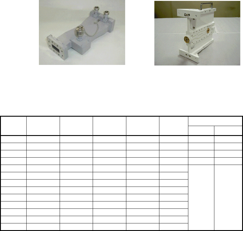
2.4 Hybrid Combiner/Divider
There are two types of hybrid combiner/divider used in 1+1 protected
systems, one is coaxial cable connection type for 6/7/8 GHz Bands and the
other is ODU Direct Mount type for 11 - 38 GHz Bands. The following
NEC Hybrid Combiner/Divider is suited for Andrew or RFS Antenna, and
all NEC ODUs.
6/7/8 GHz Hybrid 11 - 52 GHz Hybrid
Fig. 2-6 Hybrid
Table 2-9 Characteristics
Frequency
Band
[GHz]
Frequency
Range
[GHz]
1-2 PORT
Var ia ti o n
Max.(dB)
Loss Max.
(dB)
Isolation
Min.(dB) VSWR Max. Interface
(ANT Side) (ODU Side)
L6 5.925 -6.425 0.5 3.7 20 1.3 UDR70 N Connector
U6 6.43 -7.11 0.5 3.7 20 1.3 UDR70 N Connector
77.125 -7.9 0.5 3.7 20 1.3 UDR84 N Connector
87.7 -8.5 0.5 3.7 20 1.3 UDR84 N Connector
11 10.5 -11.7 0.5 3.5 20 1.2
NEC
original
NEC
original
13 12.75 -13.25 0.5 3.5 20 1.2
15 14.5 -15.35 0.5 3.5 20 1.2
18 17.7 -19.7 0.5 3.5 20 1.2
23 21.2 -23.6 0.5 3.5 20 1.2
26 24.5 -26.5 0.5 3.8 20 1.2
32 31.8 -33.4 0.5 3.8 20 1.2
38 37 -39.5 0.5 3.8 20 1.2
* Custom ordered for 28 GHz.
ROI-S05748 SYSTEM CONFIGURATION AND CHARACTERISTICS
2-25
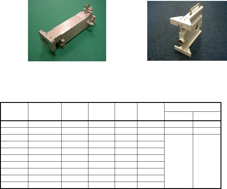
2.4.1 10 dB Coupler
There are two types of NEC 10 dB Coupler; one is coaxial cable
connection type for 6/7/8 GHz bands and the other is ODU Direct Mount
type for 11 - 38 GHz Bands. The following 10 dB Coupler is suited for
Andrew or RFS Antenna, and all NEC ODUs.
6/7/8 GHz Coupler (N-Type) 11 - 38 GHz Coupler
Fig. 2-7 10 dB Coupler
Table 2-10 Characteristics
Frequency
Band
[GHz]
Frequency
Range
[GHz]
1-2 PORT
Variation
Max.(dB)
Loss Max.
(dB)
Isolation
Min.(dB) VSWR Max. Interface
(ANT Side) (ODU Side)
L6/U6 5.925 -7.125 0.5 1.2 20 1.3 UDR70 N Connector
7/8 7.125 - 8.5 0.5 1.2 20 1.3 UDR84 N Connector
11 10.5 - 11.7 0.5 1.2 20 1.2
NEC original NEC original
13 12.75 -13.25 0.5 1.2 20 1.2
15 14.5 -15.35 0.5 1.2 20 1.2
18 17.7 -19.7 0.5 1.2 20 1.2
23 21.2 -23.6 0.5 1.2 20 1.2
26 24.5 -26.5 0.5 1.2 20 1.2
32 31.8 - 33.4 0.5 1.2 20 1.2
38 37 -39.5 0.5 1.2 20 1.2
* ODU for 6/7/8 GHz: Separate Type
* ODU for 11 - 38 GHz: Direct Mount Type
* Custom ordered for 28 GHz.
SYSTEM CONFIGURATION AND CHARACTERISTICS ROI-S05748
2-26
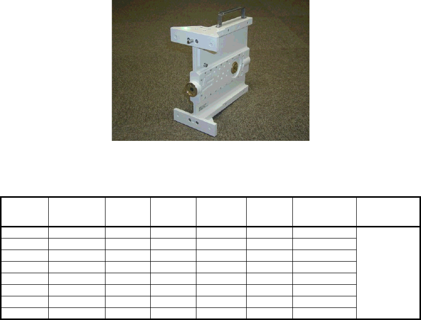
2.4.2 OMT (Ortho-Mode Transducer)
The OMT enables dual polarization feature to double the transmission
capacity for the NLite E system using the same frequency. The following
NEC OMT has ODU Direct Mount type for 11-38 GHz Bands, which is
suited for RFS Antenna and all NEC ODUs.
Fig. 2-8 OMT Transducer
Table 2-11 Characteristics
Frequency
Band
[GHz]
Frequency
Range
[GHz]
XPD Min.
[dB]
LOSS Max.
[dB]
P-P
ISOLATION
Min.[dB]
VSWR Max. INTERFACE WG
INNER DIA. (mm)
(ANT Side)
INTERFACE (ODU
Side)
11 10.5 -11.7 35 0.6 38 1.3 18.0
NEC original
13 12.75 -13.25 35 0.6 38 1.3 15.0
15 14.5 -15.35 35 0.6 38 1.3 13.5
18 17.7 -19.7 35 0.6 38 1.3 10.5
23 21.2 -23.6 35 0.6 38 1.3 9.0
26 24.5 -26.5 35 0.8 38 1.3 8.0
32 31.8 -33.4 35 1.0 38 1.3 6.5
38 37 -39.5 35 1.0 38 1.3 5.5

ROI-S05748 SYSTEM CONFIGURATION AND CHARACTERISTICS
2-27
2.5 RF Channel Plan
Radio frequencies in 6 to 38 GHz applicable to NLite E are shown in the
following Table: For details of frequency range in each Sub Band RF
frequency band listed below, refer to the Appendix attached in this Section
1.
Table 2-12 RF Frequencies
RF BAND [GHz] Tx-Rx Shift Frequency [MHz]
L6 GHz :5.925 - 6.425 252.04/
266
U6 GHz :6.43 -7.11 340
7 GHz :7.125 -7.9 154/
161/
196/
245
8 GHz :7.7 -8.5 119/
126/
151.614/
154/
266/
294.44/
305.56/
310
311.32
11 GHz :10.15 -11.7 490
13 GHz :12.75 -13.25 266
15 GHz :14.5 -15.35 315/
420/
470/
490/
644/
728
18 GHz :17.7 -19.7 340/
1560
23 GHz :21.2 -23.6 1200
26 GHz :24.5 -26.5 855/
1008/
1123.5
28 GHz :27.5 -29.5 1008
32 GHz :31.8 -33.4 812
38 GHz :37 -39.5 700/
1000/
1260/
SYSTEM CONFIGURATION AND CHARACTERISTICS ROI-S05748
2-28
2.6 Power Supply
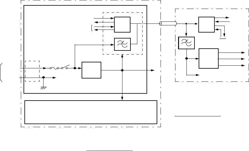
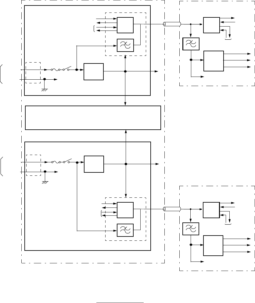
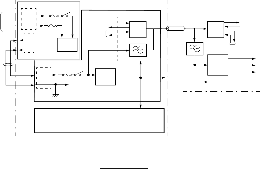
The power supply systems are shown in Fig. 2-9 (1/3) to (3/3). The DC-
DC CONV module in the MODEM module produces regulated +3.6 V DC
from −48 V *1 DC input for the component modules on the IDU. Also,
this module supplies a −48 V DC to the ODU.
The DC V to the ODU is supplied through the coaxial cable which is also
used for the IF and other signals. The PS circuit on the ODU produces +7/
+8/+9/−7/−8/−9 * and −15 V DC for the component modules from the −48
V DC supplied from the IDU.
Note: *: Necessary voltages in the ODU vary depending on the ODU
type.
DC
INPUT (1/3)
(2/4)
ODU (NEO)
PS
SELV
−48 V
TX IF
−15 V
MODEM
DC-DC
IDU
−48 V
SEP/
COMB
FIL
CTRL, OC-3 INTFC, LAN INTFC, GbE INTFC
CONV
ODU INTFC
G
−48 V SEP/
COMB
FIL
RX IF
SV/CTRL
TX IF
RX IF
SV/CTRL
FUSE
PWR
−7/−8/−9 V
+7/+8/+9 V
−48 V
*1
*1
*2
Notes: *1: The inner voltages vary depending on the ODU type.
*2: Optional
For 1+0 Configuration
For 1+0 Configuration
+3.6 V
−48 V
Fig. 2-9 Power Supply System Block Diagram (1/3)
DC
INPUT (1/3)
(2/4)
ODU (NEO)
SELV
−48 V
TX IF
−15 V
MODEM
DC-DC
IDU
−48 V
SEP/
COMB
FIL
CTRL, OC-3 INTFC, LAN INTFC, GbE INTFC
CONV
ODU INTFC
G
−48 V SEP/
COMB
FIL
RX IF
SV/CTRL
TX IF
RX IF
SV/CTRL
FUSE
PWR
−7/−8/−9 V
+7/+8/+9 V
−48 V
*1
*1
DC
INPUT (1/3)
(2/4)
ODU (NEO)
SELV
−48 V
TX IF
−15 V
MODEM
DC-DC
−48 V
SEP/
COMB
FIL
CONV
ODU INTFC
G
−48 V SEP/
COMB
FIL
RX IF
SV/CTRL
TX IF
RX IF
SV/CTRL
FUSE
PWR
−7/−8/−9 V
+7/+8/+9 V
−48 V
*1
*1
Notes: *1: The inner voltages vary depending on the ODU type.
*2: Optional
For 1+1 Configuration
*2
PS
PS
+3.6 V
+3.6 V
ROI-S05748 SYSTEM CONFIGURATION AND CHARACTERISTICS
2-29
Fig. 2-9 Power Supply System Block Diagram (2/3)
DC
INPUT
(1/3)
(2/4)
ODU (Excepting NEO)
PS
SELV
(−)
TX IF
−15 V
MODEM
DC-DC
IDU
−43 V
SEP/
COMB
FIL
CTRL, OC-3 INTFC, LAN INTFC, GbE INTFC
CONV
ODU INTFC
(+) −43 V SEP/
COMB
FIL
RX IF
SV/CTRL
TX IF
RX IF
SV/CTRL
FUSE
PWR
+3.6 V
−7/−8/−9 V
+7/+8/+9 V
−43 V
*1
*1
Notes: *1: The inner voltages vary depending on the ODU type.
*2: Optional
DC-DC
CONV
(1/3)
(2/4)
SELV
FUSE
PWR
FUSE
−20 to −60 V/
+20 to +60 V
(1)
(2) −43 V
OUT
G
*2
DC-DC CONV
*2
For 1+0 Configuration
Connecting Other Type NLite E ODU
SYSTEM CONFIGURATION AND CHARACTERISTICS ROI-S05748
2-30
Fig. 2-9 Power Supply System Block Diagram (3/3)

ROI-S05754-05AE CONTENTS
August, 2007
CL-1
NLite E
6-38 GHz SONET DIGITAL RADIO SYSTEM
APPENDIX
RADIO FREQUENCY PLAN FOR NLite E
CONTENTS
TITLE PAGE
L6 GHz Band ...................................................................................... A-3
Table A-1 L6 GHz, Sub-band E versus Frequency Range
(TX-RX frequency spacing: 252.04 MHz):
STANDARD ...................................................................... A-3
Table A-2 L6 GHz, Sub-band F versus Frequency Range
(TX-RX frequency spacing: 266 MHz):
OIRT.................................................................................. A-4
11 GHz Band ...................................................................................... A-5
Table A-3 11 GHz, Sub-band A/B/C/D versus Frequency
(TX-RX frequency spacing: 490 MHz):
STANDARD ...................................................................... A-5
18 GHz Band ...................................................................................... A-6
Table A-4 18 GHz, Sub-band A versus Frequency Range
(TX-RX frequency spacing: 1560 MHz):
USA/BRAZIL..................................................................... A-6
23 GHz Band ...................................................................................... A-7
Table A-5 23 GHz, Sub-band A/B/C versus Frequency Range
(TX-RX frequency spacing: 1200 MHz):
USA................................................................................... A-7
38 GHz Band ...................................................................................... A-7
Table A-6 38 GHz, Sub-band A/B/C/D/E/F versus Frequency Range
(TX-RX frequency spacing: 1260 MHz):
STANDARD ...................................................................... A-7
ROI-S05754 APPENDIX
A-1
APPENDIX
RADIO FREQUENCY PLAN FOR
NLite E
This provides frequency range used in each RF frequency band (6 to 38
GHz). Refer to Note 1, Note 2 and Note 3 for corresponding frequency
band of the system.
SELECTABLE
MODEM SYSTEM
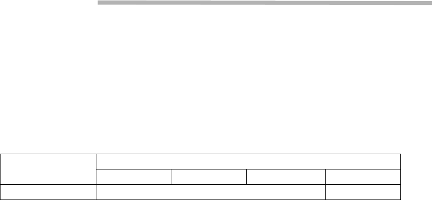
CHANNEL SEPARATION FOR TRAFFIC CAPACITY
3.5 MHz 7 MHz 14 (13.75)* MHz 28 (27.5)* MHz
128QAM −155 MB
Note 1:When 13 to 38 GHz band is applied, each data transmission
system have to take following channel separation or more.
Usually, RF channel frequency must be assigned that is shifted a
half of channel separation from Start and Stop frequency values
within frequency range of Sub Band.
*: 13.75 and 27.5 MHz apply for 18 GHz.
Note 2: When 6/7/8 GHz Band is applied , the TX/RX BPFs are adjusted
to the point frequency which is indicated in the ODU name plate.
Therefore, to change the point frequency over the variable range
the TX/RX BPFs replacement and LCT resetup are required
(excepting Sub Band K/L/M/N/P)*.
* When Sub Band K/L/M/N/P in 6/7/8 GHz Band is applied, RF
channel frequency is assignable depending on the transmission
capacity within frequency range of Sub Band as above Note 1 for
13 to 38 GHz band. Refer to start and stop frequency in the
frequency table corresponded channel separation.
Note3:When 10/11 GHz Band is applied, refer to start and stop
frequency in the frequency table corresponded channel
separation.

APPENDIX ROI-S05754
A-2
The change of the BPF varies depending on the Frequency Band and
Sub Band to be used, so contact NEC before changing the ODU Sub
Band whether the change of the BPF is necessary or not.
Caution: ODUs that have been used outside should NOT be opened.
Silica Gel Packs should be replaced with new ones every
time the customer opens the ODU and also the air leakage
test operation should be performed by using the air leakage
tester (NEC made, sold separately).
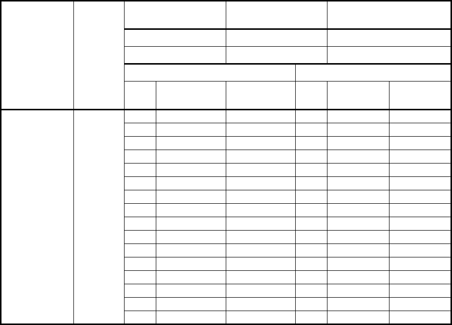
Table A-1 L6 GHz, Sub-band E versus Frequency Range (TX-RX frequency spacing: 252.04 MHz):
STANDARD
Table A-2 L6 GHz, Sub-band F versus Frequency Range (TX-RX frequency spacing: 266 MHz): OIRT
Table A-3 11 GHz, Sub-band A/B/C/D versus Frequency (TX-RX frequency spacing: 490 MHz):
STANDARD
Table A-4 18 GHz, Sub-band A versus Frequency Range (TX-RX frequency spacing: 1560 MHz): USA/
BRAZIL
Table A-5 23 GHz, Sub-band A/B/C versus Frequency Range (TX-RX frequency spacing: 1200 MHz):
USA
Table A-6 38 GHz, Sub-band A/B/C/D/E/F versus Frequency Range (TX-RX frequency spacing: 1260
MHz): STANDARD
ROI-S05754 APPENDIX
A-3
1. L6 GHz Band
Table A-1 L6 GHz, Sub-band E versus Frequency Range
(TX-RX frequency spacing: 252.04 MHz): STANDARD
ODU Type Sub-Band
TX Radio Point
Frequency Range
RX Radio Point
Frequency Range TX HIGH/LOW
NWA-009024( ) E
1 1’
2 2’
3 3’
4 4’
5 5’
6 6’
7 7’
8 8’
9 9’
10 10’
11 11’
12 12’
13 13’
14 14’
15 15’
16 16’
Note: It is required to define point frequency which is to be used. The
BPF for 6/7/8 GHz is set to each frequency though it is within the
same Sub Band. To change the point frequency, not only LCT
setup, but also the change of BPF is needed.
5930.375 to 6152.750 MHz 6182.415 to 6404.790 MHz Lower Band
6182.415 to 6404.790 MHz 5930.375 to 6152.750 MHz Higher Band
TX Low TX High
RF
CH TX Point Freq. RX Point Freq. RF
CH
TX Point
Freq.
RX Point
Freq.
5930.375 6182.415 6182.415 5930.375
5945.200 6197.240 6197.240 5945.200
5960.025 6212.065 6212.065 5960.025
5974.850 6226.890 6226.890 5974.850
5989.675 6241.715 6241.715 5989.675
6004.500 6256.540 6256.540 6004.500
6019.325 6271.365 6271.365 6019.325
6034.150 6286.190 6286.190 6034.150
6048.975 6301.015 6301.015 6048.975
6063.800 6315.840 6315.840 6063.800
6078.625 6330.665 6330.665 6078.625
6093.450 6345.490 6345.490 6093.450
6108.275 6360.315 6360.315 6108.275
6123.100 6375.140 6375.140 6123.100
6137.925 6389.965 6389.965 6137.925
6152.750 6404.790 6404.790 6152.750
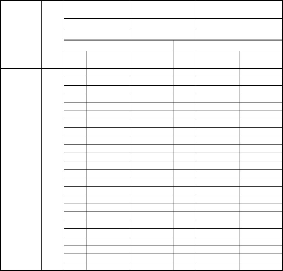
Table A-2 L6 GHz, Sub-band E versus Frequency Range
(TX-RX frequency spacing: 252.04 MHz): MEXICO
ODU Type Sub-
Band
TX Radio Point
Frequency Range
RX Radio Point
Frequency Range TX HIGH/LOW
NWA-009024( ) E
1 1’
2 2’
3 3’
4 4’
5 5’
6 6’
7 7’
8 8’
9 9’
10 10’
11 11’
12 12’
13 13’
14 14’
15 15’
16 16’
17 17’
18 18’
19 19’
20 20’
21 21’
22 22’
23 23’
24 24’
APPENDIX ROI-S05754
A-4
Note: It is required to define point frequency which is to be used. The
BPF for 6/7/8 GHz is set to each frequency though it is within the
same Sub Band. To change the point frequency, not only LCT
setup, but also the change of BPF is needed.
Note: Refer to Note.2 on the first page for 6/7/8 GHz Band.
Note: It is required to define point frequency which is to be used. The
BPF for 6/7/8 GHz is set to each frequency though it is within the
same Sub Band. To change the point frequency, not only LCT
setup, but also the change of BPF is needed.
5935.317 to 6162.633 MHz 6187.357 to 6414.673 MHz Lower Band
6187.357 to 6414.673 MHz 5935.317 to 6162.633 MHz Higher Band
TX Low TX High
RF
CH TX Point Freq. RX Point Freq. RF
CH TX Point Freq. RX Point Freq.
5935.317 6187.357 6187.357 5935.317
5945.200 6197.240 6197.240 5945.200
5955.083 6207.123 6207.123 5955.083
5964.966 6217.006 6217.006 5964.966
5974.850 6226.890 6226.890 5974.850
5984.733 6236.773 6236.773 5984.733
5994.616 6246.656 6246.656 5994.616
6004.500 6256.540 6256.540 6004.500
6014.383 6266.423 6266.423 6014.383
6024.266 6276.306 6276.306 6024.266
6034.150 6286.190 6286.190 6034.150
6044.033 6296.073 6296.073 6044.033
6053.916 6305.956 6305.956 6053.916
6063.800 6315.840 6315.840 6063.800
6073.683 6325.723 6325.723 6073.683
6083.566 6335.606 6335.606 6083.566
6093.450 6345.490 6345.490 6093.450
6103.333 6355.373 6355.373 6103.333
6113.216 6365.256 6365.256 6113.216
6123.100 6375.140 6375.140 6123.100
6132.983 6385.023 6385.023 6132.983
6142.866 6394.906 6394.906 6142.866
6152.750 6404.790 6404.790 6152.750
6162.633 6414.673 6414.673 6162.633
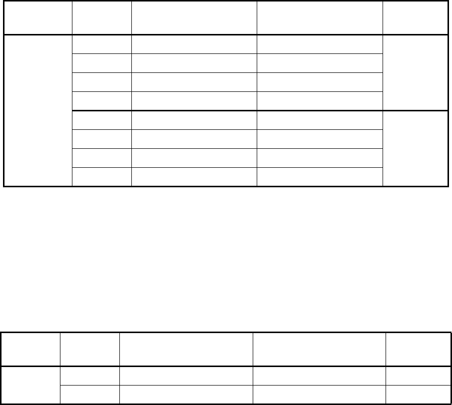
Table A-3 11 GHz, Sub-band A/B/C/D versus Frequency
(TX-RX frequency spacing: 490 MHz): STANDARD
ODU Type Sub-Band TX Radio Point
Frequency Range
RX Radio Point
Frequency Range
TX
HIGH/LOW
NWA-009032( )
A10715 to 10825 MHz 11205 to 11315 MHz
Lower Band
B10835 to 10945 MHz 11325 to 11435 MHz
C10955 to 11065 MHz 11445 to 11555 MHz
D11075 to 11195 MHz 11565 to 11685 MHz
A11205 to 11315 MHz 10715 to 10825 MHz
Higher Band
B11325 to 11435 MHz 10835 to 10945 MHz
C11445 to 11555 MHz 10955 to 11065 MHz
D11565 to 11685 MHz 11075 to 11195 MHz
ROI-S05754 APPENDIX
A-5
2. 11 GHz Band
Note: When the channel separation of 28 MHz applies in the Sub-Band
A, the channel frequency must be assigned within from (Start
frequency + 6 MHz) to (Stop frequency
−
6 MHz).
When the channel separation of 28 MHz applies in the Sub-Band
B/C/D, the channel frequency must be assigned within from (Start
frequency) to (Stop frequency
−
6 MHz).
Table A-4 18 GHz, Sub-band A versus Frequency Range
(TX-RX frequency spacing: 1560 MHz): USA/BRAZIL
ODU Type Sub-Band TX Radio Point
Frequency Range
RX Radio Point
Frequency Range
TX
HIGH/LOW
NWA-
009038( )
A17700 to 18140 MHz 19260 to 19700 MHz Lower Band
A19260 to 19700 MHz 17700 to 18140 MHz Higher Band

Table A-5 23 GHz, Sub-band A/B/C versus Frequency Range
(TX-RX frequency spacing: 1200 MHz): USA
ODU Type Sub-Band TX Radio Point
Frequency Range
RX Radio Point
Frequency Range
TX
HIGH/LOW
NWA-
009040( )
A21200.00 to 21802.00 MHz 22400.00 to 23002.00 MHz
Lower BandB21498.00 to 22100.00 MHz 22698.00 to 23300.00 MHz
C21798.00 to 22400.00 MHz 22998.00 to 23600.00 MHz
A22400.00 to 23002.00 MHz 21200.00 to 21802.00 MHz
Higher BandB22698.00 to 23300.00 MHz 21498.00 to 22100.00 MHz
C22998.00 to 23600.00 MHz 21798.00 to 22400.00 MHz
APPENDIX ROI-S05754
A-6
3. 23 GHz Band
Sub-Band A and C cover full band.

Table A-6 38 GHz, Sub-band A/B/C/D/E/F versus Frequency Range
(TX-RX frequency spacing: 1260 MHz): STANDARD
ODU Type Sub-Band TX Radio Point
Frequency Range
RX Radio Point
Frequency Range
TX
HIGH/LOW
NWA-
009048( )
A/D 37016.00 to 37620.00 MHz 38276.00 to 38880.00 MHz
Lower BandB/E 37316.00 to 37920.00 MHz 38576.00 to 39180.00 MHz
C/F 37616.00 to 38220.00 MHz 38876.00 to 39480.00 MHz
A/D 38276.00 to 38880.00 MHz 37016.00 to 37620.00 MHz
Higher BandB/E 38576.00 to 39180.00 MHz 37316.00 to 37920.00 MHz
C/F 38876.00 to 39480.00 MHz 37616.00 to 38220.00 MHz
ROI-S05754 APPENDIX
A-7
4. 38 GHz Band

ROI-S05750-05HE CONTENTS
August, 2007
CL-1
NLite E
6-38 GHz SONET DIGITAL RADIO SYSTEM
Section III INSTALLATION AND INITIAL LINE UP
CONTENTS
TITLE PAGE
1 GENERAL ••••••••••••••••••••••••••••••••••••••••••••••••••••••••••••• 1-1
2 INSTALLATION •••••••••••••••••••••••••••••••••••••••••••••••••••••• 2-1
2.1 Packages••••••••••••••••••••••••••••••••••••••••••••••••••••••••••• 2-2
2.2 Unpacking of IDU and ODU•••••••••••••••••••••••••••••••••• 2-10
2.3 IDU Mounting •••••••••••••••••••••••••••••••••••••••••••••••••••• 2-15
2.4 I/O BOARD Mounting (Optional)•••••••••••••••••••••••••••• 2-18
2.5 DC-DC CONV UNIT Mounting (Optional) ••••••••••••••••• 2-21
2.6 ODU Mounting••••••••••••••••••••••••••••••••••••••••••••••••••• 2-22
2.6.1 Mounting•••••••••••••••••••••••••••••••••••••••••••••••••••••••••• 2-24
2.7 Feeder Connection••••••••••••••••••••••••••••••••••••••••••••• 2-65
2.8 Cable Termination•••••••••••••••••••••••••••••••••••••••••••••• 2-73
2.9 Wiring and Forming•••••••••••••••••••••••••••••••••••••••••• 2-106
2.10 Frame Grounding••••••••••••••••••••••••••••••••••••••••••••• 2-110
2.11 Waterproof Protection••••••••••••••••••••••••••••••••••••••• 2-113
3 INITIAL LINE UP••••••••••••••••••••••••••••••••••••••••••••••••••••• 3-1
3.1 Start-up••••••••••••••••••••••••••••••••••••••••••••••••••••••••••••• 3-2
3.2 Shut-down••••••••••••••••••••••••••••••••••••••••••••••••••••••••• 3-8
3.3 Initial Setting•••••••••••••••••••••••••••••••••••••••••••••••••••••• 3-9
3.3.1 Equipment Setup ••••••••••••••••••••••••••••••••••••••••••••••• 3-10
3.3.2 Provisioning Setup for SONET ••••••••••••••••••••••••••••• 3-11
3.4 Antenna Orientation ••••••••••••••••••••••••••••••••••••••••••• 3-12
3.5 Lineup Test••••••••••••••••••••••••••••••••••••••••••••••••••••••• 3-27
CONTENTS ROI-S05750
CL-2
2 pages
(This page is intentionally left blank.)

ROI-S05750 NLite E GENERAL
1-1
1.NLite E GENERAL
This section provides installation and initial line up information on the
NLite E used for the 6-38 GHz SONET microwave radio systems.
NLite E GENERAL ROI-S05750
1-2
2 pages
(This page is intentionally left blank.)
ROI-S05750 INSTALLATION
2-1
2. INSTALLATION
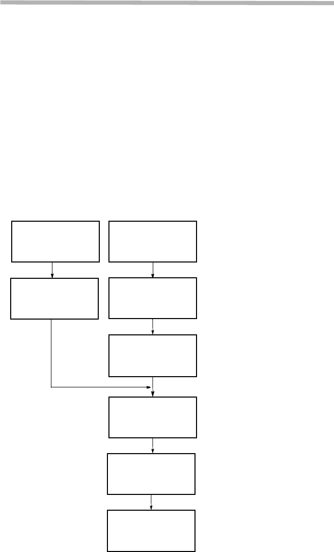
The standard installation is summarized in this section. Included herein is
information on typical installation work flow and guides for IDU
installation, ODU installation, Antenna (ANT) installation, waveguide
connection and coaxial cable connections. The installation flow diagram
is shown below.
This product is a part of radio link system, and is intended to be connected
with a external antenna.
This product will be installed and operated by professional.
After installation, the professional person shall make sure that the system
shall comply with the relevant limits for general public exposure specified
as basic restrictions or reference levels in the council Recommendation
1999/519/EC.
Unpacking of IDU
(see para 2.2) Unpacking of ODU
(see para 2.2)
ODU Mounting
(see para 2.6)
IDU Mounting
(see para 2.3)
Feeder Connection
(see para 2.7)
Frame Grounding
(see para 2.8)
Cable Termination
(see para 2.10)
Waterproof
Protection
(see para 2.9)
Fig. 2-1 Typical Installation Flow Diagram