NEC of America 58155 NEC NLite E 155 MB 5.8 GHz Digital Microwave Radio User Manual Part 2
NEC Corporation of America NEC NLite E 155 MB 5.8 GHz Digital Microwave Radio Part 2
Contents
- 1. User Manual Part 1
- 2. User Manual Part 2
- 3. User Manual Part 3
- 4. User Manual Part 4
- 5. User Manual Part 5
User Manual Part 2

INSTALLATION ROI-S05750
2-2
2.1 Packages
Each unpacked component of the [ ] GHz [ ] MB digital radio system
must be checked as shown below.
CONTENS LIST DRAWING NO.
IDU and ODU Fig. 2-2
Mounting Bracket Fig. 2-3
Installation Kit Fig. 2-4 and Fig. 2-5
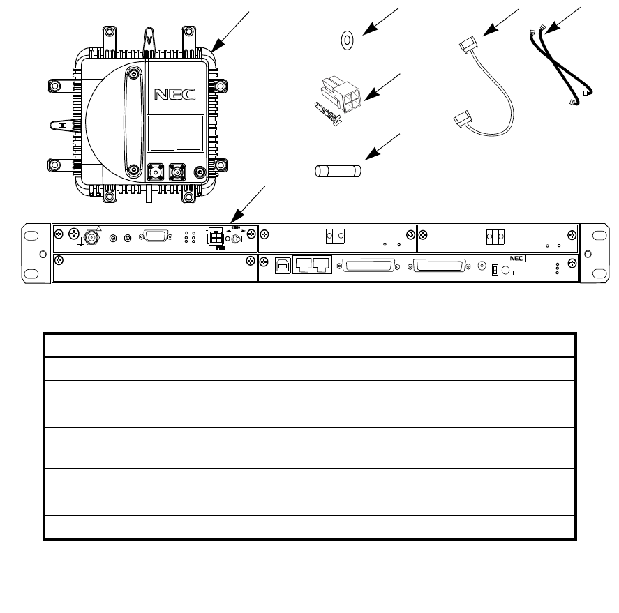
Note: *1 One more ODU and MODEM module are provided for HS/Twinpath configuration.
*2 One spare fuse is provided in the MODEM module.
No. DESCRIPTION
1 TRP-( )G-1B / TRP-52G-5A (ODU)
2 MDP-150MB-1AA (IDU)
3 O-Ring (Attached to the waveguide type ODU)
4Power Connector (Molex Housing M5557-4R (x1ea) and Socket Contact
(5556TL (x4 each))
5 Cylindrical Fuse ((RKS-F91000-0107) (6.3A) (x1ea) *2)
6 XPIC CTRL Cable (×1) (apply for XPIC configuration only)
7 X-IF Coaxial Cable (×2) (apply for XPIC configuration only)
3
1
2
4
5
67
FG
IFL
MON
RX LEV
(*1)
NLite E
SELV
!
AUX/ALM
NMS NE
ALM
SC IN/OUT EOW
PROTECT
CALL MMC
MAINT
MEMORY
IDU
XIF IN XIF OUT
IF IN/OUT TX
RX
RESET
XPIC CTRL XPIC
PWR
ODU
MD/
CBL PWR
NLite E NEO
LCT
OC-3 IN
OC-3 OUT
PULL
ALM
OC-3 IN
OC-3 OUT
(Blank)
ONLINE
ONLINE
G
G
G
ROI-S05750 INSTALLATION
2-3
Fig. 2-2 Contents of Basic Unit Package
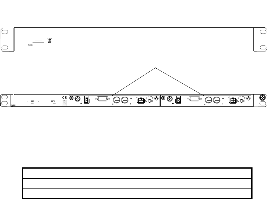
No. DESCRIPTION
1 H3042K I/O BOARD Bracket
2 NWA-011060-001 DC-DC CONV UNIT (see Fig. 2-7 for details)
1
H3042K I/O BOARD
SER No.
DATE
WEIGHT kg
MADE IN JAPAN
SELV
PWR PULL
PWR
ALM FUSE (250V/8AH)
−
43V
G
OUT
STD
G
SELV
PWR PULL
PWR
ALM FUSE (250V/8AH)
−
43V
G
OUT
STD
G
NWA-011060-001 DC-DC CONV UNIT
SER No. DATE ,
WEIGHT 2.5kg
MADE IN JAPAN
NEC Corporation
TOKYO JAPAN
1+0 System STD Input : 20 60V 3.4A 1.0A
Output :
−
43V 1.3A
1+1 System STD Input : 20 60V 1.3A
×
2
3.4A 1.0A
×
2 Output :
−
43V
2
INSTALLATION ROI-S05750
2-4
Fig. 2-3 Contents of Optional Unit Package
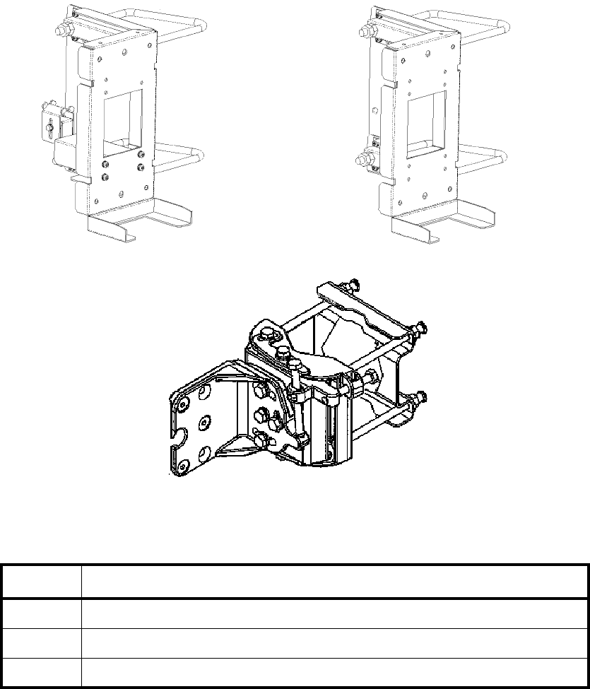
(Supplied with antenna)
3
12
No. DESCRIPTION
1Pole Mounting Bracket for Coaxial Cable Connection Type (6/7/8 GHz)
2Pole Mounting Bracket for Wave Guide connection Type
3Pole Mounting Bracket for Antenna direct Mounting Type
ROI-S05750 INSTALLATION
2-5
Fig. 2-4 Pole Mounting Bracket
INSTALLATION ROI-S05750
2-6
NLite E
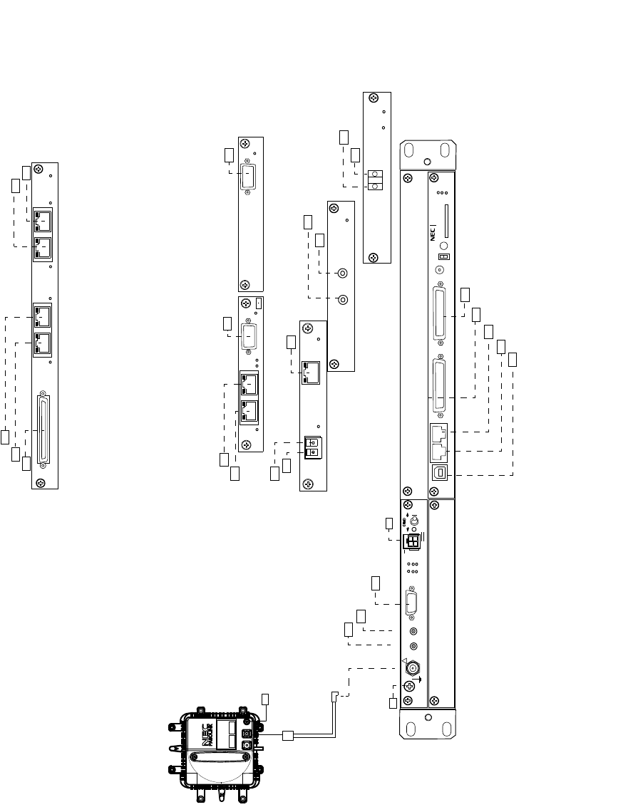
Fig. 2-5 Installation Kit Packing List of IDU and ODU for 1+0 System
IDU
No.1 ODU
SELV
!
AUX/ALM
LCT NMS NE SC IN/OUT EOW
PROTECT
CALL MMC
MAINT
MEMORY
IDU
XIF IN XIF OUT
IF IN/OUT TX
RX
RESET
XPIC CTRL XPIC
PWR
ODU
MD/
CBL PWR
NLite E
PULL
MOLEX CONNECTOR/ (FEMALE)
LUG D-SUB Accessory cable/(MALE)
D-SUB CONNECTOR/(MALE)
D-SUB CONNECTOR/(MALE)
MODULAR CONNECTOR/(MALE)
MODULAR CONNECTOR/(MALE)
USB CONNECTOR/(MALE)
FG
IFL
MON
RX LEV
N-P CONNECTOR
(MALE)
TNC-P CONNECTOR (MALE)
OC-3 IN OC-3 OUT
ALM
OC-3 INTFC
IEC 169-13 (P) CONNECTOR
IEC 169-13 (P) CONNECTOR
ALM
OC-3 IN
OC-3 OUT ONLINE
OC-3 INTFC
(150M)
(OPT)
LC (P) CONNECTOR
LC (P) CONNECTOR
LUG
(BLANK)
G
G
G
Note: It is recommended that TNC (Male) L-angle connector for the 8D-FB IF cable is used to
connect it to the IDU. When the N (Male) straight connector is attached to the 5D-FB or 10D-
FB IF cable, use of the TNC (Male) - N (Female) (NJ-TNCP-LA) L-angle adapter is needed.
LAN INTFC
(SONE
ALM
WS IN/OUT
100M PORT 1 PORT 2 100M
WS ALM
WS IN/OUT
100M PORT 3 PORT4 100M
100M PORT 1 PORT 2 100M
ALM
2M IN/OUT
ALM
OUT
1000BASE-SX
PORT
IN
LAN INTFC
4P LAN INTFC
LC (P) CONNECTOR
LC (P) CONNECTOR MODULAR CONNECTOR/(MALE)
1053J8A (P) Accessory cable
1053J8A (P) Accessory cable
D-SUB CONNECTOR/(MALE) D-SUB CONNECTOR/(MALE)
D-SUB CONNECTOR/(MALE)
MODULAR CONNECTOR/(MALE)
MODULAR CONNECTOR/(MALE)
MODULAR CONNECTOR/(MALE)
MODULAR CONNECTOR/(MALE)
MODULAR CONNECTOR/(MALE)
MODULAR CONNECTOR/(MALE)
GbE INTFC
(SONET)
(SONET)
Note: The LAN/WS INTFC which is put a [M.S] label may be installed into either Slot1 or Slot2 on
the IDU in the SONET system.
M S
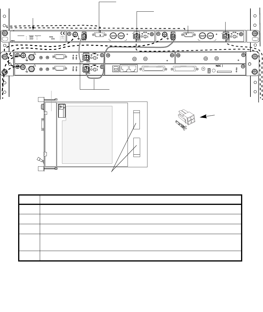
Note: *1 One more ODU and MODEM module are provided for HS/Twinpath configuration.
*2 Two spare fuses are provided in the DC-DC CONV module.
No. DESCRIPTION
1 NWA-011060-001 DC-DC CONV UNIT
2 H3040 DC-DC CONV
3 Power Cable (NWM-005773-001, attached to the DC-DC CONV)
4Power Connector (Molex Housing M5557-4R (x1ea) and Socket Contact
(5556TL (x4 each))
5 Cylindrical Fuse ((CBE-006255-001) (8A) (x2 ea) *2)
SELV
PWR PULL
PWR
ALM FUSE (250V/8AH)
−
43V
G
OUT
STD
G
SELV
PWR PULL
PWR
ALM FUSE (250V/8AH)
−
43V
G
OUT
STD
G
NWA-011060-001 DC-DC CONV UNIT
SER No. DATE ,
WEIGHT 2.5kg
MADE IN JAPAN
NEC Corporation
TOKYO JAPAN
1+0 System STD Input : 20 60V 3.4A 1.0A
Output :
−
43V 1.3A
1+1 System STD Input : 20 60V 1.3A
×
2
3.4A 1.0A
×
2 Output :
−
43V
SELV
!
AUX/ALM
LCT NMS NE SC IN/OUT EOW
PROTECT
CALL MMC
MAINT
MEMORY
IDU
XIF IN XIF OUT
IF IN/OUT TX
RX
RESET
XPIC CTRL XPIC
PWR
ODU
MD/
CBL PWR
NLite E
PULL
G
G
G
OC-3 IN OC-3 OUT
ALM
SELV
!
XIF IN XIF OUT
IF IN/OUT TX
RX
RESET
XPIC CTRL XPIC
PWR
ODU
MD/
CBL PWR
PULL
G
OC-3 IN OC-3 OUT
ALM
MOLEX CONNECTOR/ (FEMALE)
MOLEX CONNECTOR/ (FEMALE)
D-SUB CONNECTOR/ (FEMALE)
D-SUB CONNECTOR/ (FEMALE)
DC-DC CONV UNIT
(Optional)
4
5
1
3
RESERVE RESERVE
CAUTION
HOT SURFACE
Avoid contact.
!
2
ROI-S05750 INSTALLATION
2-7
Fig. 2-6 Installation Kit Packing List of DC-DC CONV UNIT for 1+1 System
INSTALLATION ROI-S05750
2-8
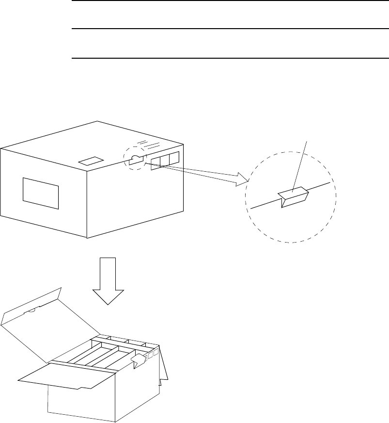
2.2 Unpacking of IDU and ODU
The unpacking procedures for the IDU and ODU are shown in following
chart.
• IDU : Chart 2-1
• ODU : Chart 2-2
Note: When conveying the IDU or ODU to another place, the original
packing should be used to avoid damage.
Chart 2-1 Unpacking Method for IDU
Step Procedure
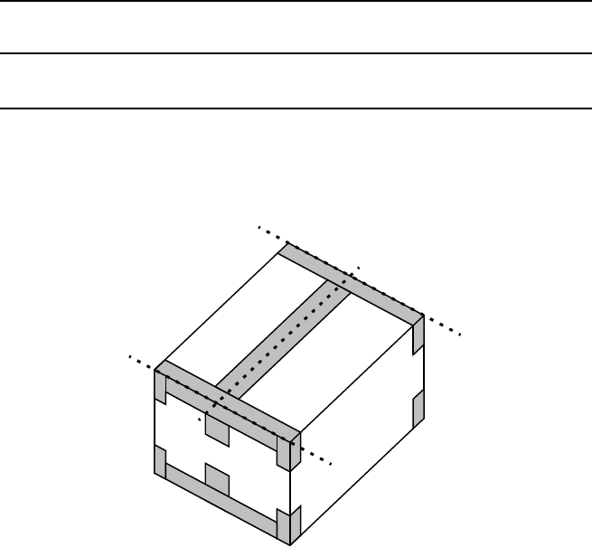
1 Cut the p.p. tape at top of the carton (1 to 3). Then open the
carton,
21
3
ROI-S05750 INSTALLATION
2-9
Chart 2-1 (Cont’d)
Step Procedure
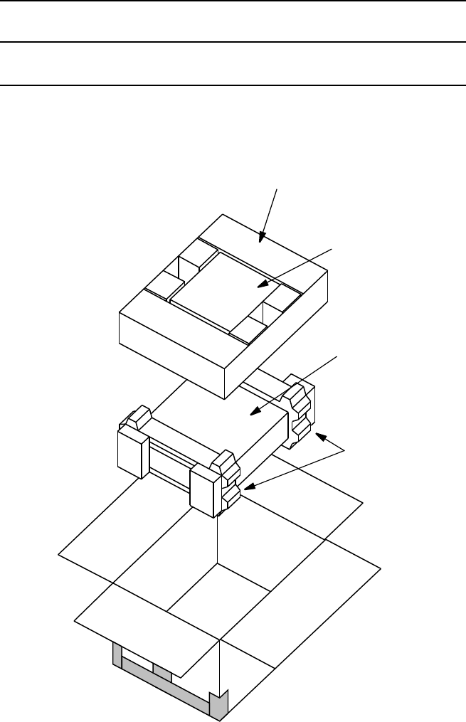
2 Take out the accessories, IDU carton and cushioning materials,
CUSHIONING
MATERIAL
CARTON
(ACCESSORIES)
CARTON
(IDU)
CUSHIONING
MATERIAL
(IDU)
INSTALLATION ROI-S05750
2-10
Chart 2-1 (Cont’d)
Step Procedure
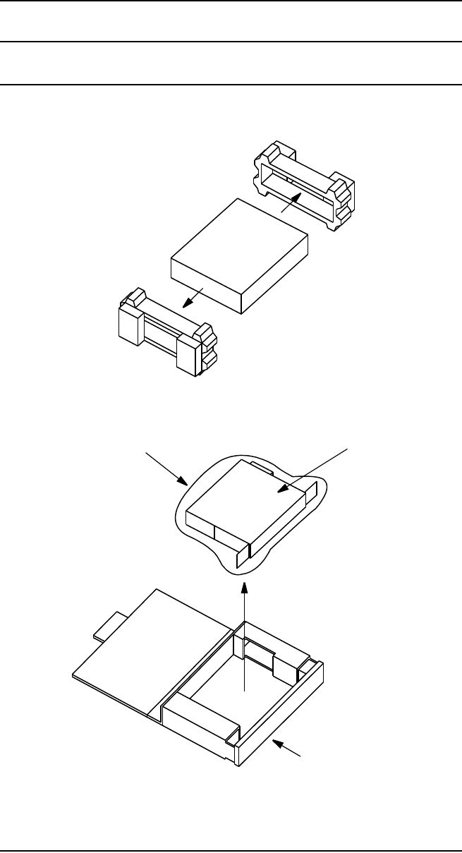
3 Remove the cushioning materials from the carton (IDU),
4 Take out the IDU wrapped with antistatic bag from the carton,
ANTISTATIC BAG IDU
CARTON (IDU)
5 Take out the IDU from the antistatic bag,
6 Inspect the IDU.
ROI-S05750 INSTALLATION
2-11
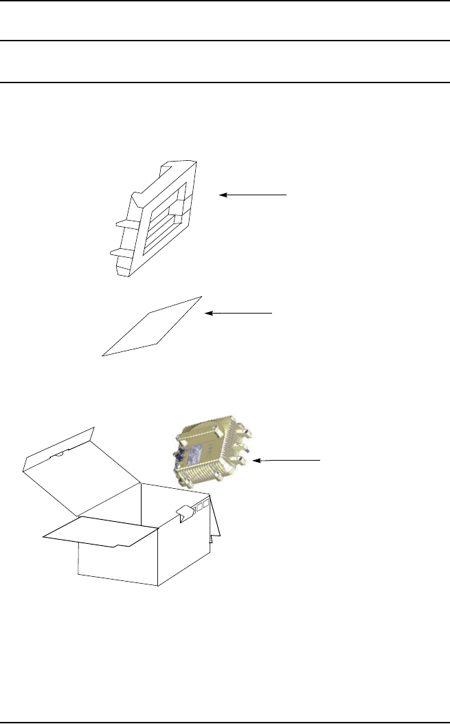
Chart 2-2 Unpacking Method for ODU
Step Procedure
1 Take off the hook of a cover as shown below. Then, open the
top cover,
HOOK
INSTALLATION ROI-S05750
2-12
Chart 2-2 (Cont’d)
Step Procedure
2 Take out cushioning material, buffer material and poly sheet,
POLY SHEET
ODU
TOP PAD
3 Take out the ODU from carton,
4 Inspect the ODU.
ROI-S05750 INSTALLATION
2-13
2.3 IDU Mounting
The installation procedure for the IDU explains in Chart 2-3. The IDU
should be installed in the radio station.
Chart 2-3 Mounting Methods of the IDU
Step Procedure
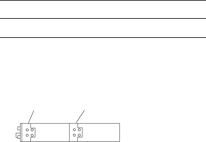
1 Change the two brackets to desired position on the IDU, if
necessary,
FRONT
POSITION CENTER
POSITION
SIDE VIEW
1+0/1+1 SYSTEM
INSTALLATION ROI-S05750
2-14
Chart 2-3 (Cont’d)
Step Procedure
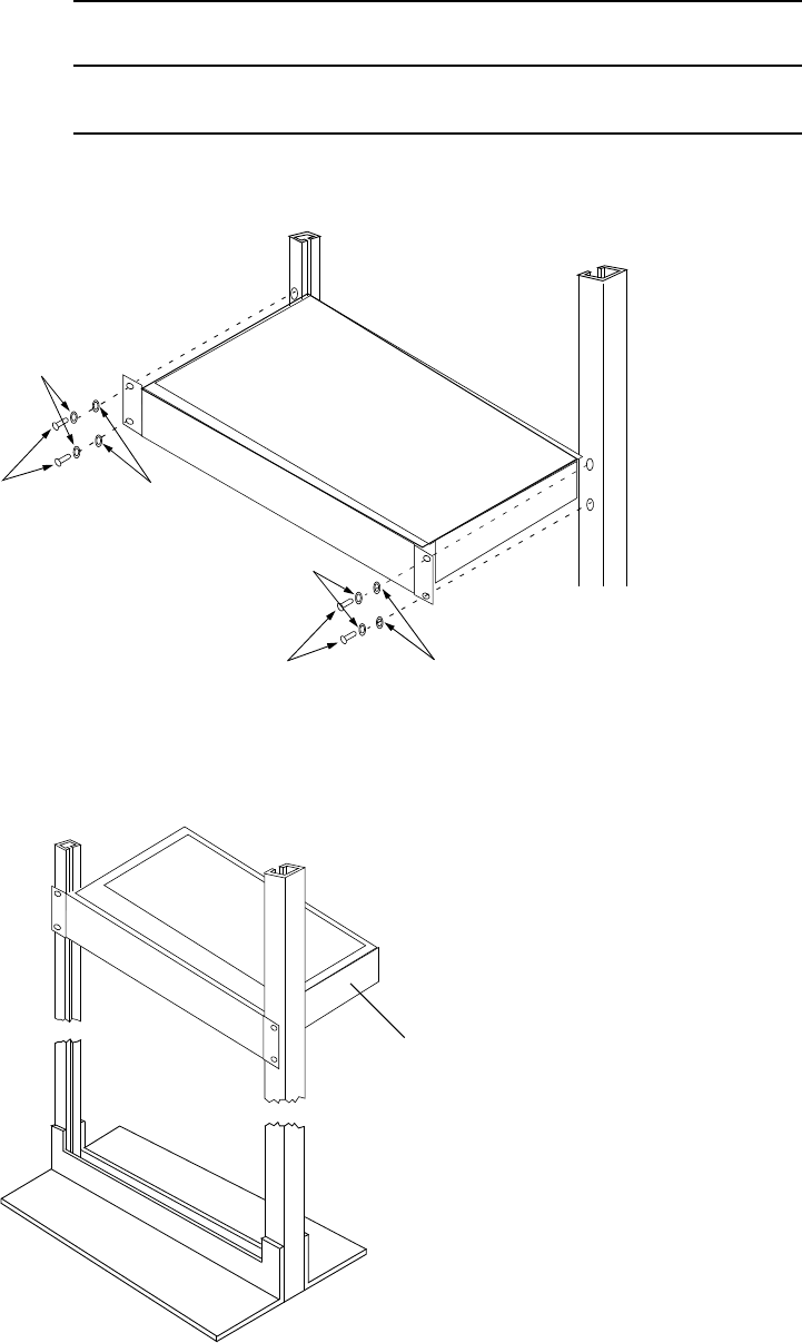
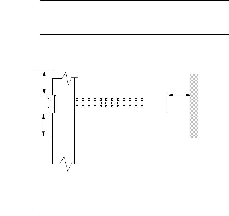
2 Align the IDU to the mounting position on the 19-inch rack,
SCREW FLAT WASHER
SCREW FLAT WASHER
SPRING WASHER
SPRING WASHER
3 Fix each side of the IDU to the 19-inch rack with the two
screws,
IDU
ROI-S05750 INSTALLATION
2-15
Chart 2-3 (Cont’d)
Step Procedure
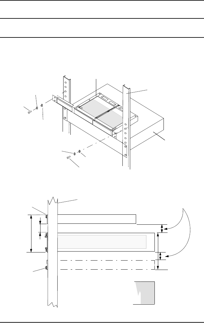
4 To mount the IDU in a 19-inch rack, take a space more than 200
mm to the rear section and space for one unit to the top and
bottom.
At least
one rack unit *
At least
one rack unit *
More than
200 mm *
Note: * Normal setting for free space. When free space is closed within
one rack unit, keep the environment temperature is lower than
+40
°
C.
WALL
This Page Not Used
INSTALLATION ROI-S05750
2-16
2.4 DC-DC CONV UNIT Mounting (Optional)
The installation procedure for the DC-DC CONV UNIT (optional)
explains in Chart 2-5. The DC-DC CONV UNIT(optional) should be
installed in the radio station.
Chart 2-4 Mounting Methods of the DC-DC CONV UNIT
Step Procedure
1 Fix the DC-DC CONV UNIT to the 19-inch rack using the two
screws.
At least
0.5 rack unit *
IDU
DC-DC CONV UNIT
SCREW
SPRING
WASHER
SCREW
FLAT
SPRING
WASHER
WASHER
2U
0.5U
IDU
DC-DC CONV UNIT
DC-DC CONV UNIT
RACK
upper
screw hole
lower
screw hole
Note: * Space 0.5 rack unit in the upper or lower DC-DC CONV
UNIT.
2U
FLAT
WASHER
DC-DC CONV UNIT
RACK

INSTALLATION ROI-S05750
2-22
2.6 NLite E SONET OC-3ODU Mounting
The procedures for mounting and demounting the ODU are described
here. There are two types of mounting for the antenna direct mounting
type and waveguide connecting type. The ODU should be installed in the
radio station. The tools for installation are listed in Table 2-1.
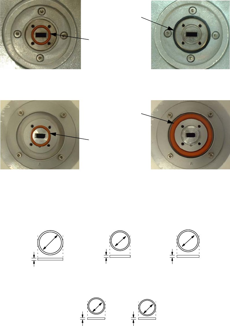
Caution 1. How to use small and large O-rings are shown in
following table. Two (small and large) O-rings are
attached in 18 to 38 GHz band Andrew/RFS direct mount
antenna. 11/13/15 GHz band antenna does not have small
O-ring (Small O-ring is not used for Andrew/RFS direct
mount antenna). If the small O-ring is used for ODU
direct mount installation, a gap may occur between ODU
and antenna for RF interface. Therefore it may happen
transmit or receive level down.
Caution 2. Do not apply silicon grease at O-ring.
Notes:11/13/15 GHz antenna for direct mount is not possible to connect
the ordinary waveguide flanges.
Table 2-1 Tools
TOOLS
Wrench or Monkey wrench
Screwdriver
Torque Wrench
SYSTEM ATTACHENENT
POSITION OF
O-RING (BETWEEN:)
O-RING REMARKS
SMALL SIZE LARGE SIZE
1+0
ANT ⎯ ODU Not used Used Antenna direct mounting
ANT ⎯ WG/ODU
(18-38 GHz BAND) Used Not used Waveguide connection
1+1
ANT ⎯ HYB Not used Used Antenna direct mounting
ANT ⎯ WG/HYB
(18-38 GHz BAND) Used Not used Waveguide connection
ROI-S05750 INSTALLATION
2-23
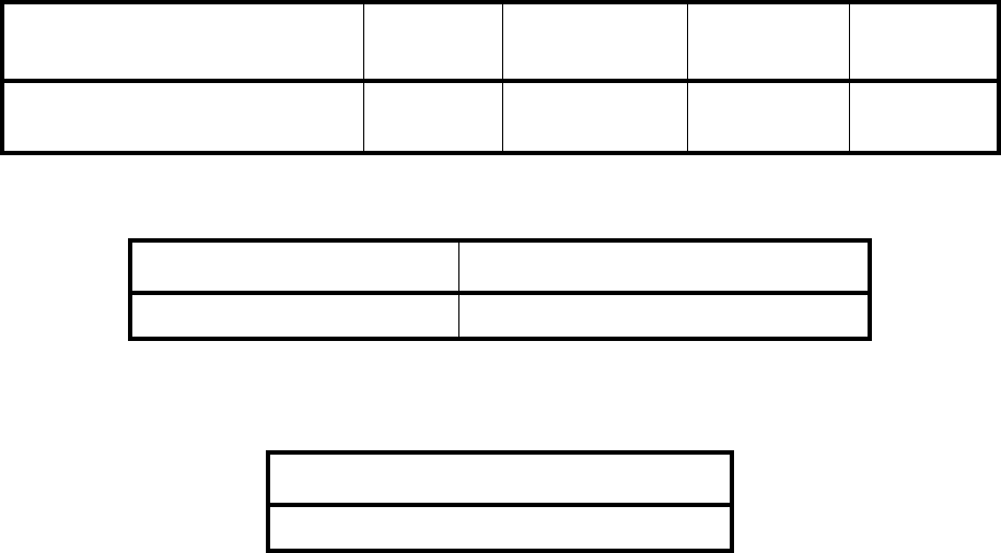
Notes: 1. Do not use both small O-ring and large O-ring
simultaneously.
2. O-ring size is different with frequency band as follows:
POSITION
OF LARGE
SIZE O-RING
POSITION
OF SMALL
SIZE O-RING
FOR WAVEGUIDE CONNECTION FOR ANTENNA DIRECT MOUNTING
ANDREW ANTENNA
POSITION
OF LARGE
SIZE O-RING
POSITION
OF SMALL
SIZE O-RING
FOR WAVEGUIDE CONNECTION FOR ANTENNA DIRECT MOUNTING
RFS ANTENNA
32mm
35mm
LARGE SIZE O-RING FOR ANTENNA DIRECT MOUNTING
26 GHz BAND
40mm
10-11 GHz BAND 13-23 GHz BAND
4 mm
4 mm
4 mm
18/23 GHz BAND 32/38 GHz BAND
15.6mm
SMALL SIZE O-RING FOR WAVEGUIDE CONNECTION
10.8mm
1.8 mm
1.8 mm
INSTALLATION ROI-S05750
2-24
2.6.1 Mounting
The method of mounting is listed in Table 2-2 to Table 2-4.
Table 2-2 Antenna Direct Mounting
Change of Polarization ODU/
Bracket HYB TX SPAN
ATT OMT
Chart 2-6
ANT/ODU/HYB/TX SPAN ATT Chart 2-7 Chart 2-8 Chart 2-9 Chart 2-11
Table 2-3 Waveguide Connection
Using 1+1 HYB 1+0 or Connecting Two Antennas
Chart 2-10 Chart 2-12
Table 2-4 Coaxial Cable Connection
With/Without HYB
Chart 2-13
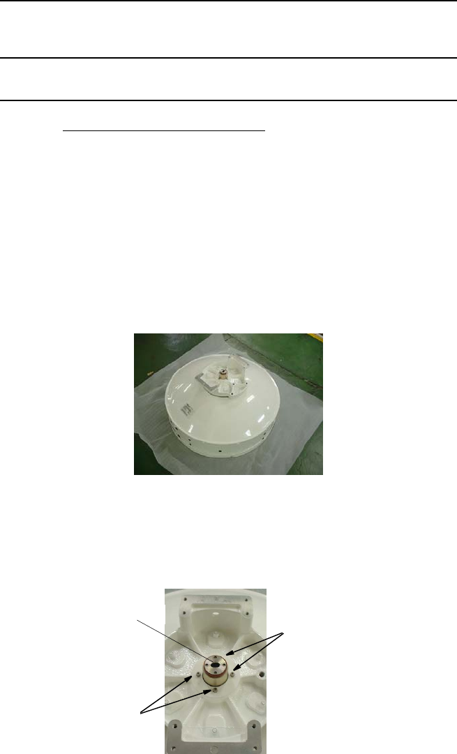
ROI-S05750 INSTALLATION
2-25
Chart 2-6 Change of Polarization (Antenna Direct
Mounting)
Step Procedure
CHANGE OF POLARIZATION
ODU DIRECT MOUNTING TYPE ANTENNA
(Example (ANDREW) 1/2)
Note: The details are referred to the installation manual which
is attached to the antenna. The installation or removal of
the antenna requires qualified experienced personnel.
Note: The antenna is set to V-polarization when shipped from
the factory.
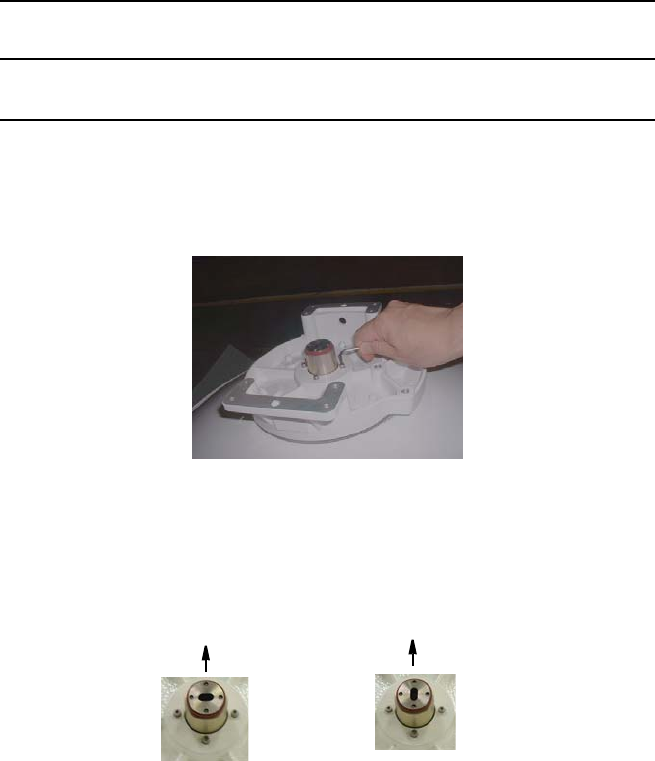
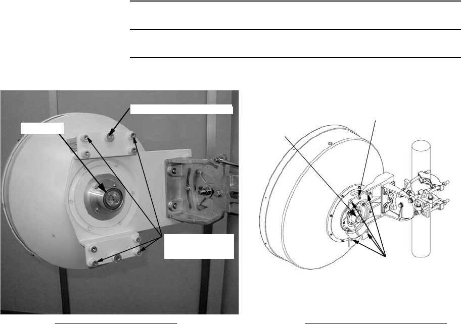
1 Keep the antenna stand horizontally,
2 If you change to H polarization, loosen the four screws with the
Allen key wrench and then rotate the Transition hub of feed,
keeping the antenna stand horizontal.
Transition hub
2 SCREWS
2 SCREWS
INSTALLATION ROI-S05750
2-26
Chart 2-6 (Cont’d)
Step Procedure
Note: Do not remove the screw complete from the screw hole.
Hold the feed horn with hand.
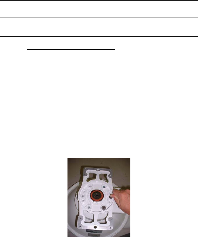
3 Holding the feed with hand, rotate the feed 90 degrees,
Check that the aperture part of the Transition hub is rotated 90
degrees, then fix it with the screws that were loosened in step 2,
4 Check that the aperture part of the Transition hub is rotated 90
degrees, then fix it with the screws that were loosened in step 2
Note: When a large and a small gasket are included in the
antenna package. Please use the large one (The small
gasket is not used in antenna mount)
Polarization
V
Polarization
H
Top Top
ROI-S05750 INSTALLATION
2-27
Chart 2-6 (Cont’d)
Step Procedure
CHANGE OF POLARIZATION
ODU DIRECT MOUNTING TYPE ANTENNA
(Example (ANDREW) 2/2)
Note: The details are referred to the installation manual which
is attached to the antenna. The installation or removal of
the antenna requires qualified experienced personnel.
Note: The antenna is set to V-polarization when shipped from
the factory.
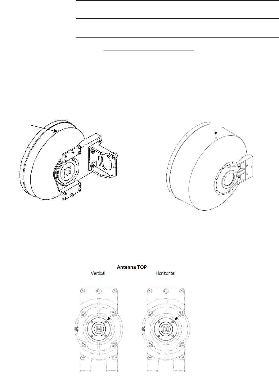
1. Keep the antenna stand horizontally,
2. Loosen six screws with Allen wrench until transition can rotate
freely,
Note: Do not remove the screw complete from the screw hole.
Note: Because of the screwtight is applied, the strength to
loosen screw is necessary.
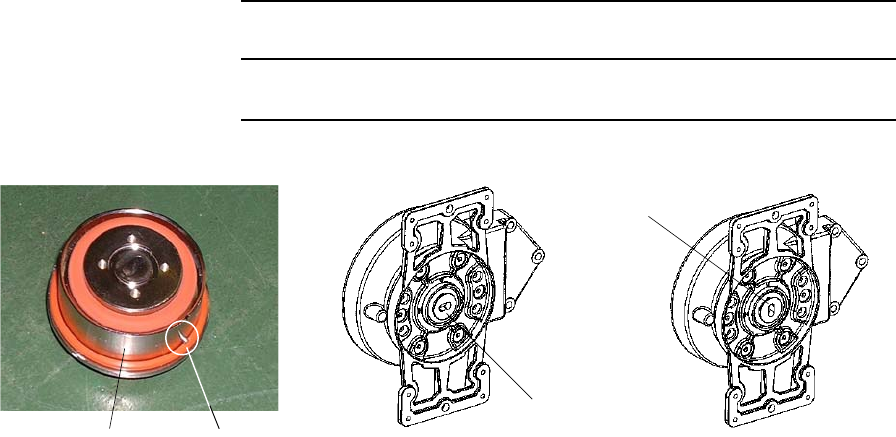
3 Rotate the transition hub 90 degrees until timing pin locates in
timing concavity,
INSTALLATION ROI-S05750
2-28
Chart 2-6 (Cont’d)
Step Procedure
Tighten six screws when transition hub is located. (Tightening
torque is 5.0 N·m ± 10%.)
Vertical Polarized Application Horizontally Polarized Application
Transition hub
Transition hub
Timing PinTransition Hub
ROI-S05750 INSTALLATION
2-29
Chart 2-6 (Cont’d)
Step Procedure
CHANGE OF POLARIZATION
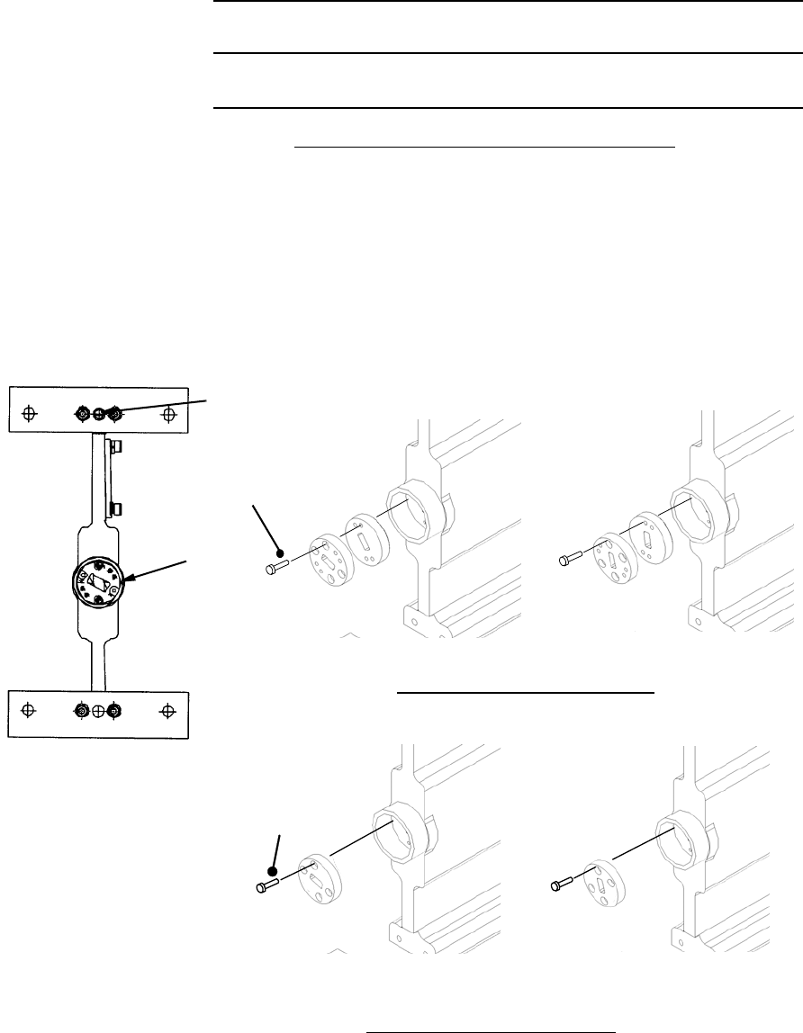
ODU DIRECT MOUNTING TYPE ANTENNA
(Example (RFS))
Note: The details are referred to the installation manual which
is attached to the antenna. The installation or removal of
the antenna requires qualified experienced personnel.
Note: The antenna is set to V-polarization when shipped from
the factory.
RFS SB1
1. Unscrew the 4 screws M3 at the refined
steel ring,
2. Hold the feed tightly at the waveguide,
3. Rotate carefully the feed 90 degrees,
4. Mount the feed to the refined steel ring
and lock the 4 screws M3.
1. Loosen the 4 screws M3,
2. Hold the feed tightly at the waveguide,
3. Rotate the casting plate carefully the
feed 90 degrees,
4. Lock the 4 screws M3.
RFS C-Mount
Drain Plug
Drain Plug
4 screws (M3)
Polarization V Polarization H
INSTALLATION ROI-S05750
2-30
Chart 2-6 (Cont’d)
Step Procedure
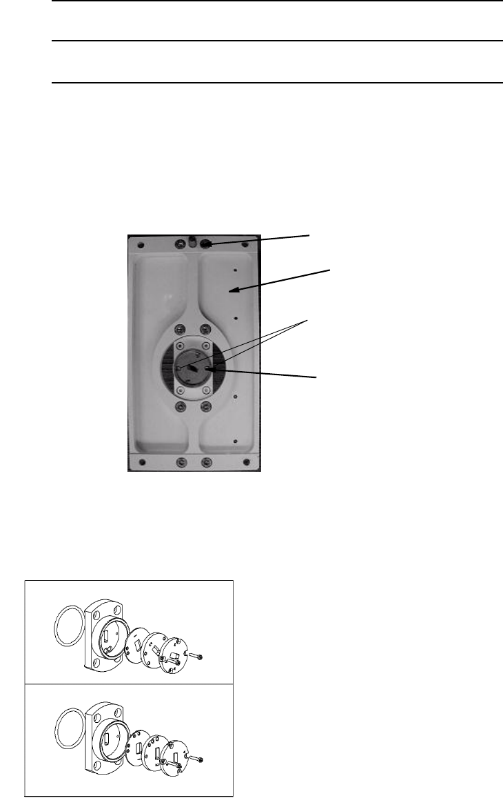
CHANGE OF POLARIZATION OF THE HYB
NEC HYBRID
Note:The hybrid is set to V-polarization when shipped from the factory.
1 If you change the polarization from V to H, loosen two screws,
rotate the transition hub and put it to the HYB.
1Note: There are two types NEC HYBRID. One uses two pieces
transition hubs and another uses one piece.
2 Then fix it with the two screws that were loosened in step 1.
TRANSITION
HUB
V POLARIZATION
GUIDE PIN
HYB
V POLARIZATION H POLARIZATION
Two Pieces Transition Hub Type
H POLARIZATION
V POLARIZATION
One Piece Transition Hub Type
(Only for 13/15/18/23 GHz HYBRID)
M2.6(2ea)
Cr oss- Recessed
Head Machine Screw
Cross-Recessed
Head Machine Screw
M2.6 (2ea)
ROI-S05750 INSTALLATION
2-31
Chart 2-6 (Cont’d)
Step Procedure
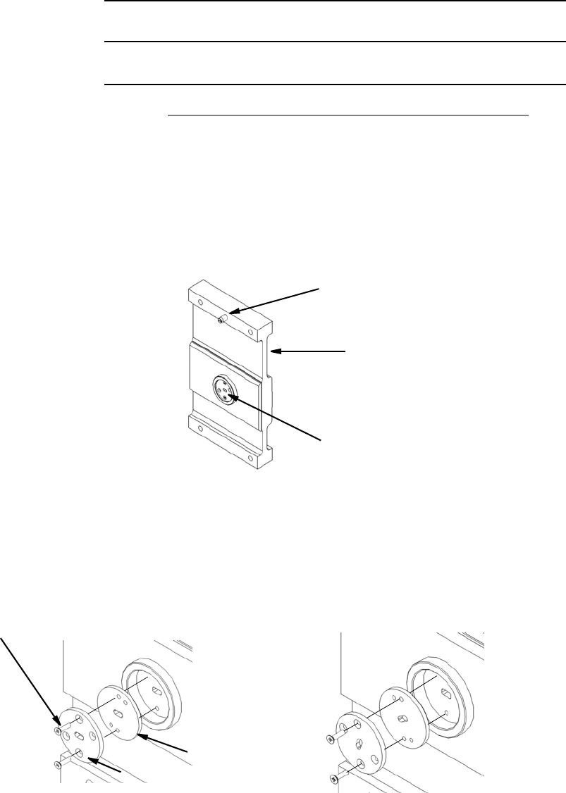
Quasar HYBRID
Note: The hybrid is set to V-polarization when shipped from the factory.
1 If you change to H polarization, loosen two screws, rotate the
antenna connection unit and put the HYB horizontally.
2 Check that the aperture of the connection unit is rotated as
shown below, then fix it with the two screws that were loosened
in step 1.
HYB
ANTENNA
CONNECTION UNIT
V POLARIZAION
GUIDE PIN
SCREW
Quasar HYB
V POLARIZATION
H POLARIZATION
INSTALLATION ROI-S05750
2-32
Chart 2-6 (Cont’d)
Step Procedure
CHANGE OF POLARIZATION OF THE TX SPAN ATT
TX SPAN ATT
Note: The TX ATT is set to V-polarization when shipped from the
factory.
1 If you change to H polarization, loosen two screws, rotate the
antenna connection unit and put the TX ATT horizontally.
2 Check that aperture of the connection unit is rotated as shown
below, then fix it with the two screws that were loosened in
step 1.
TX ATT
ANTENNA
CONNECTION UNIT
V POLARIZATION
GUIDE PIN
Cross-Recessed
Head Machine Screw
M2.6(2ea)
Plate-2
Plate-1
H POLARIZATION
V POLARIZATION
38 GHz Band TX SPAN ATT Polarization Change
ROI-S05750 INSTALLATION
2-33
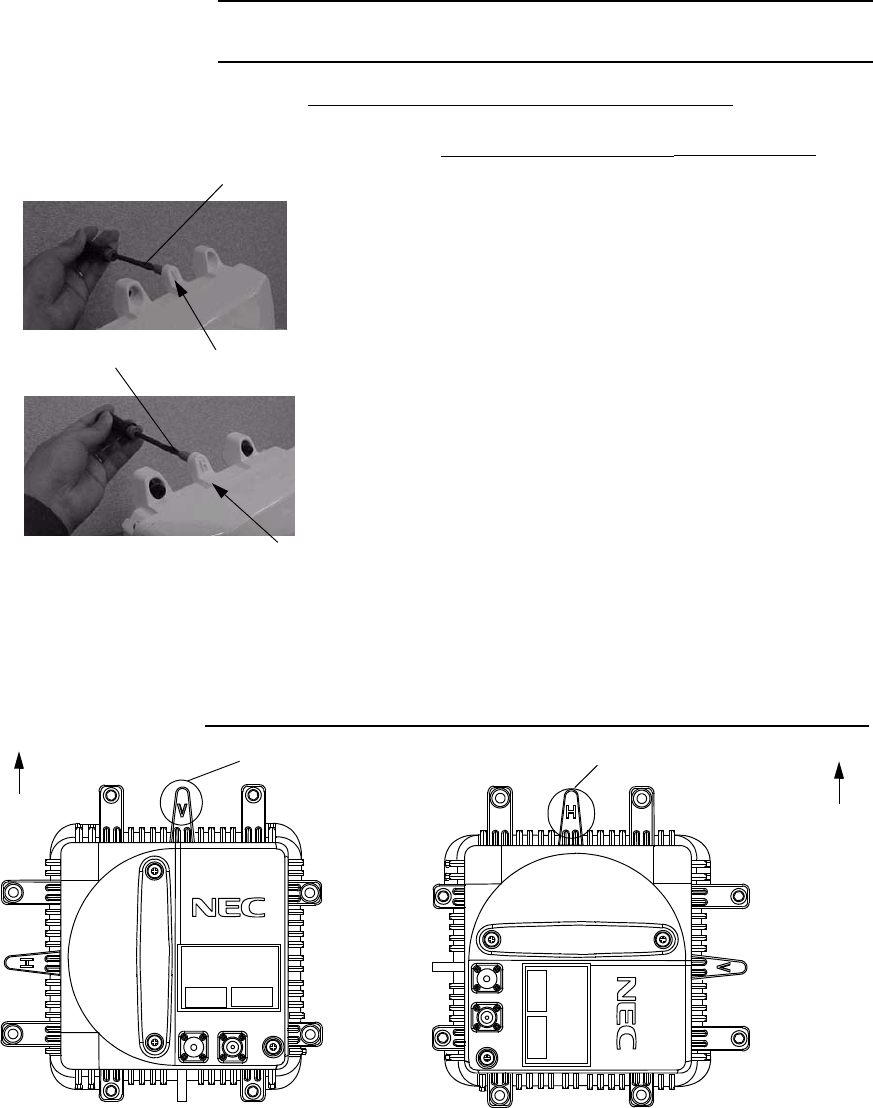
NLite EStep Procedure
CHANGE OF POLARIZATION OF THE ODU
1. When vertical polarization is required, rotate
the ODU so as to go up the plate marked V,
2. When horizontal polarization is required,
remove the guide pin fixed on the plate
marked with V,
3. Screw in the guide pin removed in step 2 to
the screw hole of the plate marked H,
4. Rotate the ODU so as to go up the plate
marked H,
PLATE MARKED WITH V
UP
V POLARIZATION
PLATE MARKED WITH H
UP
H POLARIZATION
FG
IFL
MON
RX LEV
FG
IFL
MON
RX LEV
GUIDE PIN
PLATE MARKED WITH V
GUIDE PIN
PLATE MARKED WITH H
Antenna Mounting ODU (11-38 GHz Band)
Note: When the ODU is mounted on to the NEC HYB, only V
polarization is applied.
Note: When the Waveguide or coaxial cable is connected between
the ODU and antenna, the ODU in V polarization for up
position is recommended for installation.
V/H Polarization Conversion
10-38 GHz ODU
NLite E
NLite E
INSTALLATION ROI-S05750
2-34
Chart 2-7 ODU Antenna Direct Mounting (11 - 38 GHz)
Step Procedure
ANTENNA DIRECT MOUNTING (10-38 GHz Band ODU)
Note: The details are referred to the installation manual which
is attached to the antenna.
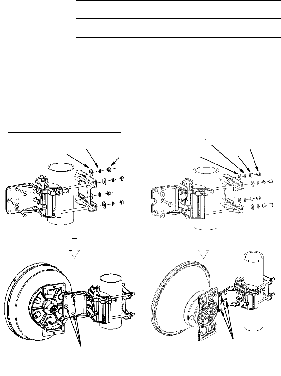
INSTALLATION OF BRACKET
1 Install the bracket to the antenna pole,
2 Mount antenna to the bracket,
ANDREW POLE MOUNT BRACKET
WASHER
LOCK WASHER
NUT*
WASHER
* Tightening torque of 22 N·m for M10.
Three(3) screws*
(Apply screwtight to threads
before fitting to antenna)
NUT*
PROTECTIVE
CAP
LOCK WASHER
Three(3) screws*
(Apply screwtight to threads
before fitting to antenna)
ROI-S05750 INSTALLATION
2-35
Chart 2-7 (Cont’d)
Step Procedure
ANTENNA DIRECT MOUNTING (10-38 GHz Band ODU)
RFS SB1 TYPE BRACKET

INSTALLATION ROI-S05750
2-36
Chart 2-7 (Cont’d)
Step Procedure
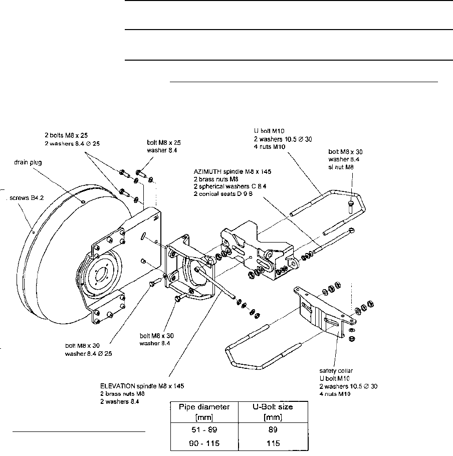
Note: The values in the following table are valid for screws and bolts which have been greased
according to the installation instructions.
Torques for RFS
Bolt M5 5Nm
M6 8Nm
M8 17 Nm
M10 35 Nm
M12 50 Nm
U-Bolt, V-Bolt (Pipe mount & safety collar) M10 20 Nm
Hexagonal brass nut of fine adjustment (Azimuth, Elevation) M8 5Nm
M10 10 Nm
M12 17 Nm
Hexagonal socket stainless steel screws (Feed systems install on aluminium mounting plate) M3 0.2 Nm
M4 0.4 Nm
Exceptions
Fixing screw of the azimuth fine adjustment spindle M8 x 30 8Nm
M12 x 55 17 Nm
Special application: NOT greased
Fixing screw of the plastic radome B4.2 3Nm
ROI-S05750 INSTALLATION
2-37
Chart 2-7 (Cont’d)
Step Procedure
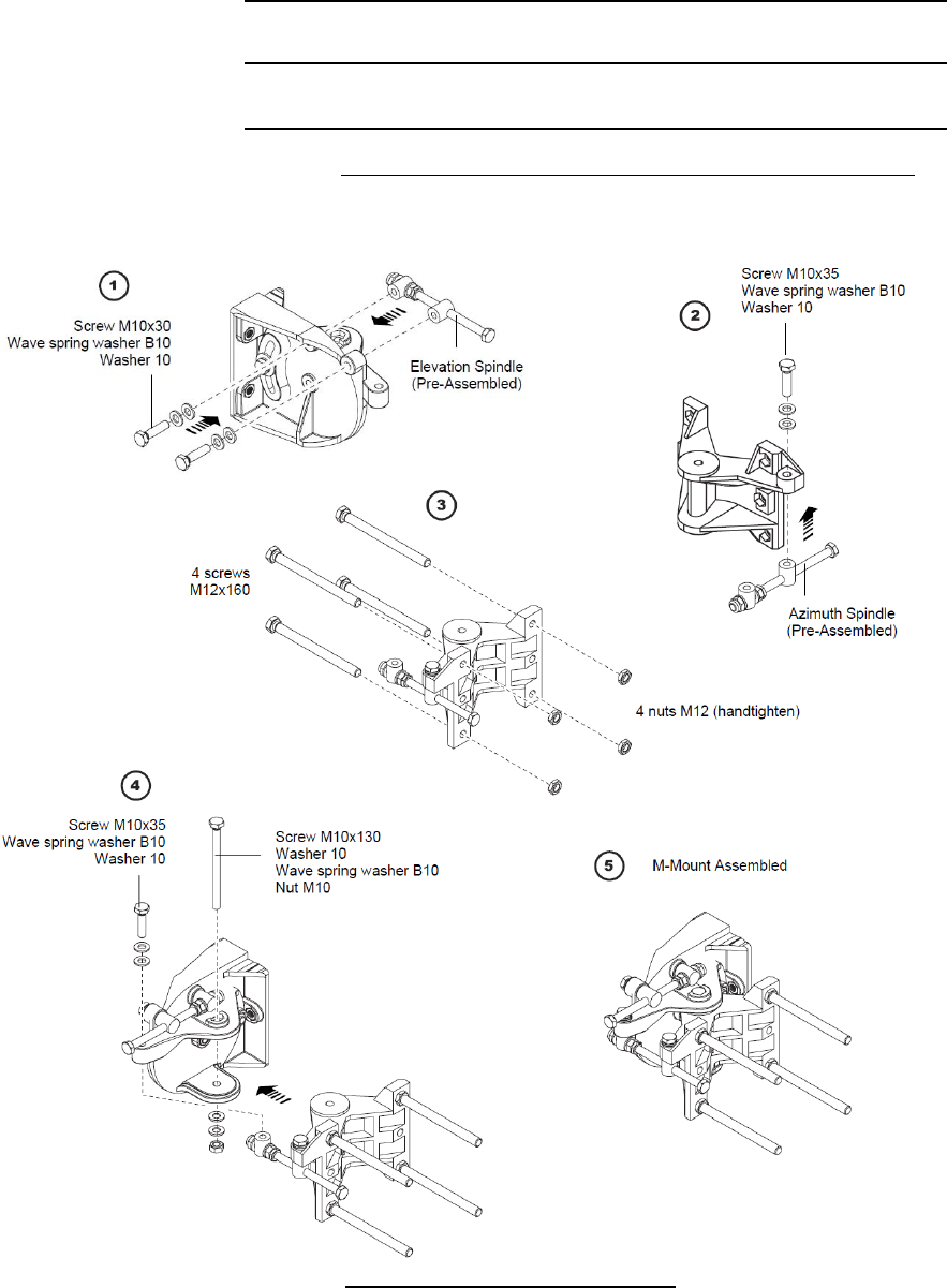
ANTENNA DIRECT MOUNTING (10-38 GHz Band ODU)
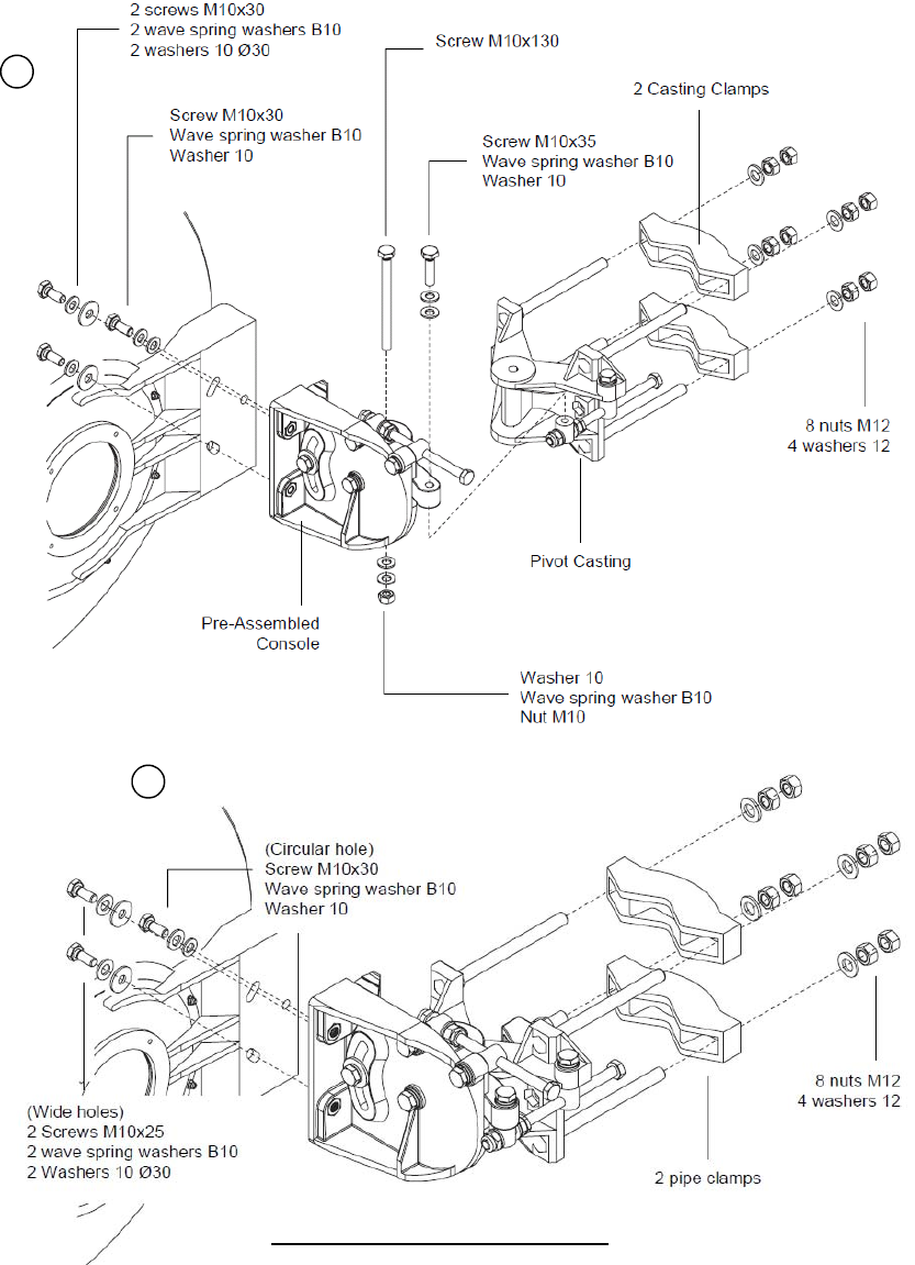
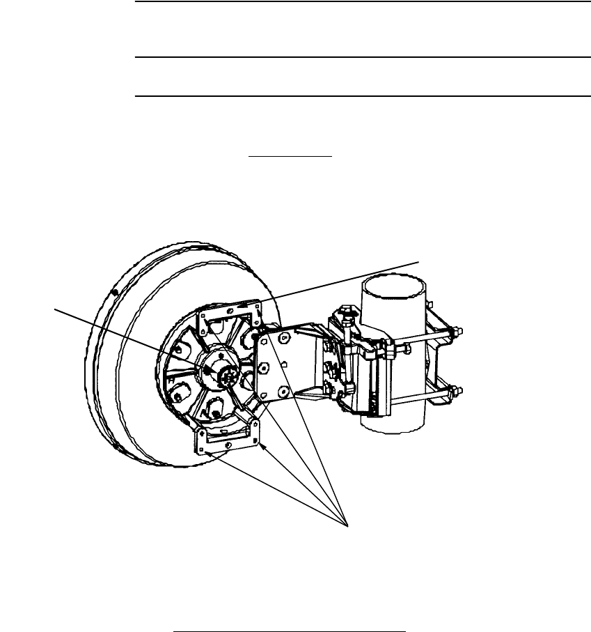
Pipe diameter: 48-114mm
RFS C-Mount TYPE BRACKET
MOUNT ASSEMBLY (RFS C-Mount Type)
INSTALLATION ROI-S05750
2-38
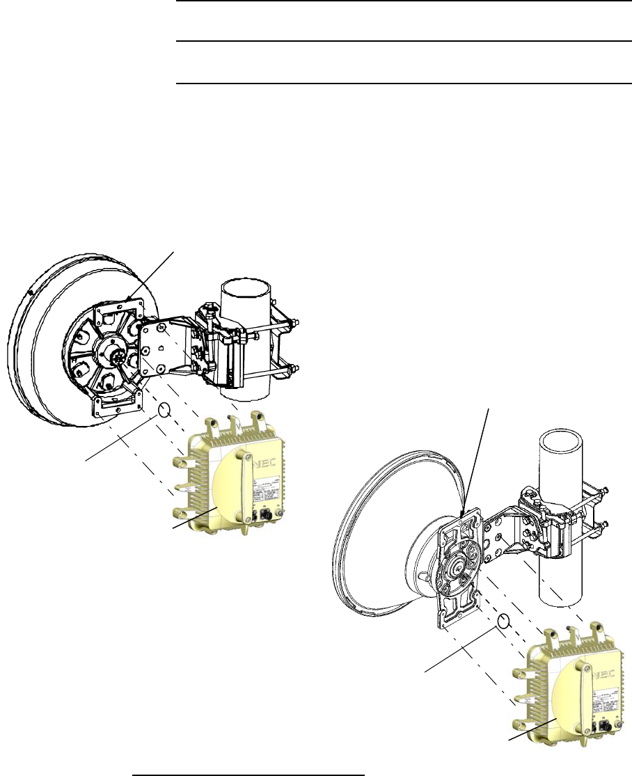
RFS C-Mount TYPE BRACKET
6
7
ROI-S05750 INSTALLATION
2-39
Chart 2-7 (Cont’d)
Step Procedure
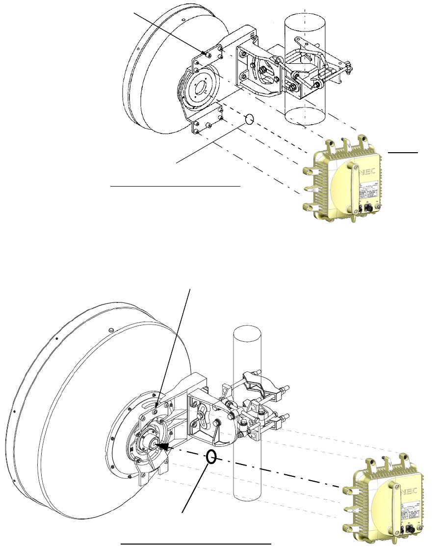
3 Fix the ODU to the bracket by tightening the M6 screws (four
locations),
Notes: 1. Figure shows V polarization.
2. Be careful not to damage the O-ring (Antenna).
3. The tightening torque is 4.0 N·m ± 10%.
O-RING
HOLE FOR GUIDE PIN
ODU
O-RING
HOLE FOR GUIDE PIN
ODU
ANDREW VHLP TYPE BRACKET
INSTALLATION ROI-S05750
2-40
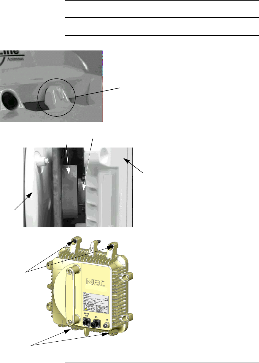
Notes: 1. Figure shows V polarization.
2. Be careful not to damage the O-ring (Antenna).
3. The tightening torque is 4.0 N·m ± 10%.
Notes: 1. Figure shows V polarization.
2. Be careful not to damage the O-ring (Antenna).
3. The tightening torque is 4.0 N·m ± 10%.
RFS SB1 TYPE BRACKET
O-RING
HOLE FOR GUIDE PIN
ODU
Note: Set the ODU to the bracket
after polarization of the ODU
is confirmed.
O Ring
RFS C-Mount TYPE BRACKET
HOLE FOR GUIDE PIN
ROI-S05750 INSTALLATION
2-41
Chart 2-7 (Cont’d)
Step Procedure
4. Insert guide pin on the hole of
bracket to set the position of screws,
GUIDE PIN
Caution: Align flanges on antenna
and ODU correctly, and fix
the ODU with four screws.
ODU
ODU FLANGE
ANTENNA FLANGE
ANTENNA
5. Fix the ODU to the bracket with four
screws.
Note: Torque: 4.0 N·m ± 10%
SCREWS
SCREWS
INSTALLATION ROI-S05750
2-42
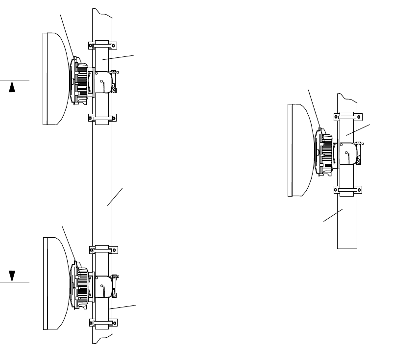
1+1 SD System
POLE
POLE
(S) MEMBER OF TOWER
1+0 System
MEMBER OF TOWER
POLE
Note: Antenna separation (S) is given by
path calcuration depending on the
system parameter.
No.1 ODU
No.2 ODU
ODU
ROI-S05750 INSTALLATION
2-43
Chart 2-8 NLite E SONET OC-3Antenna Direct Mounting
Using HYBRID
Step Procedure
ANDREW VHLP TYPE BRACKET
MOUNTING HOLE FOR
HYB
HOLE FOR GUIDE PIN
The tightening torque is 4.0 N·m ± 10%.
Be careful not to damage the O-ring(Antenna).
MOUNTING
Note: The details are referred to the installation
manual which is attached to the antenna.
O-RING
INSTALLATION ROI-S05750
2-44
Chart 2-8 (Cont’d)
Step Procedure
Note: The tightening torque is 4.0 N·m ± 10%.
Be careful not to damage the O-ring (Antenna).
HOLE FOR GUIDE PIN
O-RING
RFS SB1 TYPE BRACKET RFS C-Mount TYPE BRACKET
MOUNTING
HOLE FOR HYB
O-RING
HOLE FOR GUIDE PIN
MOUNTING HOLE
FOR HYB
ROI-S05750 INSTALLATION
2-45
Chart 2-8 (Cont’d)
Step Procedure
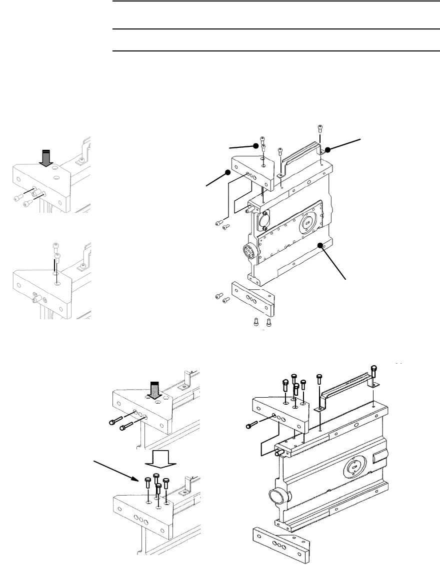
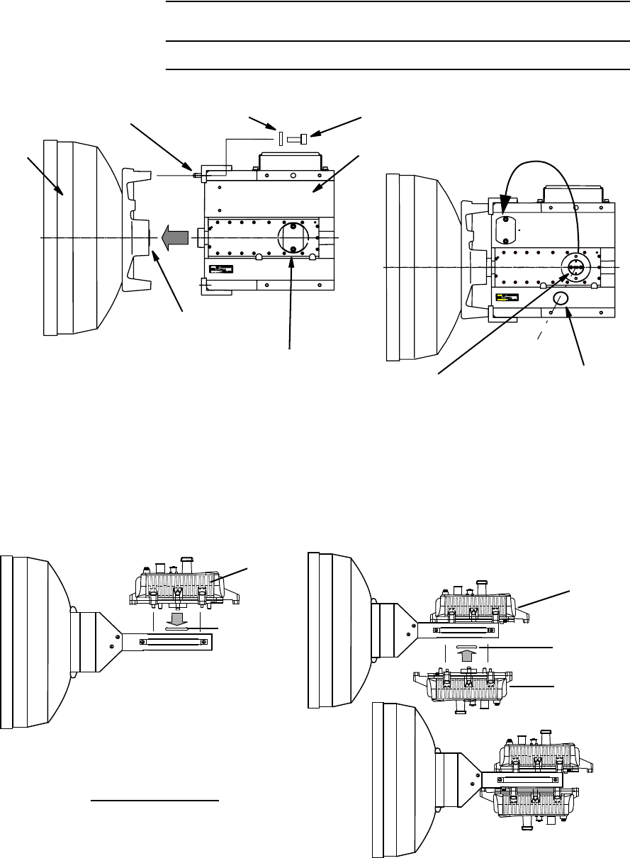
1 Fix the bracket and handle to the HYB used for 11-52 GHz
ODU.
2 Check the polarization and install the HYB to the antenna by
tightening the M6 screws (four locations).
M5 HEAD CAP SCREW
Note: Tightening torque is
3.0 N·m ± 10%.
PUSH
Note: Tightening torque is 3.0 N·m ± 10%.
M5X12(10ea)
Bracket
Hybrid
Handle
M5 HEAD CAP SCREW
For 2 screws Type Bracket
For 4 screws Type Bracket
INSTALLATION ROI-S05750
2-46
Chart 2-8 (Cont’d)
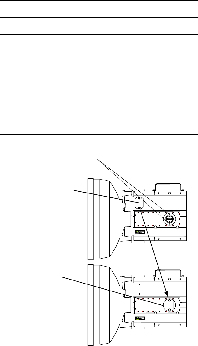
Step Procedure
3 Insert the O-rings to the two ODU ports of the HYB.
4 Install the two ODUs with hex screws (four locations) using the
Allen key wrench.
Note: Be careful not to damage the O-rings (Hybrid).
ANT
FLAT WASHER M6 SCREWGUIDE PIN
O-ring
SHORT PLATE
MOVE THE
SHORT PLATE
HYB
ODU PORT O-ring
Note: Tightening torque is
4.0 N·m ± 10%.
Note: Be careful not to damage the O-ring.
O-ring
ODU
O-ring
ODU
ODU
For 11-52 GHz ODU
Note: Tightening torque is 4.0 N·m ± 10%.
ROI-S05750 INSTALLATION
2-47
Chart 2-8 (Cont’d)
Step Procedure
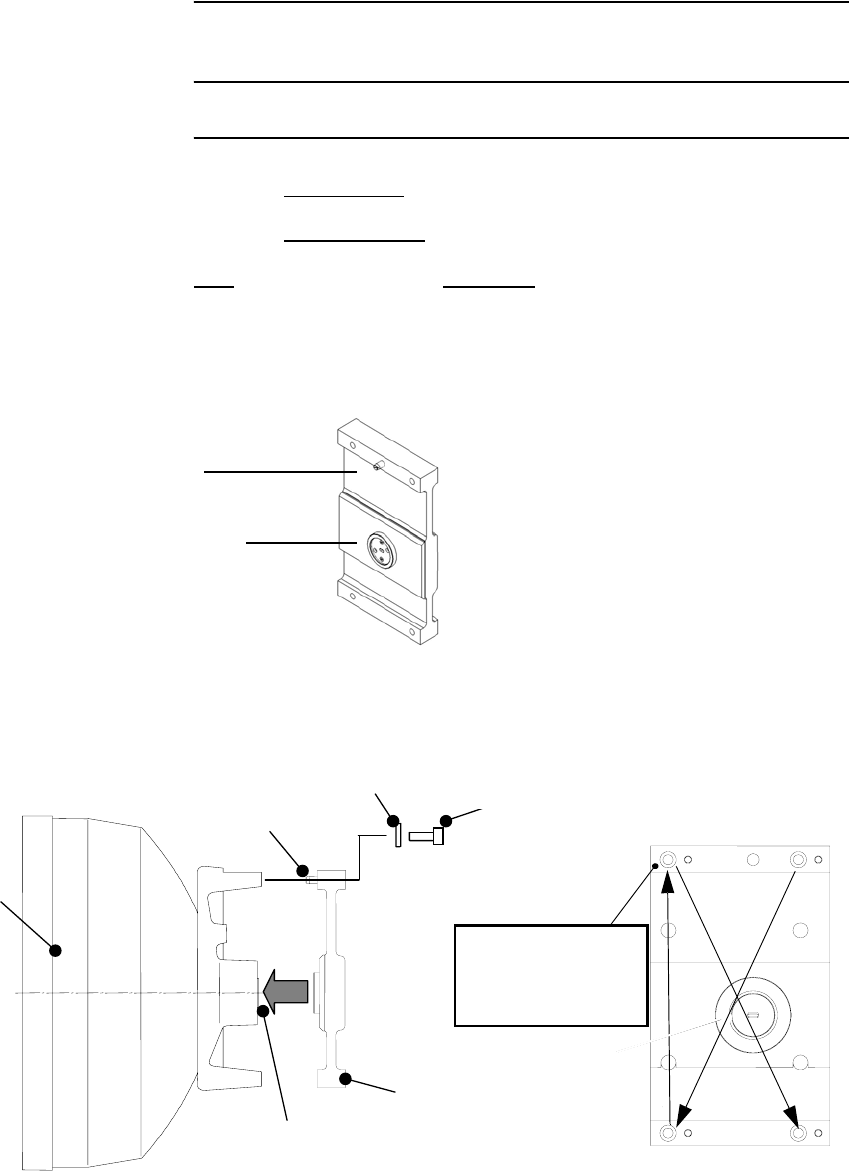
DEMOUNTING
FROM HYB
1 Remove the four (or six) fixed bolts from the ODU.
2 Then demount the ODU.
Note: When demounting the ODU from HYB, mount the attached
SHORT PLATE to the demounted port of the HYB to avoid RF
power leaking from the hybrid and for waterproofing.
MOUNTING SHORT
PLATE TO THE ODU
PORT
MOUNTING HOLE
FOR SHORT
PLATE
SHORT
PLATE
Note: Tightening torque is 3.0 N·m ± 10%.
INSTALLATION ROI-S05750
2-48
Chart 2-9 Antenna Direct Mounting Using
TX SPAN ATT
Step Procedure
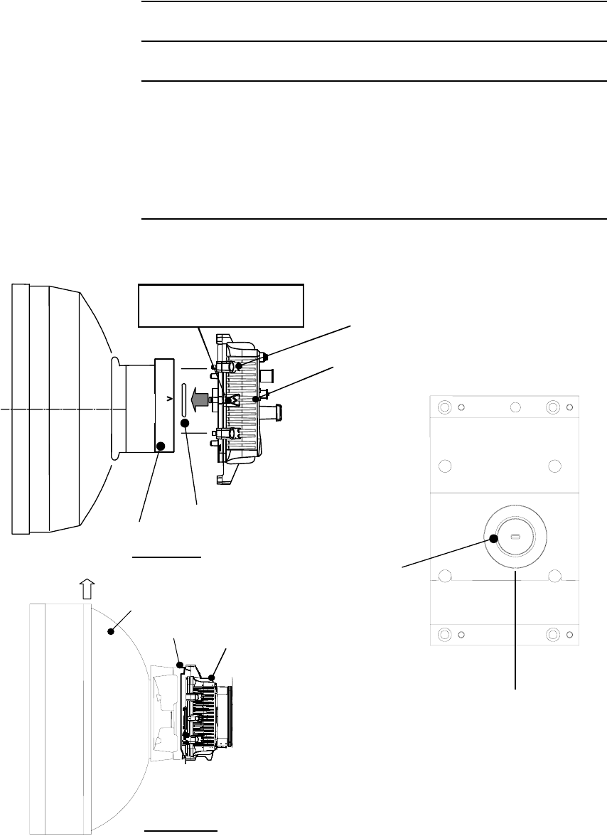
MOUNTING
TX SPAN ATT
Step Procedure
1 Check the polarization of the antenna connection unit of the TX
ATT (Refer to CHANGING POLARIZATION description for
the TX ATT.)
2 Fix the TX ATT to the antenna by tightening the M6 screws
(four locations).
Antenna Connection Unit
TX ATT
Antenna
Guide Pin
TX ATT
Flat Washer M6 (4ea)
Packing (Supplied by Antenna)
Installation to antenna
12
34
Note; Tightening torque (M6) is 4.0 N·m ± 10%.
Hexagon Socket Head
Cap Screw
M6 x 30 (4ea)
38 GHz Band ODU Mounting Using NEC TX SPAN ATT (1/2)
Tighten the each
screw equally and
carefully by wrench
at diagonal position.
38A
ROI-S05750 INSTALLATION
2-49
Chart 2-9 (Cont’d)
Step Procedure
3 Insert the O-rings to port of the ODU.
4 Fix the ODU with hex screws (four locations) using the Allen
key wrench.
Note: Be careful not to damage the O-rings (TX ATT).
Attachment of ODU
Hexagon Socket
Head Cap Screw M6
(Supplied by NEC with ODU)
O-Ring
(Packing)
O-Ring
(Packing)
ODU Connection Unit
NEC ODU
TOP VIEW
SIDE VIEW
TX ATT ODU
Antenna
TOP
TX ATT
ODU should be attached
by turning “V” up.
Note: Tightening torque is 4.0 N·m ± 10%.
38 GHz Band ODU Mounting Using NEC TX SPAN ATT (2/2)
38A
INSTALLATION ROI-S05750
2-50
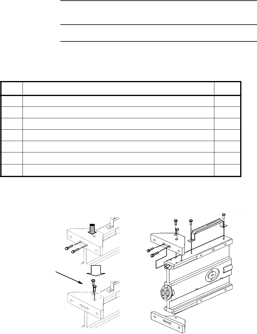
Chart 2-10 11-38 GHz Band ODU Mounting with HYB
(Waveguide Connection)
Step Procedure
WAVEGUIDE CONNECTION FOR 1+1 HYB
Notr:*For 4 screws Type Bracket
1 Assemble the bracket and handle to the HYB.
No. Parts Name Q’ty
1Hybrid (Waveguide Flange Interface Type) 1
2Bracket 2
3Handle 1
4O-ring (for ODU) 2
5O-ring (for Waveguide) 1
6M5 × 12 Hexagon Socket Head Cap Screw (SS) 10(14)*
7M3 ×10 Hexagon Head Screw with Washer (×4) (SS) 4
M5 HEAD CAP SCREW
Note: Tightening torque is 3.0 N·m ± 10%.
ROI-S05750 INSTALLATION
2-51
Chart 2-10 (Cont’d)
Step Procedure
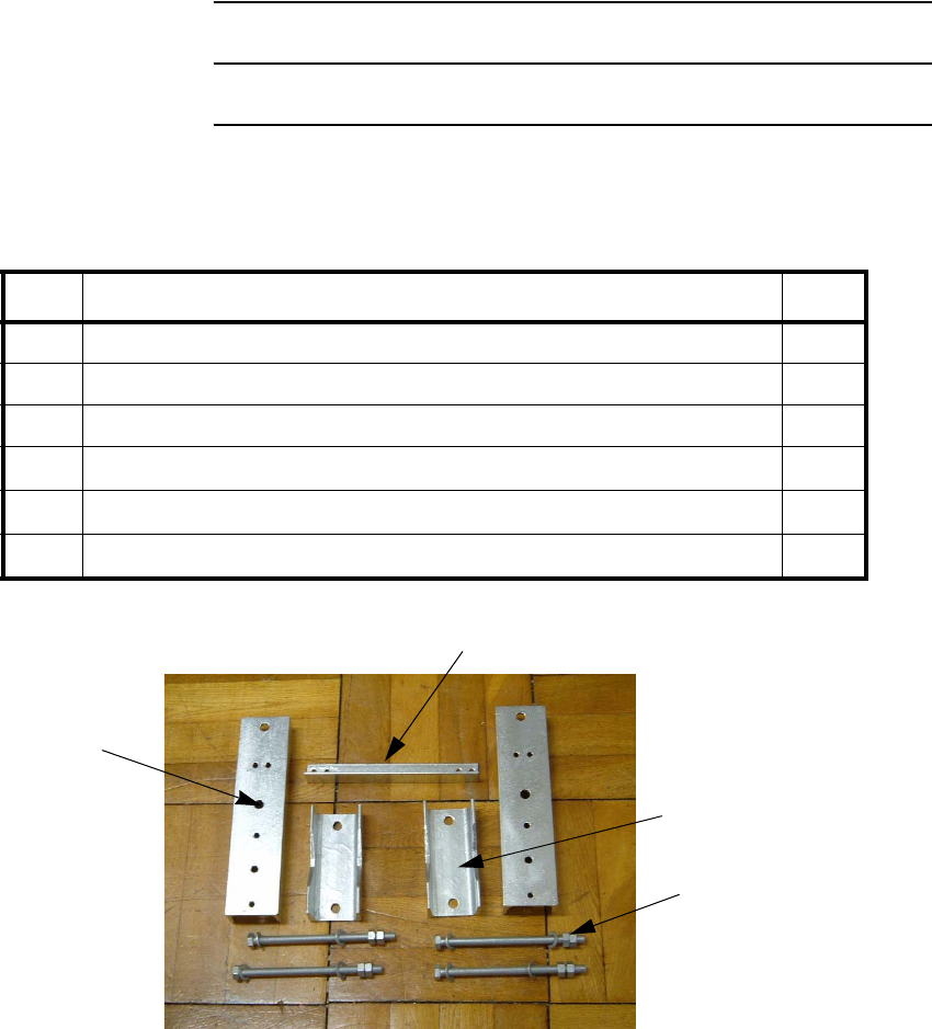
2 Assemble parts of the pole mounting bracket used to mount the
HYB,
No. Parts Name Q’ty
1Mount Arm 2
2Mount Holder 2
3Truss 1
4M12 × 200 Hexagon Head Screw with Nut (×2), Flat Washer (×2)(ST) 4
5M6 ×25 Hexagon Head Screw with Nut (x1), Flat Washer (×2), Spring Washer (SS) 4
6M6 × 35 Hexagon Head Screw with Nut ( ×2), Flat Washer (×2)(SS) 4
Mount Arm
Truss
Mount Holder
M12 × 200 Screw
INSTALLATION ROI-S05750
2-52
Chart 2-10 (Cont’d)
Step Procedure
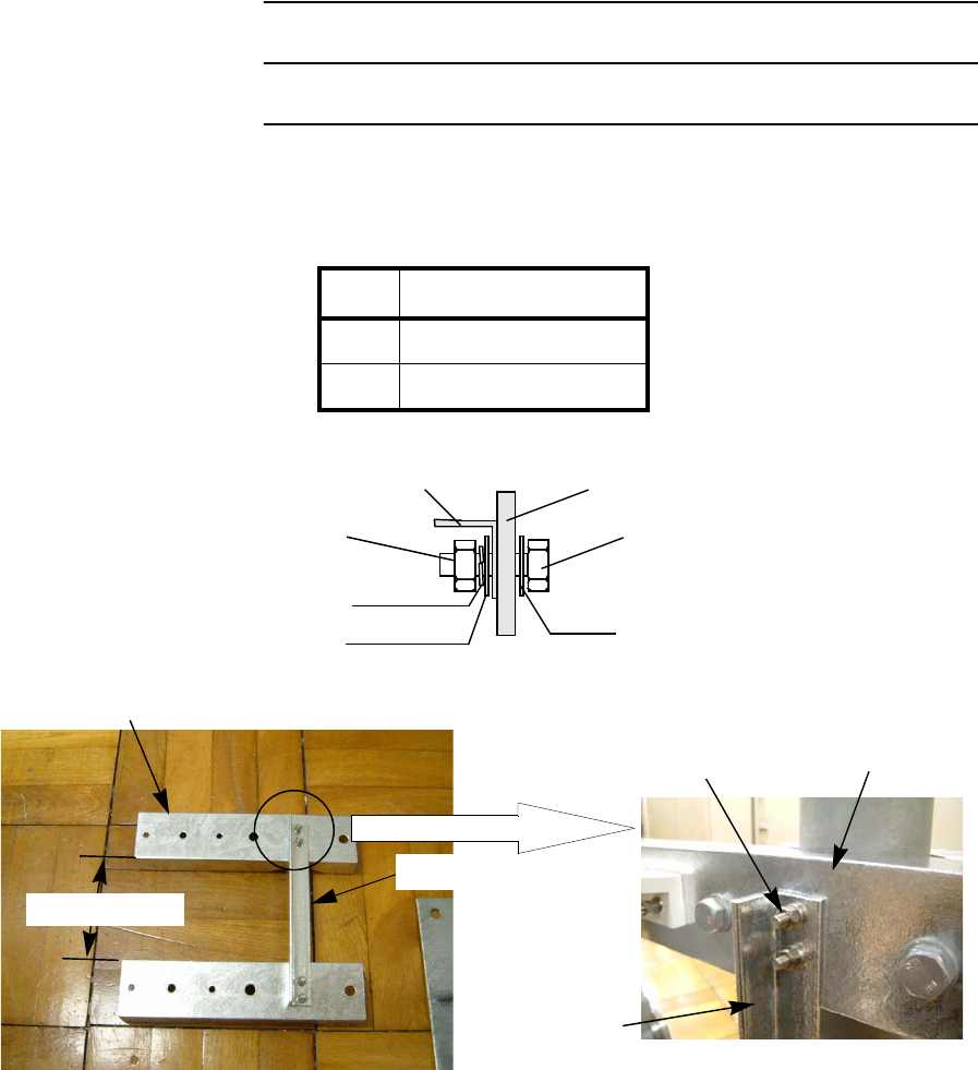
3 Screw the Mount Arm and the Truss with the M6 × 25 Screw,
Flat Washer (×2), Spring Washer (1), Nut, at four positions,
Tightening Torque
M6 4.0 N·m ± 10%
M12 47 N·m ± 10%
Mount Arm
Mount Arm
M6x25 Screw, Nut,
Flat Washer x 2
Spring Washer
Truss
Truss
Ab.144.3 mm
Mount Arm
Truss
M6 x 25 Screw
Flat Washer
Spring Washer
Flat Washer
Nut
ROI-S05750 INSTALLATION
2-53
Chart 2-10 (Cont’d)
Step Procedure
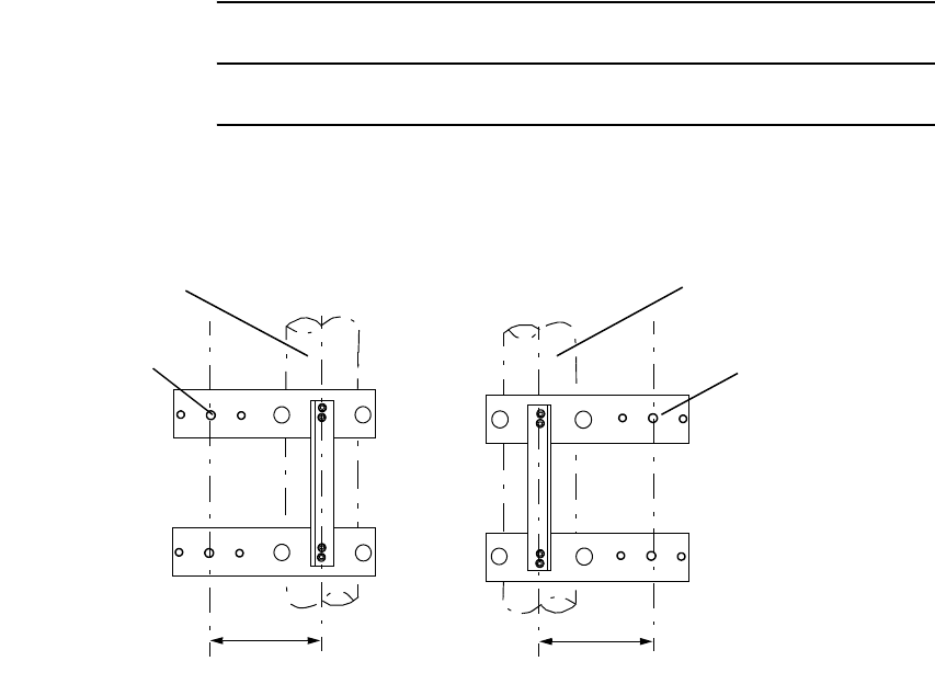
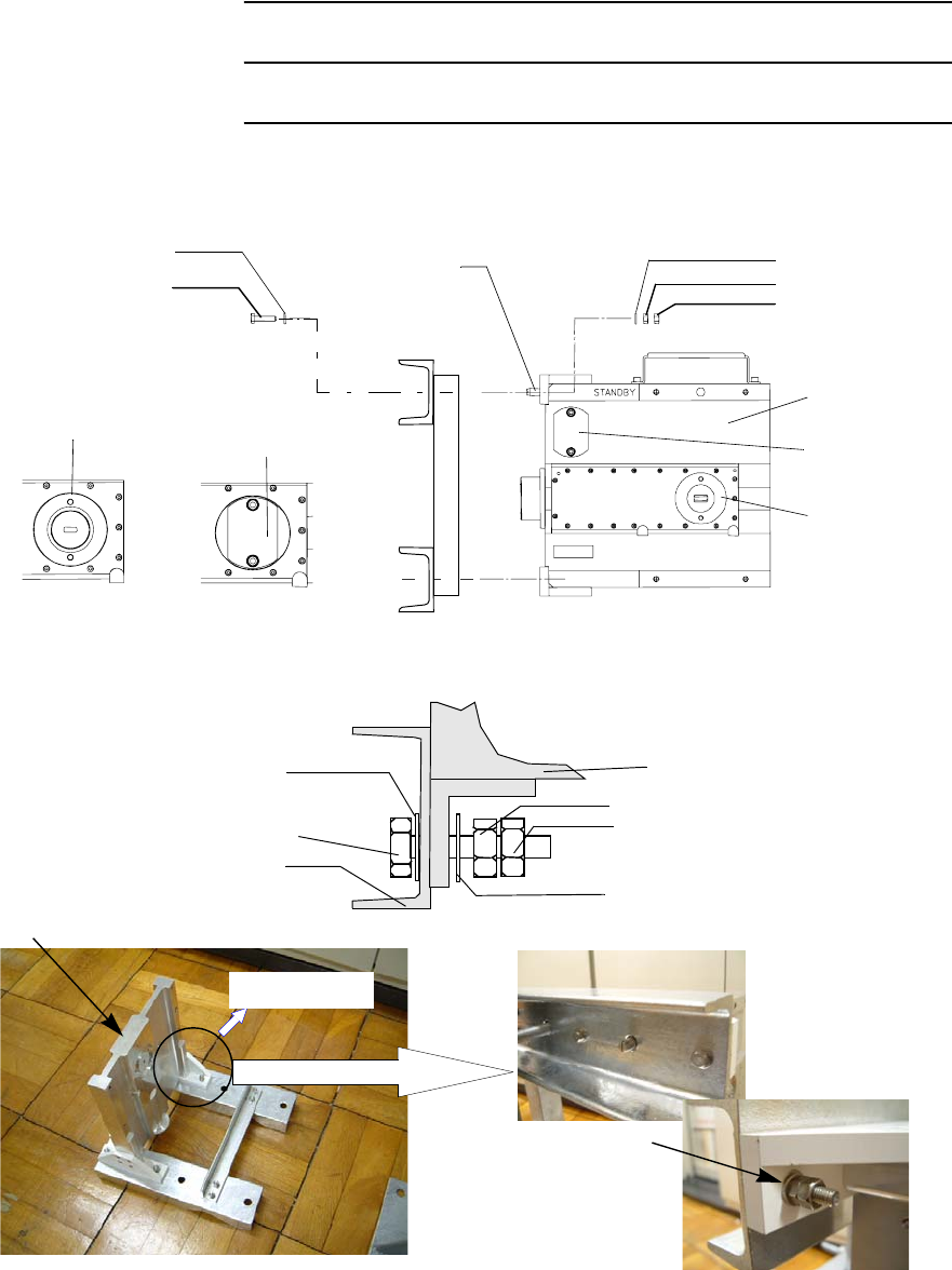
4 Determine centre off set,
5 Fit the guide pin of the HYB to the Guide Pin Hole of the Mount
Arm,
6 Install the HYB onto the bracket with the M6 × 35 Screw, Flat
Washer (×2), Nut (×2), at four positions,
Mounting PipeMounting Pipe
Centre Off Set
Centre Off Set
Guide Pin Hole
(HYB Top)
Guide Pin Hole
(HYB Top)
INSTALLATION ROI-S05750
2-54
Chart 2-10 (Cont’d)
Step Procedure
HYB
M6x35 Screw,
Nut x 2
Flat Washer x 2
HYB Top
M6x35 Screw
Flat Washer
Nut
Nut
Flat Washer
HYB
Guide Pin
Short Plate
Note: When either Main or Standby ODU is removed, attach the short plate over
the ODU port. Tightening torque is 3.0 N·m ± 10%.
ODU Port Short Plate
ODU Port
Mount Arm
M6 x 35 Screw
Flat Washer
Flat Washer
Nut
Nut
HYB
ROI-S05750 INSTALLATION
2-55
Chart 2-10 (Cont’d)
Step Procedure
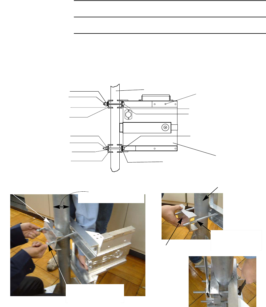
7 Install the HYB to the mounting pole using the M12 × 200
Screw, Flat Washer, Nut,
Mount Holder Pole Diameter
: ø50 to ø115mm
Mount Holder
M12x200 Screw,
Nut x 2
Flat Washer x 2
M12x200 Screw,
Nut x 2
Flat Washer x 2
Mount Holder
M12 x 200 Screw
Flat Washer
Flat Washer
Nut
Nut
HYB
Mounting Pole
Mount Holder
Flat Washer
Nut
Nut
Flat Washer
M12 x 200 Screw
Mounting Pole
Guide Pin Hole
INSTALLATION ROI-S05750
2-56
Chart 2-10 (Cont’d)
Step Procedure
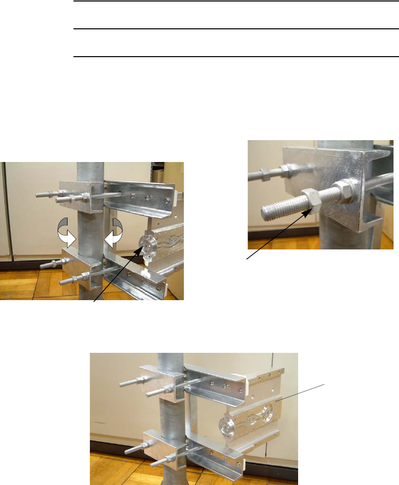
8 Adjust direction of the Bracket for Waveguide Port of the HYB
orientation,
9 Confirm the ODU Type, which is Master or Slave,
Caution: The same type must be installed onto the HYB.
Tighten double nut after orientation for
waveguide connection has been decided.
Double Nut tightening
Determination of the attachment direction.
Waveguide Port
HYB
ROI-S05750 INSTALLATION
2-57
Chart 2-10 (Cont’d)
Step Procedure
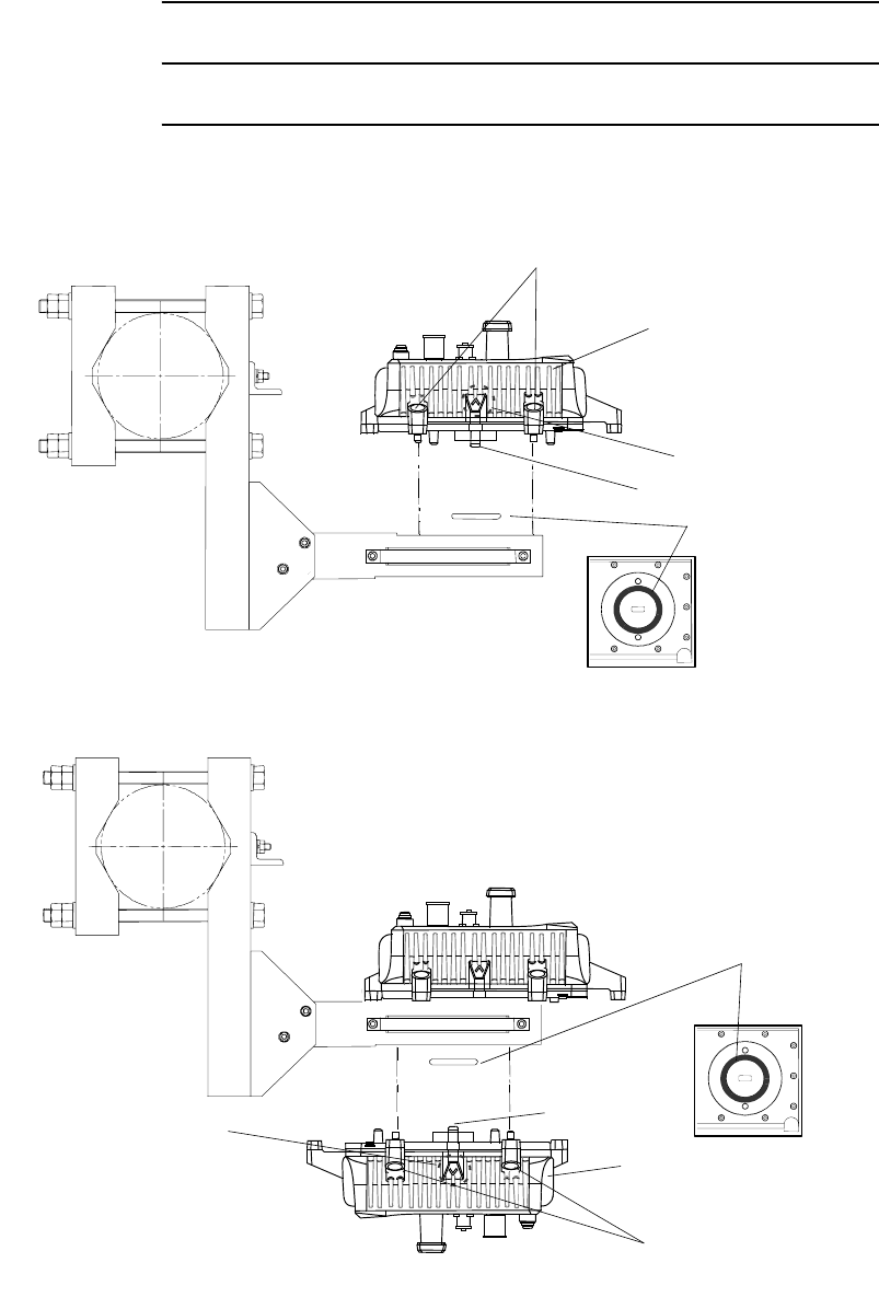
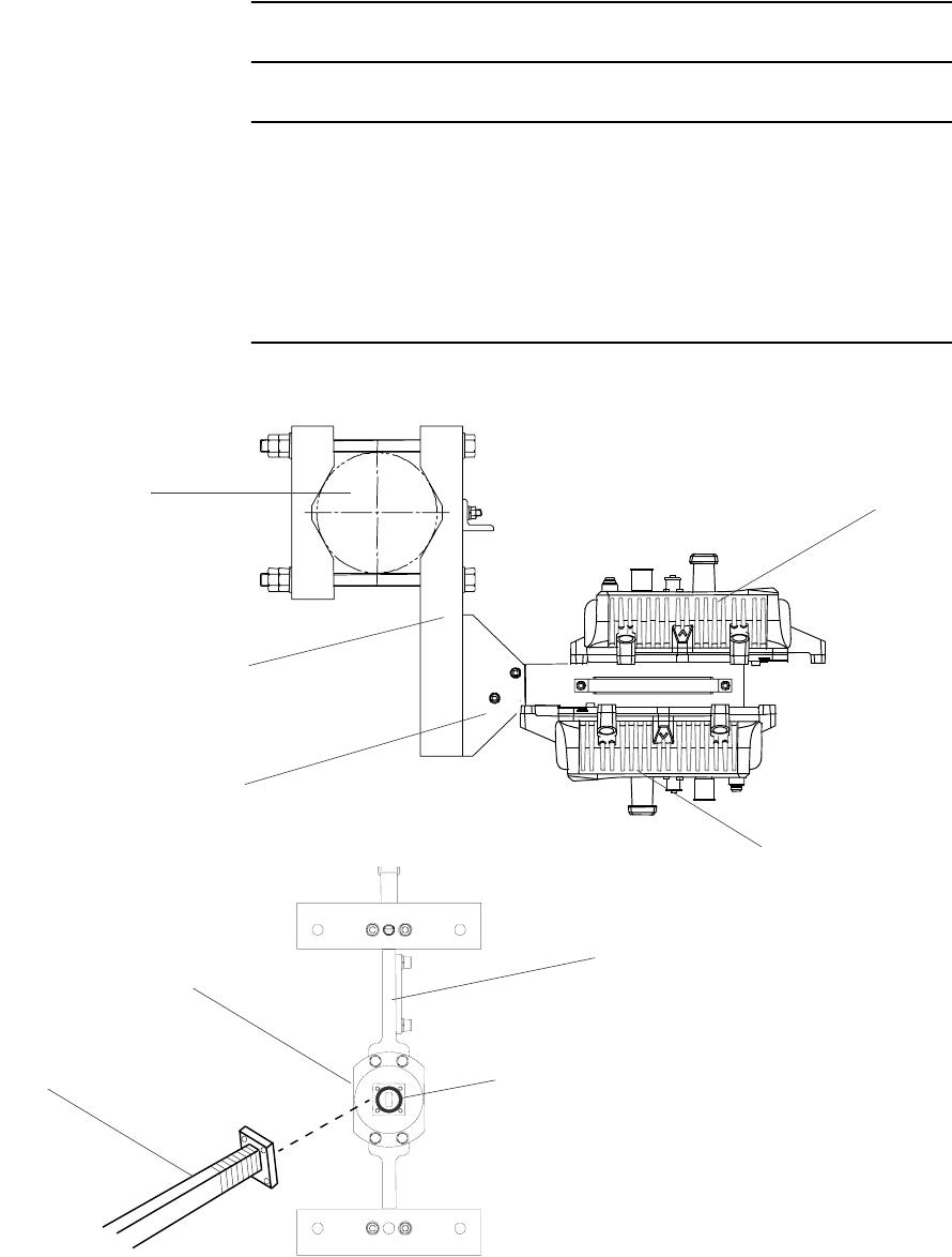
10 Install the ODU onto the HYB,
Hexagon Socket Head Cap Screw
Main ODU
O-ring
Note: The ODU should be attached by turning the plate marked “V” up position
for both Main ODU and Standby ODU.
Standby ODU
O-ring
Guide Pin
Mark V to Top
Mark V to Top
(Top View)
(Top View)
Hexagon Socket Head
Cap Screw
Guide Pin
INSTALLATION ROI-S05750
2-58
Chart 2-10 (Cont’d)
Step Procedure
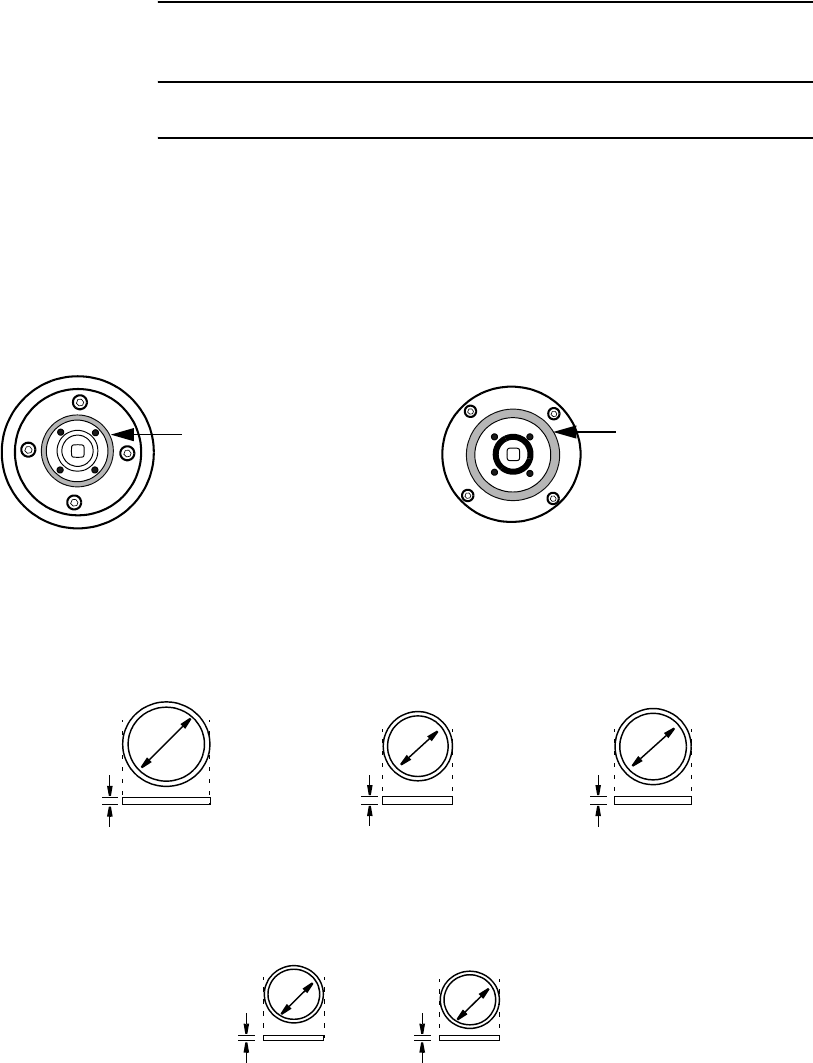
11 Connect the flexible waveguide (WG) to the ODU and fix the
waveguide to the ODU with four (4) bolts.
Note: Before connecting the WG to the antenna, confirm which
polarization is applied to the Master and Slave ODU.
O-ring
WG Port
HYB
Mounting Pole
Pole Mounting Bracket
HYB
WG
Note:Be careful not to damage the O-ring.
Main ODU
Standby ODU
Note: Tightening torque is 1.4 N·m ± 10%.
ROI-S05750 INSTALLATION
2-59
Chart 2-11 11-38 GHz Band ODU Mounting with OMT
(Antenna Direct Mounting)
Step Procedure
This section explains the installation of the OMT for XPIC system.
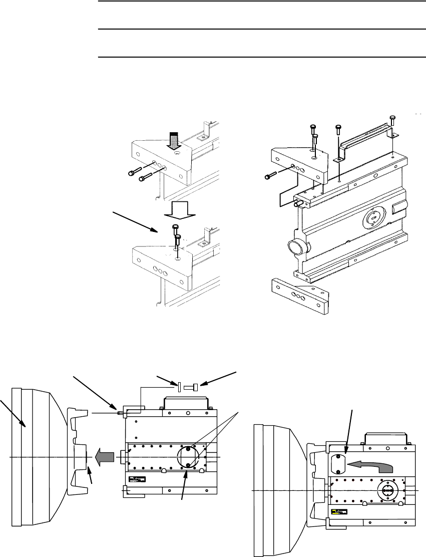
There are two types of O-rings for antenna mounting to the OMT
depending on the frequency band.
Caution : Do not apply silicon grease to O-ring.
Notes: 1. O-ring size is different with frequency band as follows:
POSITION OF LARGE
SIZE O-RING
FOR ANTENNA DIRECT MOUNTING
RFS ANTENNA
POSITION OF LARGE
SIZE O-RING
FOR ANTENNA DIRECT MOUNTING
ANDREW ANTENNA
32mm
35mm
LARGE SIZE O-RING FOR ANTENNA DIRECT MOUNTING
26-38 GHz BAND13-23 GHz BAND
4 mm
4 mm
40mm
10-11 GHz BAND
4 mm
13-23 GHz BAND 38 GHz BAND
15.6mm
SMALL SIZE O-RING FOR WAVEGUIDE CONNECTION
10.8mm
1.8 mm
1.8 mm

INSTALLATION ROI-S05750
2-60
Chart 2-11 (Cont’d)
Step Procedure
For the antenna direct mounting of the ODU, following OMT is used in
the XPIC system.
Caution : For connecting the OMT to the antenna, the circular type
waveguide flange of the antenna is applied to the XPIC
system. When the V/H flange is mounted to the antenna, it
must be changed to a circular type.
Caution : When mounting the ODU to the OMT, confirm the
polarization for Main Master and SUB Master ODU. The
installation of the corresponding ODUs in the opposite
station must have the same polarization in order to make
into line Main Master and SUB Master MODEMs.
FREQUENCY
BAND FREQUENCY
RANGE (GHz) OMT
CODE No.
INTERFACE WG
INNER DIA.(mm)
(ANT Side)
INTERFACE
(ODU Side)
11G 10.7 −11.7 GHz G9380A 18.0 R100
13G 12.75 −13.25 GHz G9381A 15.0 R140
15G 14.5 −15.35 GHz G9382A 13.5 R140
18G 17.7 −19.7 GHz G9383A 10.5 R220
23G 21.2 −23.6 GHz G9384A 9.0 R220
26G 24.5 −26.5 GHz G9385A 8.0 R260
32G 31.8 −33.4 GHz G9387A 6.5 R320
38G 37 −39.5 GHz G9388A 5.5 R320
ROI-S05750 INSTALLATION
2-61
Chart 2-11 (Cont’d)
Step Procedure
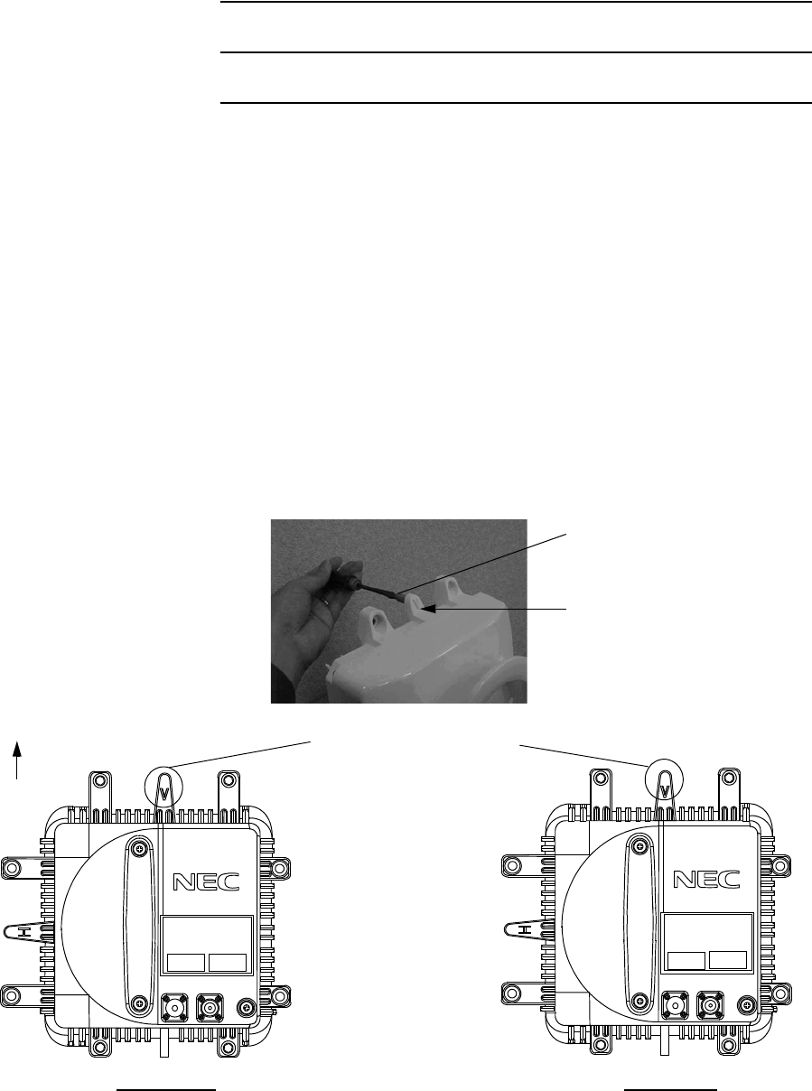
1 Fix the bracket and handle to the OMT.
2 Fix the OMT to the antenna by tightening them with M6 screws
(four locations),
M5 HEAD CAP SCREW
Note: Tightening torque is
3.0 N·m ± 10%.
ANT
FLAT WASHER M6 M6 SCREWGUIDE PIN
O-ring
SHORT PLATE
MOVE THE
SHORT PLATE
SCREW
Note: Tightening torque is 4.0 N·m ± 10%. Note: Be careful not to damage the O-ring.
Note: Tightening torque is
3.0 N·m ± 10%.
INSTALLATION ROI-S05750
2-62
Chart 2-11 (Cont’d)
Step Procedure
3 Loosen the two screws and move the short plate if it is fixed to
the ODU port. (see figure in step 9),
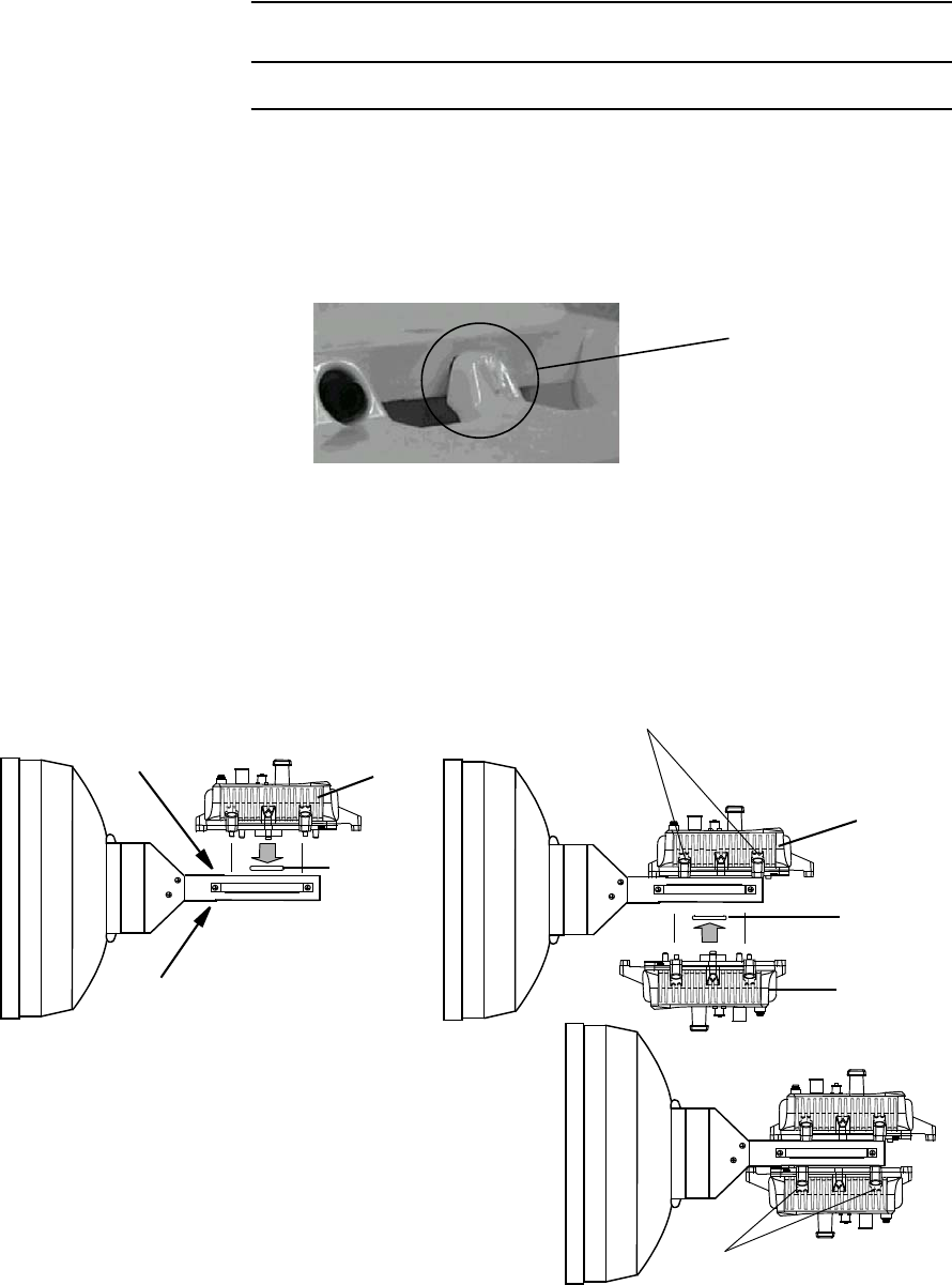
4 Set the two ODUs to vertical polarization for OMT mounting.
If the guide pin behind the plate marked H is mounted, remove
the guide pin,
Note: The ODU should be attached by turning the plate marked
"V" up position for both Main Master ODU and SUB
Master ODU.
5 Insert the guide pin removed in step 4 behind the plate marked
V,
Note: Remove the protection metallic plate covering the
waveguide hole on ODU.
GUIDE PIN
PLATE MARKED WITH V
Main Master Sub Master
PLATE MARKED WITH V
UP
FG
IFL
MON
RX LEV FG
IFL
MON
RX LEV
NLite E NLite E
ROI-S05750 INSTALLATION
2-63
Chart 2-11 (Cont’d)
Step Procedure
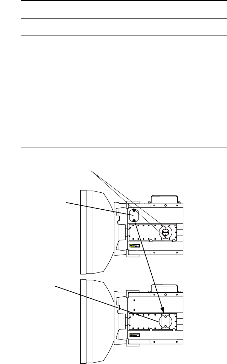
6 Insert the O-rings to the two ODU ports of the OMT (see figure
in step 9),
7 Insert the guide pin into the hole of the OMT and set the
position of screws,
8 Confirm which polarization is applied to the Master ODU.
Check the indication of polarization on the upper side of OMT.
9 Fix the two ODUs with hex screws (four locations) using the
allen key wrench,
Note: Be careful not to damage the O-rings.
GUIDE PIN
O-ring
ODU
O-ring
ODU
ODU
HEX SCREW
H
POLARIZATION
SIDE
V
POLARIZATION
SIDE
HEX SCREW
Note: Tightening torque is 4.0 N·m ± 10%.
INSTALLATION ROI-S05750
2-64
Chart 2-11 (Cont’d)
Step Procedure
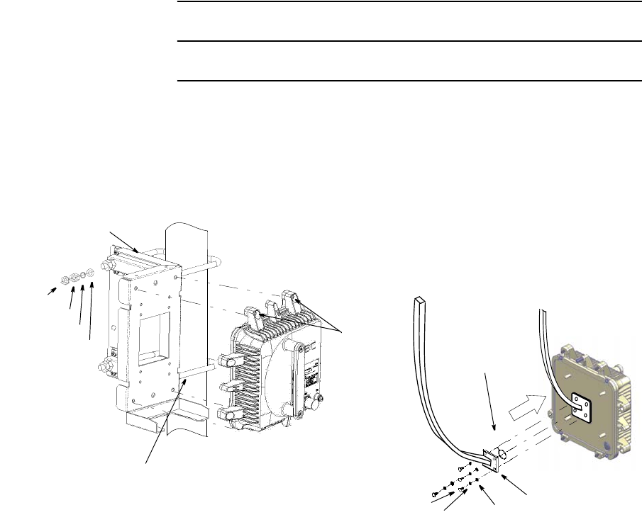
Cautions: 1. Tighten all screws with lighter torque at first, then full
torque as specified.
2. When either ODU is demounting for ODU replacing or
other reasons, fix the attached short plate to the
demounted port of the OMT to avoid leaking of RF
power from the OMT and for waterproof.
3. To avoid occurrence of bit errors due to microphonic
properties, when installing the SUB Master ODU,
protect the Main Master ODU from mechanical knocks.
FIXED SHORT
PLATE TO THE ODU
PORT
FIXING HOLE FOR
SHORT PLATE
SHORT
PLATE
Note: Tightening torque is
3.0 N·m ± 10%.
ROI-S05750 INSTALLATION
2-65
2.7 Feeder Connection
The connection method of the waveguide type ODU is described in
following procedure.
Chart 2-12 Wave Guide Connection
Step Procedure
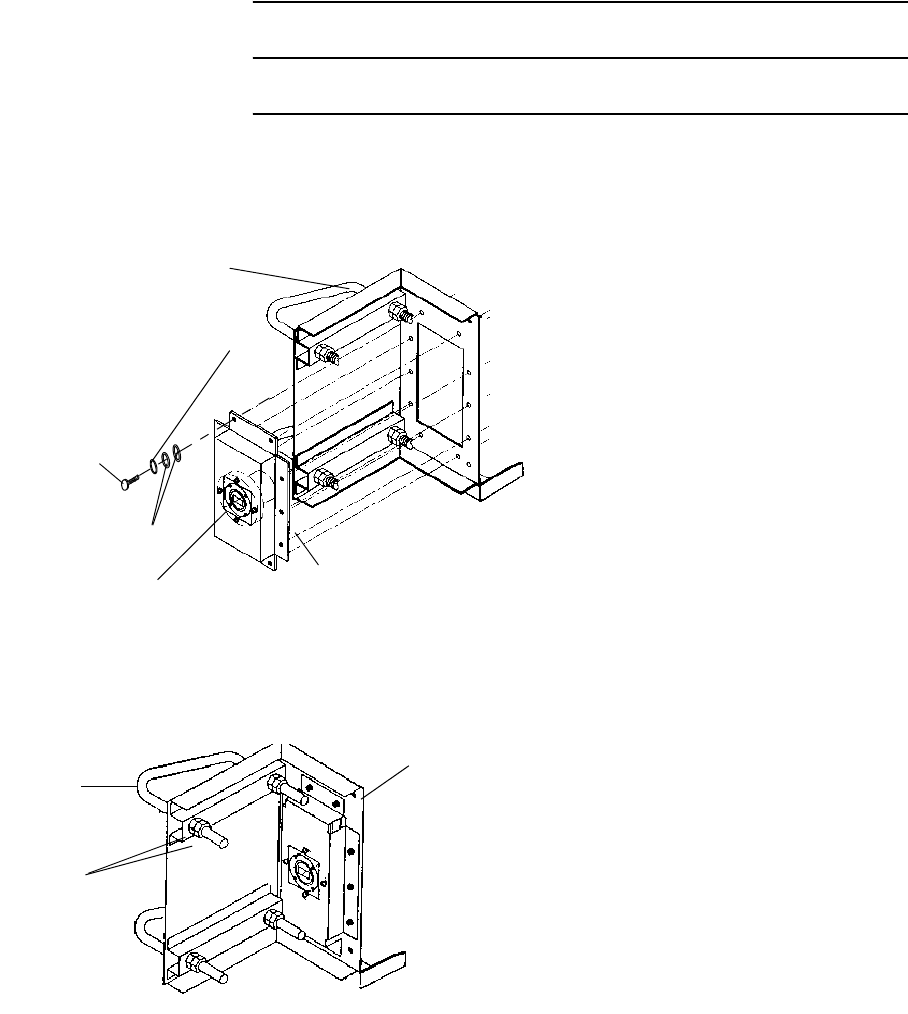
1 Mount a waveguide to the ODU, fix the waveguide to the ODU
with four bolts.
WASHER
O- RING
WAVEGUIDE
BOLT (M4)
SPRING WASHER
THIN NUT
THICK NUT
S
PRING WASHER
FLAT WASHER
U-BOLT
MOUNTING BRACKET
M6
Tightening torque:
4.0 N·m ± 10%
Note: Tightening torque is 1.4 N·m ± 10%.
Note: Be careful not to damage the O-ring.
Notes: 1. Use suitable flange adapter between ODU and waveguide
depending on the waveguide type.
2. Connection of the waveguide is the same way as ODU is
wall mounted or 19-inch rack mounted.
The wave guide for the antenna direct mounting type ODU is flange
adapter is required. Refer to the following procedure.
INSTALLATION ROI-S05750
2-66
Chart 2-12 (Cont’d)
Step Procedure
1 Mount the attachment with adapter to the ODU bracket using
ten bolts,
ATTACHMENT
SPRING WASHER
WASHER
ODU BRACKET
PBR ADAPTER
Note: Color of adapter is white.
BOLT (M5 ×10)
Tightening torque:
3.0 N·m ± 10%.
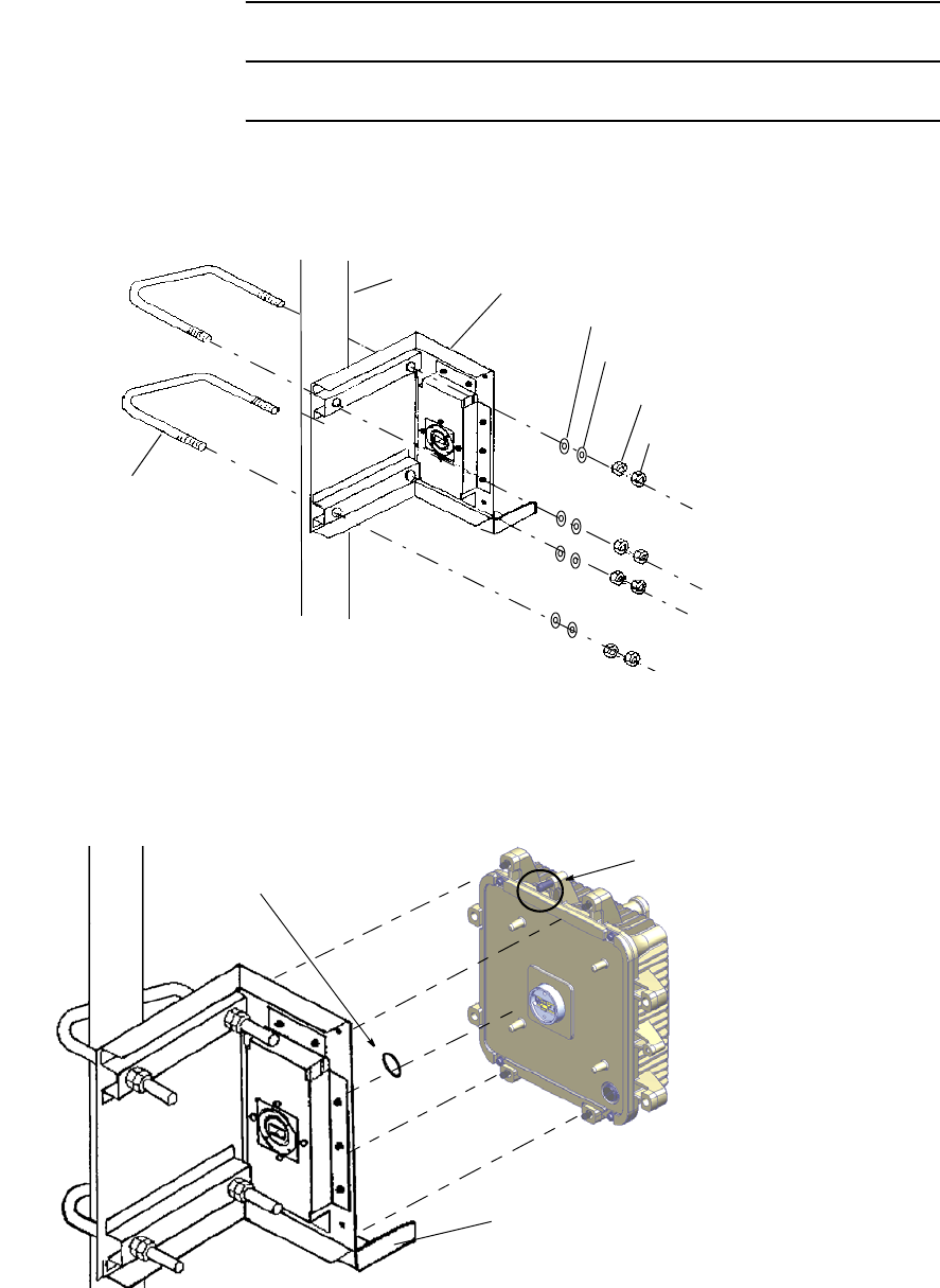
2 Loosen eight nuts and remove the two U-bolts from the ODU
bracket,
U-BOLT ODU BRACKET
NUT
ROI-S05750 INSTALLATION
2-67
Chart 2-12 (Cont’d)
Step Procedure
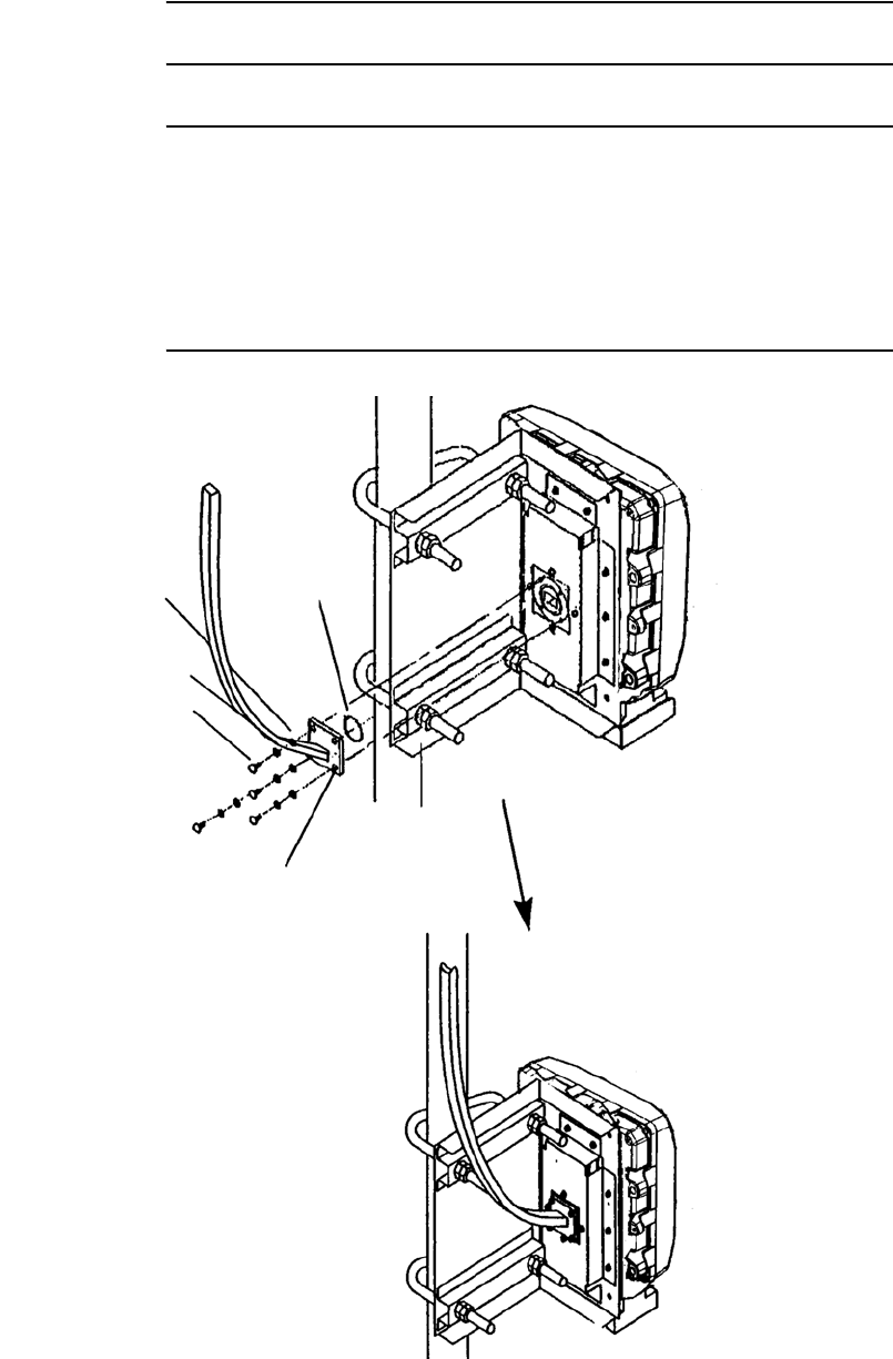
3 Mount the ODU bracket to the pole with two U-bolts,
ODU BRACKET
U-BOLT
POLE
FLAT WASHER
SPRING WASHER
THIN NUT (M10)
THICK NUT (M10)
Tightening torque: 34.0 N·m ± 10%
Note: The diameter of the pole is from 48.5 to 114.5 millimeters.
4 Mount the ODU to the ODU bracket with attached four bolts
(Align the guide pins on the ODU and the guide holes on the
bracket),
ODU BRACKET
Antenna direct
mounting type ODU
with NEC special
flange.
O-RING
(Note)
GUIDE PIN
Note: Tightening torque is 4.0 N·m ± 10%.
Note: Be careful not to damage the O-ring.
INSTALLATION ROI-S05750
2-68
Chart 2-12 (Cont’d)
Step Procedure
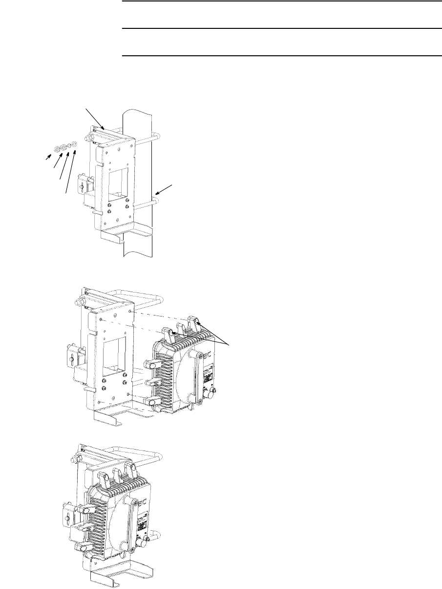
5. Make sure that the ODU and the ODU bracket are fixed at
specified values.
6 Mount the waveguide to the ODU with four bolts.
BOLT (M4)
SPRING WASHER
WASHER O-RING
WAVEGUIDE
WITH PBR( ) FLANGE
Note: Tightening torque is 1.4 N·m ± 10%.
Note: Be careful not to damage the O-ring attached to the PBR adapter.
ROI-S05750 INSTALLATION
2-69
Chart 2-13 ODU Mounting for Connecting Coaxial Cable
Step Procedure
6/7/8 GHz ODU MOUNTING (Connecting Coaxial Cable)
1. Mount the bracket to the pole, point
to the opposite station and tighten it
with two U-bolts,
Note:The diameter of pole is from 48.5 to
114.5 millimeters.
THIN NUT
THICK NUT
SPRING WASHER
FLAT WASHER
U-BOLT
MOUNTING BRACKET
2. Mount the ODU on to the bracket
and tighten four bolts (M6) at upper
and lower parts of the ODU,
M6
3. Check that the ODU and the bracket
are fixed firmly,
Tightening torque: 4.0 N·m ± 10%
Tightening torque:
34.0 N·m ± 10%
INSTALLATION ROI-S05750
2-70
Chart 2-13 (Cont’d)
Step Procedure
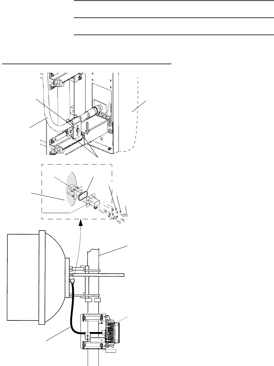
4. Connect the Coaxial cable to
the RF IN/OUT connector
of the ODU,
5. Down the cable fix bracket
to fix the Coaxial cable, then
tighten the two bolts,
6. Install the Coaxial cables
between the antenna and
ODU.
Note: Fix the coaxial cable to the pole or
member with cable hanger or cable
ties after antenna orientation has
been completed.
Caution: Wrap the coaxial cable
connection points with a self-
bonding tape for waterproof.
6/7/8 GHz ODU MOUNTING (Connecting Coaxial Cable)
COAXIAL
CABLE
ODU
BRACKET
TIGHTEN BOLTS (M5)
POLE
ODU
COAXIAL
CABLE
Tightening torque: 3.0 N·m± 10%
O-Ring
ANTENNA
Washer
Spring Washer
Bolt (M4)
Transducer
Note: Tightening torque is 1.4 N·m ± 10%.
Nut
(When the wave guide flange is
provided to the antenna port, fit
the transducer with eight bolts.)
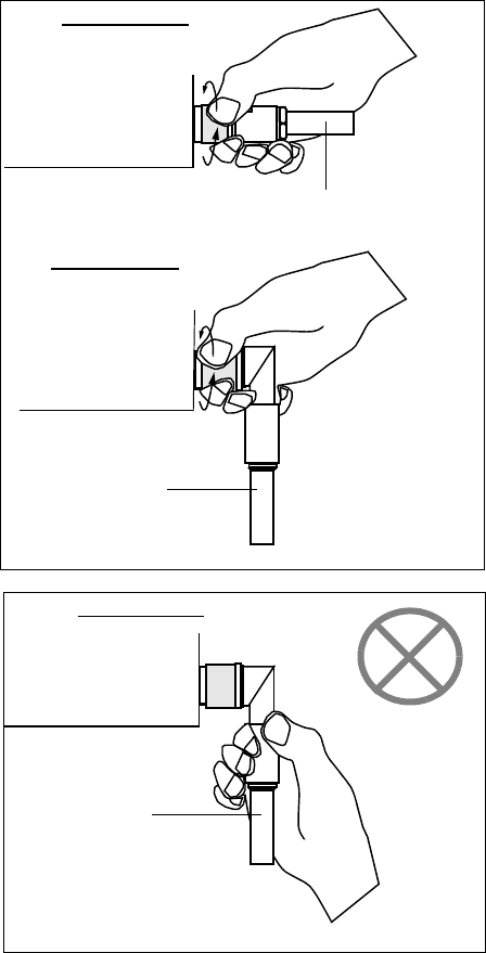
Caution
When connecting the IF cable to the
ODU, tighten the N-male connector
with engage connector nut only using
fingers and holding the cable with
another hand.
Tighten the engage connector nut
only for the L-angle connector also.
(Tightening Torque : 0.7 to 1.2 N•m
(7 to 12 kg•cm))
ODU
ODU
IF CABLE
IF CABLE
ODU
IF CABLE
Straight Type
L-Angle Type
L Angle Type
If rotate other parts of the L-angle
connector as illustrated left, it can
cause connector damage.
ROI-S05750 INSTALLATION
2-71
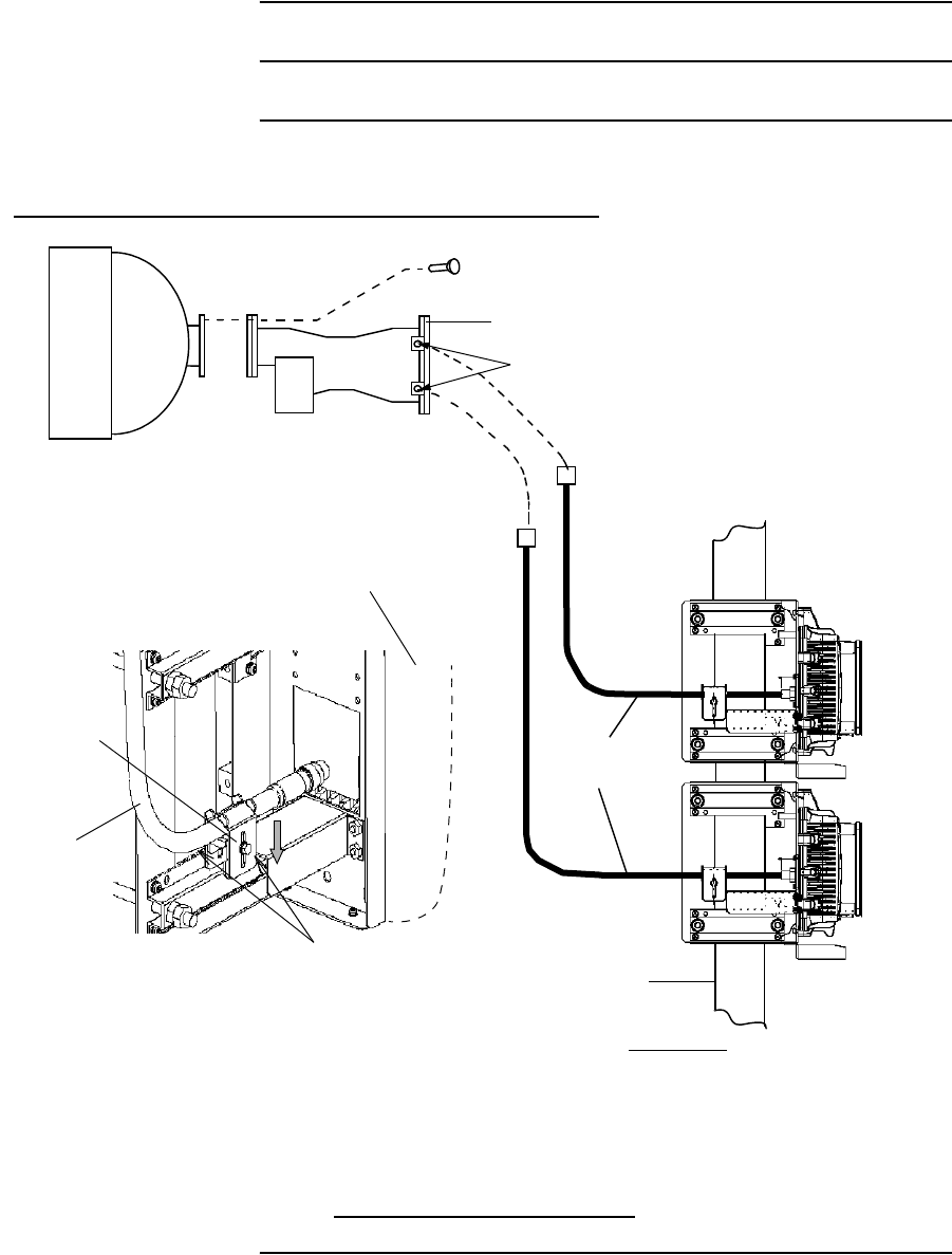
INSTALLATION ROI-S05750
2-72
Chart 2-13 (Cont’d)
Step Procedure
POLE
No.1 ODU
No.2 ODU
HYB
BOLT
ANT
N-Type *
COAXIAL
CABLE*
Note: * When coaxial cable with SMA connector is
used, the connectors are supplied by NEC.
USING HYB FOR 1+1 SYSTEM
SIDE VIEW
Caution: Wrap the coaxial cable connection points with a self-bonding
tape for waterproof.
COAXIAL
CABLE
ODU
BRACKET
TIGHTEN BOLTS (M5)
6/7/8 GHz ODU MOUNTING (Connecting Coaxial Cable)
Tightening torque: 3.0 N·m± 10%
ROI-S05750 INSTALLATION
2-73
2.8 Cable Termination
In this section, list of tools and material and the method for cable
termination method are described. The following cables are described for
reference.
• D-sub connector (refer to Chart 2-14)*
• TNC-P connector of the L angle type for IDU (refer to Chart 2-15)**
• N-P connector of the L angle type for ODU (KOMINE made) (refer
to Chart 2-16)**
• N-P connector of the L angle type for ODU (HIROSE made) (refer to
Chart 2-17)**
• N-P connector of the straight type for ODU (HIROSE made) (refer to
Chart 2-18)**
• N-P connector of the straight type for ODU (KOMINE made) (refer
to Chart 2-19)**
• Molex 5557-04R connector (refer to Chart 2-20)
• BNC connector soldering type (refer to Chart 2-21)
• BNC connector crimping type (refer to Chart 2-22)
• D-Sub High Density Crimp Contacts assembly (refer to Chart 2-23)*
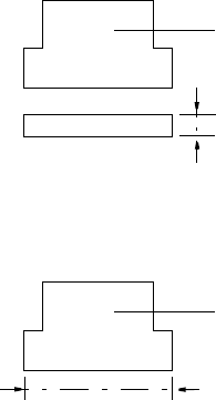
Notes: 1. *Use D-sub connectors of less than 16 mm in height as
illustrated below.
HEIGHT
D-SUB CONNECTOR
2. *Use D-sub 44-pins connector for the CTRL of less than 57
mm in width as illustrated below.
D-SUB 44 PIN CONNECTOR for the CTRL
WIDTH
3. **In 1+1 system, the difference between the No.1 channel
IF cable length and the No.2 channel IF cable length should
be within 100m. (differential absolute delay time : within
500 ns).
Note: Use shielded cables which are connected to the D-Sub/RJ-
45 connector to suppress interference from affecting the
signal and to reduce electromagnetic radiation which may
interfere with other signal cables.

INSTALLATION ROI-S05750
2-74
The tools and materials summarized in Table 2-5 are necessary.
Table 2-5 Tools and Material List
No. NAME REMARKS
1Soldering Iron
2Solder
3Knife
4Measure/Ruler
5Wire Stripper
6Adjustable Wrench
7Hand Crimping Tool
CL250-0012-2/
CL250-0013-5 For D-Sub connector
57026-5000/
57027-5000 For Molex connector
09 99 000 0596/
09 99 000 0513 For D-Sub High density
connector
ROI-S05750 INSTALLATION
2-75
Chart 2-14 Terminating Supervisory Cables with D-Sub
Connector
Step Procedure
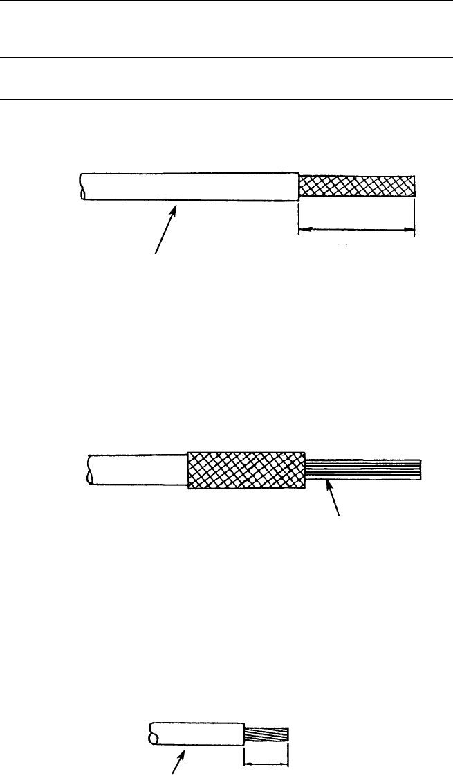
1 Strip back the cable sheath, taking care not to damage the
braided shield.
50 mm
CABLE
Note: Use shielded cables which are connected to the D-Sub
connector to suppress interference from affecting the
signal and to reduce electromagnetic radiation which may
interfere with other signal cables.
2 Fold back the braided shield (do not separate the strands) and
trim it as shown.
WIRE
3 Remove 4 mm of insulation from the end of the wire.
CONFORMABLE
WIRE SOCKET CONTACT
AWG#20-24 :CD-PC-111
AWG#24-28 :CD-PC-121
WIRE 4 mm
INSTALLATION ROI-S05750
2-76
Chart 2-14 (Cont’d)
Step Procedure
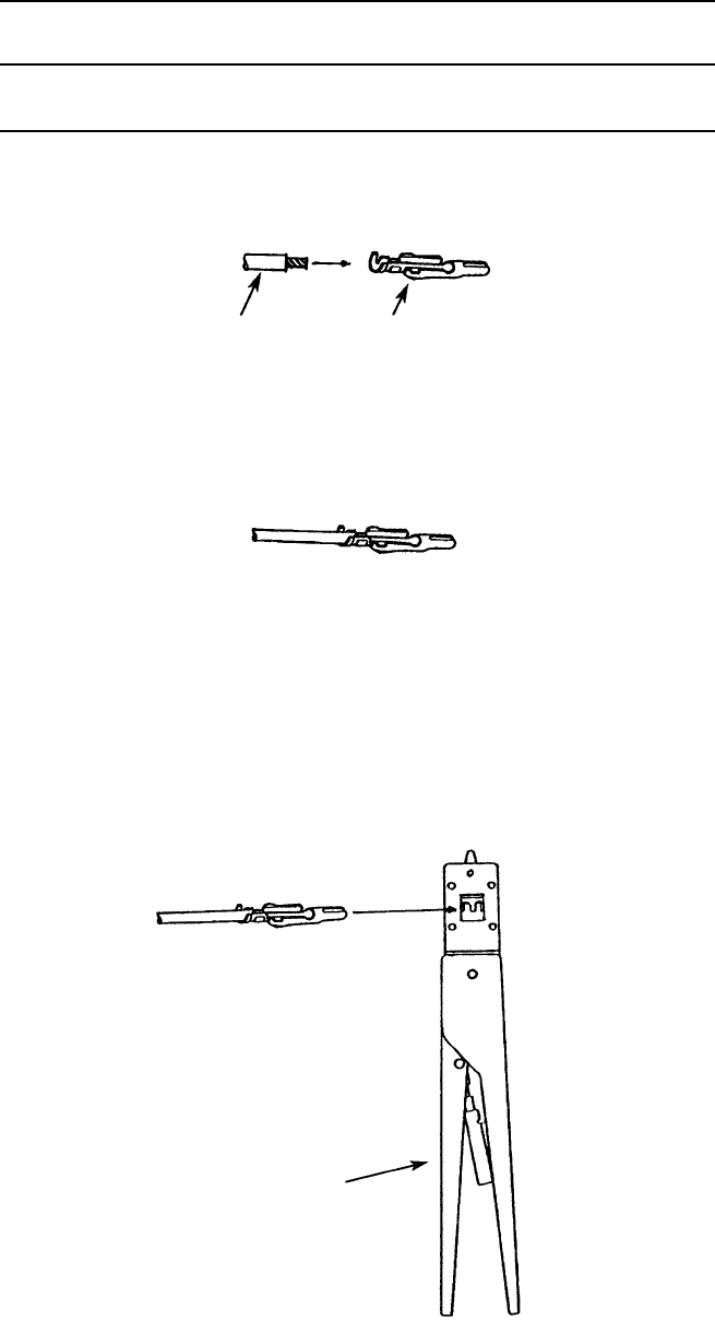
4 Insert the cable into the socket contact.
WIRE SOCKET CONTACT
5 The cable should be fitted so that insulation and bare wire are
arranged as shown.
6 Insert the socket contact into the hand crimping tool.
CONFORMING
WIRE SOCKET CONTACT
AWG#20-24 :TC-CD-111
AWG#24-28 :TC-CD-121
HAND CRIMPING TOOL
(HRS TC-CD-111/TC-CD-121)