NEC 07208901 LTE Base Station User Manual Installation Guide
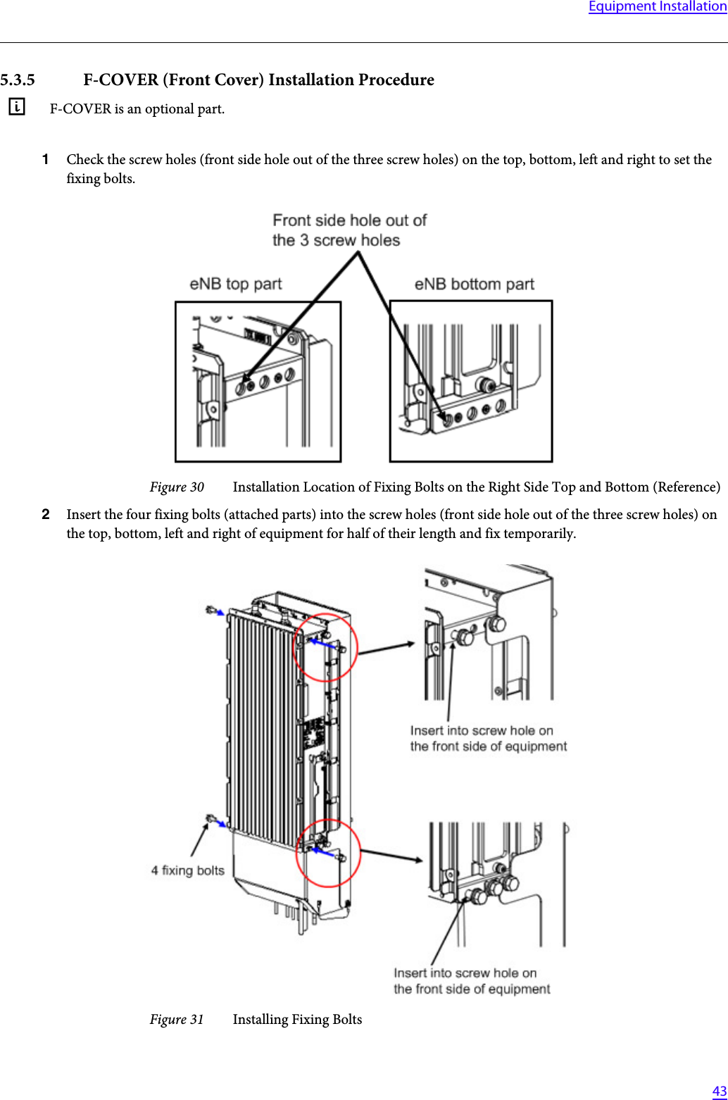
NEC Corporation LTE Base Station Installation Guide
UserManual.wiki
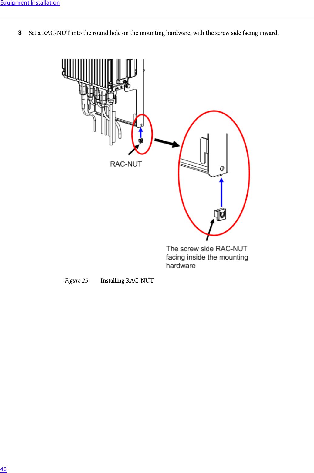
>
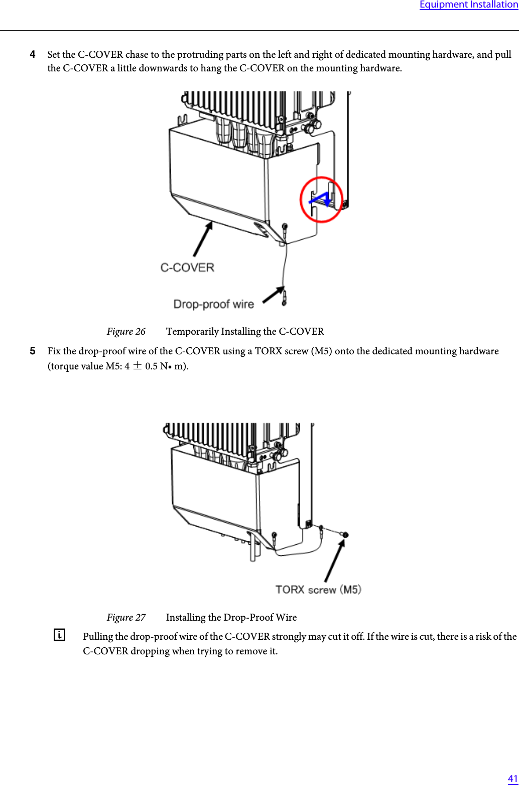
NEC
>
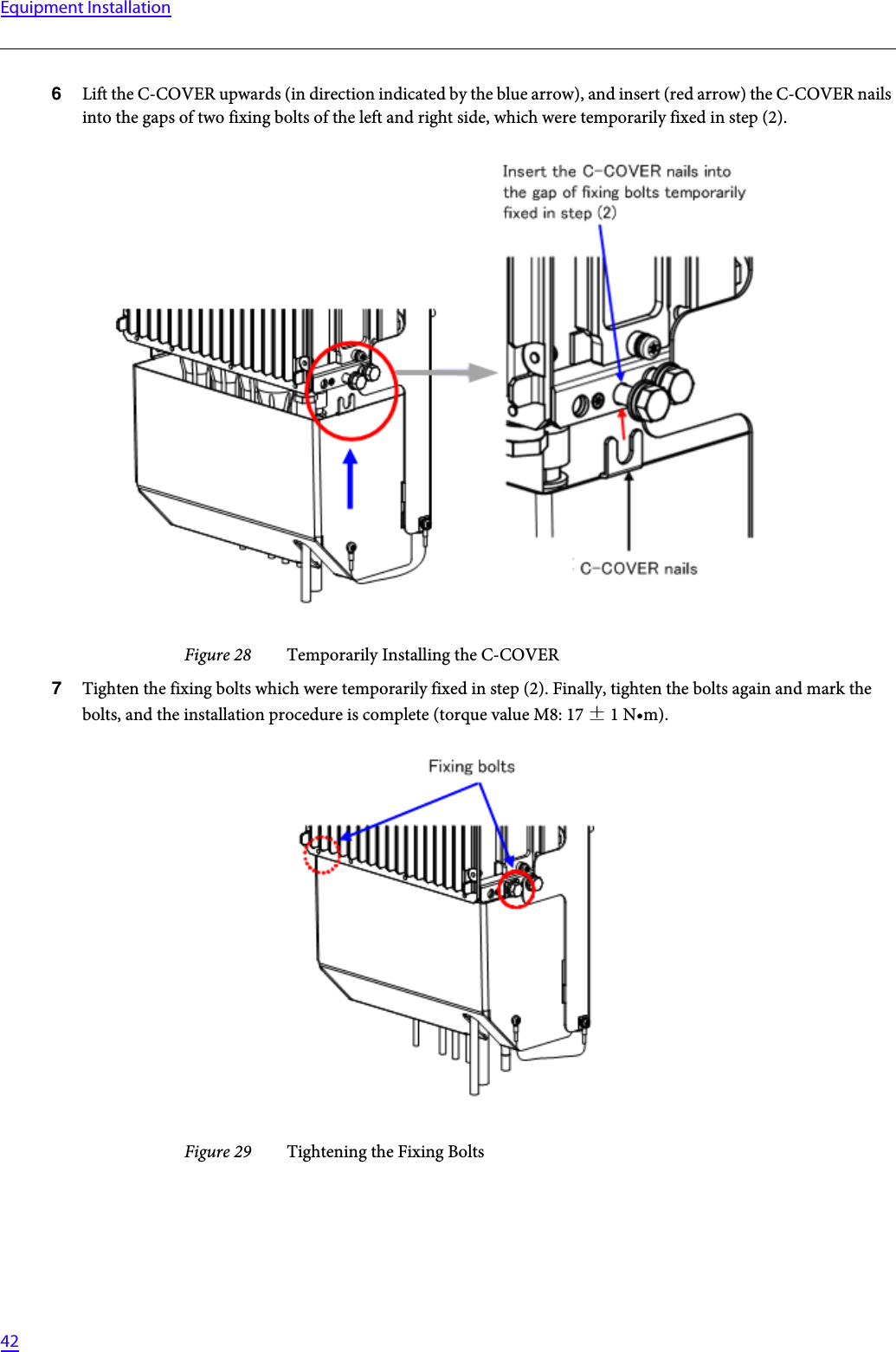
07208901 User Manual
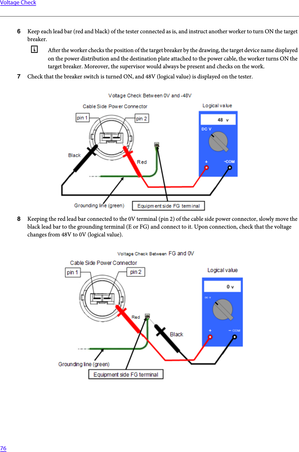
Installation Guide
Navigation menu
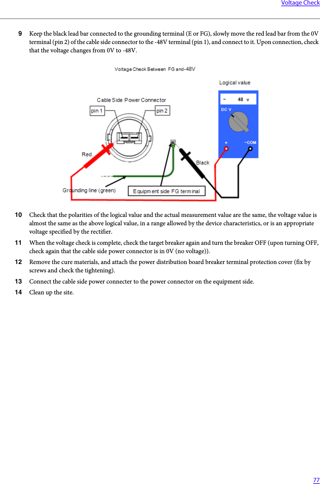
Upload a User Manual
Namespaces
Wiki Guide
HTML
PDF
Info
Views
User Manual
Discussion / Help
Navigation

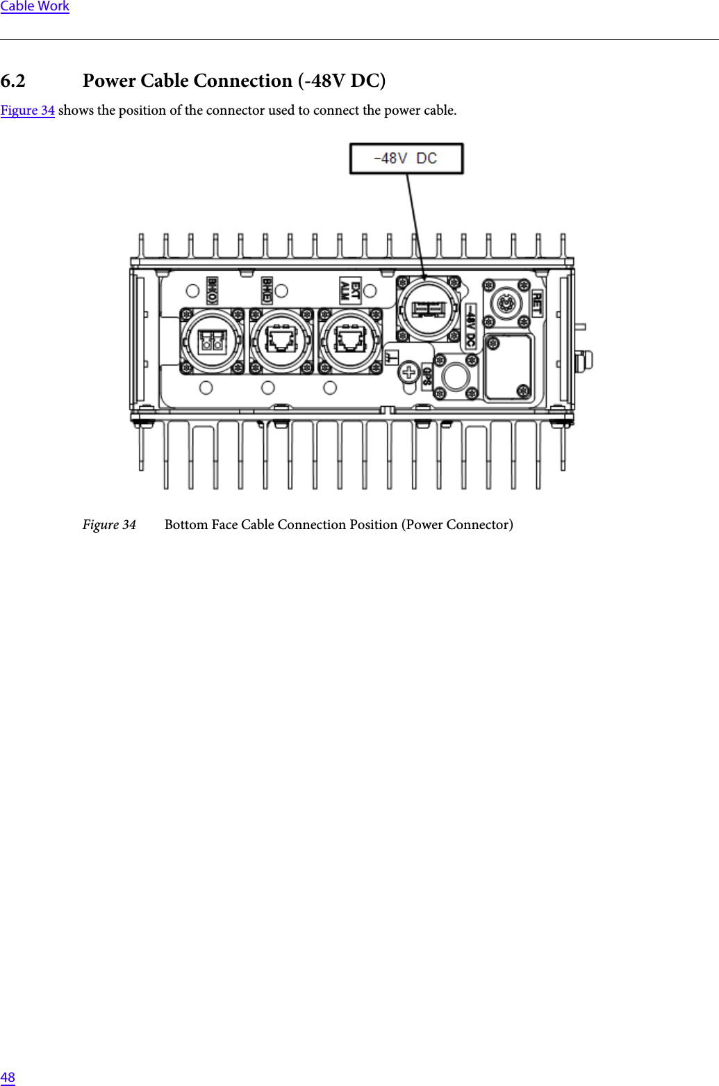
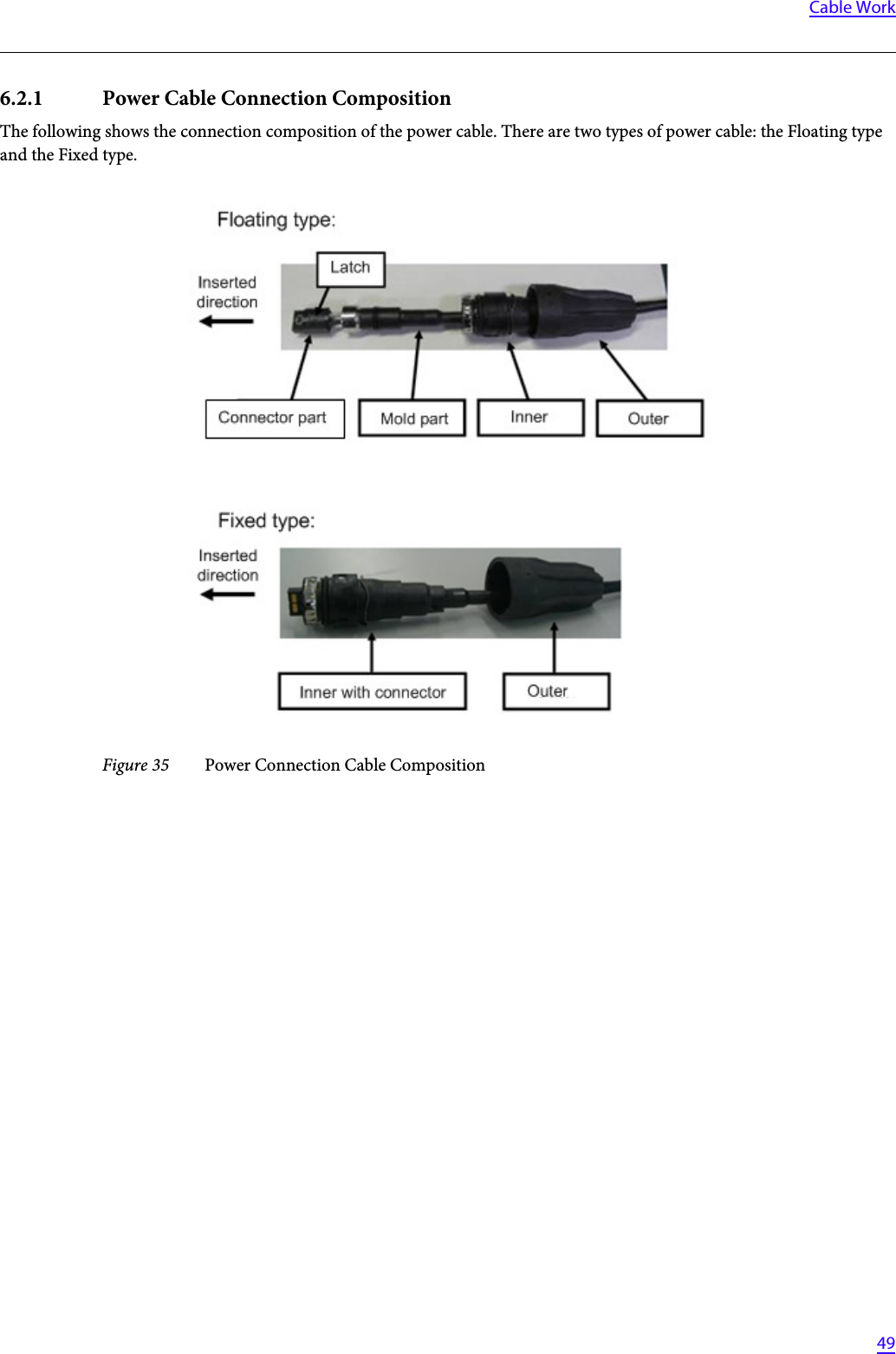
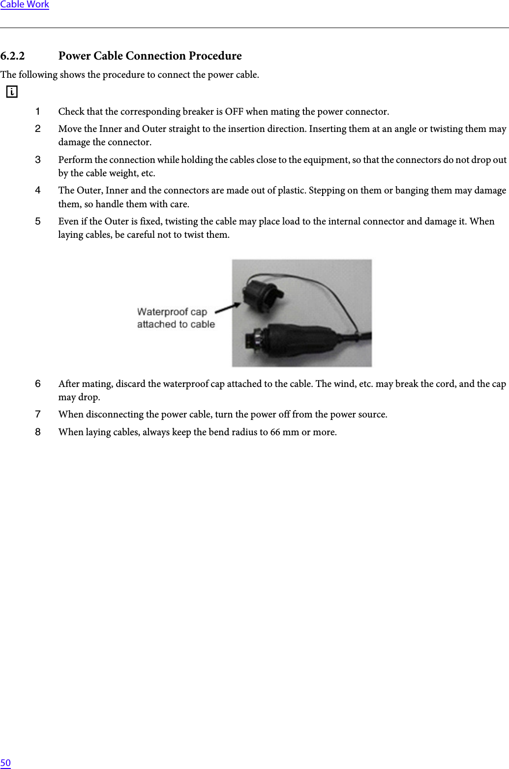
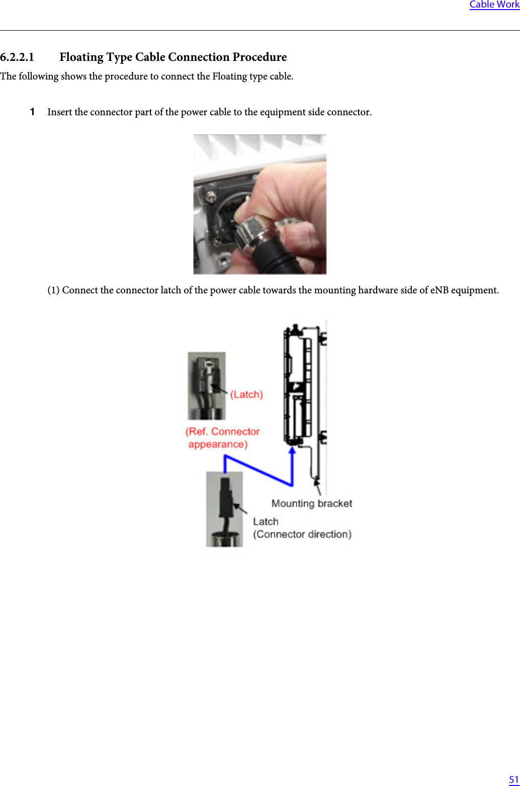
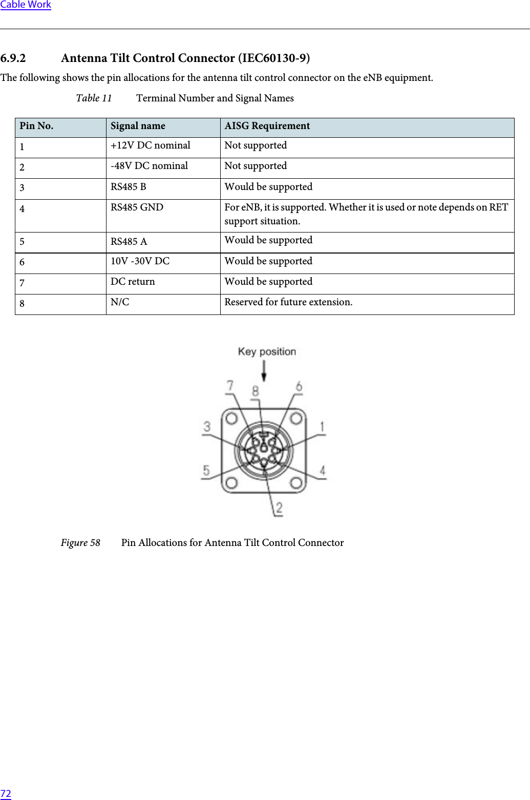
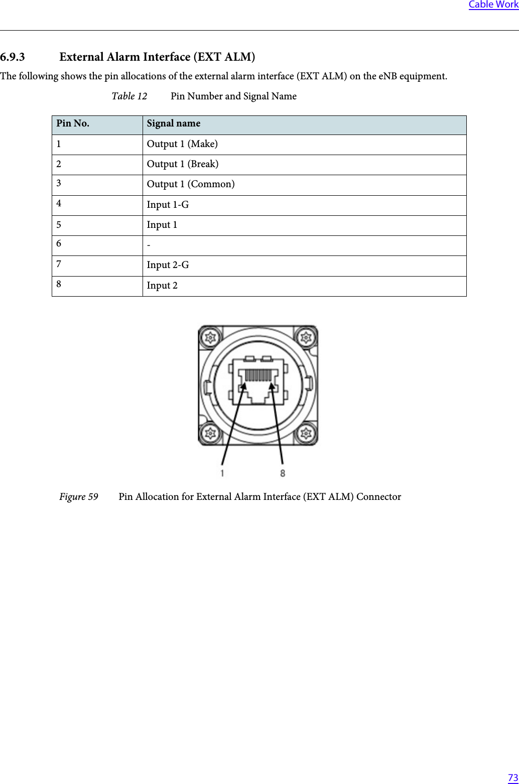
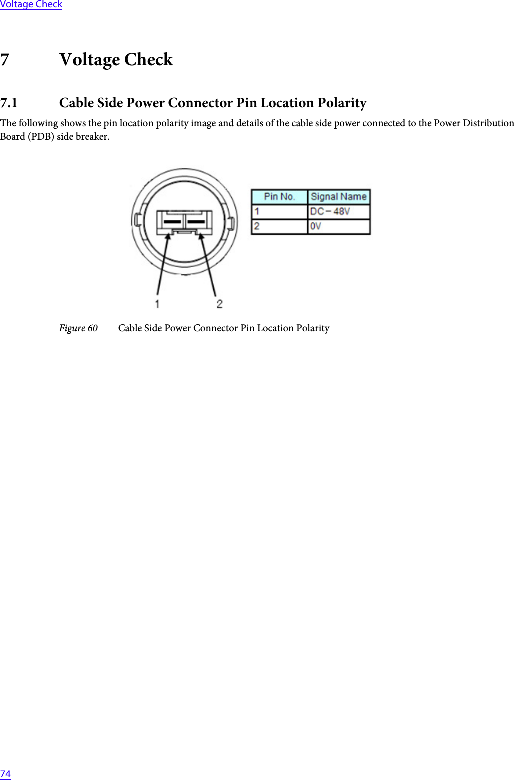
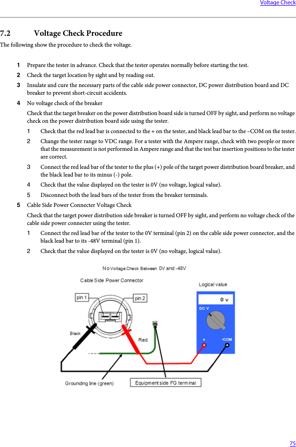
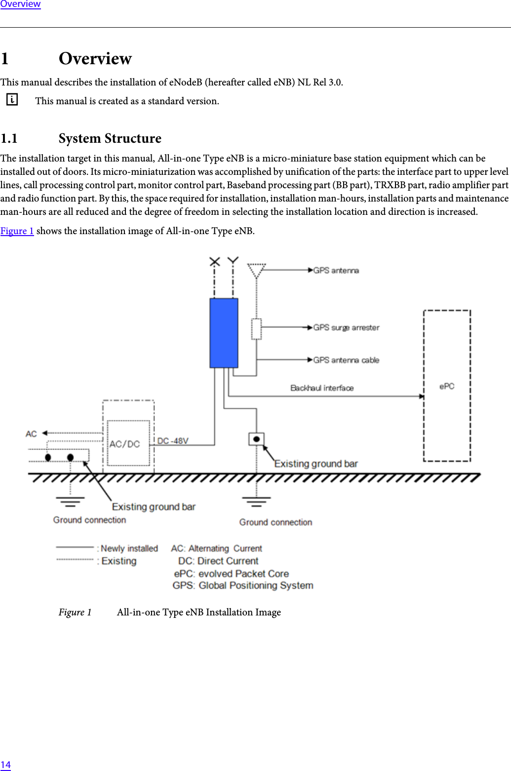
![4PrefacePrefacePurpose of This ManualThis manual describes the required knowledge and procedure to install the LTE system (eNodeB, hereafter referred to as eNB).GThis manual targets the 700MHz All-in-one Type eNB.Target ReaderThis manual is intended for the LTE system installation personnel and operation and maintenance personnel of a network operator.Manual Structure•Section 1 OverviewDescribes the system structure, equipment names and the main specification of the equipment.•Section 2 Equipment AppearanceShows the appearance of eNB equipment and its dimensions.•Section 3 Equipment Installation ConditionsShows the required space to install eNB equipment.•Section 4 Interface ConditionsShows the cable connection system diagram and eNB equipment interface.•Section 5 InstallationDescribes the cautions when carrying the equipment and the procedure to install eNB equipment.•Section 6 Cable WorkDescribes the procedure to work on various types of cables.•Section 7 Voltage CheckDescribes the procedure to check the voltage of the eNB equipment.Symbols Used in This ManualIn this manual, the following symbol is used to show notes. When reference to a note is required, it is expressed as "Refer to [i]."G CCC...CCC (CCC...CCC : note text)](https://usermanual.wiki/NEC/07208901/User-Guide-1768298-Page-4.png)
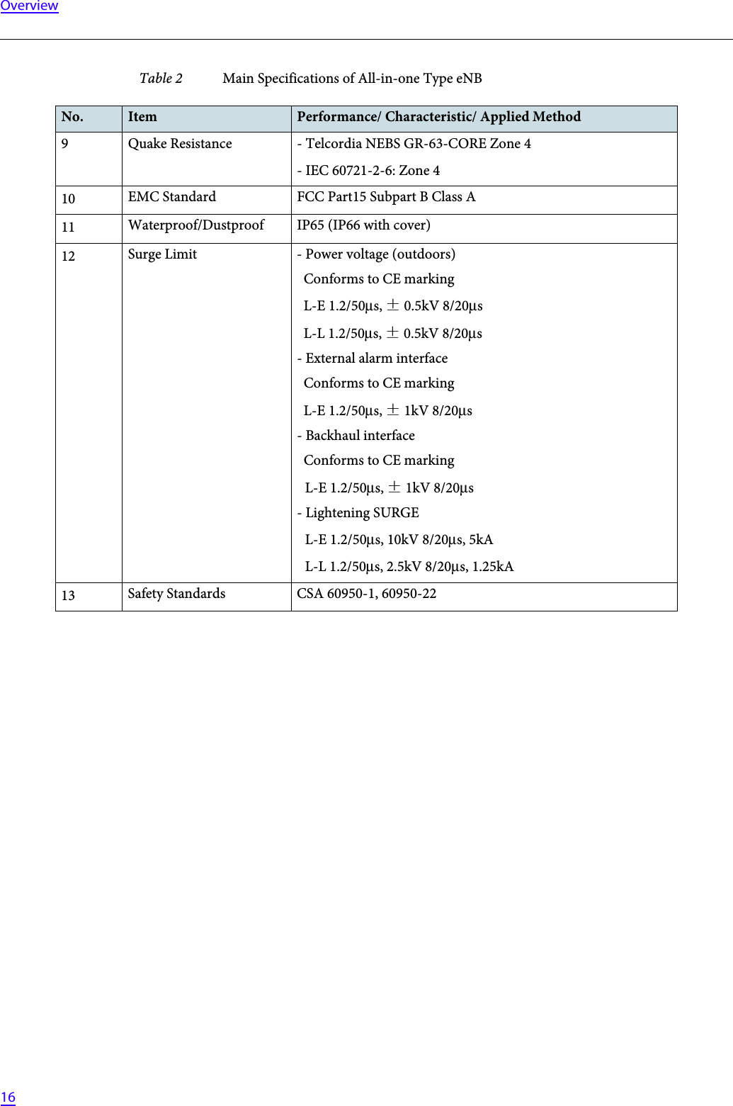
![15Overview1.2 Equipment NamesTable 1 shows the equipment type and displayed code applicable to this manual.1.3 Main SpecificationsTable 2 shows the main specifications of All-in-one Type eNB.Table 1 Equipment ListNo. Equipment Type Display Code Note1 Band 13: 700MHz MB4300-n313 Power source: DC -48VTransmission output: 5w x 2portsTable 2 Main Specifications of All-in-one Type eNBNo. Item Performance/ Characteristic/ Applied Method1Transmission/ Reception Frequency[DL] 746 - 756MHz[UL] 777 - 787MHz2Dimensions 251.0 ±2.5[mm](W)562.0 ±4.0[mm](H)149.0 ±2.5[mm](D)(Excluding protrusions)3Mass 17.0[kg]Excluding mounting hardware, F-COVER (Front Cover) and C-COVER (Connector Cover).4Power Specification DC-48 [V]: -43.2V to -57.0V5Rated current 7[A]6Maximum Power ConsumptionIncluding AISG consumption:206.6[W]Excluding AISG consumption:198.6[W]7Operation Environment TemperaturesVertical setup-33ºC to +50ºC (No sunlight)-33ºC to +45ºC (With sunlight)Horizontal setup-33ºC to +45ºC (No sunlight)-33ºC to +40ºC (With sunlight)The above temperature limits of operation environment drops by 2.5ºC for every 1km of altitude rise.8Relative Humidity 5% - 95%](https://usermanual.wiki/NEC/07208901/User-Guide-1768298-Page-15.png)