NEC 07208901 LTE Base Station User Manual Installation Guide
NEC Corporation LTE Base Station Installation Guide
NEC >
Installation Guide

1
imnenb_LR3.0
LTE
Installation Manual
eNB
MB-14310050-001(E)-01
March, 2012

2
Copyright © 2012 by NEC Corporation
This document describes the current planned product and feature description and release. However, the
specifications, configuration and the release plan contained in this document are subject to change without any
notice due to NEC's continuing design improvement.
All rights reserved. No part of this publication may be reproduced, transmitted, transcribed, stored in a retrieval
system, or translated in any form for by any means without the written permission of NEC Corporation.
All designations used in this document can be trademarks, the use of which by third parties for their own
purposes violates the rights of their owners.
Printed in Japan

3
Revision History
Revision History
Issue Date Revision Description Author Approval Remarks
1.0 March 30, 2012 1st release T.Araki K. Yoshida

4
Preface
Preface
Purpose of This Manual
This manual describes the required knowledge and procedure to install the LTE system (eNodeB, hereafter referred to as
eNB).
GThis manual targets the 700MHz All-in-one Type eNB.
Target Reader
This manual is intended for the LTE system installation personnel and operation and maintenance personnel of a network
operator.
Manual Structure
•Section 1 Overview
Describes the system structure, equipment names and the main specification of the equipment.
•Section 2 Equipment Appearance
Shows the appearance of eNB equipment and its dimensions.
•Section 3 Equipment Installation Conditions
Shows the required space to install eNB equipment.
•Section 4 Interface Conditions
Shows the cable connection system diagram and eNB equipment interface.
•Section 5 Installation
Describes the cautions when carrying the equipment and the procedure to install eNB equipment.
•Section 6 Cable Work
Describes the procedure to work on various types of cables.
•Section 7 Voltage Check
Describes the procedure to check the voltage of the eNB equipment.
Symbols Used in This Manual
In this manual, the following symbol is used to show notes. When reference to a note is required, it is expressed as "Refer to
[i]."
G CCC...CCC (CCC...CCC : note text)

5
Precautions
Precautions
The alert labels in this manual and attached to the eNB equipment body indicates the items you must follow to prevent
potential injury and safety hazard to you and other people, and perform the operation safely. Please read this manual
thoroughly before starting any operations.
Also, this manual must be kept in a safe place, so that you can read it whenever required.
When alert labels are directly attached to the equipment, always read the content.
This manual is intended for the LTE system installation personnel and operation and maintenance personnel of a network
operator.
Safety Instructions
The "Safety Instructions" provides safety instructions for the LTE system installation operations. For other items, read the
equipment manuals.
Definitions of Alert Categories
The following symbols categorize the dangers and level of damage that occurs when the content is ignored or wrong
procedure was performed.
!
DANGER:
This symbol indicates that there is explicit life-threatening danger that may cause death or
serious injuries if this item is ignored and the equipment is handled wrongly.
!
WARNING:
This symbol indicates that it may cause death or serious injuries if this item is ignored and the
equipment is handled wrongly.
!
CAUTION:
This symbol indicates that it may cause injuries and physical damage if this item is ignored and
the equipment is handled wrongly.
6
Precautions
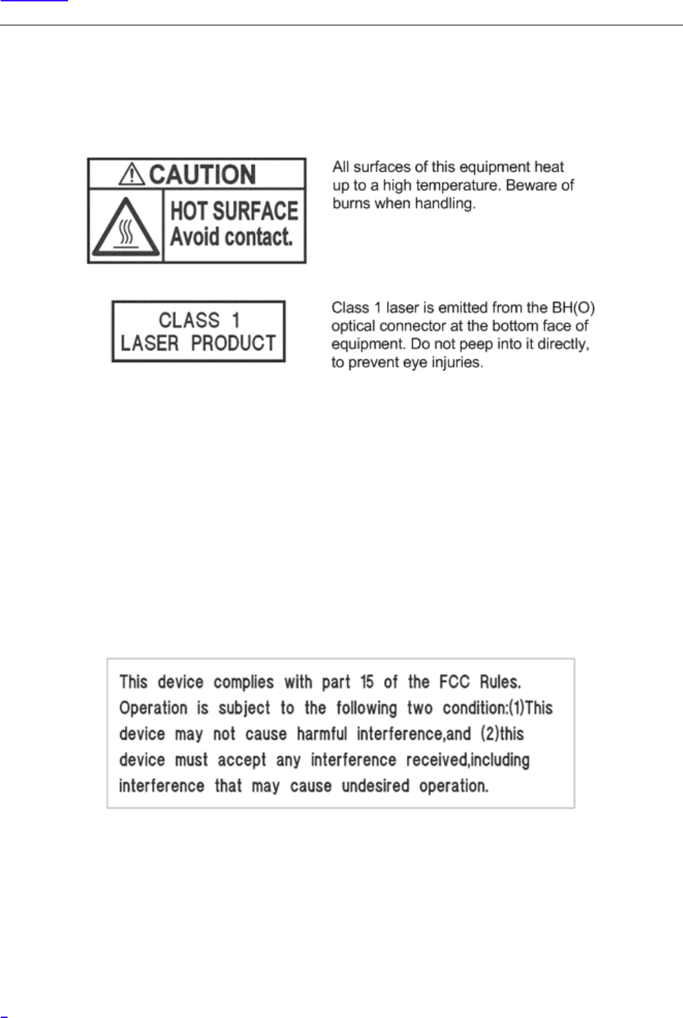
Alert Labels
The following shows the alert labels attached to the equipment. If an alert label is attached, always follow the instruction
written on the label.
Federal Communications Commission
Changes or modifications not expressly approved by NEC Corporation could void the users authority to operate the
equipment. (Section 15.21)
Section 15.105 (a) Class A Warning Label
NOTE: This equipment has been tested and found to comply with the limits for a Class A digital device, pursuant to part 15
of the FCC Rules. These limits are designed to provide reasonable protection against harmful interference when the
equipment is operated in a commercial environment. This equipment generates, uses, and can radiate radio frequency energy
and, if not installed and used in accordance with the instruction manual, may cause harmful interference to radio
communications. Operation of this equipment in a residential area is likely to cause harmful interference in which case the
user will be required to correct the interference at his own expense.
About the Safety Instructions
When you find a safety instruction in this manual, be sure to read the instruction before starting the work.
The following safety instructions, especially regarding items that may cause death or injury to you and other people in this
manual are listed by their alert categories.

7
Precautions
Alert Category: CAUTION
!
CAUTION:
About the Work in General
•Before starting the work, check the area of evacuation at the time of disaster.
•Do not work wearing slippers. They may cause injury by falling, etc.
•Be careful not to stumble over cables, parts and tools while working. It may cause
injuries and accidents.
•Be careful not to get the sleeves and hems of the working clothes caught. It may
cause injuries and accidents.
•Do not place liquid such as water into the equipment, and do not touch the
equipment with wet hands. Moisture in the equipment may cause electrocution
and equipment failure. In case liquid gets into the equipment, turn off the
equipment power and request repair.
• Do not dismantle or alter the equipment. It may cause electrocution, fire and
equipment failure.
•When installing or removing the equipment, cure the floor surface of the installed
location to prevent damage by dropping parts.
About Handling the eNB Equipment and SFP
•When handling eNB equipment itself and SFP, wear globes (thin cotton gloves).
Working with bare hands may cause burns, injury and accidents.
•Use correctly the parts for testing such as SFP, tester and cable referring to their
user manuals.
•When handling the eNB equipment and the SFP, wear a wrist band as an antistatic
measure. If you do not take any antistatic measures, the static electricity may
damage the equipment and the SFP.
About Handling High Voltage/ High Current
•Only the installation worker can touch the eNB equipment . Inside eNB
equipment, there are high voltage/ high currents flows, and they may cause
accidents.
•Always perform ground connection. Not following this instruction would cause
system failure by lightening and electrocution.
•When measuring voltage/ current, take appropriate insulating measures such as
covering the measurement terminal and the unused tool parts with insulating
tapes. Contact of measurement terminal and other terminals, or short-circuit by
tools may cause electrocution and accidents.
8
Precautions
Notes on Running the System
In "Notes on Running the System", the notes to protect the equipment from failure are described. To run the system normally,
follow the notes to operate.
Environment Conditions on Running the System
The following shows the usage conditions of eNB equipment. To run the system normally, consider the following items
during installation operation.
Category Details
Installation Install in a limited access area.
Temperature and
humidity
- Do not ventilate outside air.
- Refer to the following and check that the temperature and humidity
are appropriate. Also, check that there is no condensation.
Vertical Setup
-33ºC to +50ºC (No sunlight)
-33ºC to +45ºC (With sunlight)
Horizontal setup
-33ºC to +45ºC (No sunlight)
-33ºC to +40ºC (With sunlight)
The above temperature limits of operation environment drops by
2.5ºC for every 1km of altitude rise.
Liquid - Do not place liquid such as water and oil near eNodeB.
Vibration eNodeB is a precision instrument, so do not expose to vibration of
standard level (Telcordia NEBS GR-63-CORE Zone4) or more.
Heat dissipation - Natural cooling of eNB satisfies all the environmental conditions.
- To gain the expected heat dissipation, eNB has a radiator for natural
cooling on its surface. Natural cooling radiator, for its physical
characteristic, must be set up so that the fin part is vertical or
horizontal.
- No cooling method such as cooling by fans is used for eNodeB.
- There is no periodic replacement parts such as air filters.
- No always-driving part such as a fan is used for eNodeB.

9
Precautions
Notes on Running the System in General
•Before installing the equipment, remove all connector caps attached to the equipment side external interface connectors
to which external cables are planned to be connected.
Removing the connector caps, etc. in a high place may result in the connector caps dropping.
- If external cables are not connected right after equipment installation, place outdoor weather resistant tapes on the
temporary connector caps as waterproof treatment.
•In case you touch the equipment for maintenance, there may be places on the equipment reaching high temperature.
Wear protection such as gloves when handling the equipment.
•Do not allow foreign objects such as screws, wire rods and metal scraps inside the eNB Equipment. They may cause eNB
equipment failure by equipment damage and short-circuit.
•Wear antistatic shoes while working.
•When working after rain, wipe the water drops on the equipment before opening the maintenance window.
10
Precautions
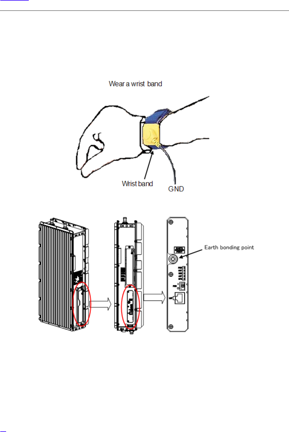
Notes on Handling the eNB Equipment and SFP
•To prevent static electricity, always wear globes (thin cotton gloves) and a wrist band as antistatic measures when
working on the eNB equipment, inserting or removing SFP into/from the equipment.
By static electricity the electrical parts of the equipment or the SFP may be damaged. The grounding terminal of the wrist
band is connected to the earth bonding point in the maintenance window of the equipment.

11
Precautions
Notes on Handling the Power
•Do not turn the power ON/ OFF unless required.
Notes on Handling the Cables and Connectors
•Do not swing or bend the cable with force. It may cause the cable to break or damage the connector.
•Do not remove the optical connector cap unless connecting the connector. If the optical connector is damaged or gets
dust on it, it may cause communication failure.
•Use the tools and parts such as cables correctly, referring to their user manuals.
•Tie the external cables without putting stress, meaning without twisting and pulling on the equipment connector part.
•When removing the connector or the waterproof cap to mate again, clean the mating parts.
•Depending on the environment condition, the FullAXS connector surface may become rough, and touching it by bare
hands may cause the plastic toughening agent to irritate the skin. If the toughening agent gets on to your skin, wash it
thoroughly.

12
Table of Content
Table of Content
Revision History . . . . . . . . . . . . . . . . . . . . . . . . . . . . . . . . . . . . . . . . . . . . . . . . . . . . . . . . . . . . . . . . . . . . . . 3
Preface . . . . . . . . . . . . . . . . . . . . . . . . . . . . . . . . . . . . . . . . . . . . . . . . . . . . . . . . . . . . . . . . . . . . . . . . . . . . . . . 4
Precautions. . . . . . . . . . . . . . . . . . . . . . . . . . . . . . . . . . . . . . . . . . . . . . . . . . . . . . . . . . . . . . . . . . . . . . . . . . . 5
1 Overview . . . . . . . . . . . . . . . . . . . . . . . . . . . . . . . . . . . . . . . . . . . . . . . . . . . . . . . . . . . . . . . . . . . . . . . . . . . .14
1.1 System Structure . . . . . . . . . . . . . . . . . . . . . . . . . . . . . . . . . . . . . . . . . . . . . . . . . . . . . . . . . . . . . . . . . . . .14
1.2 Equipment Names . . . . . . . . . . . . . . . . . . . . . . . . . . . . . . . . . . . . . . . . . . . . . . . . . . . . . . . . . . . . . . . . . . . 15
1.3 Main Specifications . . . . . . . . . . . . . . . . . . . . . . . . . . . . . . . . . . . . . . . . . . . . . . . . . . . . . . . . . . . . . . . . . .15
2 Equipment Appearance. . . . . . . . . . . . . . . . . . . . . . . . . . . . . . . . . . . . . . . . . . . . . . . . . . . . . . . . . . . . . .17
3 Equipment Installation Conditions . . . . . . . . . . . . . . . . . . . . . . . . . . . . . . . . . . . . . . . . . . . . . . . . . . . 19
4 Interface Conditions . . . . . . . . . . . . . . . . . . . . . . . . . . . . . . . . . . . . . . . . . . . . . . . . . . . . . . . . . . . . . . . . .20
4.1 Cable Connection System Diagram. . . . . . . . . . . . . . . . . . . . . . . . . . . . . . . . . . . . . . . . . . . . . . . . . . .20
4.2 External Interface . . . . . . . . . . . . . . . . . . . . . . . . . . . . . . . . . . . . . . . . . . . . . . . . . . . . . . . . . . . . . . . . . . . . 22
4.2.1 Bottom Face External Interface Locations/ Names and Interface Details. . . . . . . . . . . . . . . . 22
4.2.2 Top Face External Interface Locations/ Names and Details. . . . . . . . . . . . . . . . . . . . . . . . . . . . . 23
4.2.3 Maintenance Window Interface Locations/ Names and Details . . . . . . . . . . . . . . . . . . . . . . . . 24
5 Equipment Installation. . . . . . . . . . . . . . . . . . . . . . . . . . . . . . . . . . . . . . . . . . . . . . . . . . . . . . . . . . . . . . . 25
5.1 Cautions on Carrying the Equipment . . . . . . . . . . . . . . . . . . . . . . . . . . . . . . . . . . . . . . . . . . . . . . . . .25
5.1.1 Temporary Placement of Equipment . . . . . . . . . . . . . . . . . . . . . . . . . . . . . . . . . . . . . . . . . . . . . . . . . 25
5.1.2 Carrying the Equipment by the Handles . . . . . . . . . . . . . . . . . . . . . . . . . . . . . . . . . . . . . . . . . . . . . . 26
5.1.3 Carrying Equipment by Hoisting Up/ Down. . . . . . . . . . . . . . . . . . . . . . . . . . . . . . . . . . . . . . . . . . .27
5.2 Equipment Installation Forms . . . . . . . . . . . . . . . . . . . . . . . . . . . . . . . . . . . . . . . . . . . . . . . . . . . . . . . .29
5.2.1 Installation Examples of Ladder/ Wall/ Pole/ Cross arm/ Suspension Mount . . . . . . . . . . . . 29
5.3 Ladder/ Wall/ Pole/ Cross Arm/ Suspension Installation . . . . . . . . . . . . . . . . . . . . . . . . . . . . . . . 31
5.3.1 Dedicated Mounting Hardware for Installation. . . . . . . . . . . . . . . . . . . . . . . . . . . . . . . . . . . . . . . .31
5.3.2 Installation Method . . . . . . . . . . . . . . . . . . . . . . . . . . . . . . . . . . . . . . . . . . . . . . . . . . . . . . . . . . . . . . . . . .32
5.3.3 Installation Procedure . . . . . . . . . . . . . . . . . . . . . . . . . . . . . . . . . . . . . . . . . . . . . . . . . . . . . . . . . . . . . . .35
5.3.4 C-COVER (Connector Cover) Installation Procedure . . . . . . . . . . . . . . . . . . . . . . . . . . . . . . . . . . . 39
5.3.5 F-COVER (Front Cover) Installation Procedure. . . . . . . . . . . . . . . . . . . . . . . . . . . . . . . . . . . . . . . . . 43
5.4 List of Attachments and Tools . . . . . . . . . . . . . . . . . . . . . . . . . . . . . . . . . . . . . . . . . . . . . . . . . . . . . . . . 45
6 Cable Work . . . . . . . . . . . . . . . . . . . . . . . . . . . . . . . . . . . . . . . . . . . . . . . . . . . . . . . . . . . . . . . . . . . . . . . . . .46
6.1 List of Used Cables and Connectors . . . . . . . . . . . . . . . . . . . . . . . . . . . . . . . . . . . . . . . . . . . . . . . . . . 46
6.2 Power Cable Connection (-48V DC) . . . . . . . . . . . . . . . . . . . . . . . . . . . . . . . . . . . . . . . . . . . . . . . . . . . 48
6.2.1 Power Cable Connection Composition . . . . . . . . . . . . . . . . . . . . . . . . . . . . . . . . . . . . . . . . . . . . . . . 49
6.2.2 Power Cable Connection Procedure . . . . . . . . . . . . . . . . . . . . . . . . . . . . . . . . . . . . . . . . . . . . . . . . . . 50
6.2.2.1 Floating Type Cable Connection Procedure. . . . . . . . . . . . . . . . . . . . . . . . . . . . . . . . . . . . . . . . . . . 51
6.2.2.2 Fixed Type Cable Connection Procedure. . . . . . . . . . . . . . . . . . . . . . . . . . . . . . . . . . . . . . . . . . . . . .54
6.3 Backhaul Cable Connection . . . . . . . . . . . . . . . . . . . . . . . . . . . . . . . . . . . . . . . . . . . . . . . . . . . . . . . . . .55
6.3.1 Metal Type Backhaul Cable Connection (BH(E)) . . . . . . . . . . . . . . . . . . . . . . . . . . . . . . . . . . . . . . . 55
6.3.1.1 Backhaul Cable Connection Procedure (Electrical) . . . . . . . . . . . . . . . . . . . . . . . . . . . . . . . . . . . . 56
6.3.2 Optical Type Backhaul Cable Connection (BH(O)) . . . . . . . . . . . . . . . . . . . . . . . . . . . . . . . . . . . . . 58
6.3.2.1 Backhaul Cable Connection Procedure (Optical) . . . . . . . . . . . . . . . . . . . . . . . . . . . . . . . . . . . . . .59
6.3.3 Notes on Handling Optical Cables . . . . . . . . . . . . . . . . . . . . . . . . . . . . . . . . . . . . . . . . . . . . . . . . . . . .61

13
Table of Content
6.4 GPS Cable Connection (GPS) . . . . . . . . . . . . . . . . . . . . . . . . . . . . . . . . . . . . . . . . . . . . . . . . . . . . . . . . . 62
6.4.1 GPS Cable Connection Procedure . . . . . . . . . . . . . . . . . . . . . . . . . . . . . . . . . . . . . . . . . . . . . . . . . . . . 62
6.5 External Alarm Interface Cable Connection (EXT ALM) . . . . . . . . . . . . . . . . . . . . . . . . . . . . . . . . 64
6.5.1 External Alarm Interface Cable Connection Procedure (EXT ALM) . . . . . . . . . . . . . . . . . . . . . 64
6.6 FG Cable Connection (FG) . . . . . . . . . . . . . . . . . . . . . . . . . . . . . . . . . . . . . . . . . . . . . . . . . . . . . . . . . . . 65
6.6.1 FG Cable Connection Procedure . . . . . . . . . . . . . . . . . . . . . . . . . . . . . . . . . . . . . . . . . . . . . . . . . . . . . 65
6.7 Antenna Tilt Control Cable Connection (RET) . . . . . . . . . . . . . . . . . . . . . . . . . . . . . . . . . . . . . . . . . 67
6.7.1 Antenna Tilt Control (RET) Cable Connection Procedure . . . . . . . . . . . . . . . . . . . . . . . . . . . . . . 67
6.8 Antenna Cable Connection (ANT0/ANT1) . . . . . . . . . . . . . . . . . . . . . . . . . . . . . . . . . . . . . . . . . . . . 69
6.8.1 Antenna Cable Connection Procedure (ANT0/ANT1). . . . . . . . . . . . . . . . . . . . . . . . . . . . . . . . . . 69
6.9 Connector Details . . . . . . . . . . . . . . . . . . . . . . . . . . . . . . . . . . . . . . . . . . . . . . . . . . . . . . . . . . . . . . . . . . . 71
6.9.1 Power Connector Pin Allocation . . . . . . . . . . . . . . . . . . . . . . . . . . . . . . . . . . . . . . . . . . . . . . . . . . . . . 71
6.9.2 Antenna Tilt Control Connector (IEC60130-9). . . . . . . . . . . . . . . . . . . . . . . . . . . . . . . . . . . . . . . . . 72
6.9.3 External Alarm Interface (EXT ALM) . . . . . . . . . . . . . . . . . . . . . . . . . . . . . . . . . . . . . . . . . . . . . . . . . . 73
7 Voltage Check. . . . . . . . . . . . . . . . . . . . . . . . . . . . . . . . . . . . . . . . . . . . . . . . . . . . . . . . . . . . . . . . . . . . . . . 74
7.1 Cable Side Power Connector Pin Location Polarity . . . . . . . . . . . . . . . . . . . . . . . . . . . . . . . . . . . . 74
7.2 Voltage Check Procedure . . . . . . . . . . . . . . . . . . . . . . . . . . . . . . . . . . . . . . . . . . . . . . . . . . . . . . . . . . . . 75
14
Overview
1Overview
This manual describes the installation of eNodeB (hereafter called eNB) NL Rel 3.0.
GThis manual is created as a standard version.
1.1 System Structure
The installation target in this manual, All-in-one Type eNB is a micro-miniature base station equipment which can be
installed out of doors. Its micro-miniaturization was accomplished by unification of the parts: the interface part to upper level
lines, call processing control part, monitor control part, Baseband processing part (BB part), TRXBB part, radio amplifier part
and radio function part. By this, the space required for installation, installation man-hours, installation parts and maintenance
man-hours are all reduced and the degree of freedom in selecting the installation location and direction is increased.
Figure 1 shows the installation image of All-in-one Type eNB.
Figure 1 All-in-one Type eNB Installation Image
15
Overview
1.2 Equipment Names
Table 1 shows the equipment type and displayed code applicable to this manual.
1.3 Main Specifications
Table 2 shows the main specifications of All-in-one Type eNB.
Table 1 Equipment List
No. Equipment Type Display Code Note
1 Band 13: 700MHz MB4300-n313 Power source: DC -48V
Transmission output: 5w x 2ports
Table 2 Main Specifications of All-in-one Type eNB
No. Item Performance/ Characteristic/ Applied Method
1Transmission/ Reception
Frequency
[DL] 746 - 756MHz
[UL] 777 - 787MHz
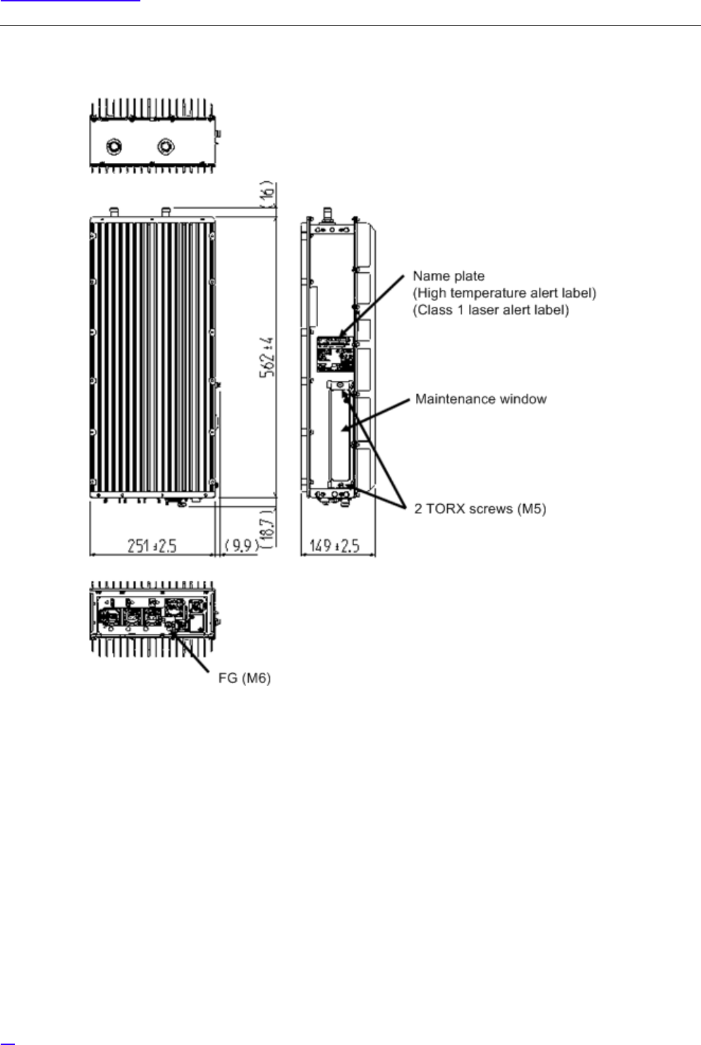
2Dimensions 251.0 ±2.5[mm](W)
562.0 ±4.0[mm](H)
149.0 ±2.5[mm](D)
(Excluding protrusions)
3Mass 17.0[kg]
Excluding mounting hardware, F-COVER (Front Cover) and C-
COVER (Connector Cover).
4Power Specification DC-48 [V]: -43.2V to -57.0V
5Rated current 7[A]
6Maximum Power
Consumption
Including AISG consumption:
206.6[W]
Excluding AISG consumption:
198.6[W]
7Operation Environment
Temperatures
Vertical setup
-33ºC to +50ºC (No sunlight)
-33ºC to +45ºC (With sunlight)
Horizontal setup
-33ºC to +45ºC (No sunlight)
-33ºC to +40ºC (With sunlight)
The above temperature limits of operation environment drops
by 2.5ºC for every 1km of altitude rise.
8Relative Humidity 5% - 95%

16
Overview
9 Quake Resistance - Telcordia NEBS GR-63-CORE Zone 4
- IEC 60721-2-6: Zone 4
10 EMC Standard FCC Part15 Subpart B Class A
11 Waterproof/Dustproof IP65 (IP66 with cover)
12 Surge Limit - Power voltage (outdoors)
Conforms to CE marking
L-E 1.2/50μs, ±0.5kV 8/20μs
L-L 1.2/50μs, ±0.5kV 8/20μs
- External alarm interface
Conforms to CE marking
L-E 1.2/50μs, ±1kV 8/20μs
- Backhaul interface
Conforms to CE marking
L-E 1.2/50μs, ±1kV 8/20μs
- Lightening SURGE
L-E 1.2/50μs, 10kV 8/20μs, 5kA
L-L 1.2/50μs, 2.5kV 8/20μs, 1.25kA
13 Safety Standards CSA 60950-1, 60950-22
Table 2 Main Specifications of All-in-one Type eNB
No. Item Performance/ Characteristic/ Applied Method
17
Equipment Appearance
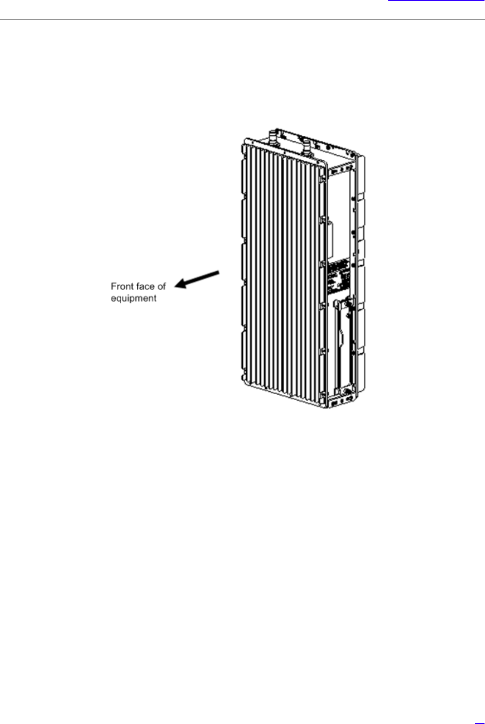
2 Equipment Appearance
The following shows the equipment appearance and equipment flat surface appearance of All-in-one Type eNB.
1Equipment Appearance
Figure 2 Equipment Appearance
18
Equipment Appearance
2Equipment Flat Face Appearance
Figure 3 Equipment Flat Face Appearance
19
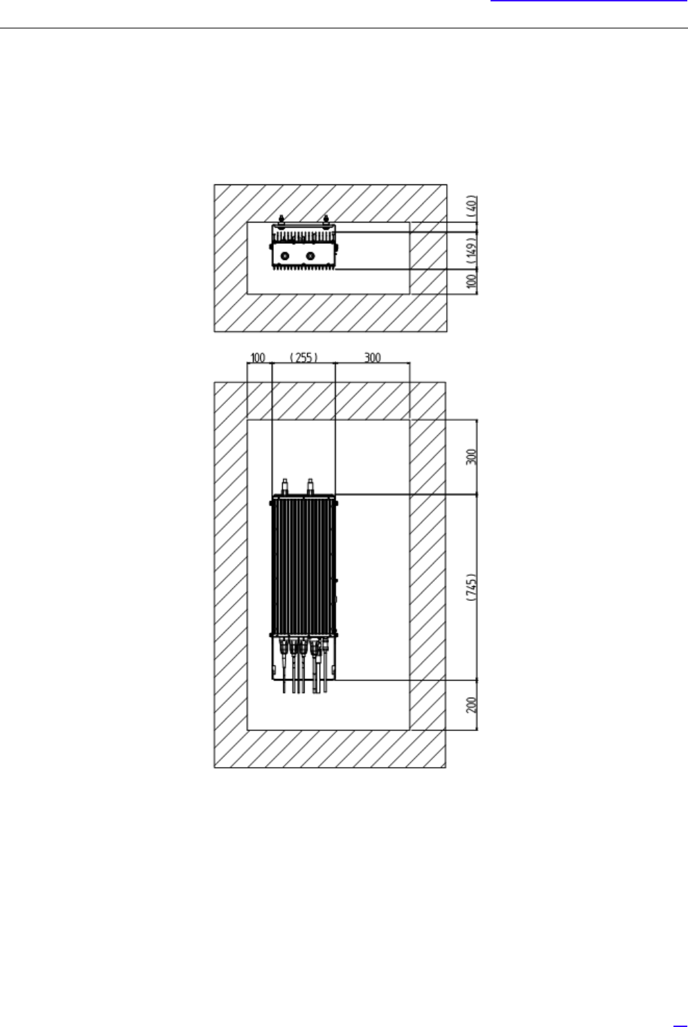
Equipment Installation Conditions
3 Equipment Installation Conditions
The following shows the clearance condition for single installation of All-in-one Type eNB. (In case of "Ladder mount/ wall
mount/ pole mount/ cross arm mount or suspension mount.)
Figure 4 Single Installation Clearance
G
1Make sure the temperature is 50ºC or lower at all the front, back, left and right sides.
2Make sure air ventilation is possible through the top face.
20
Interface Conditions
4 Interface Conditions
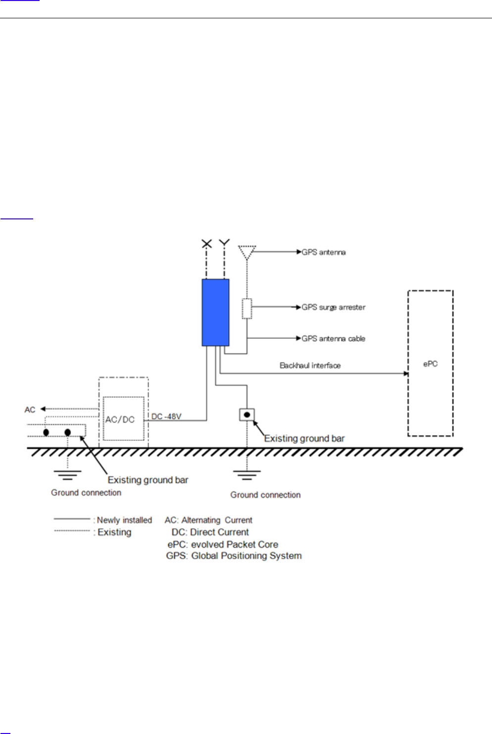
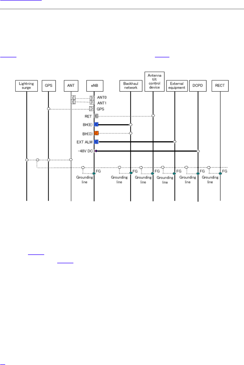
4.1 Cable Connection System Diagram
Figure 5 shows the cable connection system diagram for All-in-one Type eNB. Table 3 shows the list of connectors and
legends.
Figure 5 Cable Connection System Diagram
G
1Install dedicated power supply cable and breaker to the eNB equipment from the power source facility (DCPD).
Breaker would work as the equipment's breaker.
2Connector type on the backhaul network side depends on the remote equipment.
3Figure 5 omits ACPDB master, ACPDB, storage battery, UPS equipment, etc.
4Broken line in Figure 5 may change depending on installation contract, scope of work and installation design.
21
Interface Conditions
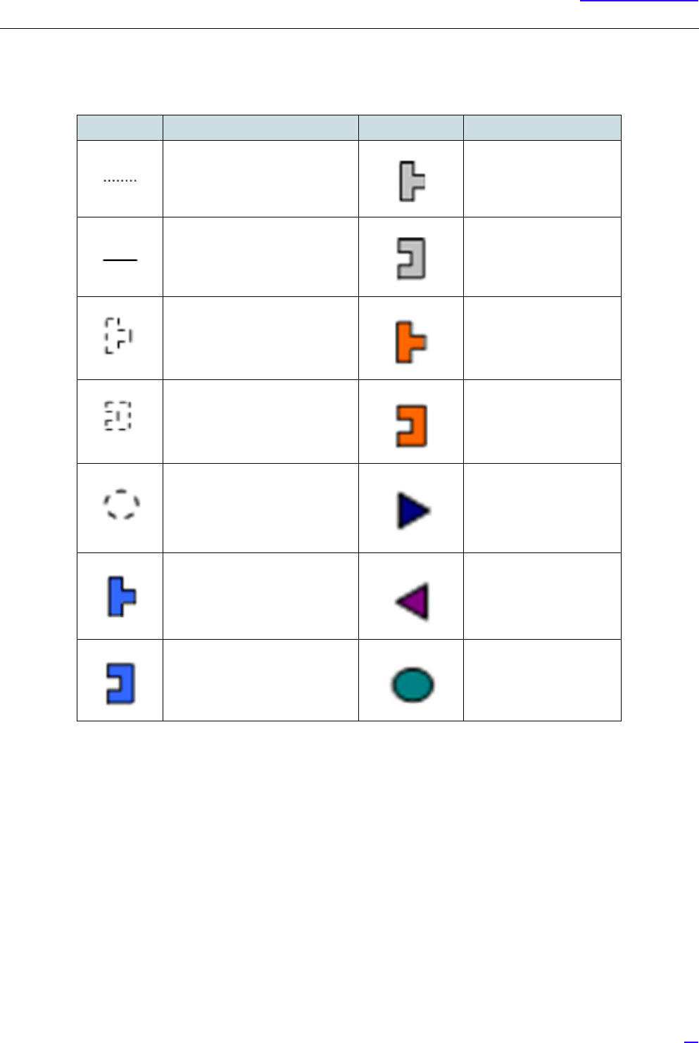
Table 3 Connector List/ Legend
Symbol Details Symbol Detail
Out of preparation range Round waterproof (P)
IEC60130-9
Attachment to equipment main
body/ installation cables
Round waterproof (J)
IEC60130-9
N type waterproof (P) Optical 2-core waterproof
boots (P)
N type waterproof (J) Optical 2-core waterproof
boots (J)
Out of preparation range, or
parts different by office
condition or design
Square waterproof boots
(P)
RJ-45+waterproof boots (P) Square waterproof boots
(J)
RJ-45+ waterproof boots (J) M6 crimping terminal
22
Interface Conditions
4.2 External Interface
The following shows the interface locations, names and details on bottom face, top face and maintenance window of All-in-
one Type eNB.
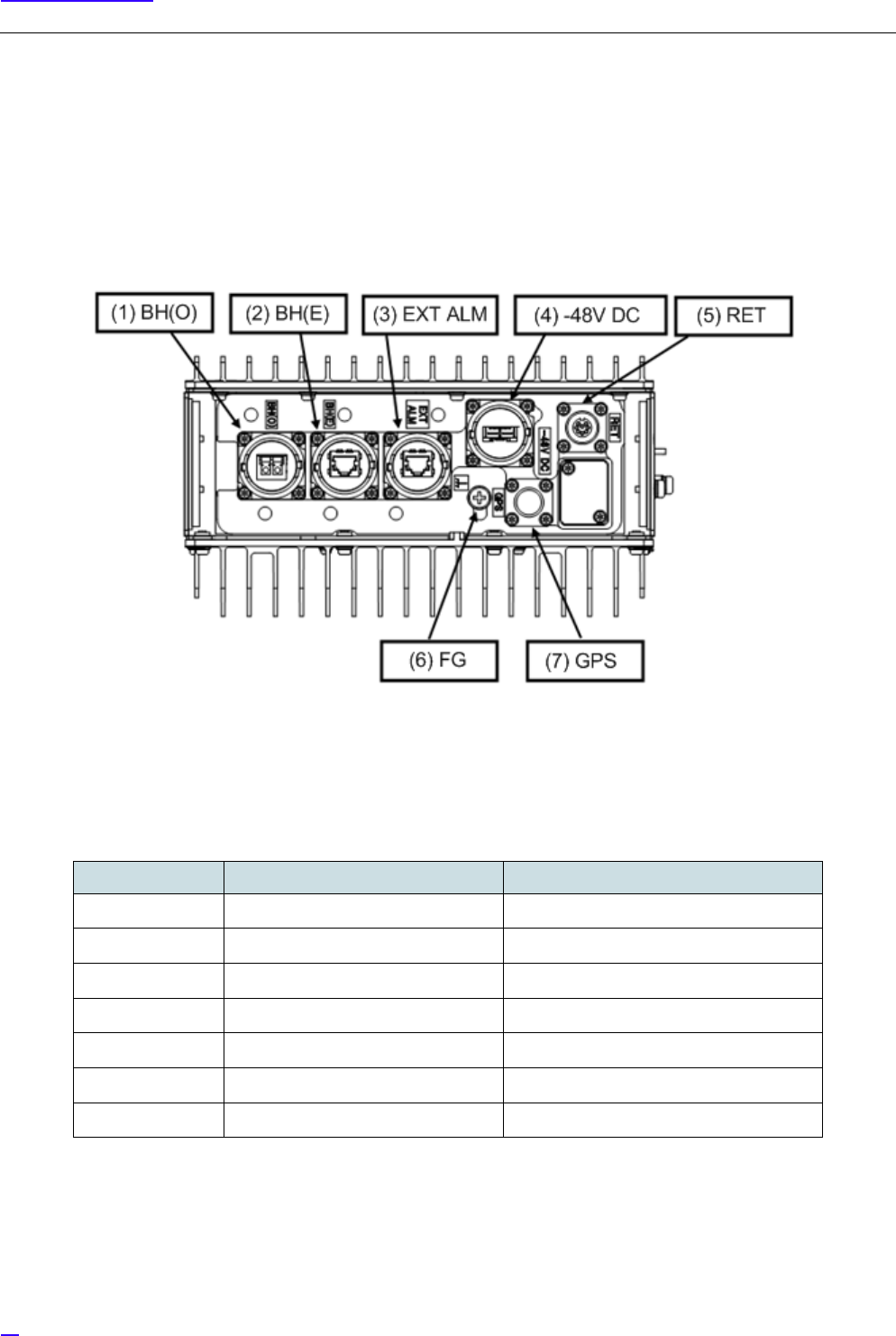
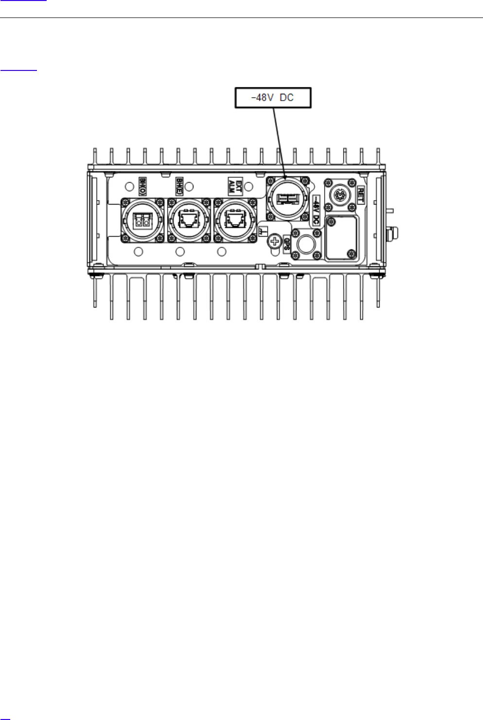
4.2.1 Bottom Face External Interface Locations/ Names and Interface Details
1Bottom Face External Interface Locations and Names
Figure 6 External Interface Locations and Names (Bottom Face)
2Interface Details
Table 4 External Interface Details (Bottom Face)
No. in Fig External Interface Label External Interface Name
(1) BH (O) Backhaul interface (Optical)
(2) BH (E) Backhaul interface (Electrical)
(3) EXT ALM External alarm interface
(4) -48V DC Power input interface
(5) RET Antenna tilt control interface
(6 FG Frame ground
(7) GPS L1 GPS interface
23
Interface Conditions
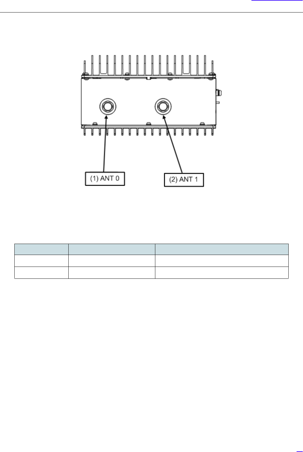
4.2.2 Top Face External Interface Locations/ Names and Details
1Top Face External Interface Locations and Names
Figure 7 External Interface Locations and Names (Top Face)
2Interface Details
Table 5 External Interface (Top Face)
No. in Fig External Interface Label External Interface Name
(1) ANT 0 RF antenna interface 0
(2) ANT 1 RF antenna interface 1
24
Interface Conditions
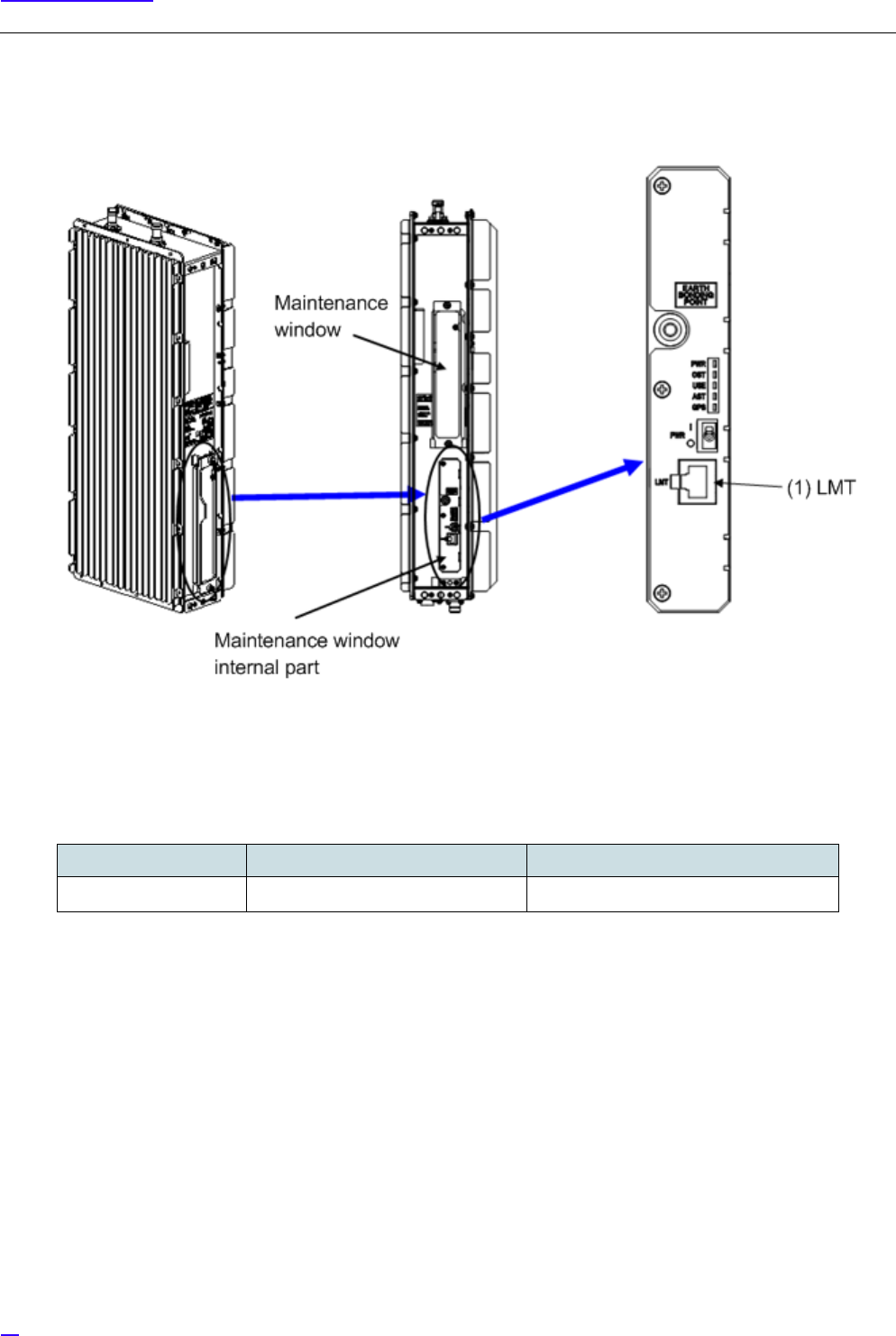
4.2.3 Maintenance Window Interface Locations/ Names and Details
1Maintenance Window Interface Locations and Names
Figure 8 Maintenance Window Image
2Interface Details
Table 6 Maintenance Window Interface Details
No. in Fig External Interface Label External Interface Name
(1) LMT LMT interface
25
Equipment Installation
5 Equipment Installation
This section shows the installation procedure of All-in-one Type eNB.
G
1Before installing the equipment, remove all connector caps attached to the equipment side external interface
connectors to which external cables are planned to be connected.
Removing the connector caps, etc. in a high place may result in the connector caps dropping.
2If external cables are not connected right after equipment installation, place outdoor weather resistant tapes on
the temporary connector caps as waterproof treatment.
5.1 Cautions on Carrying the Equipment
The following shows the cautions on when carrying the All-in-one Type eNB.
G
1Carrier of All-in-one Type eNB must wear working gloves and shoes.
2When carrying the equipment into the premise, perform required curing on the route.
3Carry the equipment in its package box to prevent damage while carrying.
4When the equipment goes through the inspection door, cure the opening to prevent damage to the building
and equipment.
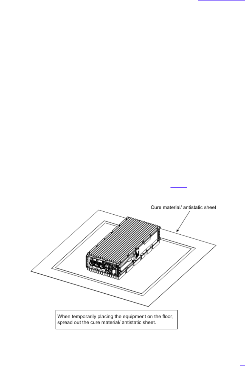
5.1.1 Temporary Placement of Equipment
If temporarily placing All-in-one Type eNB on the floor, place it carefully as shown in Figure 9 to prevent damage to
connectors and protrusions.
Figure 9 Temporary Placement Image
26
Equipment Installation
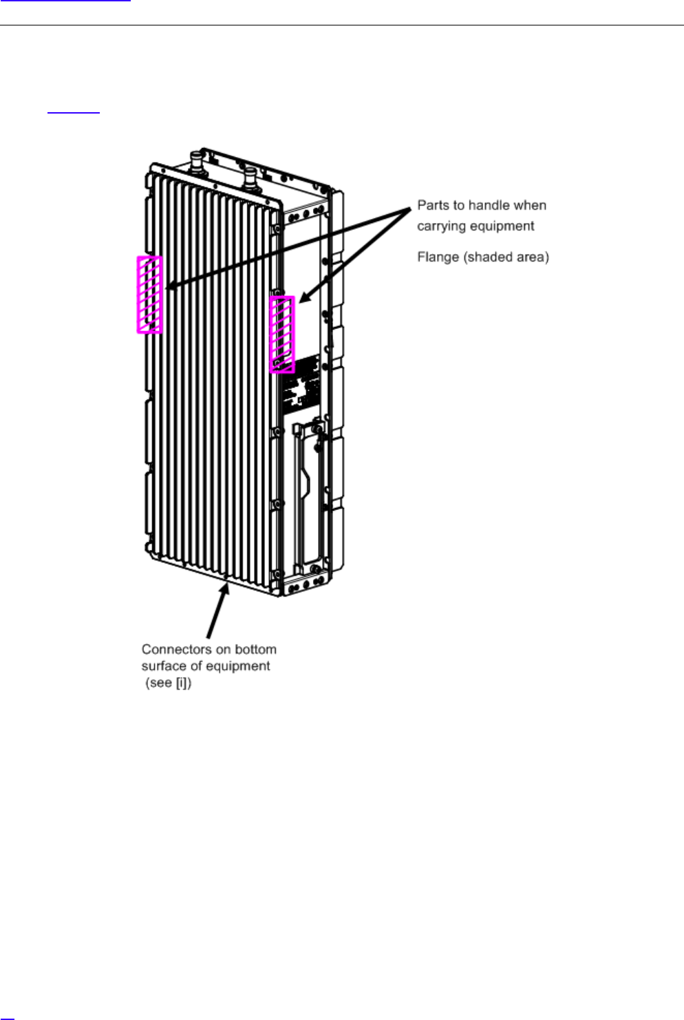
5.1.2 Carrying the Equipment by the Handles
When carrying All-in-one Type eNB, the flange part (shaded part) on both sides of the main body can be used as handles.
Refer to Figure 10.
Figure 10 Handling Parts Used for Carrying
GWhen handling the equipment, be careful not to damage the connectors on the bottom face of equipment.
If you place the equipment vertically on the floor, it may damage the connectors on the bottom face.
27
Equipment Installation
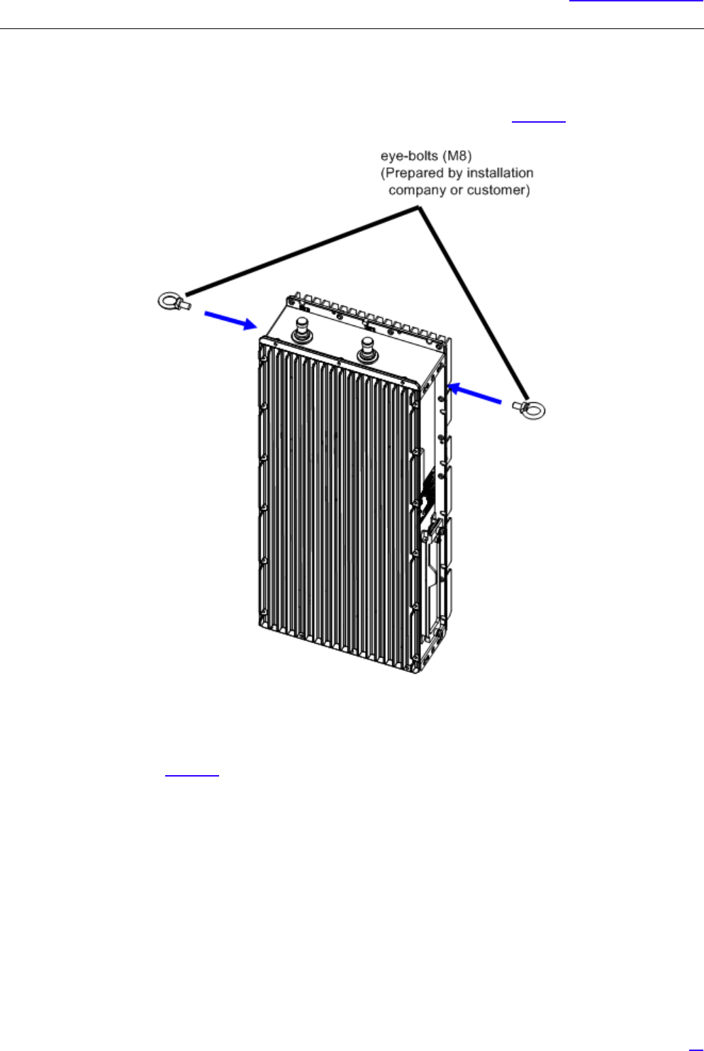
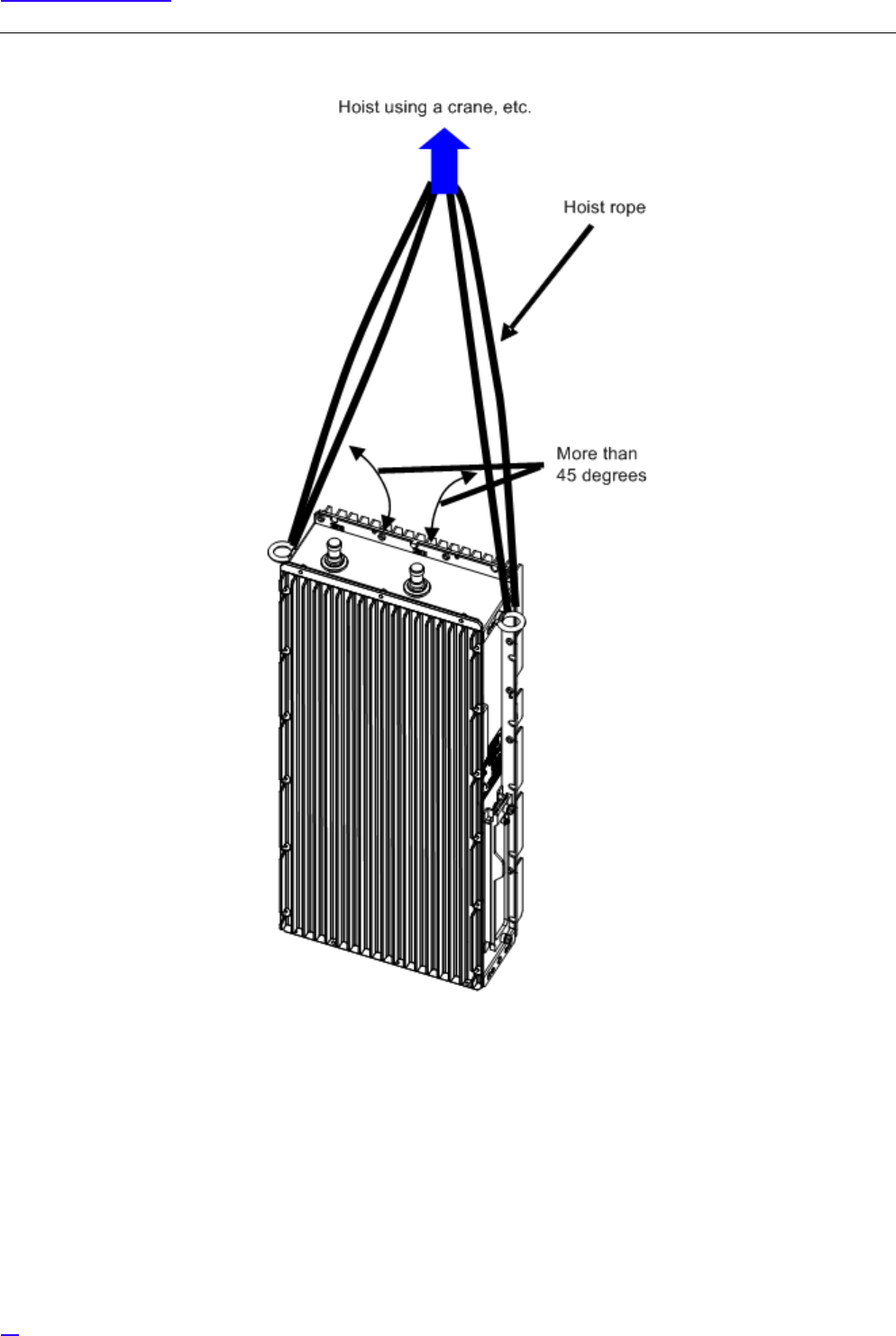
5.1.3 Carrying Equipment by Hoisting Up/ Down
When hoisting the equipment up/ down, use eye-bolts and follow the procedure below.
1Insert eye-bolts into the screw holes on the sides of the equipment as shown in Figure 11.
Figure 11 Attaching eye-bolts
2Hoist the equipment using a crane, etc. up to a higher place or down to a lower place by placing ropes in the eye-
bolts as shown in Figure 12.
3After carrying the equipment, remove the eye-bolts.
28
Equipment Installation
Figure 12 Hoist up/down Image
29
Equipment Installation
5.2 Equipment Installation Forms
All-in-one Type eNB has the following installation forms considering the ease of installation.
•Ladder mount/ Wall mount/ Pole mount
Vertical setup
•Cross arm mount/Suspension mount
Horizontal setup
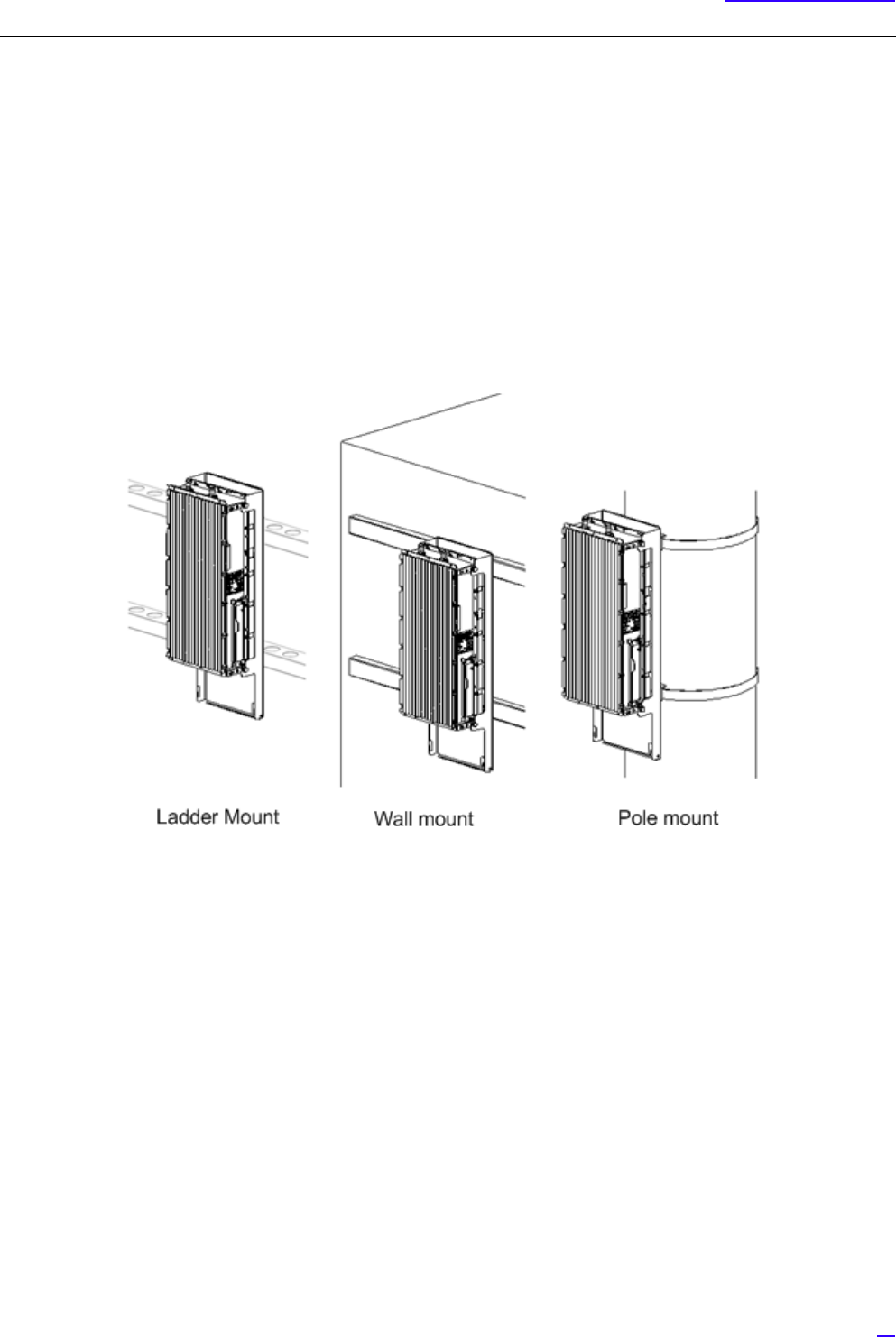
5.2.1 Installation Examples of Ladder/ Wall/ Pole/ Cross arm/ Suspension Mount
The following shows the images of ladder/ wall/ pole/ cross arm/ suspension mount of All-in-one Type eNB.
1Ladder mount/ Wall mount/ Pole mount
Figure 13 Installation Images Part 1
30
Equipment Installation
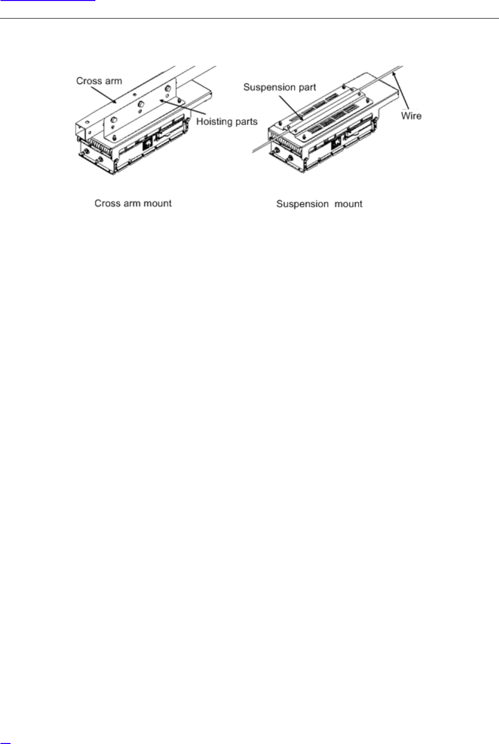
2Cross Arm Mount/ Suspension Mount
Figure 14 Installation Images Part 2
GWhen setting up the equipment horizontally, set it so that the mounting hardware is on the top face.
31
Equipment Installation
5.3 Ladder/ Wall/ Pole/ Cross Arm/ Suspension Installation
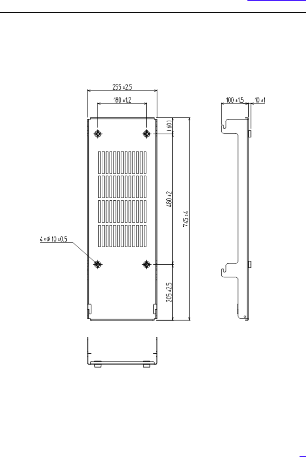
5.3.1 Dedicated Mounting Hardware for Installation
All-in-one Type eNB (ladder/ wall/ pole/ cross arm/ suspension mount) is installed using the dedicated mounting hardware
which is the standard installation method. For details on the dedicated mounting hardware, refer to the following figure.
Figure 15 Dedicated Mounting Hardware
32
Equipment Installation
5.3.2 Installation Method
The following shows the method to install All-in-one Type eNB (ladder/ wall/ pole/ cross arm/ suspension mount).
The following shows the image to mount the dedicated mounting hardware on the installation surface.
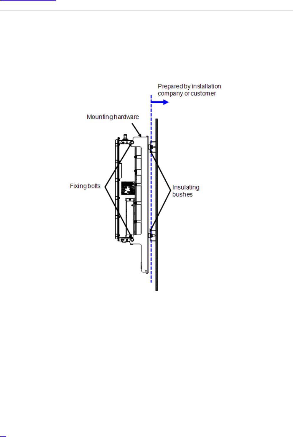
1Wall/ Ladder Mount
Figure 16 Wall/ Ladder Mount Installation Image
33
Equipment Installation
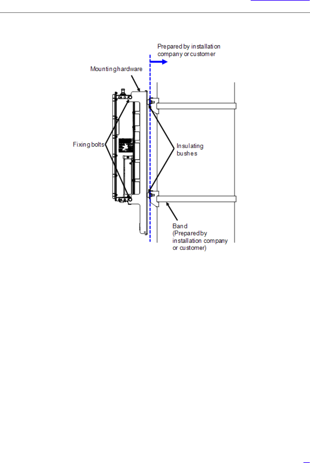
2Pole Mount
Figure 17 Pole Mount Installation Image
GThe bands and any ledge to put on the mounting hardware must be prepared by the installation company or
the customer.
34
Equipment Installation
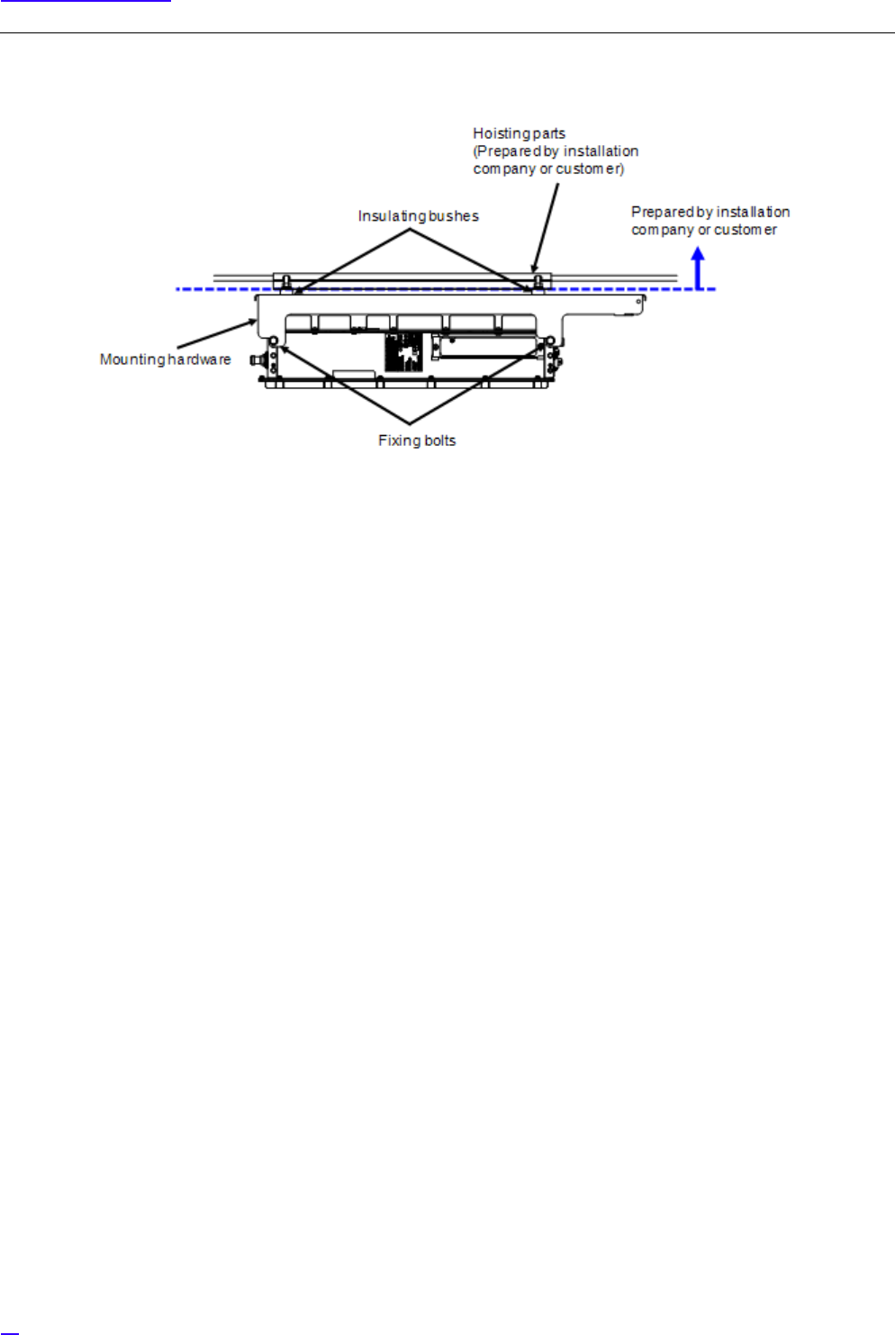
3Cross Arm/ Suspension Mount
Figure 18 Cross Arm/ Suspension Mount Installation Image
GCross Arms, suspension parts and cross arm fixing bolts on the power source column, etc., suspension part
mounting bolts, wires between poles must be prepared by the installation company or the customer.
35
Equipment Installation
5.3.3 Installation Procedure
The following shows the procedure to install All-in-one Type eNB (ladder/ wall/ pole/ cross arm/ suspension mount).
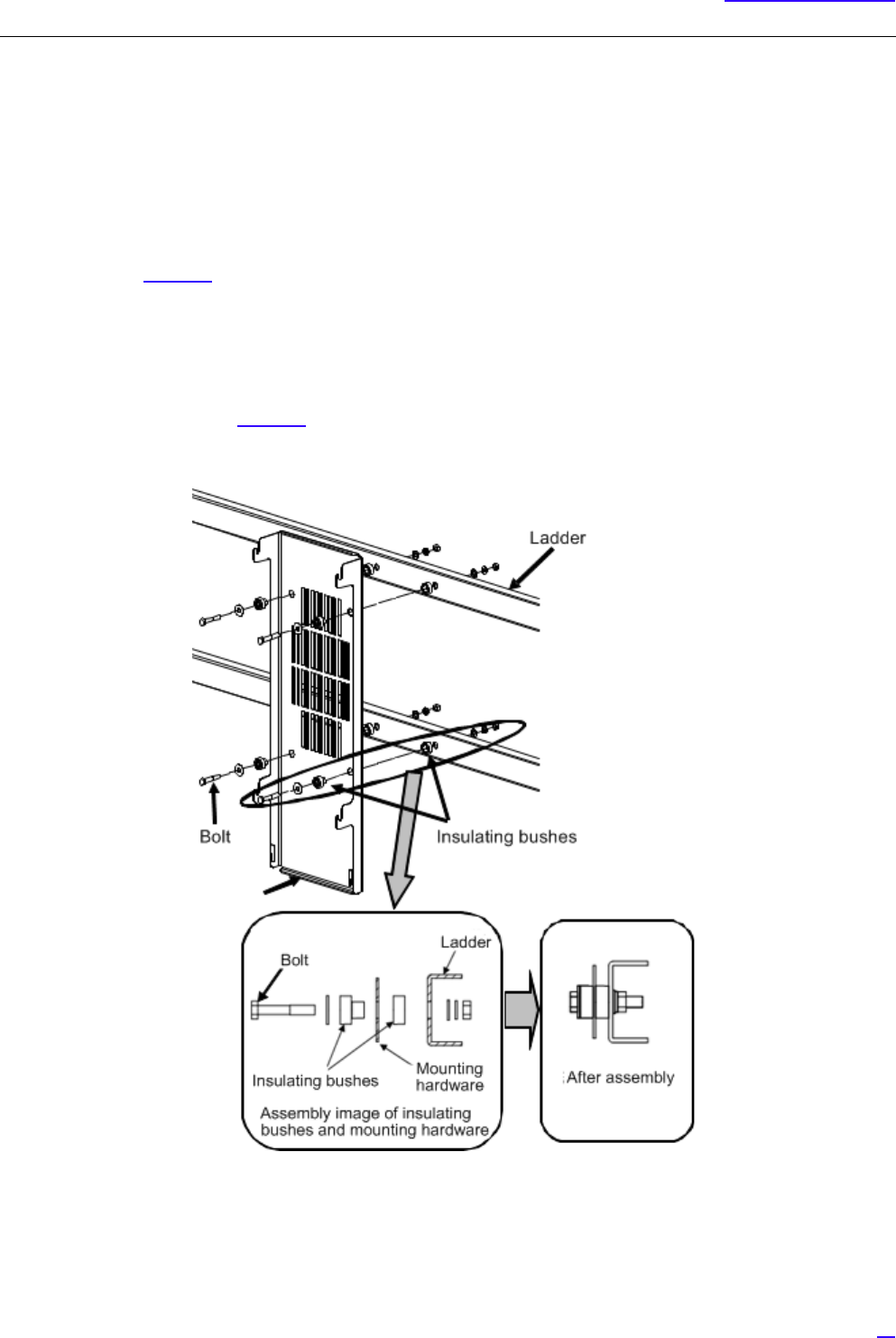
Installing the dedicated mounting hardware (ladder/ wall/ pole/ cross arm/ suspension)
GThis equipment requires electrical insulation with the installed surface, so when fixing by M8 bolts, insulating bushes
are used.
1Refer to Figure 19, and fix using M8 bolt with the bushes in the correct order.
If there is no male screw, fix with M8 nut, etc.
2Finally, tighten the bolts again, and mark the bolts. (M8: torque 17 ±1 N• m)
GIf there is no hole to install the equipment on the installed surface (ladder/ wall/ pole/ electrical pole/
suspension parts), perform drilling referring to the dedicated mounting hardware installation hole
dimensions (Figure 15).
Be careful not to deform the mounting hardware when fixing the equipment.
Figure 19 Dedicated Mounting Hardware Installation
36
Equipment Installation
Installing the Equipment to Dedicated Mounting Hardware
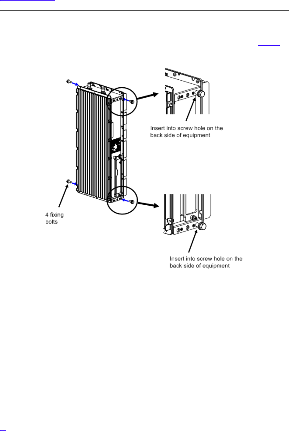
1Insert the 4 fixing bolts into the screw holes on the top, bottom, left and right side of equipment (the back side hole
out of the 3 screw holes in a row) for about the half of their length and temporarily fix them. Refer to Figure 20 for
installation of fixing bolts
Figure 20 Fixing Bolts Installation
37
Equipment Installation
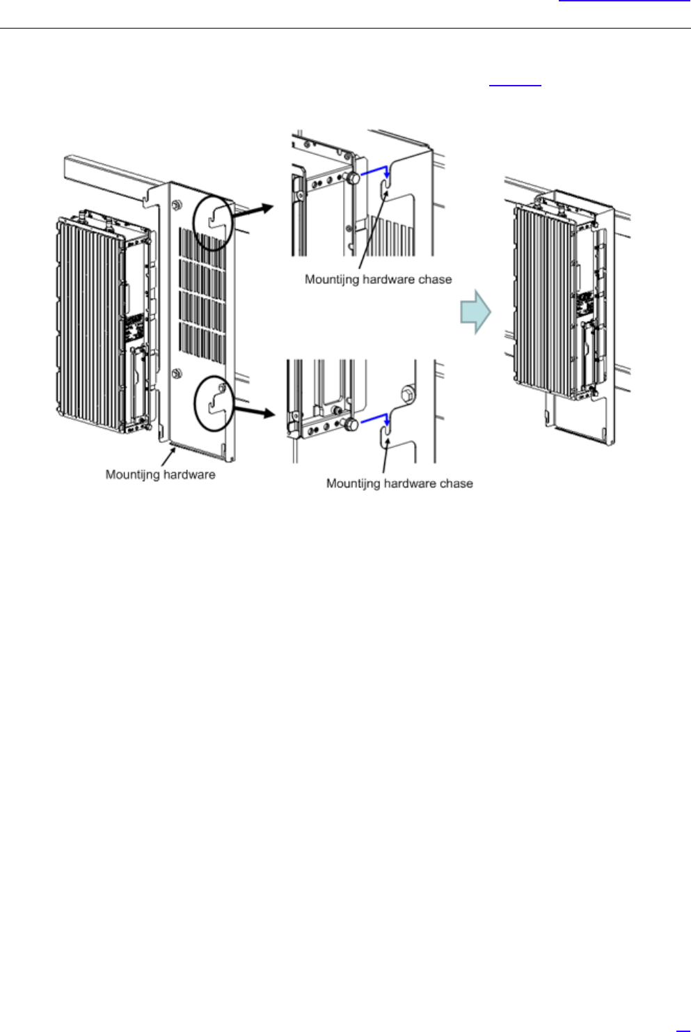
2Hang the equipment by the four M8 bolts (attached to equipment) temporarily fixed in step (1) onto the chases
on top/ bottom/ left and right of the dedicated mounting hardware. Refer to Figure 20 for installation onto the
mounting hardware.
Figure 21 Installing the Equipment onto the Mounting Hardware
38
Equipment Installation
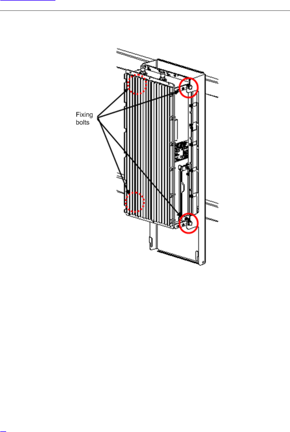
3Tighten the four M8 bolts temporarily fixed in step (1). Lastly, tighten the bolts further and mark the bolts, and
the installation is complete (torque value M8: 17 ±1 N• m).
Figure 22 Tightening the Fixing Bolts
39
Equipment Installation
5.3.4 C-COVER (Connector Cover) Installation Procedure
GC-COVER is an optional part.
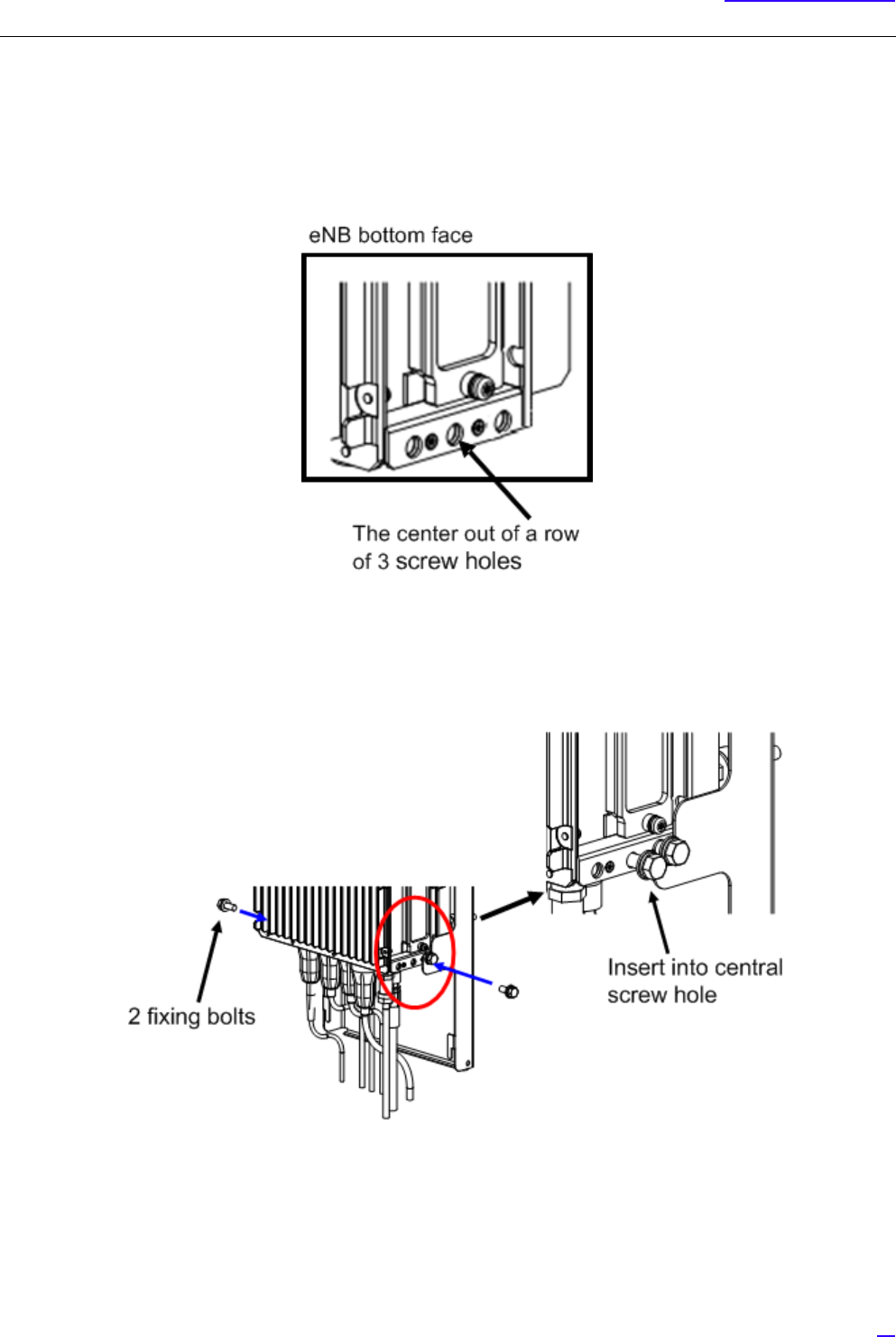
1Check the screw holes (the center of the 3 screw holes) on the left and right sides of eNB equipment.
Figure 23 Right Side Fixing Bolt Installation Location (Reference)
2Insert the two fixing bolts into the screw holes on the left and right sides of the equipment bottom part (the center
of the 3 screw holes) for half of its length and fix temporarily.
Figure 24 Installing Fixing Bolts
40
Equipment Installation
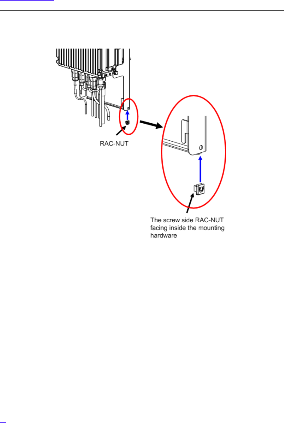
3Set a RAC-NUT into the round hole on the mounting hardware, with the screw side facing inward.
Figure 25 Installing RAC-NUT
41
Equipment Installation
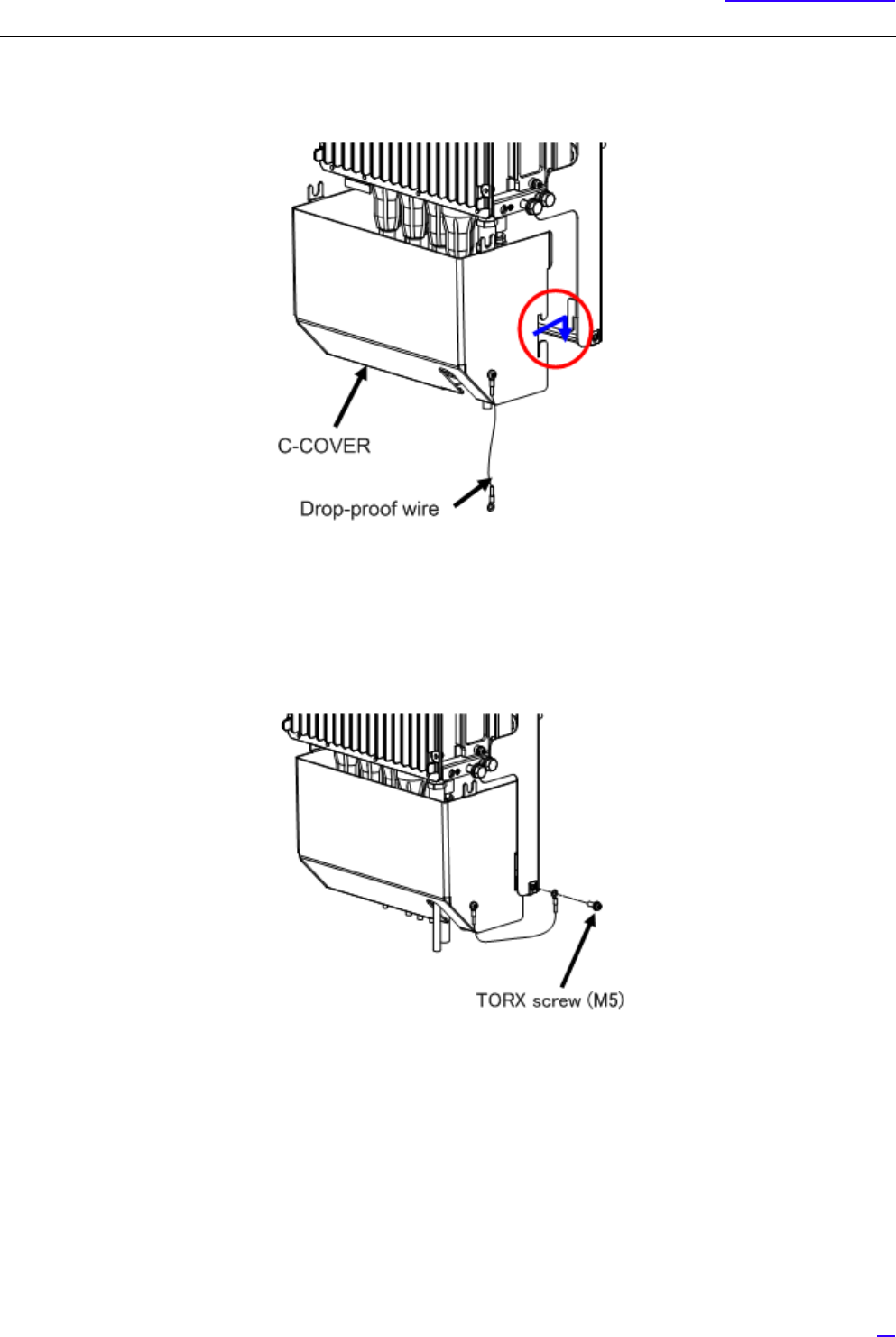
4Set the C-COVER chase to the protruding parts on the left and right of dedicated mounting hardware, and pull
the C-COVER a little downwards to hang the C-COVER on the mounting hardware.
Figure 26 Temporarily Installing the C-COVER
5Fix the drop-proof wire of the C-COVER using a TORX screw (M5) onto the dedicated mounting hardware
(torque value M5: 4 ±0.5 N• m).
Figure 27 Installing the Drop-Proof Wire
GPulling the drop-proof wire of the C-COVER strongly may cut it off. If the wire is cut, there is a risk of the
C-COVER dropping when trying to remove it.
42
Equipment Installation
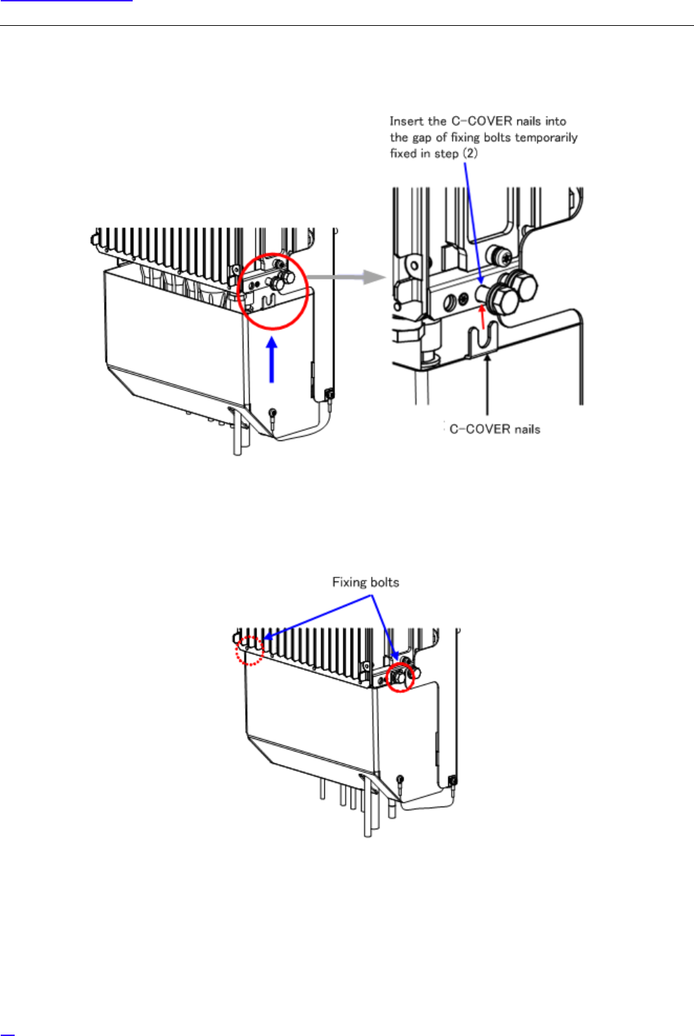
6Lift the C-COVER upwards (in direction indicated by the blue arrow), and insert (red arrow) the C-COVER nails
into the gaps of two fixing bolts of the left and right side, which were temporarily fixed in step (2).
Figure 28 Temporarily Installing the C-COVER
7Tighten the fixing bolts which were temporarily fixed in step (2). Finally, tighten the bolts again and mark the
bolts, and the installation procedure is complete (torque value M8: 17 ± 1 N•m).
Figure 29 Tightening the Fixing Bolts
43
Equipment Installation
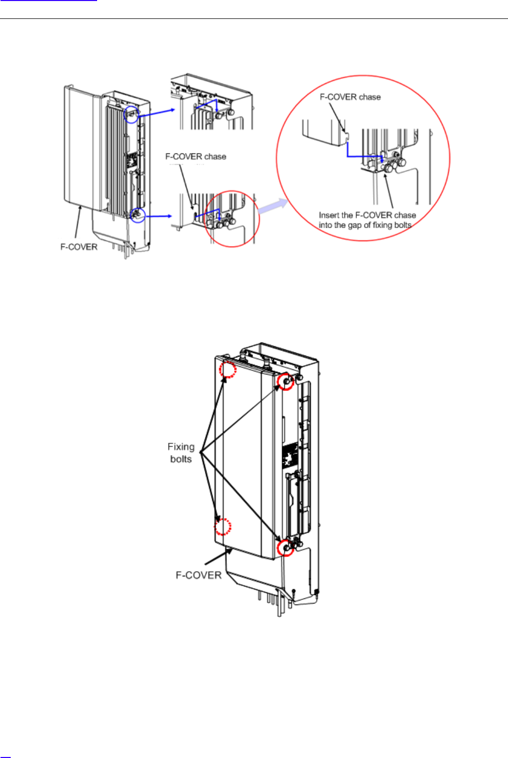
5.3.5 F-COVER (Front Cover) Installation Procedure
GF-COVER is an optional part.
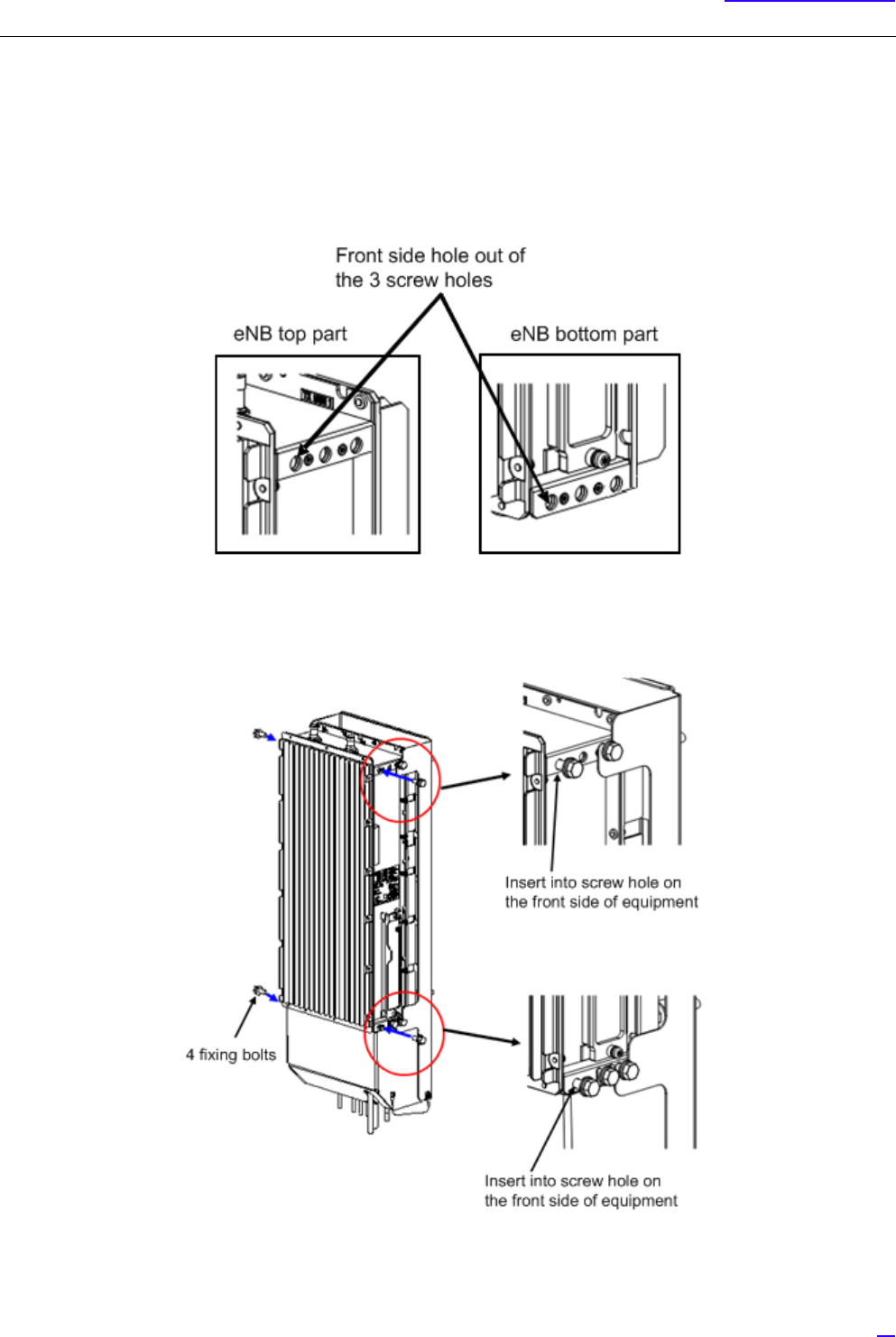
1Check the screw holes (front side hole out of the three screw holes) on the top, bottom, left and right to set the
fixing bolts.
Figure 30 Installation Location of Fixing Bolts on the Right Side Top and Bottom (Reference)
2Insert the four fixing bolts (attached parts) into the screw holes (front side hole out of the three screw holes) on
the top, bottom, left and right of equipment for half of their length and fix temporarily.
Figure 31 Installing Fixing Bolts
44
Equipment Installation
3Insert the F-COVER chase into the gap of fixing bolts temporarily fixed in step (2).
Figure 32 Installing the F-COVER
4Tighten the four fixing bolts on top, bottom, left and right which were temporarily fixed in step (2). Finally, tighten
the bolts again and mark the bolts, and the installation procedure is complete (torque value M8: 17 ± 1 N•m).
Figure 33 Tightening the Fixing Bolts

45
Equipment Installation
5.4 List of Attachments and Tools
The following lists the attachments and tools required for equipment installation.
Table 7 Attachment List
Item Name Quantity Note
For FG (M6 + pan head screw) 1 Mount on equipment
Connector caps 1 set Mount on equipment
Dedicated mounting hardware 1 set Including installation parts
F-COVER 1 set Optional, including installation parts
C-COVER 1 set Optional, including installation parts
Table 8 Tool List
Item Name Used for Note
M6 + Standard driver FG
TORX T25 size screw driver C-COVER drop-proof wire fixing screw
and maintenance window
With tamper-resistant pin
Hexagonal spanner (For M8) Dedicated mounting hardware, C-COVER
and F-COVER

46
Cable Work
6 Cable Work
6.1 List of Used Cables and Connectors
Table 9 shows the cables and connectors used for this equipment.
Table 9 Used Cables and Connectors
External Interface/
Name
Connectors on Equipment Connectors on Cable
Connector
type
1st line: Vender name
2nd line: Vender model
name
Connector
type
1st line: Vender name
2nd line: Vender model
name
Power source input
interface -48V DC
Square bipolar TE
FOAC FullAXS
BULKHEAD HOUSING +
square bipolar
FullAXS TE
FullAXS POWER
FLOATING or FullAXS
POWER FIXED
GPS interface / GPS N type
waterproof (J)
DDK
N-SR-J-1.5D
N type
waterproof
General-purpose
connector. No vender/
model name specified.
External alarm
interface / EXT ALM
RJ-45 TE
FOAC FullAXS
BULKHEAD HOUSING +
RJ45
RJ-45 TE
FullAXS SIGNAL
FLOATING
Optical BH interface /
BH(O)
LC 2-core
(MMF core
radius 50 μm)
TE
FOAC FullAXS
BULKHEAD HOUSING +
LC 2-core
LC 2-core TE
FOMM50 LEAD4.8mm
FullAXS LC/DPX-
LC/DPX
LC 2-core
(MMF core
radius 62.5
μm)
TE
FOAC FullAXS
BULKHEAD HOUSING +
LC 2-core
LC 2-core TE
FOMM62.5 LEAD4.8mm
FullAXS LC/DPX-
LC/DPX (Model name not
fixed: in discussion with
TE)
LC 2-core
(SMF)
TE
FOAC FullAXS
BULKHEAD HOUSING +
LC 2-core
LC 2-core TE
FOSM LEAD4.8mm
FullAXS LC/DPX-
LC/DPX
Metal BH interface /
BH(E)
RJ-45 TE
FOAC FullAXS
BULKHEAD HOUSING +
RJ45
RJ-45 TE
FullAXS SIGNAL
FLOATING
Antenna tilt control
input interface / RET
Round
waterproof (J)
IEC60130-9
Amphenol
AISG-RECE-CONNE-
SOCKET-TYPE01
Round
waterproof (P)
IEC60130-9
AISG general-purpose

47
Cable Work
RF antenna interface /
ANT0, ANT1
N type
waterproof (J)
N(F)4H BULKHEEAD
18.0-7.0
N type
waterproof (P)
General-purpose
connector. No vender/
model name specified.
Table 9 Used Cables and Connectors
External Interface/
Name
Connectors on Equipment Connectors on Cable
Connector
type
1st line: Vender name
2nd line: Vender model
name
Connector
type
1st line: Vender name
2nd line: Vender model
name
49
Cable Work
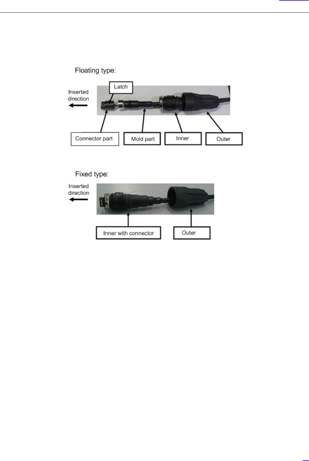
6.2.1 Power Cable Connection Composition
The following shows the connection composition of the power cable. There are two types of power cable: the Floating type
and the Fixed type.
Figure 35 Power Connection Cable Composition
50
Cable Work
6.2.2 Power Cable Connection Procedure
The following shows the procedure to connect the power cable.
G
1Check that the corresponding breaker is OFF when mating the power connector.
2Move the Inner and Outer straight to the insertion direction. Inserting them at an angle or twisting them may
damage the connector.
3Perform the connection while holding the cables close to the equipment, so that the connectors do not drop out
by the cable weight, etc.
4The Outer, Inner and the connectors are made out of plastic. Stepping on them or banging them may damage
them, so handle them with care.
5Even if the Outer is fixed, twisting the cable may place load to the internal connector and damage it. When
laying cables, be careful not to twist them.
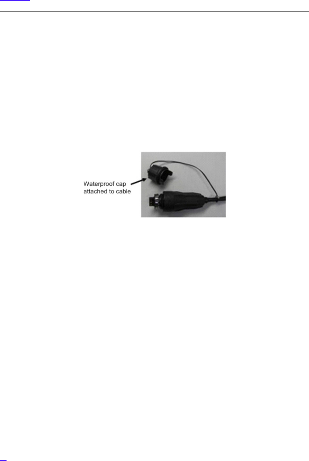
6After mating, discard the waterproof cap attached to the cable. The wind, etc. may break the cord, and the cap
may drop.
7When disconnecting the power cable, turn the power off from the power source.
8When laying cables, always keep the bend radius to 66 mm or more.
51
Cable Work
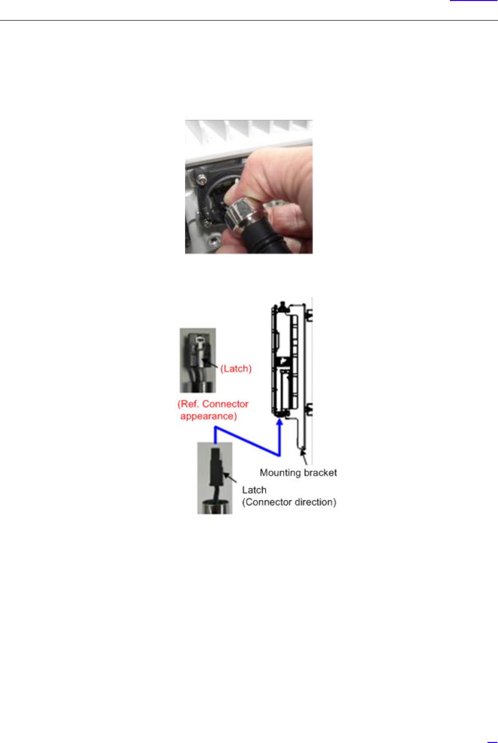
6.2.2.1 Floating Type Cable Connection Procedure
The following shows the procedure to connect the Floating type cable.
1Insert the connector part of the power cable to the equipment side connector.
(1) Connect the connector latch of the power cable towards the mounting hardware side of eNB equipment.
52
Cable Work
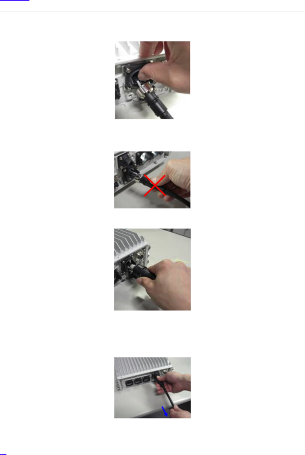
(2) Push in the connector of the power cable in until the latch mates.
GPushing in by force holding the mold part may damage the connector part. Make sure to hold the
connector part when connecting.
2Insert the power cable Inner straight into the connector on the equipment.
GWhen inserting the power cable Inner, there would be friction between the inner cable and the Inner, so
hold the cable with your hand while inserting.
After inserting the power cable Inner, pull the cable while still holding the cable with your hand, to closely
fit the mold part and the Inner.

53
Cable Work
3Rotate the power cable Outer clockwise to fix it in place.
54
Cable Work
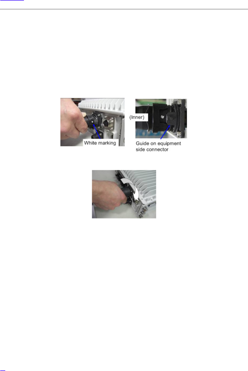
6.2.2.2 Fixed Type Cable Connection Procedure
The following shows the procedure to connect the Fixed type cable.
GInserting the power cable by force at a wrong connector position or with the connector facing upside down may
damage the connector and the printed circuit board inside the equipment. Do not insert the cable by force, and check
the direction of the power cable connector again.
1Positioning with the white marking, insert the power cable into the equipment connector until the Inner is beside
the guide on the equipment side connector.
2Pushing the power cable Outer, rotate it clockwise to fix it.

55
Cable Work
6.3 Backhaul Cable Connection
6.3.1 Metal Type Backhaul Cable Connection (BH(E))
Figure 36 shows the location of the connector to connect the backhaul (Electrical) cable.
Figure 36 eNB Bottom Face Cable Connection Position (Backhaul interface (Electrical))
The following shows the composition of the backhaul connection cable (Electrical).
Figure 37 Backhaul Connection Cable (Electrical) Composition
56
Cable Work
6.3.1.1 Backhaul Cable Connection Procedure (Electrical)
The following shows the procedure to connect the backhaul cable (Electrical).
G
1Move the Inner and Outer straight to the insertion direction. Inserting them at an angle or twisting them may
damage the connector.
2Perform the connection while holding the cables close to the equipment, so that the connectors do not drop out
by the cable weight, etc.
3The Outer, Inner and the connectors are made out of plastic. Stepping on them or banging them may damage
them, so handle them with care.
4Even if the Outer is fixed, twisting the cable may place load to the internal connector and damage it. When
laying cables, be careful not to twist them.
5After mating, discard the waterproof cap attached to the cable. The wind, etc. may break the cord, and the cap
may drop.
6When laying cables, always keep the bend radius to 22 mm or more.
1Insert the RJ45 connector part to the equipment connector, until the latch mates.
57
Cable Work
2Insert the Inner straight into the equipment connector.
GWhen inserting the Inner, there would be friction between the inner cable and the Inner, so hold the cable
with your hand while inserting.
3Rotate the Outer clockwise to fix it in place.
58
Cable Work
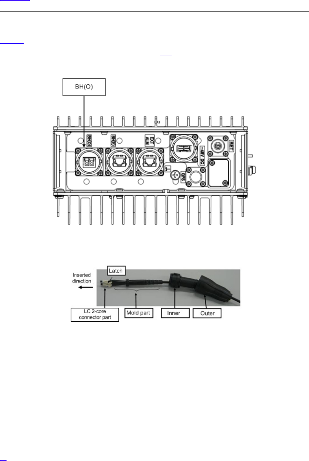
6.3.2 Optical Type Backhaul Cable Connection (BH(O))
Figure 38 shows the position of the connector to connect the backhaul (Optical) cable.
GFor notes on handling the optical cable, refer to section 6.3.3.
Figure 38 eNB Bottom Face Cable Connection Position (Backhaul Interface (Optical))
The following shows the backhaul connection cable (Optical) composition.
Figure 39 Backhaul Connection Cable (Optical) Composition
59
Cable Work
6.3.2.1 Backhaul Cable Connection Procedure (Optical)
The following shows the procedure to connect the backhaul cable (Optical).
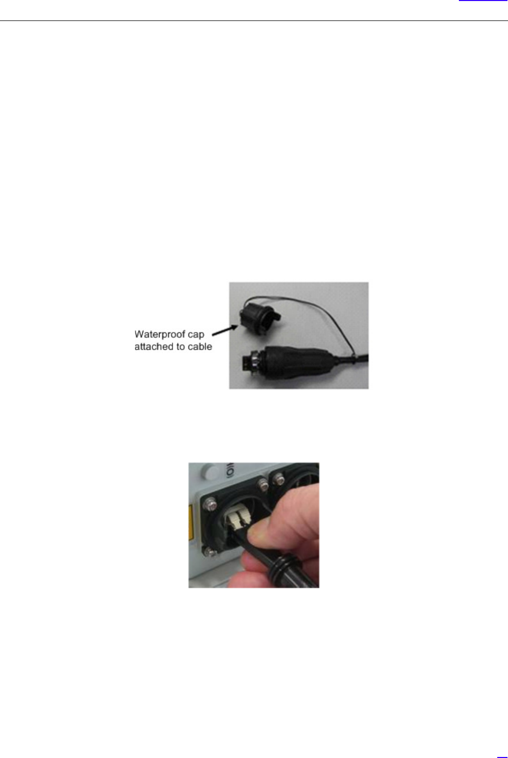
G
1When connecting cable to BH(O), remove the waterproof cap on BH(O) and put it on BH(E).
2Move the Inner and Outer straight to the insertion direction. Inserting them at an angle or twisting them may
damage the connector.
3Perform the connection while holding the cables close to the equipment, so that the connectors do not drop out
by the cable weight, etc.
4The Outer, Inner and the connectors are made out of plastic. Stepping on them or banging them may damage
them, so handle them with care.
5Even if the Outer is fixed, twisting the cable may place load to the internal connector and damage it. When
laying cables, be careful not to twist them.
6After mating, discard the waterproof cap attached to the cable. The wind, etc. may break the cord, and the cap
may drop.
7When laying cables, always keep the bend radius to 30 mm or more.
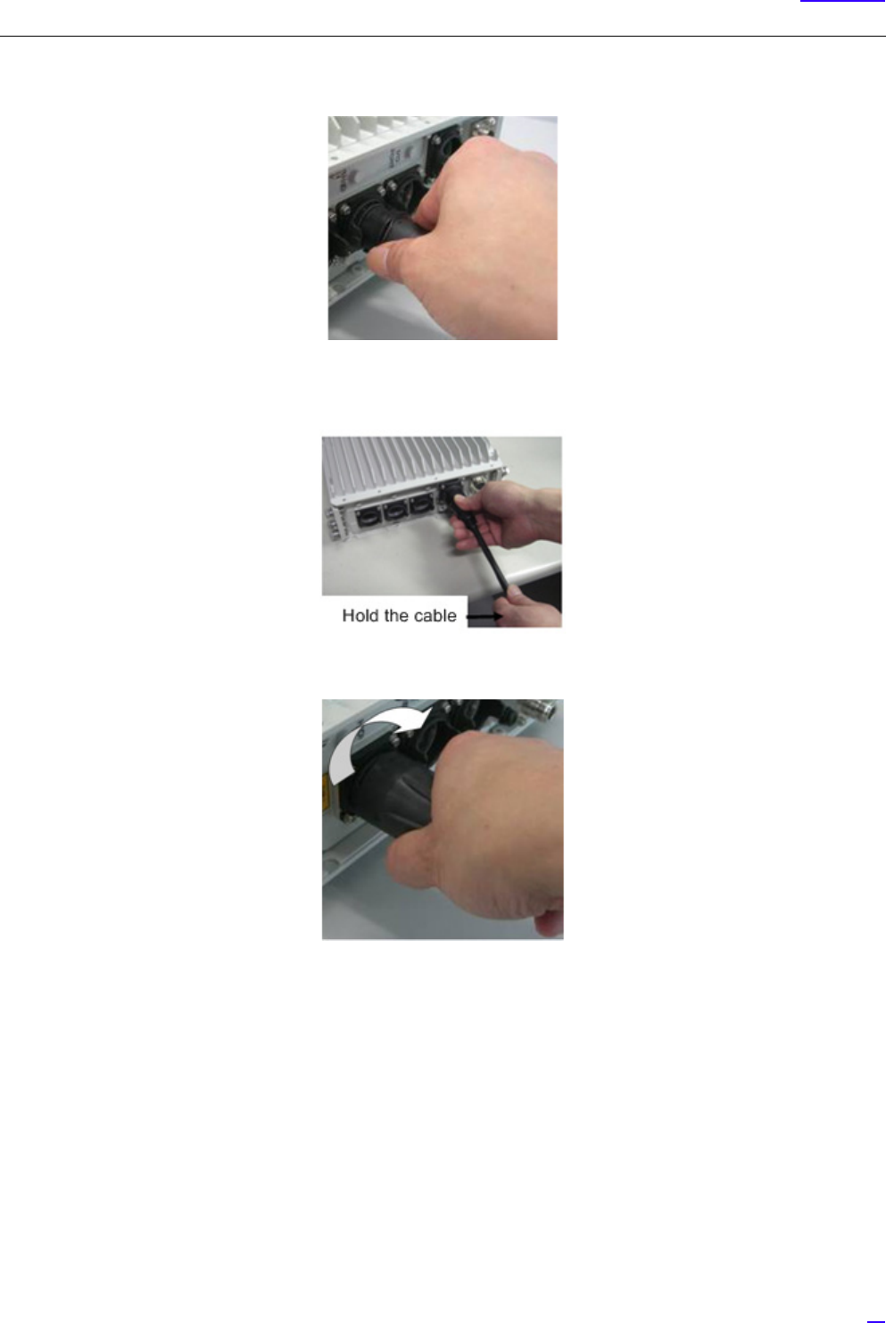
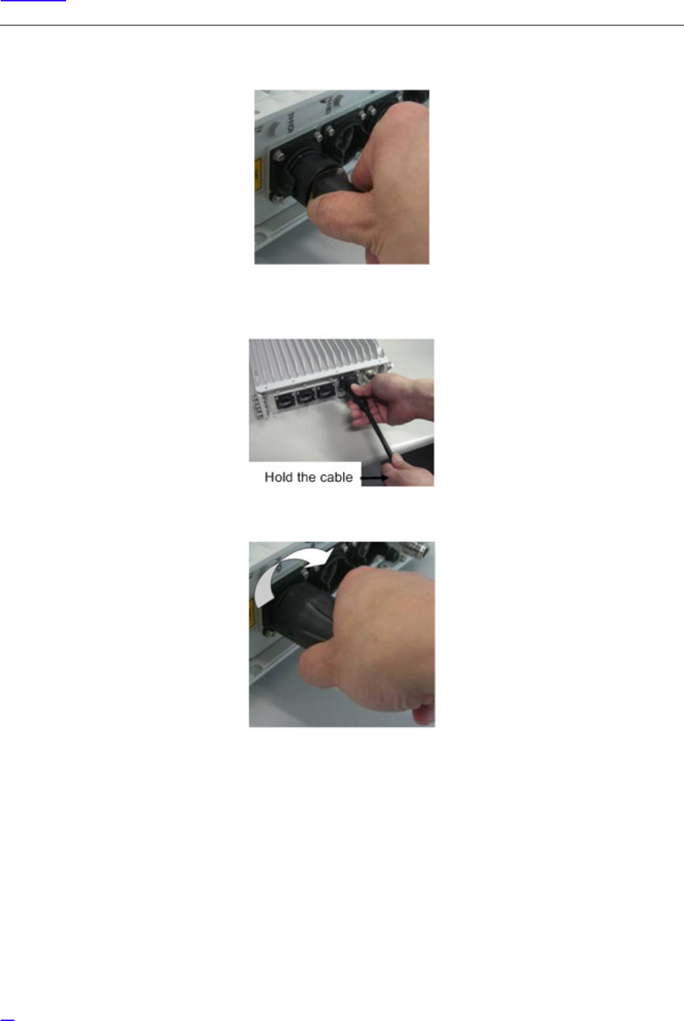
1Insert the LC 2-core connector part into the equipment SFP, until the latch mates.
60
Cable Work
2Insert the Inner straight into the equipment SFP.
GWhen inserting the Inner, there would be friction between the inner cable and the Inner, so hold the cable
with your hand while inserting.
3Rotate the Outer clockwise to fix it in place.
61
Cable Work
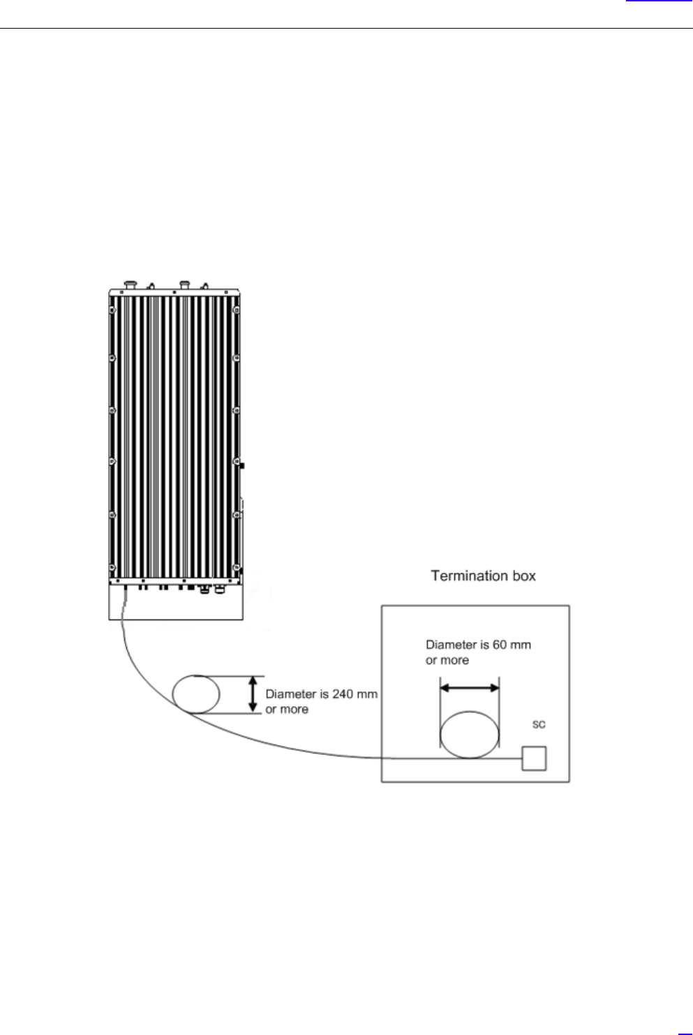
6.3.3 Notes on Handling Optical Cables
The following shows the notes on handling the optical cables.
G
1When applying surplus treatment to the optical cable connecting the BH(O) connector of this equipment and
the termination box, keep the outdoor armored cable bend radius to 120 mm (240 mm in diameter) or more.
2When applying surplus treatment inside the termination box, keep the able bend radius to 30 mm (60 mm in
diameter) or more for the parts without outdoor armored cable.
3Applying too much force on the optical cable may damage it. Connect the optical cable so that it is not twisted.
4When fixing the optical cable, tie the optical cable so that it is not twisted.
Figure 40 Surplus Treatment of Optical Cable
•Cleaning Equipment SFP and Optical Cable LC Connector
Use the cleaning utensil (stick type) (for φ 1.25) to wash the ferrule (pin-shaped) end-face and side-face of the contact
terminal on the SFP and optical cable LC connector mating part. (Alcohol cannot be used together)
GDo not reuse the cleaning utensil already used once. Invisible dust is attached on the used utensil so reusing it
may damage or contaminate the optical cable.
62
Cable Work
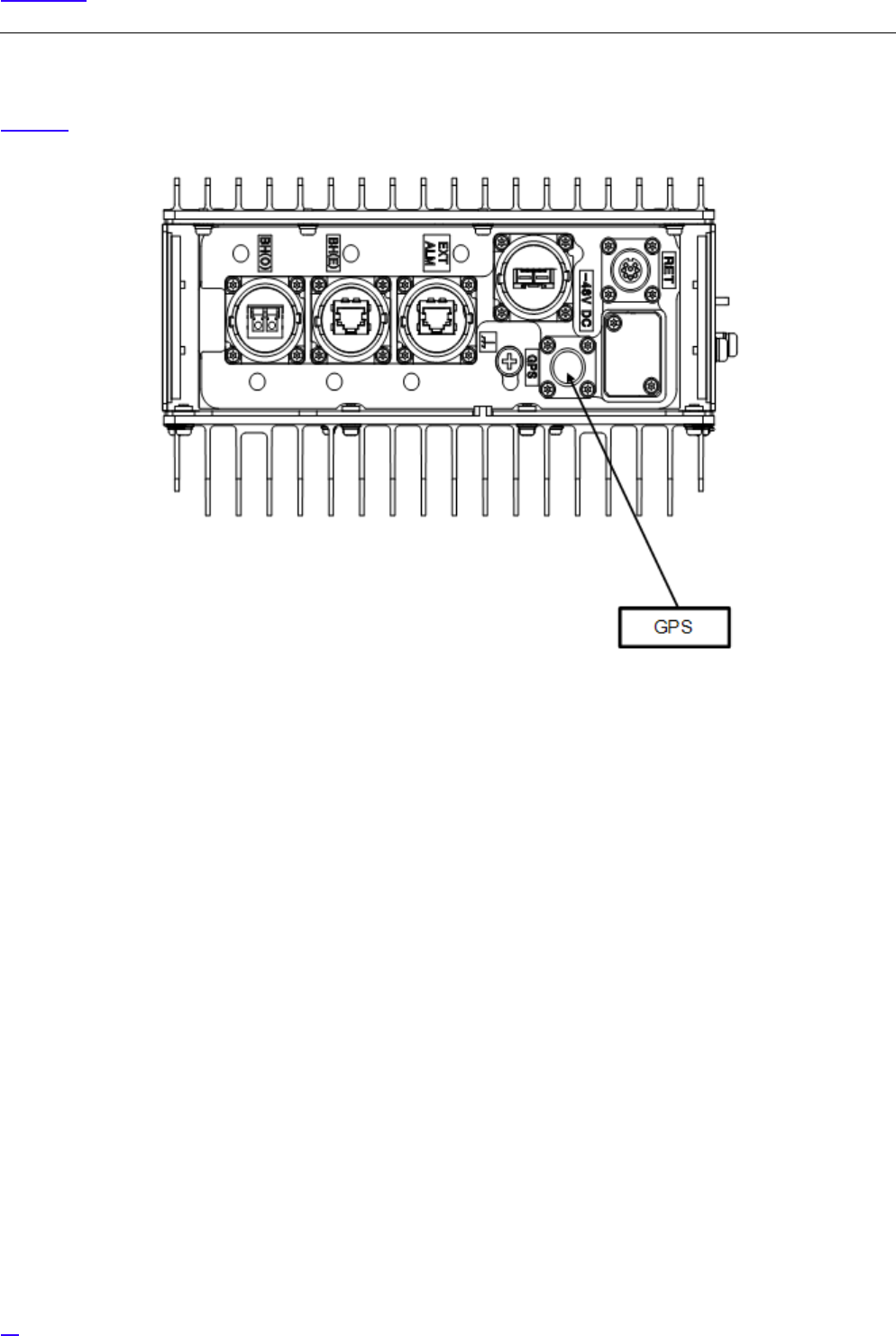
6.4 GPS Cable Connection (GPS)
Figure 41 shows the position of the connector to connect the GPS cable.
Figure 41 Bottom Face Cable Connection Position (GPS connector)
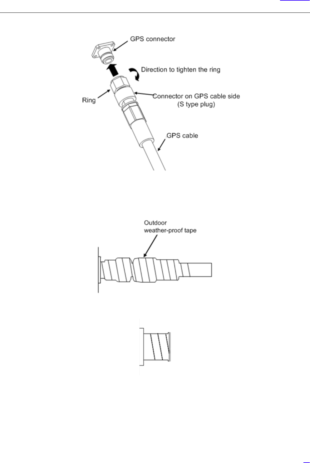
6.4.1 GPS Cable Connection Procedure
The following shows the procedure to connect the GPS cable.
1Insert the GPS connector into the GPS connector on the eNB equipment.
2After holding the ring on the GPS cable against the GPS connector on the eNB equipment, tighten until the male
screw ridges of the GPS connector on the eNB equipment are invisible.
Recommended tightening torque is 0.7 N•m to 1.1 N•m.
63
Cable Work
Figure 42 GPS Cable Connection
3To prevent the mating part loosening, it is recommended to protect the connector on the eNB equipment up to
the cable (so that the cable side connector is completely covered) with outdoor weather-proof tape.
Figure 43 GPS Cable Connector Protection Example
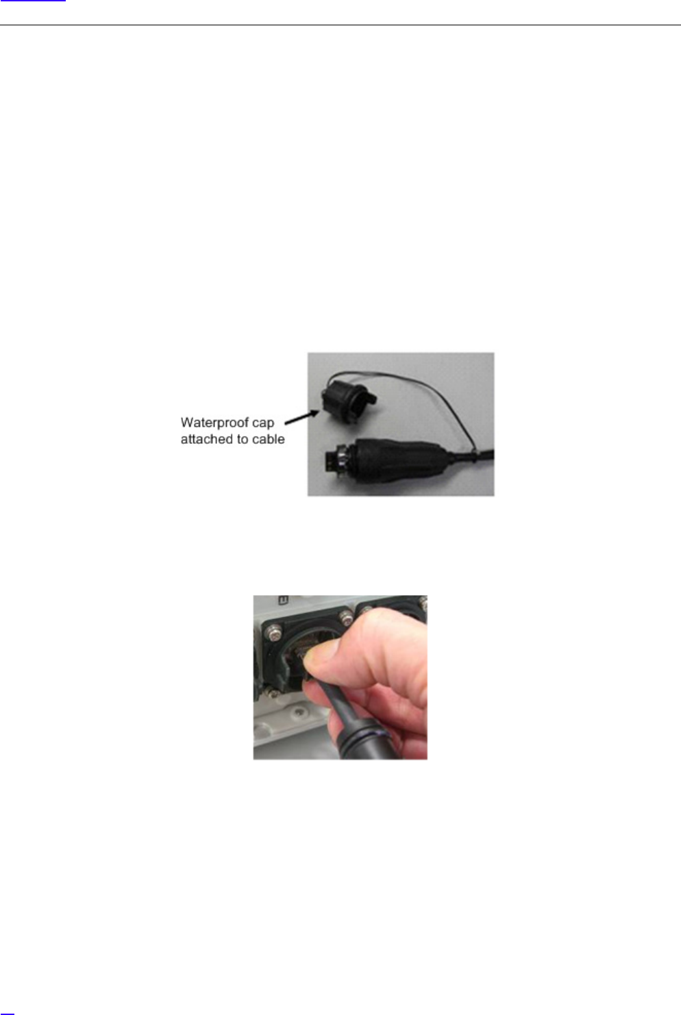
Figure 44 GPS Cable (with Waterproof Cap)
64
Cable Work
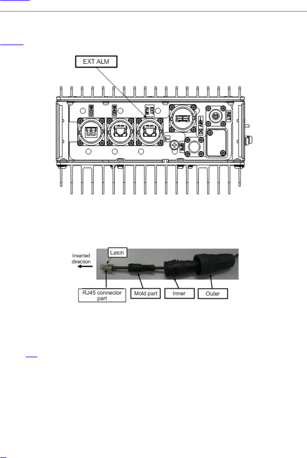
6.5 External Alarm Interface Cable Connection (EXT ALM)
Figure 45 shows the position of the connector to connect the external alarm interface cable.
Figure 45 Bottom Face Cable Connection Position (External Alarm Interface (EXT ALM))
The following shows the external alarm interface connection cable composition.
Figure 46 External Alarm Interface Connection Cable Composition
6.5.1 External Alarm Interface Cable Connection Procedure (EXT ALM)
The connection procedure of the external alarm interface cable is the same as that of the metal type backhaul cable, so refer
to section 6.3.1 .
65
Cable Work
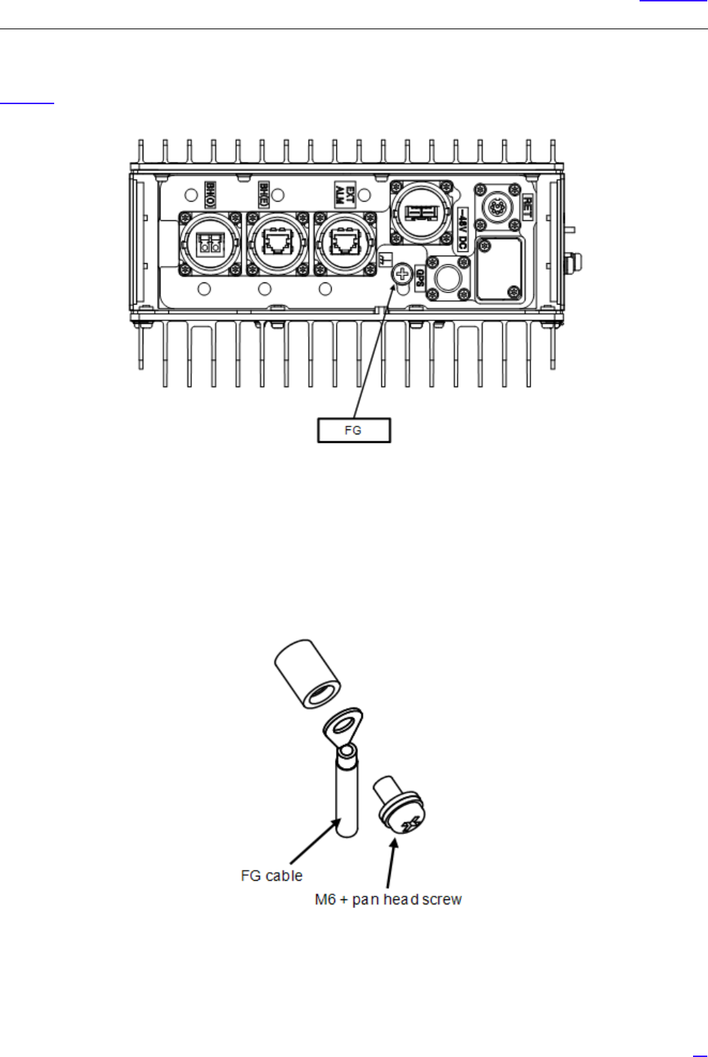
6.6 FG Cable Connection (FG)
Figure 47 shows the position of the Frame Ground (FG) connector screw to connect the FG cable.
Figure 47 Bottom Face Cable Connection Position (FG)
6.6.1 FG Cable Connection Procedure
The following shows the procedure to connect the FG line.
1Use the M6 + pan head screw installed on the FG terminal to connect the FG cable to the equipment.
Figure 48 FG Terminal Connection Part
66
Cable Work
G
1The recommended tightening torque is 4 N•m.
2When connecting the FG cable, connect it so that it would take the shortest way to the ground point
in the office.
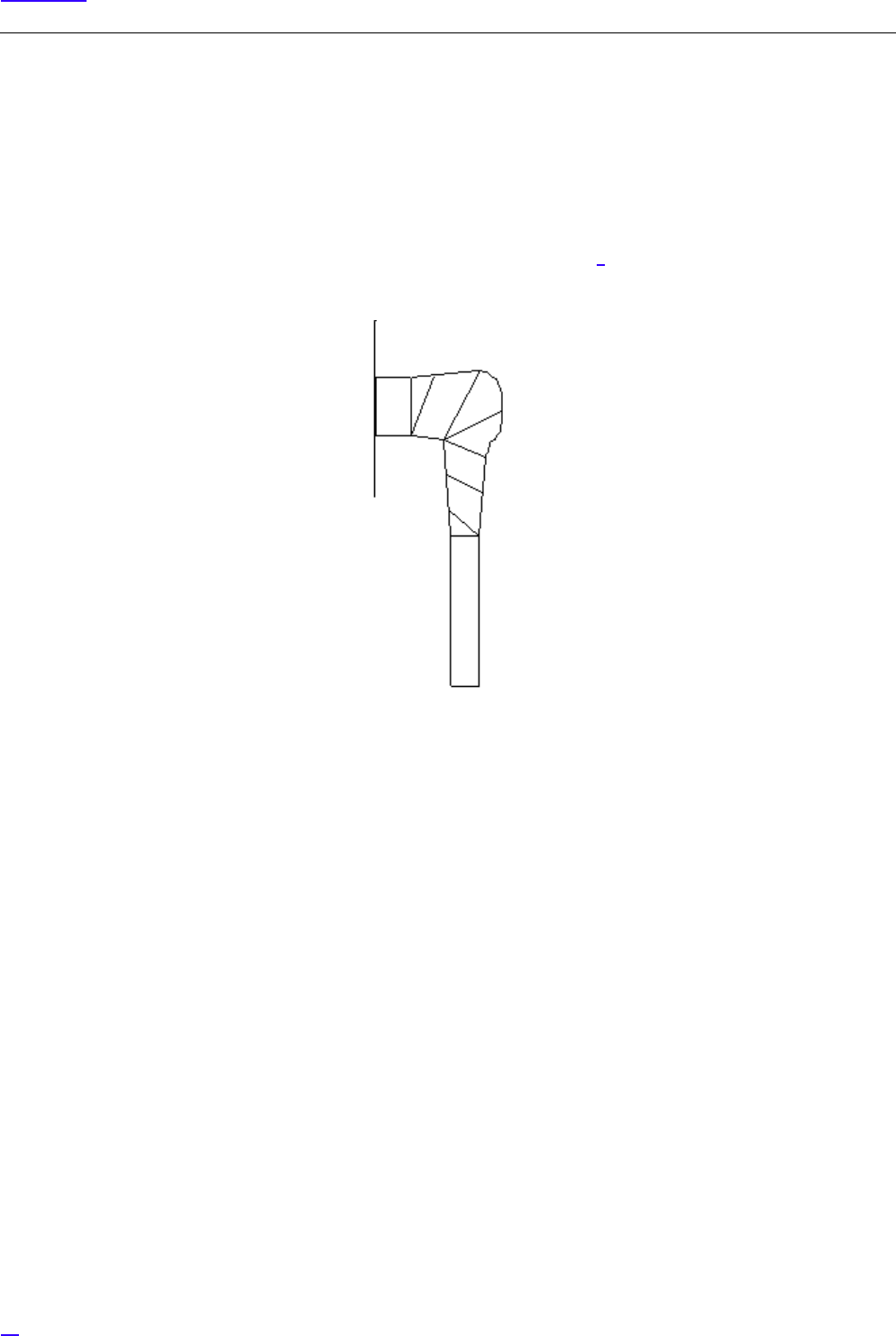
2To prevent loosening, it is recommended to protect the connector on the eNB equipment + pan-head screw to the
FG line (so that the FG line side crimping terminal is completely covered) with outdoor weather-proof tape.
GApply protection after checking the voltage referring to section 7. If protection is applied before checking
the voltage, some voltage check procedure cannot be performed.
Figure 49 Crimping Terminal Mounting Screw Protection Example
67
Cable Work
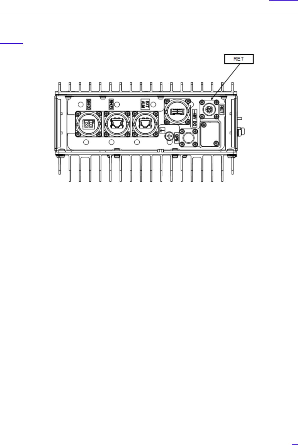
6.7 Antenna Tilt Control Cable Connection (RET)
Figure 50 shows the position of the connector to connect the antenna tilt control cable.
Figure 50 Bottom Face Cable Connection Position (RET)
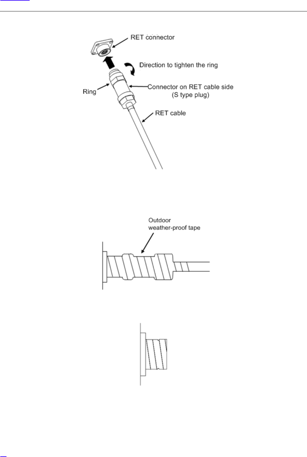
6.7.1 Antenna Tilt Control (RET) Cable Connection Procedure
The following show the procedure to connect the antenna tilt control (RET) cable.
1Insert the antenna tilt control cable connector into the antenna tilt control connector on the eNB equipment.
2Holding the ring of the antenna tilt control cable against the antenna tilt connector on the eNB equipment, use
your hand to tighten the ring on the cable clockwise.
Recommended tightening torque is 1.0 N•m to 1.2 N•m.
68
Cable Work
Figure 51 Antenna Tilt Control Connector Connection
3To prevent the mating part loosening, it is recommended to protect the connector on the eNB equipment up to
the cable (so that the cable side connector is completely covered) with outdoor weather-proof tape.
Figure 52 Connector Protection Example (RET)
Figure 53 Waterproof Cap Protection Example

69
Cable Work
6.8 Antenna Cable Connection (ANT0/ANT1)
Figure 54 shows the positions of the connectors to connect the antenna cable.
Figure 54 Top Face Cable Connection Position (Antenna Cable)
6.8.1 Antenna Cable Connection Procedure (ANT0/ANT1)
The following shows the procedure to connect the antenna cable.
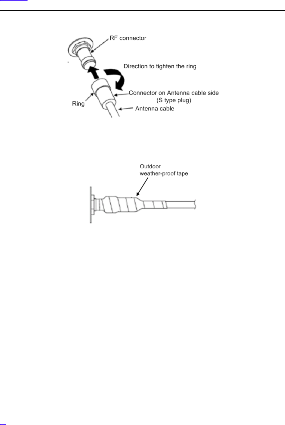
1Insert the antenna cable connector into the RF connector on the eNB equipment.
2Holding the ring on the antenna cable against the RF connector on the equipment, tighten the ring of the antenna
cable until the male screw ridges of the RF connector on the equipment are invisible.
Recommended tightening torque is 0.7 N•m to 1.1 N•m.
70
Cable Work
Figure 55 Antenna Cable Connection
3To prevent the mating part loosening, it is recommended to protect the connector on the eNB equipment up to
the cable (so that the cable side connector is completely covered) with outdoor weather-proof tape.
Figure 56 Connector Protection Example (ANT)
71
Cable Work
6.9 Connector Details
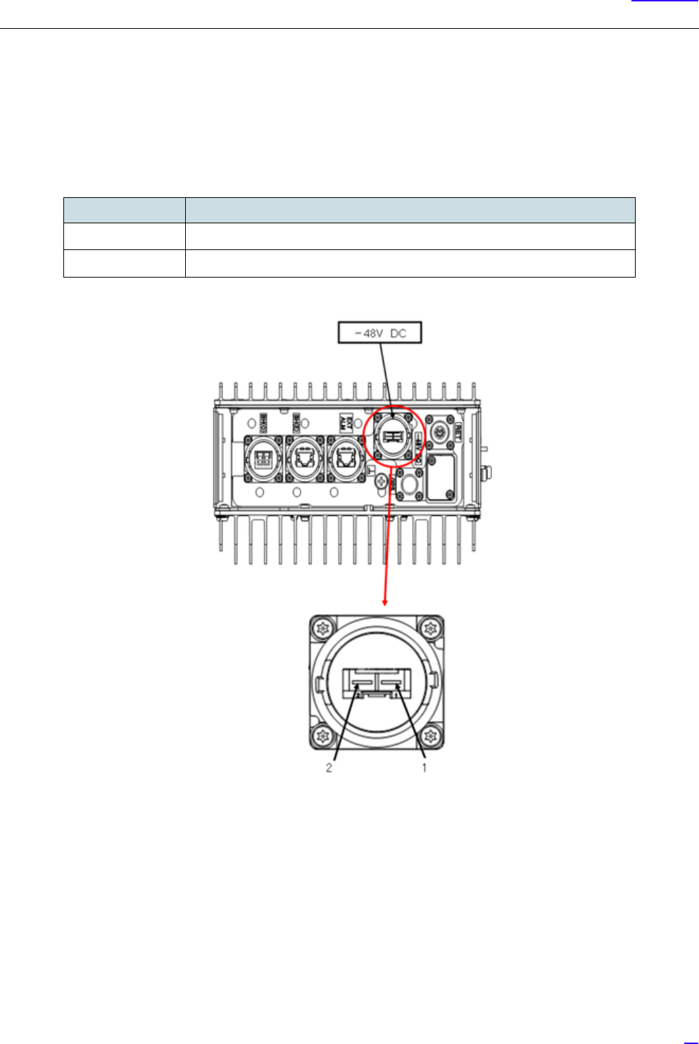
6.9.1 Power Connector Pin Allocation
The following shows the pin allocations on the power connector installed on the eNB equipment.
Figure 57 Power Connector Pin Allocations
Table 10 Terminal Number and Signal Names
Pin No. Signal name
1-48V DC
20V
72
Cable Work
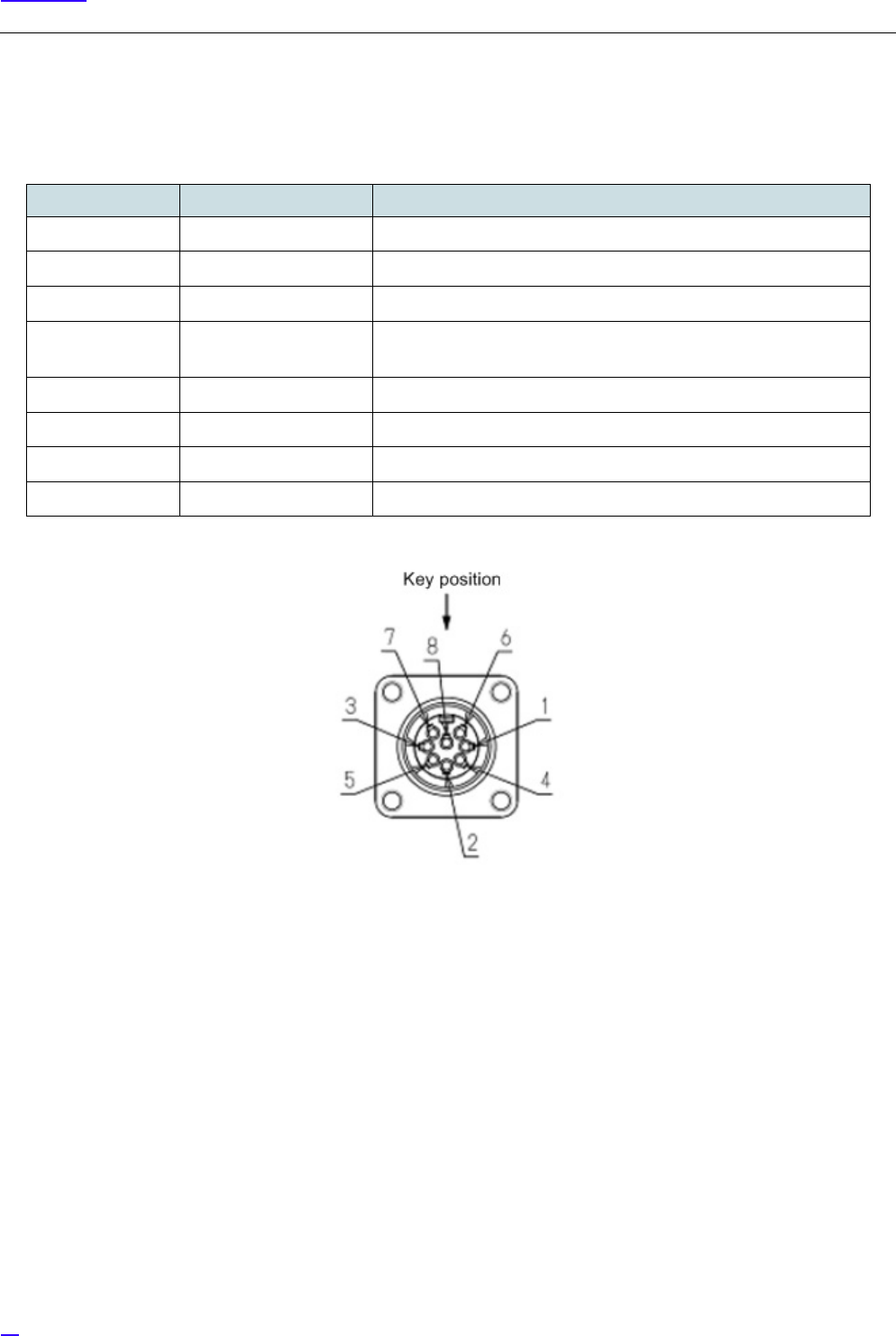
6.9.2 Antenna Tilt Control Connector (IEC60130-9)
The following shows the pin allocations for the antenna tilt control connector on the eNB equipment.
Figure 58 Pin Allocations for Antenna Tilt Control Connector
Table 11 Terminal Number and Signal Names
Pin No. Signal name AISG Requirement
1+12V DC nominal Not supported
2-48V DC nominal Not supported
3RS485 B Would be supported
4RS485 GND For eNB, it is supported. Whether it is used or note depends on RET
support situation.
5 RS485 A Would be supported
610V -30V DC Would be supported
7DC return Would be supported
8N/C Reserved for future extension.
73
Cable Work
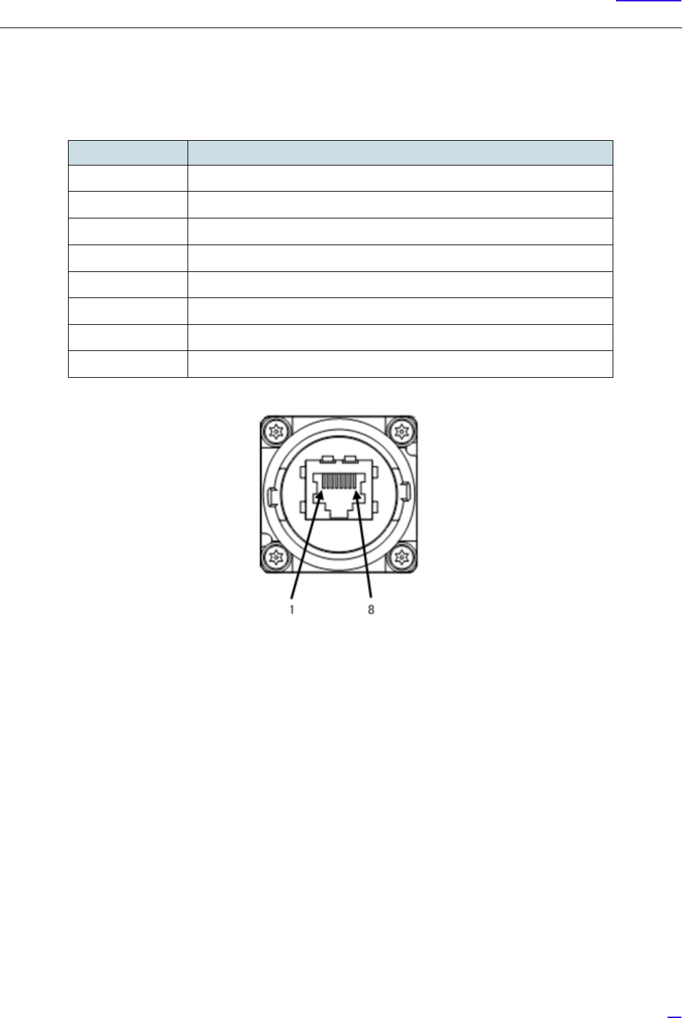
6.9.3 External Alarm Interface (EXT ALM)
The following shows the pin allocations of the external alarm interface (EXT ALM) on the eNB equipment.
Figure 59 Pin Allocation for External Alarm Interface (EXT ALM) Connector
Table 12 Pin Number and Signal Name
Pin No. Signal name
1Output 1 (Make)
2Output 1 (Break)
3Output 1 (Common)
4Input 1-G
5Input 1
6-
7Input 2-G
8Input 2
74
Voltage Check
7 Voltage Check
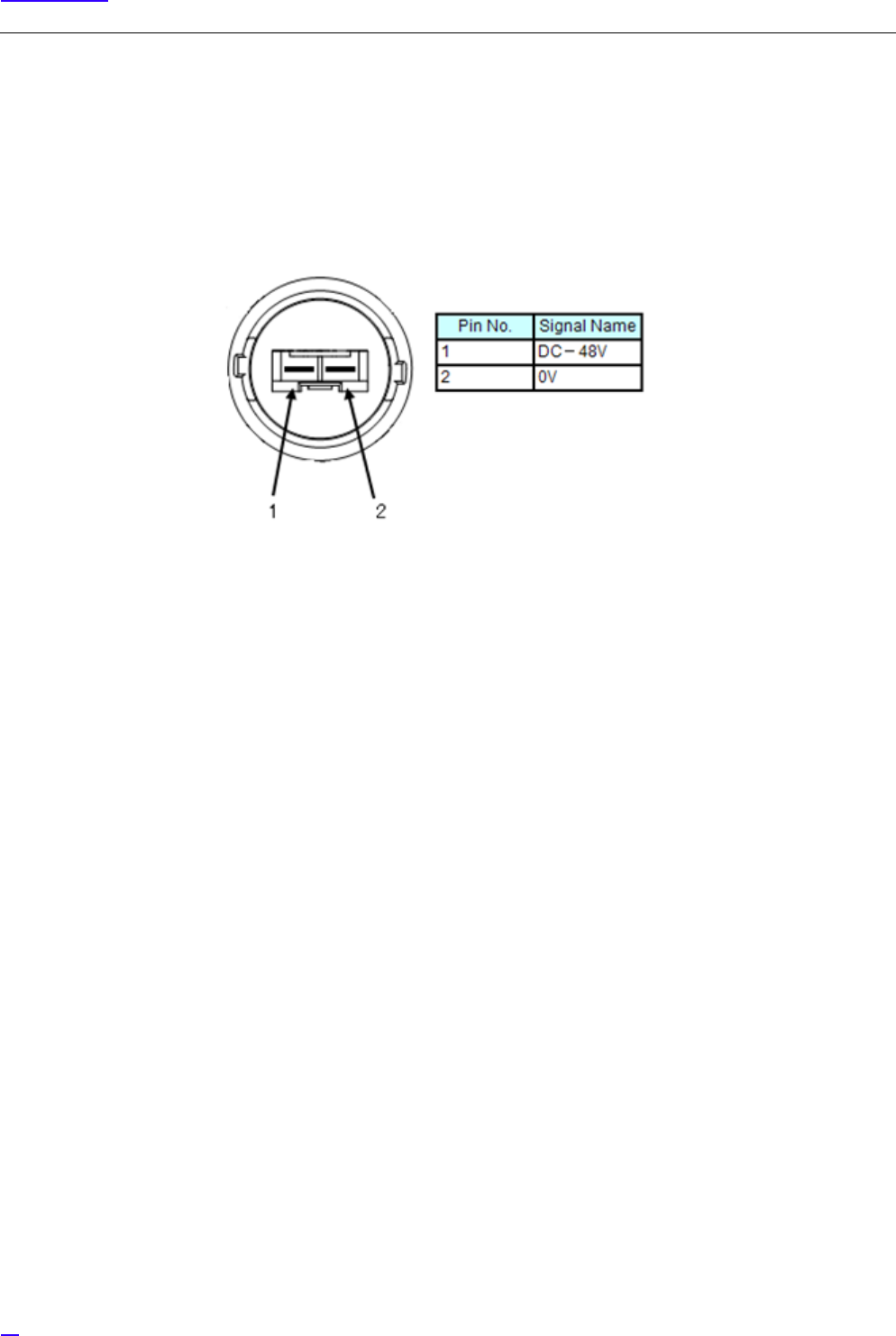
7.1 Cable Side Power Connector Pin Location Polarity
The following shows the pin location polarity image and details of the cable side power connected to the Power Distribution
Board (PDB) side breaker.
Figure 60 Cable Side Power Connector Pin Location Polarity
75
Voltage Check
7.2 Voltage Check Procedure
The following show the procedure to check the voltage.
1Prepare the tester in advance. Check that the tester operates normally before starting the test.
2Check the target location by sight and by reading out.
3Insulate and cure the necessary parts of the cable side power connector, DC power distribution board and DC
breaker to prevent short-circuit accidents.
4No voltage check of the breaker
Check that the target breaker on the power distribution board side is turned OFF by sight, and perform no voltage
check on the power distribution board side using the tester.
1Check that the red lead bar is connected to the + on the tester, and black lead bar to the –COM on the tester.
2Change the tester range to VDC range. For a tester with the Ampere range, check with two people or more
that the measurement is not performed in Ampere range and that the test bar insertion positions to the tester
are correct.
3Connect the red lead bar of the tester to the plus (+) pole of the target power distribution board breaker, and
the black lead bar to its minus (-) pole.
4Check that the value displayed on the tester is 0V (no voltage, logical value).
5Disconnect both the lead bars of the tester from the breaker terminals.
5Cable Side Power Connecter Voltage Check
Check that the target power distribution side breaker is turned OFF by sight, and perform no voltage check of the
cable side power connecter using the tester.
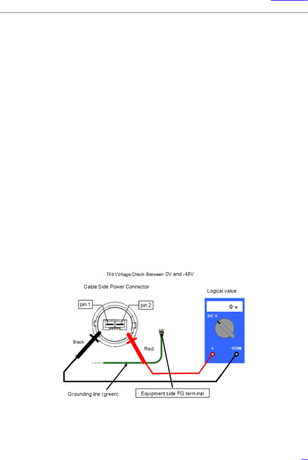
1Connect the red lead bar of the tester to the 0V terminal (pin 2) on the cable side power connector, and the
black lead bar to its -48V terminal (pin 1).
2Check that the value displayed on the tester is 0V (no voltage, logical value).
76
Voltage Check
6Keep each lead bar (red and black) of the tester connected as is, and instruct another worker to turn ON the target
breaker.
GAfter the worker checks the position of the target breaker by the drawing, the target device name displayed
on the power distribution and the destination plate attached to the power cable, the worker turns ON the
target breaker. Moreover, the supervisor would always be present and checks on the work.
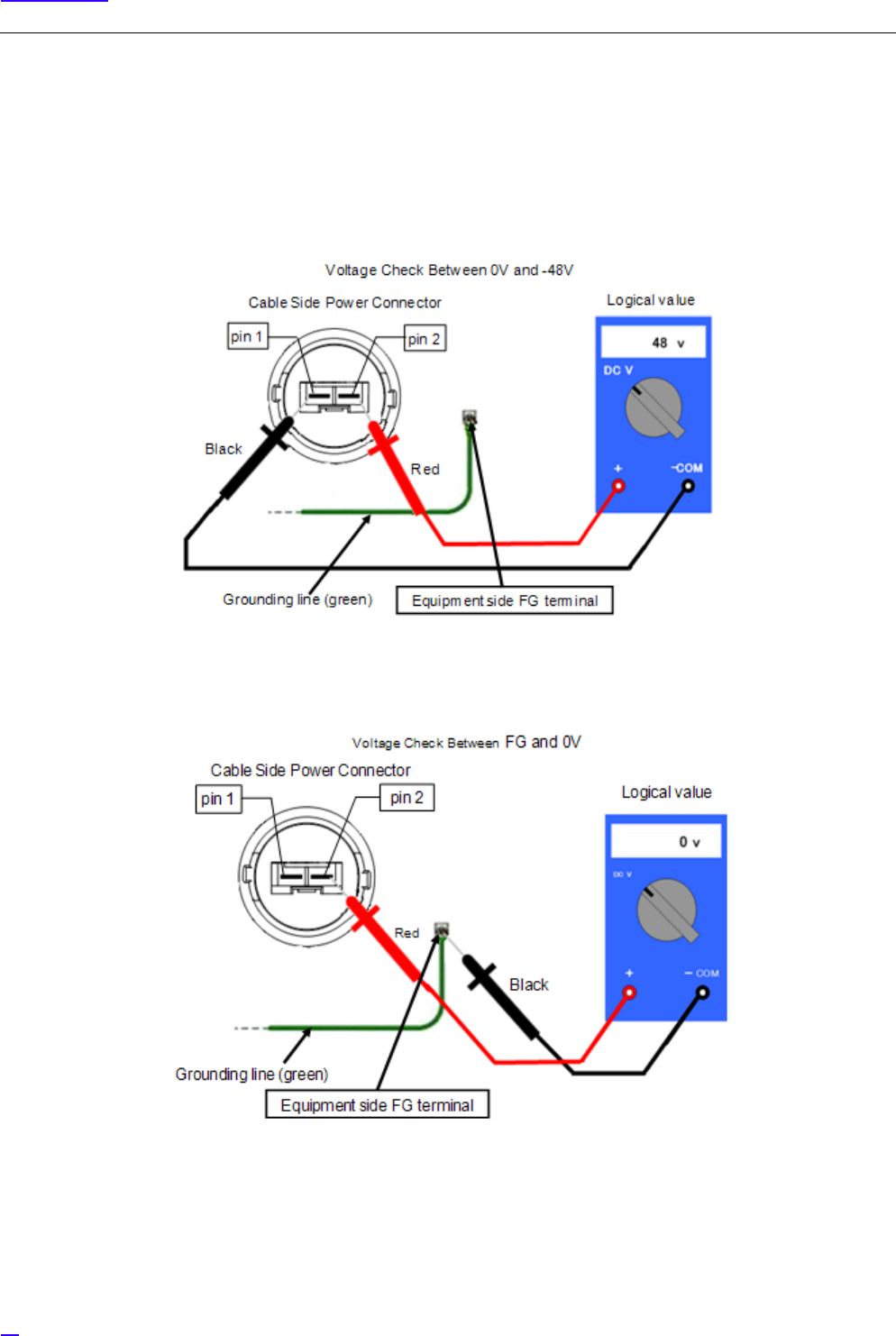
7Check that the breaker switch is turned ON, and 48V (logical value) is displayed on the tester.
8Keeping the red lead bar connected to the 0V terminal (pin 2) of the cable side power connector, slowly move the
black lead bar to the grounding terminal (E or FG) and connect to it. Upon connection, check that the voltage
changes from 48V to 0V (logical value).
77
Voltage Check
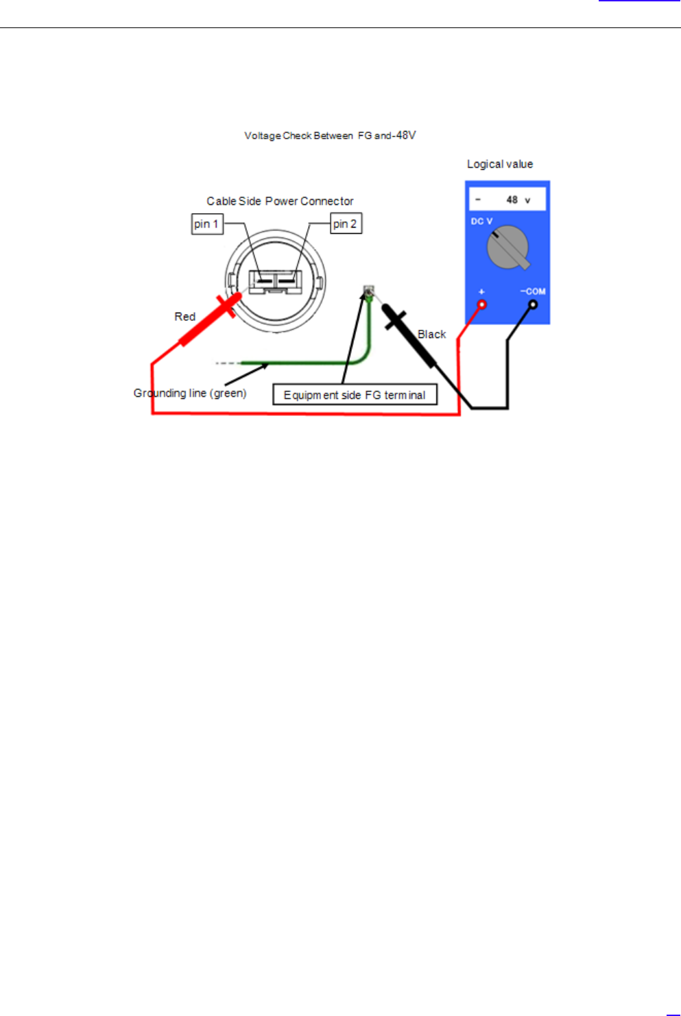
9Keep the black lead bar connected to the grounding terminal (E or FG), slowly move the red lead bar from the 0V
terminal (pin 2) of the cable side connector to the -48V terminal (pin 1), and connect to it. Upon connection, check
that the voltage changes from 0V to -48V.
10 Check that the polarities of the logical value and the actual measurement value are the same, the voltage value is
almost the same as the above logical value, in a range allowed by the device characteristics, or is an appropriate
voltage specified by the rectifier.
11 When the voltage check is complete, check the target breaker again and turn the breaker OFF (upon turning OFF,
check again that the cable side power connector is in 0V (no voltage)).
12 Remove the cure materials, and attach the power distribution board breaker terminal protection cover (fix by
screws and check the tightening).
13 Connect the cable side power connecter to the power connector on the equipment side.
14 Clean up the site.