NETWORK KOREA AEWC-2000 Web Camera User Manual CCD manual
NETWORK KOREA CO., LTD. Web Camera CCD manual
Users Manual

1
Acknowledgement
Thank you very much for purchasing the ATEYE of Network Korea.
• ATEYE Web Camera is developed and produced with only Korean
technologies.
• ATEYE Web Camera is marketed and sold after thorough quality verification.
• ATEYE Web Camera guarantees the rights and interests of consumers with
perfect customer service.
• ATEYE Web Camera will expand the ranges of your selection with various
products.
Customer Service Center
• Address: 1st Daeryug Techno Town, 327-24, Kasan-dong, Keumcheon-gu,
Seoul, 153-023, Korea.
• Tel: 02-857-5455
• Fax: 02-857-5480
• URL: WWW.NETKOREA4U.COM
Copyright
• The software and hardware mentioned in this user manual are the property of Network
Korea Co., Ltd. All software and hardware are protected by computer program protection
act, copyright act and international copyright conventions including other intellectual
property acts and conventions. No part of this manual may be reproduced or transmitted in
any form or by any means without permission in writing from Network Korea.
Contents
1. ATEYE Web camera Items & Specifications
1) Items
2) Specifications
2. ATEYE Web Camera Installation
1) Setting ATEYE Web Camera
1.1) Setting the camera ID
1.2) Setting baud rate
1.3) Setting termination
2) Composite cable ( BNC & RCA )
3) Connecting serial cable
3. ATEYE Web Camera Protocol
4. Troubleshooting
1. ATEYE Web Camera Items & Specifications
2
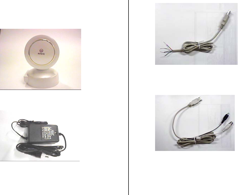
1) Items
(1) ATEYE Web Camera
(2) DC 12V 600mA Adaptor
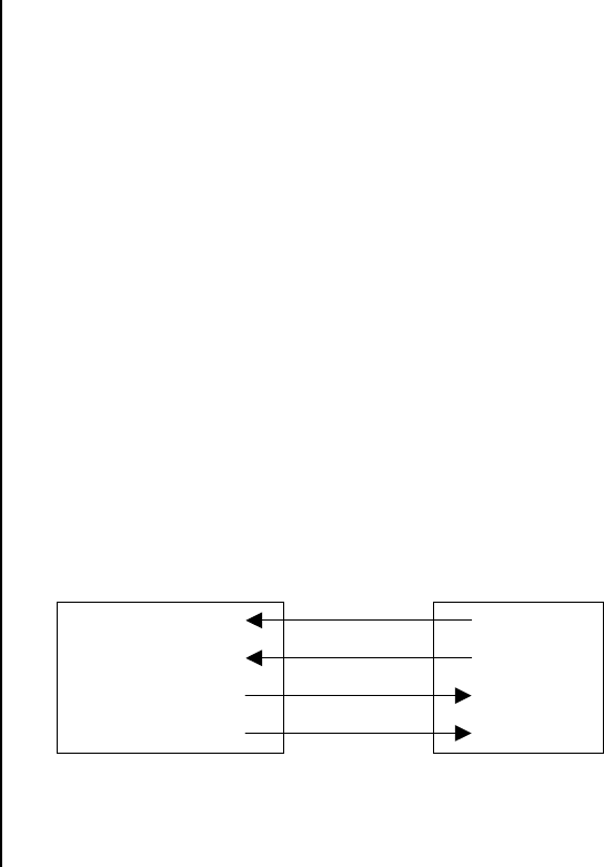
(3) Serial Cable (RS485 )
(4) Composite cable( BNC & RCA )
(5) User’s Manual
2) Specifications

3
ATEYE Web Camera
Video Format NTSC Standard : 525 Lines
30 Frames/sec
Scanning System 1/4 Interline
Effective Total Pixel No. 510(H) * 492(V)
Signal System 525 Lines Interface
Scanning Frequency Horizontal : 15.734KHz, Vertical : 59.94Hz
Synchronization Internal Synchronization
Resolution More than 360 Lines
Signal Output Analog Composite (1.0Vp-p, 75 ohm)
S/N ratio More than 48dB
Minimum Illumination 2Lux
Gamma 0.45
Motion range PAN : 320° TILT : -30° ~ +45°
Maximun Pan Speed 80°/sec
Maximun Tilt Speed 80°/sec
Control Interface RS485
Preset 64 Positions
Sensor Out One
Power DC 12V, 600mA
2. ATEYE Web Camera Installation
1) Setting ATEYE Web Camera
[Figure.1] the 8-bit DIP switch factory setting
1.1) Setting the camera ID
ATEYE Web Camera has an inherent camera ID. The total number of camera ID
is 64 from number 0 to number 63. How to set the camera ID is followed.
There is a 8-bit DIP switch in the bottom of ATEYE Web Camera
Among those switches in Figure.1, the pins of number 1-6 are used for
setting camera ID.
Number 1 switch is the lowest level bit(LSB) and number 6 is
the highest level bit(MSB).
If the switch is set on, the value is “1”, otherwise, it is “0”. ( binary number )
Example ) In case camera ID is number 5
4
Switch number 1 => On
Switch number 2 => Off
Switch number 3 => On
Switch number 4 => Off
Switch number 5 => Off
Switch number 6 => Off
That is
101000 => Camera ID is number 5
1.2) Setting the baud rate
ATEYE Web Camera is allowed to use two type of baud rate
;4800[bps], 9600[bps].
Number 7 switch of 8-bit DIP switch is used for that purpose.
If the switch is on, the baud rate is 9600bps, otherwise it is 4800bps.
1.3) Setting the termination
In case that you control more than two ATEYE Web Cameras with one
controller, you must set the termination for preventing the control signal being
lost.
You can use this by handling the last switch of 8-bit DIP switch at figure.1.
If you use only one ATEYE Web Camera with one controller, the switch must be
on,
Otherwise, you must set the switch of one ATEYE Web Camera on and that of
the others off.
the 8-bit DIP switch factory setting is followed.
Camera ID : 1
Baud rate : 9600 bps
Termination : On
2) Composite cable ( BNC & RCA )
A composite cable (BNC & RCA connector) is used in video out & Alarm out.
It is described the protocol of Alarm out in detail in the next pages.
3) Connection the serial cable
ATEYE Web Camera originally uses RS485 communications.
The color information of serial cable is followed.
camera controller (DVR etc.)
red Rx(+)
white Rx(-)
green Tx(+)
black Tx(-)
Tx(+)
Tx(-)
Rx(+)
Rx(-)
It is described the protocol in detail in the next pages
3. ATEYE Web Camera Protocol

5
Data Length 1 Byte (8 bit)
Start/Stop Bit 1 Bit
Parity Bit None
Baud rate 4800bps, 9600bps(default)
Protocol Format
start code Func_num Data3 Data2 Data1 Data0 Cam_ID Cam_ID
start code : 0x01
Func_num : Function byte
Data3 ~ Data0 : Data bytes
Cam_ID : Camera ID
Check Sum : Check Sum
Sum = FC_NUM + DATA3 + DATA2 + DATA1 + DATA0 + CAM_ID
Low level byte of Sum is used for Check Sum
example
0x165 = 0x11 + 0x22 + 0x33 + 0x44 + 0x55 + 0x66
Check_sum = 0x65
-. Pan/Tilt Home(send signal once without signal of stopping )
0x01 0x8a 0x00 0x00 0x00 0x00 Cam_ID Cam_ID
-. LEFT
0x01 0x88 0x10 0x00 0x00 0x00 Cam_ID Cam_ID
-. RIGHT
0x01 0x88 0x11 0x00 0x00 0x00 Cam_ID Cam_ID
-. UP
0x01 0x88 0x22 0x00 0x00 0x00 Cam_ID Cam_ID
- DOWN
0x01 0x88 0x20 0x00 0x00 0x00 Cam_ID Cam_ID
-. LEFT_UP
0x01 0x88 0x32 0x00 0x00 0x00 Cam_ID Cam_ID
-. RIGHT_UP
0x01 0x88 0x33 0x00 0x00 0x00 Cam_ID Cam_ID
-. LEFT_DOWN
0x01 0x88 0x30 0x00 0x00 0x00 Cam_ID Cam_ID
-. RIGHT_DOWN
0x01 0x88 0x31 0x00 0x00 0x00 Cam_ID Cam_ID
-. Pan/Tilt Stop

6
0x01 0x80 0x30 0x00 0x00 0x00 Cam_ID Cam_ID
Setting 64 Positions in preset
-. assignment(Pos_Num : 0x00 ~ 0x3F)
0x01 0x81 0x01 Pos_Num 0x00 0x00 Cam_ID Cam_ID
-. moving(Pos_Num : 0x00 ~ 0x3F)
0x01 0x81 0x02 Pos_Num 0x00 0x00 Cam_ID Cam_ID
Sensor Output( Alarm out )
-. Open
0x01 0x8 0x44 0x00 0x00 0x00 Cam_ID Cam_ID
-. Close
0x01 0x8 0x40 0x00 0x00 0x00 Cam_ID Cam_ID
4. Troubleshooting
1) Video output is not shown in the monitor.
- Is the camera’s power cable attached correctly?
- Is the BNC cable attached correctly?
- Is the video output format correct? ( NTSC, Analog Composite
(1.0V p-p, 75ohm))
- In case all the above is correct, but it does not work right, please contact us.
2) Pan/tilt motion of camera does not be controlled.
- Is the camera’s power LED of the camera on?
- Is the switch of 8-bit DIP switch set correctly?
- Is the protocol of pan/tilt motion set correctly? (confirm that in chapter 3)
- Is the serial cable connected correctly?
- In case all the above is correct, but it does not work right, please contact us.
7
FCC NOTICE
NOTE: This equipment has been tested and found to comply with the
limits for a Class B digital device, pursuant to part 15 of the FCC Rules.
These limits are designed to provide reasonable protection against
harmful interference in a residential installation. This equipment
generates, uses and can radiate radio frequency energy and, if not
installed and used in accordance with the instructions, may cause harmful
interference to radio communications. However, there is no guarantee
that interference will not occur in a particular installation. If this
equipment does cause harmful interference to radio or television reception,
which can be determined by turning the equipment of and on, the user is
encouraged to try to correct the interference by one or more of the
following measures:
- Reorient or relocate the receiving antenna.
- Increase the separation between the equipment and receiver.
- Connect the equipment into an outlet on a circuit different from that to
which the receiver is connected.
- Consult the dealer or an experienced radio/TV technician for help.
NOTE: The manufacturer is not responsible for any radio or TV
interference caused by unauthorized modifications to this equipment.
Such modifications could void the user’s authority to operate the
equipment.