NEXTECH DSM Automotive Scanner User Manual DSM
NEXTECH CO., LTD. Automotive Scanner DSM
UserManual.wiki
>
NEXTECH
>
DSM User Manual
>
User manual 2 of 2
Contents
1.
User manual 1 of 2
2.
User manual 2 of 2
User manual 2 of 2
Navigation menu
Upload a User Manual
Namespaces
Wiki Guide
HTML
PDF
Info
Views
User Manual
Discussion / Help
Navigation
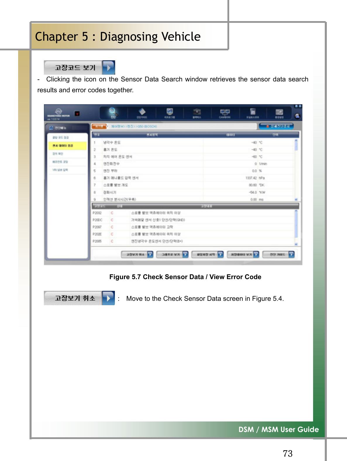
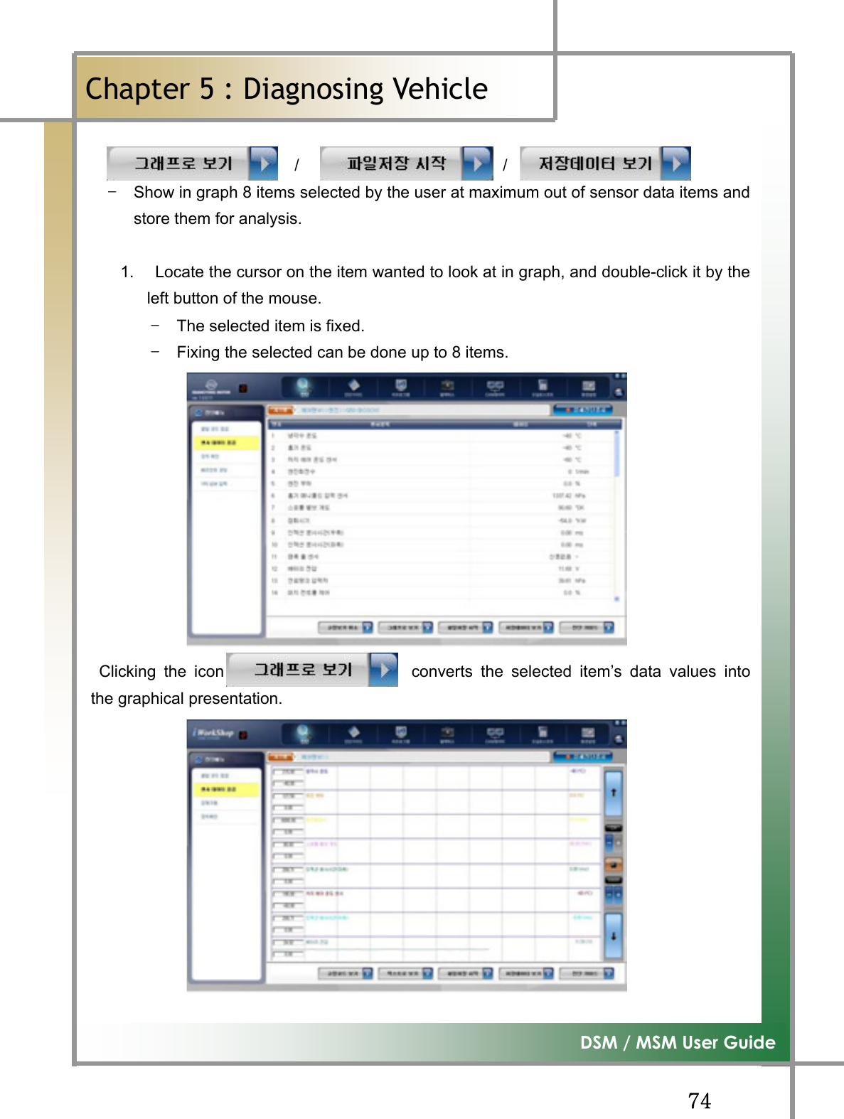
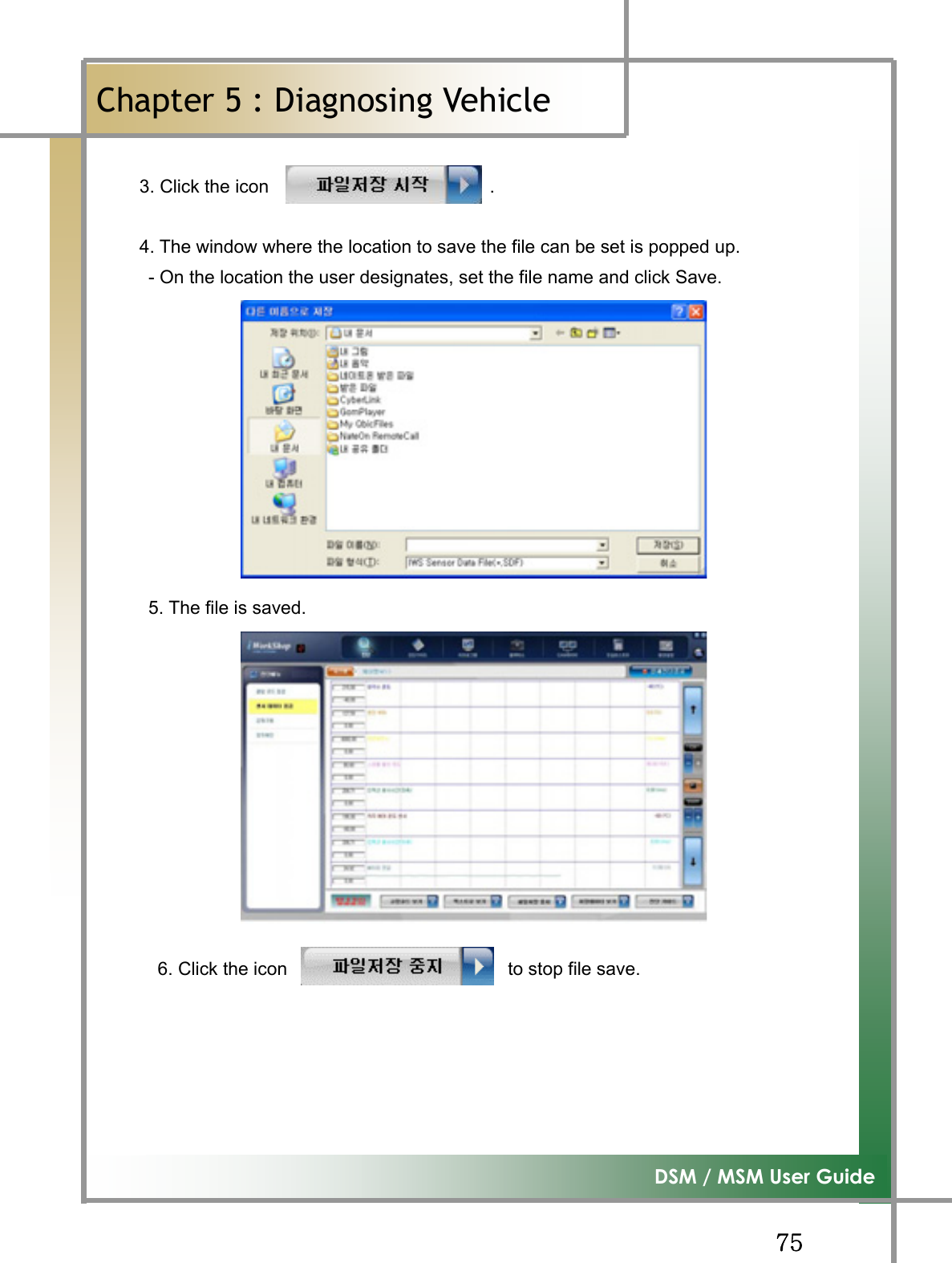
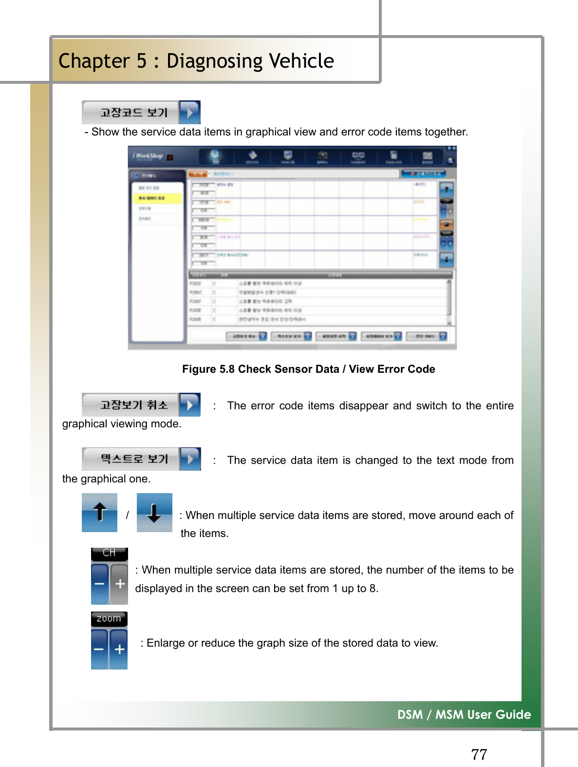
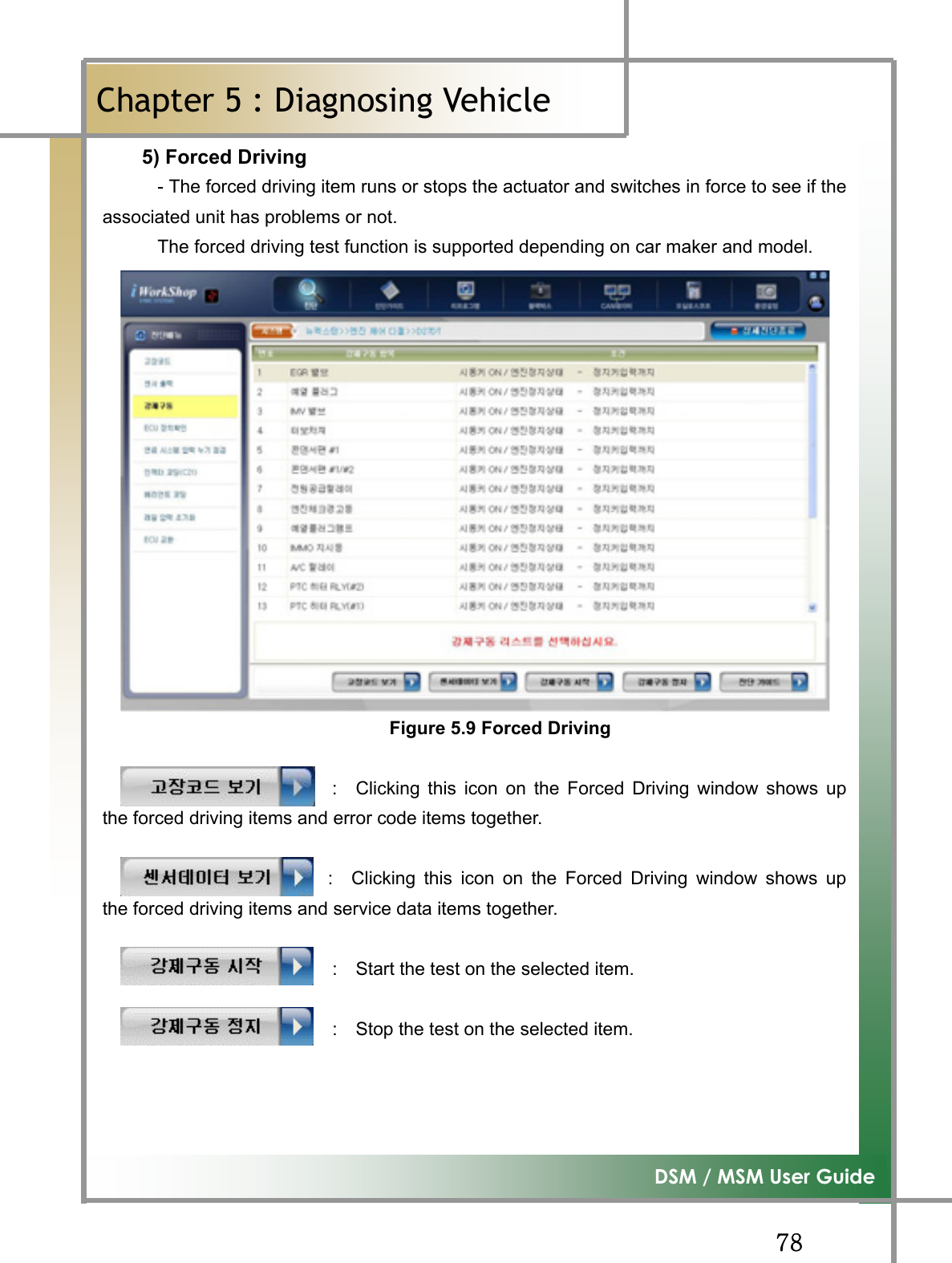
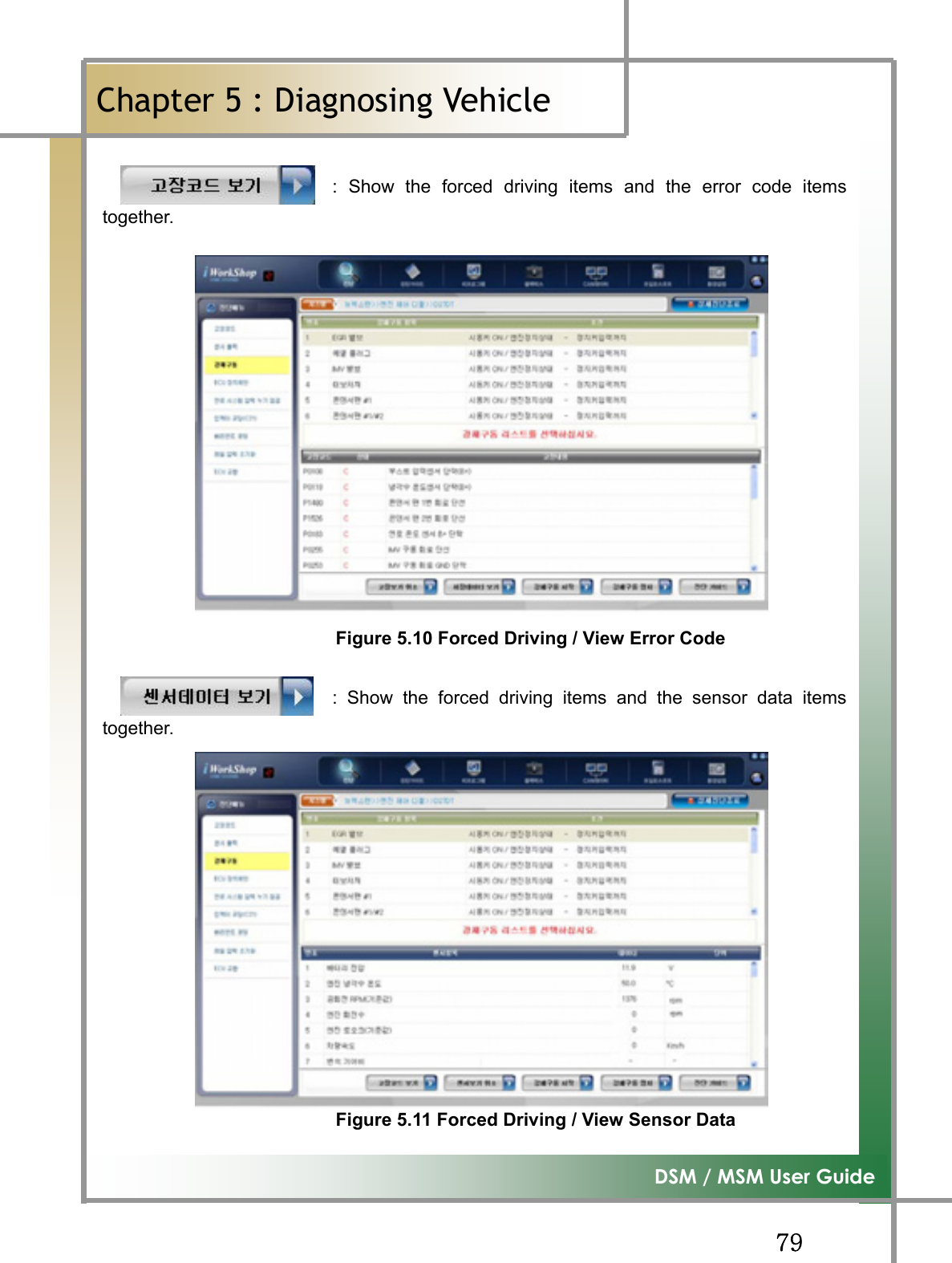
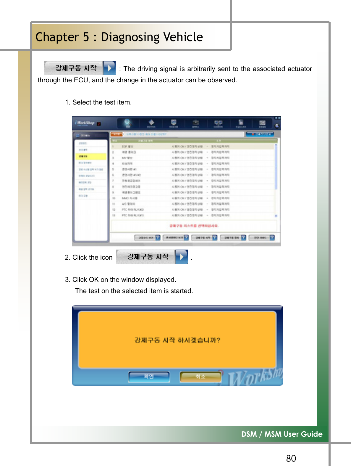
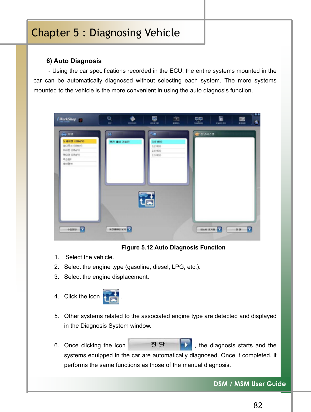
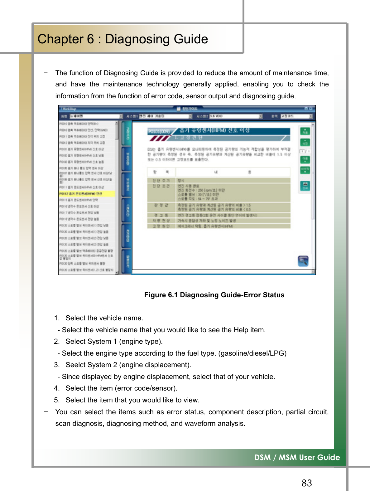
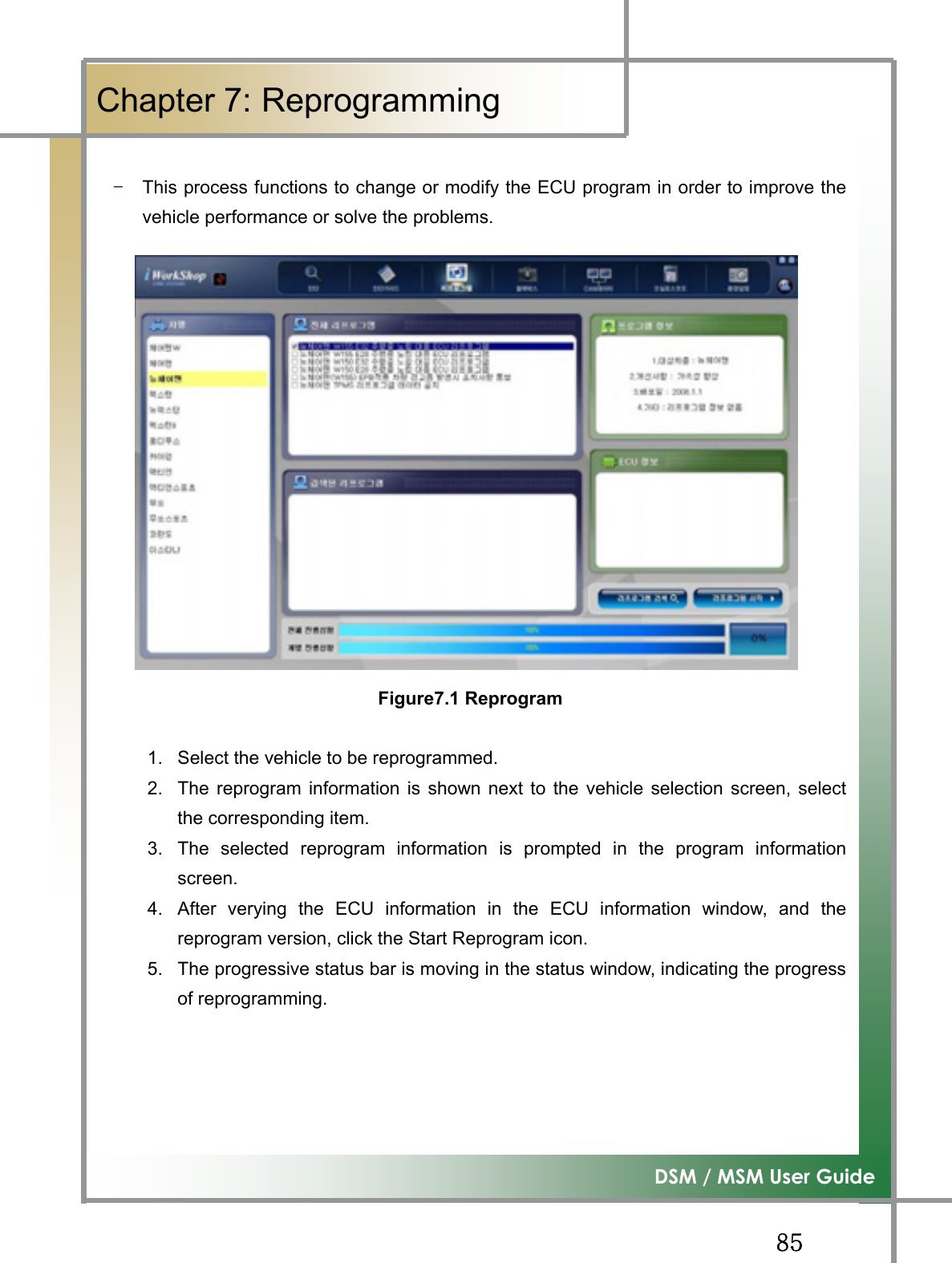
![GG]WG͑DSM / MSM User GuideGChapter 4: Initial ScreenOnce the diagnosing program is run, the screen is displayed as shown in the Figure4.1of Initial Screen, and their individual functions can be described as follows: GGGGGGGGGGG Figure4.1 Initial Screen : To execute the functions of diagnosing vehicle malfunctions, of diagnosing and searching service date, and of operating actuator. : During the diagnosing the vehicle, you can search for the information about Error code, component description on the sensoe data, error status, scan checkup, checking method, and wave form analysis. : To perform the reprogramming work per vehicle. TG When in need of the reprogramming work, the reprogram item is displayed in the screen. : To save the data on the occasion of error occurring through the balckbox switch and analyze it.](https://usermanual.wiki/NEXTECH/DSM.User-manual-2-of-2/User-Guide-998771-Page-2.png)
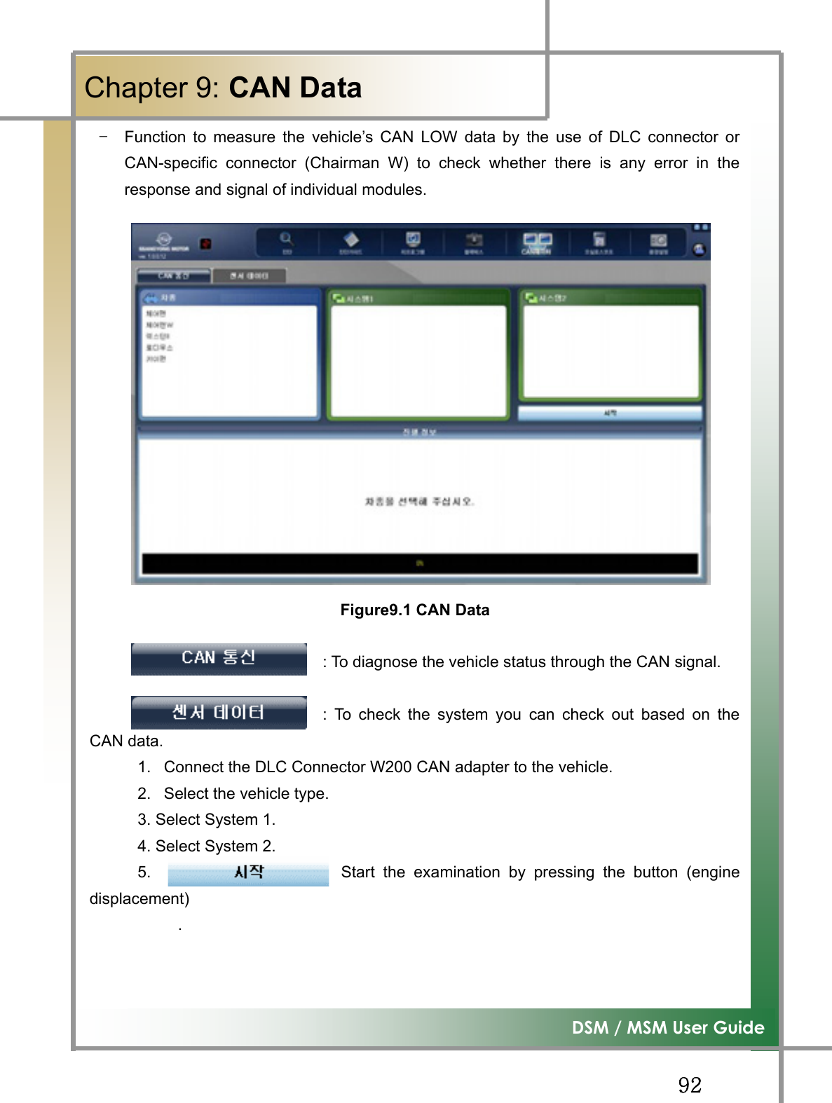
![GG]XG͑DSM / MSM User GuideGChapter 4 : Initial ScreenٻGGGGGGGGGGGGGG: Function to verify the CAN signal that is sent and received on the specific module through the CAN line signal analysis. : Function to measure the wave form, and ignition wave form of individual vehicle sensors. : Function to set the program configurations. GGGGGGGGGGGGGGGGGGGGGG](https://usermanual.wiki/NEXTECH/DSM.User-manual-2-of-2/User-Guide-998771-Page-3.png)
![GG]YG͑DSM / MSM User GuideGChapter 5: Diagnosing Vehicleٻ1. Diagnosis FunctionTG Check any problem in the car. TG Check the service data per sensor. TG Be able to carry out a unit test using the actuator driving function. 1) Select car & system Select System (without subsystem) 2. Select the system. - Depending on the system, it may have thesubsystem. Model Select Window 1. Select the model. Select System (with subsystem)](https://usermanual.wiki/NEXTECH/DSM.User-manual-2-of-2/User-Guide-998771-Page-4.png)
![GG]ZG͑DSM / MSM User GuideGChapter 5 : Diagnosing Vehicleٻ System Select Window Selected System Window 3. After choosing the Select System window to be diagnosed, double-click it with leftbutton of the mouse to pop up the selected system. TG Several systems of the same model can be diagnosed. TIPS) Since it’s possible to diagnose collectively without communicating individualsystems, any problems in the entire systems can be simply checked. * To cancel Select System - To cancel the system selection, select the systemto be canceled by the mouse and double-click it byits left button. - To cancel all the systems selected, click theicon located in the lowerpart of the Diagnosis System box, which initializethe list.](https://usermanual.wiki/NEXTECH/DSM.User-manual-2-of-2/User-Guide-998771-Page-5.png)
![GG][G͑DSM / MSM User GuideGChapter 5 : Diagnosing Vehicleٻ4. Click the button on the lower part of the screen to start thediagnosis for the system selected.](https://usermanual.wiki/NEXTECH/DSM.User-manual-2-of-2/User-Guide-998771-Page-6.png)
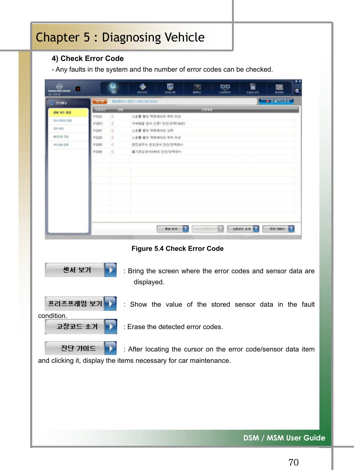
![GG]\G͑DSM / MSM User GuideGChapter 5 : Diagnosing Vehicleٻ2) Diagnosis Results - The diagnosis results for the selected system are displayed in five ways describedbelow. 1. X number of error codes: The communication with the vehicle’s ECU issuccessful, and there are X error codes detected. 2. No error code: The communication with the vehicle’s ECU is successful and noerror code is detected. 3. No response: The communication is tried, but no reply is made by the ECU. 4. Not supported: The communication Is not supported to the system selected. 5. Error code reading error: The communication to the ECU is made, but wrong errorcode(s) were read. Figure5.1 Diagnosis Results with Multiple ECU Connections : Re-diagnose collectively the selected systems. : Eliminate collectively all the error codes of the systems on whichthey are detected. :After selecting the system for which the user wants to eliminatethe error codes, click it to delete them from the selected system.](https://usermanual.wiki/NEXTECH/DSM.User-manual-2-of-2/User-Guide-998771-Page-7.png)
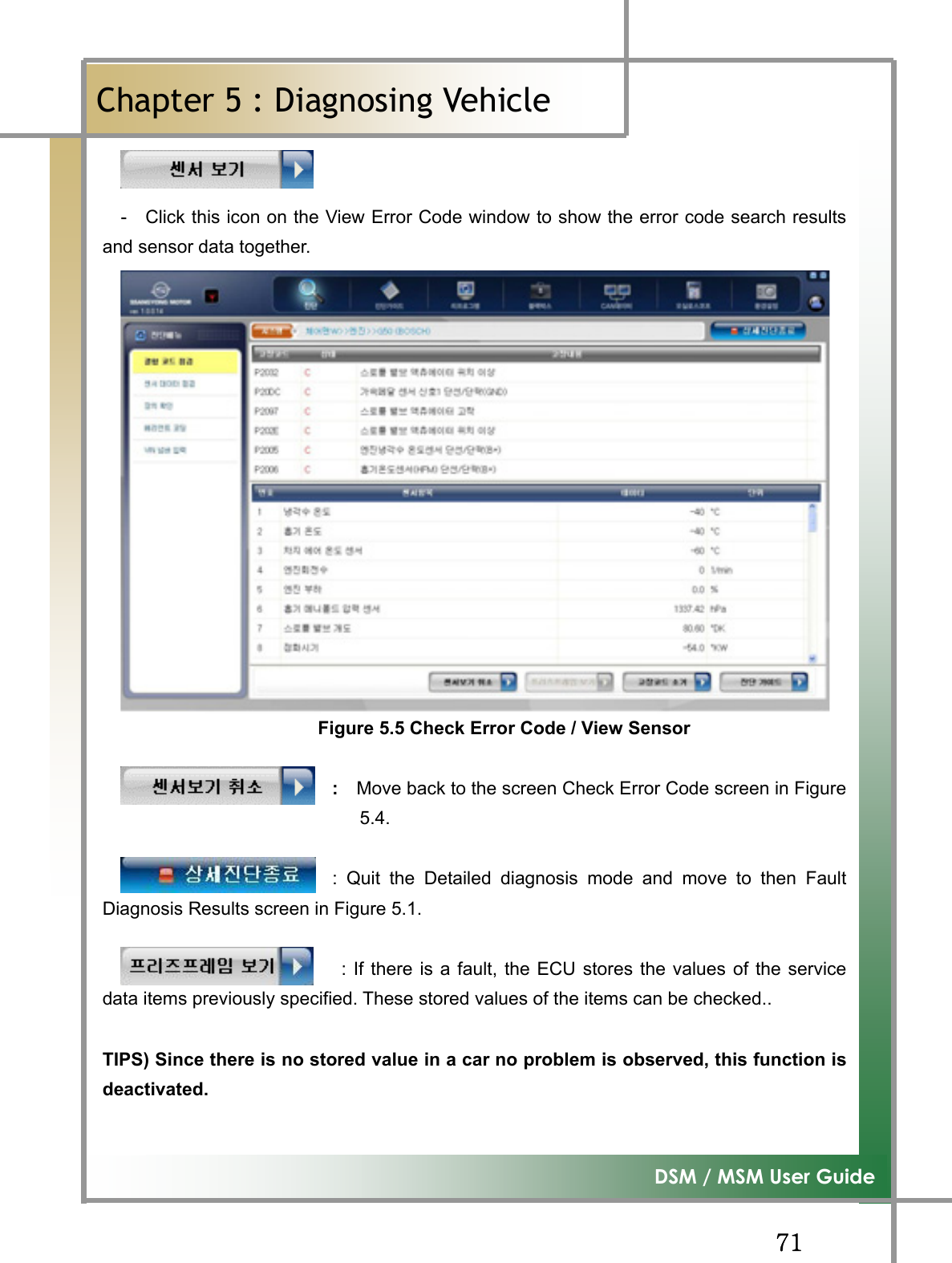
![GG]]G͑DSM / MSM User GuideGChapter 5 : Diagnosing Vehicleٻ* / Function executing TG All error codes of the entire systems the fault diagnosis carried out for are eliminated;the error codes per system can be erased. TG To use the function “Erase All Errors”, click the icon without selecting specific systems,resulted in removing all the error codes. TG To use the function “Erase Error Code”, select the system for which the error codes areerased.Figure 5.2 Erase Error Code Erasing the error codes must be carried out on satisfying the error code eliminating conditions shown as in the screen of Erase Error Code of Figure 5.2. If the conditions are met, the error codes may not be removed. TIPS) Error codes are grouped in two: past error code and current error code. If it is the past error code, executing the erasing command immediatelyerases it and no error codes are detected. If current one, but, executing itimmediately erases the code, but, the error code is promptly detected again.In this case, the erroneous part must be checked and repaired, followed by re-erasing the error code](https://usermanual.wiki/NEXTECH/DSM.User-manual-2-of-2/User-Guide-998771-Page-8.png)
![GG]^G͑DSM / MSM User GuideGChapter 5 : Diagnosing Vehicleٻ : Switch to the screen where functions like error codes, sensoroutput, forced drive, etc. for the selected system can be performed. - Detailed system diagnosis is described in the followingsection. : Move to the previous car selecting screen. When an error code detected, select the associated system todisplay the error code on the Detailed Diagnosis Results window.](https://usermanual.wiki/NEXTECH/DSM.User-manual-2-of-2/User-Guide-998771-Page-9.png)
![GG]_G͑DSM / MSM User’s GuideGChapter 5 : Diagnosing Vehicleٻ3) Detailed System Diagnosis - Functions such as fault diagnosis per system, sensor output, forced drive, devicecheckup, etc. can be carried out. TIPS) If only one system is selected, the following steps are skipped and it movesinto the detailed diagnosis mode. * Diagnosis steps 1. Connect the car’s diagnosis connector and DSM using the main cable. - For details refer to Chapter 3 Connecting to the Car. 2. After selecting the car and the system to be diagnosed in the iWS diagnosisprogram, click the Diagnosis icon. 3. Place the cursor on the system the detailed diagnosis will be carried for. 4. Click the icon by the left button of the mouse. TIPS) Place the mouse cursor on the system the detailed system diagnosis will bedone for, and double-click it by the left button of the mouse to enter into the detailedsystem diagnosis mode.](https://usermanual.wiki/NEXTECH/DSM.User-manual-2-of-2/User-Guide-998771-Page-10.png)
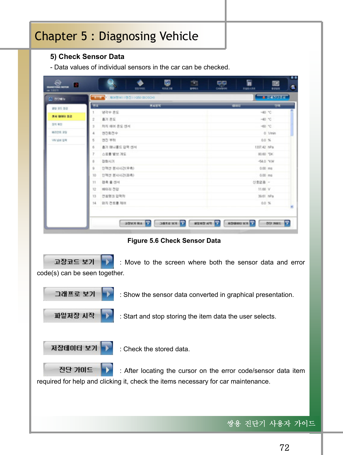
![GG]`G͑DSM / MSM User GuideGChapter 5 : Diagnosing Vehicleٻ5. Once starting the communication with the selected system, the following screen isdisplayed. TG If failed to open the communication, check whether the connection to the car isappropriately made and the correct system is chosen. Figure 5.3 Detailed System Diagnosis Mode](https://usermanual.wiki/NEXTECH/DSM.User-manual-2-of-2/User-Guide-998771-Page-11.png)
![GG^]G͑DSM / MSM User GuideGChapter 5 : Diagnosing Vehicleٻ7. Click the icon . 8. The window View Stored Data is popped up. 9. Click the icon . 10. The window asking the location of stored data is shown up. - Select the location of the stored, and click Open.](https://usermanual.wiki/NEXTECH/DSM.User-manual-2-of-2/User-Guide-998771-Page-18.png)
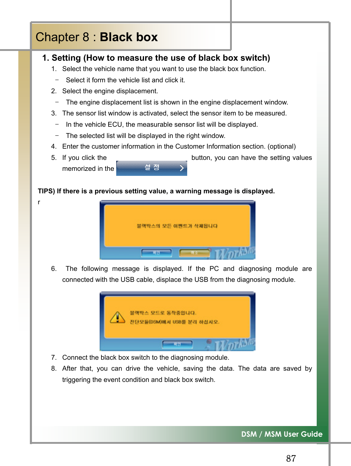
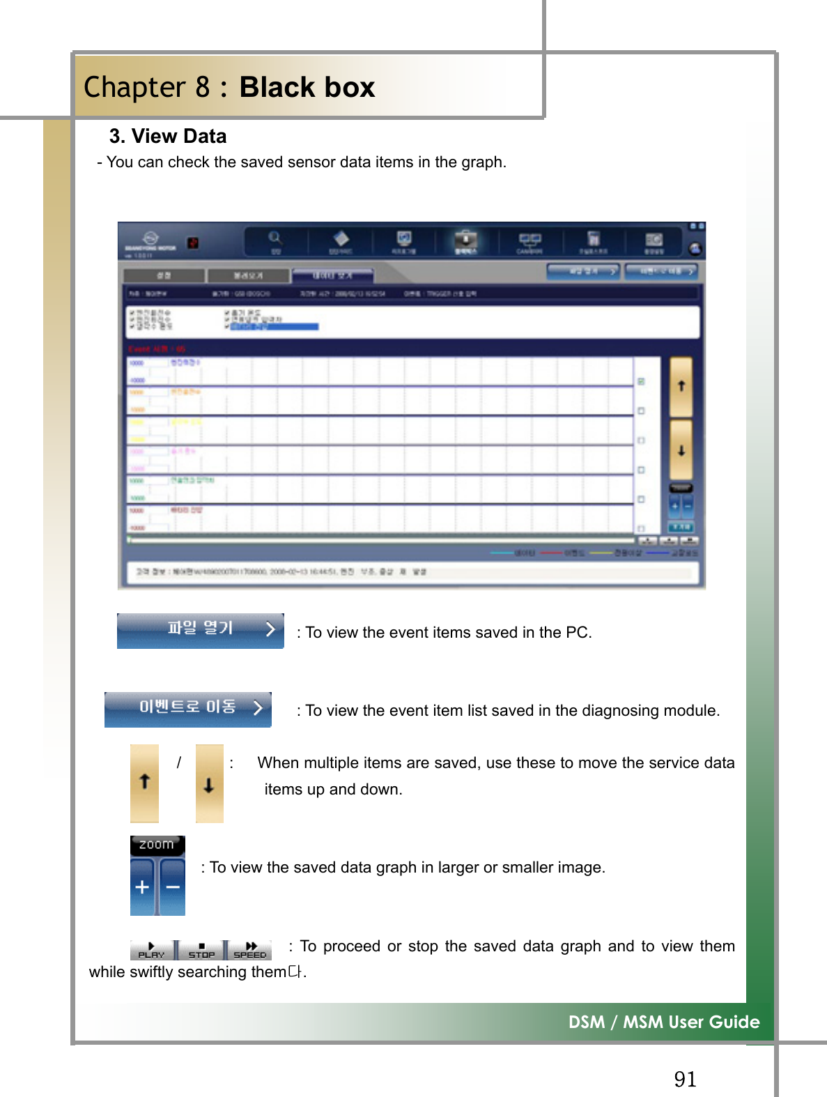
![GG_]G͑DSM / MSM User GuideGChapter 8 : Black BoxTG Function to point to the sensors where you think there may be an error and save the data ofcorresponding items via driving test, and verify it. Figure8.1 Blackbox_Setup : Function to select the items of the vehicle and sensor that performs black box function and set them up. : Function to retrieve the event item stored in thediagnosing module via the black box function : Function to select the stored event item and verify it as the graph type data. : To check the setting values that was previously defined. : After selecting the vehicle and sensor list, click this button to have the setting values memorized.](https://usermanual.wiki/NEXTECH/DSM.User-manual-2-of-2/User-Guide-998771-Page-28.png)
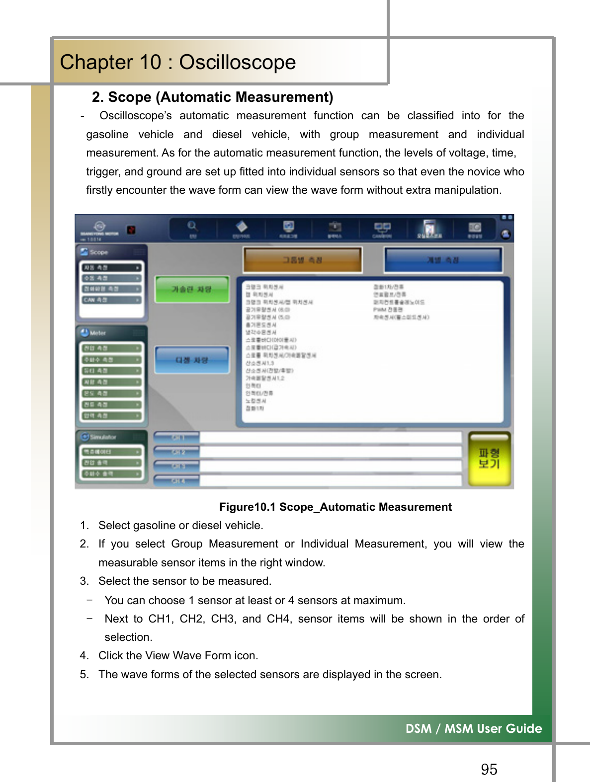
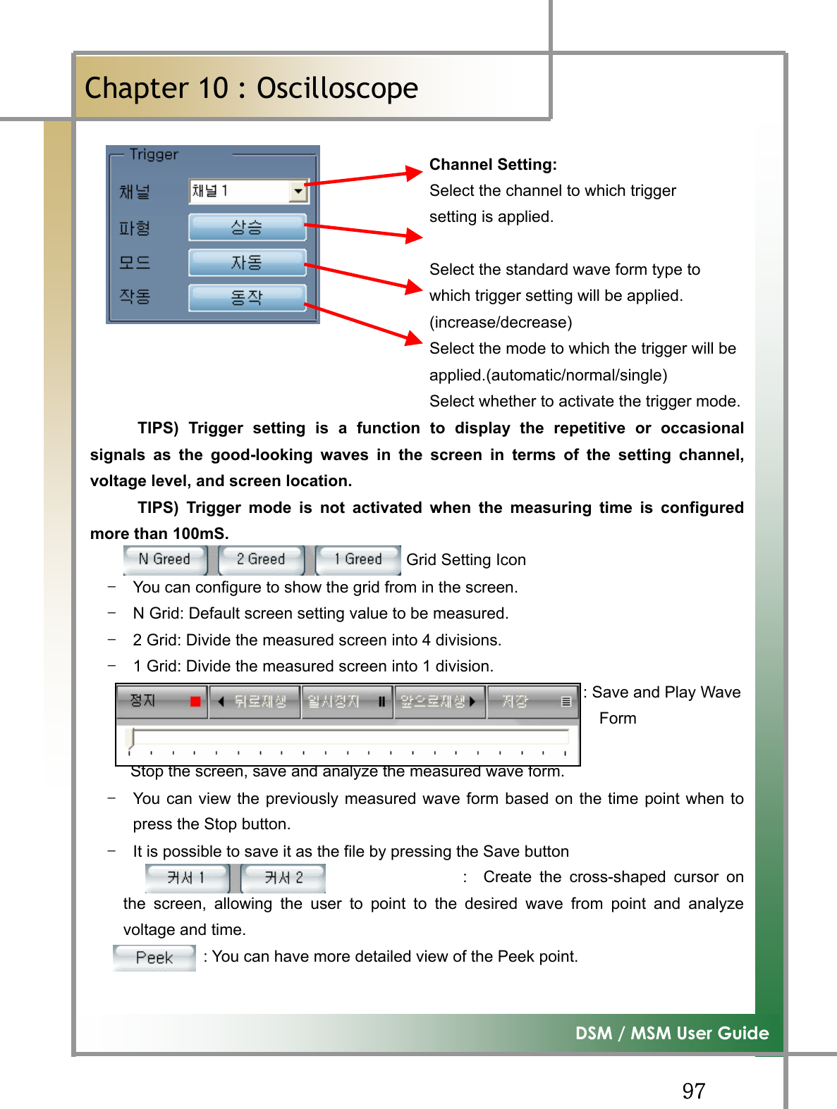
![GG`]G͑DSM / MSM User GuideGChapter 10 : Oscilloscopeٻ3. Scope (Manual Measurement)- You can set the voltage and time values at your convenience to measure the wave form.Figure10.2 Scope_Manual Measurement Display the scope channel. Change measurement into AC or DC. Reverse the wave form by selecting General/Reverse mode Measurement Voltage Setting:To set from 100mV ~ 50V by clicking the left and right arrows. Measuring time setting: To set from 25uS to 10S by clicking the left and right arrows. TIPS) In the grid of the screen, horizontal axis indicates time, and vertical axis isvoltage. Voltage and time setting can be interpreted to set the each scale of thegrid](https://usermanual.wiki/NEXTECH/DSM.User-manual-2-of-2/User-Guide-998771-Page-38.png)
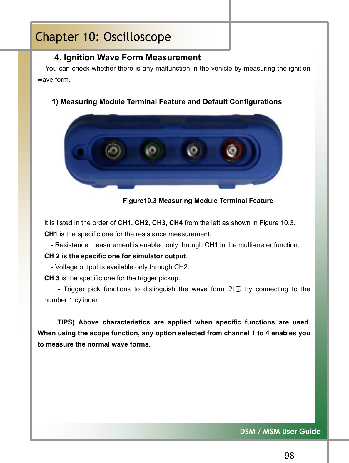
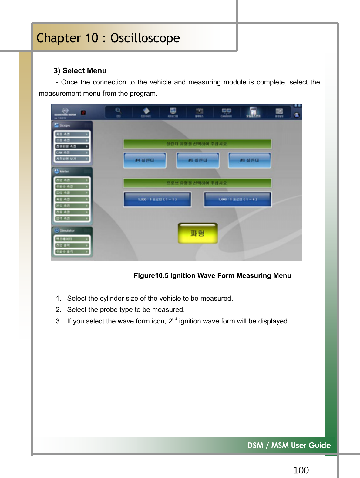
![GG``G͑DSM / MSM User GuideGChapter 10 : OscilloscopeٻGGGGY) Vehicle Connection (DLI ignition method)* Ignition Pickup (1~1) - Connect the 1st ignition pickup linked to the measuring module scope terminalCH1to the high voltage cable of the cylinder to be measured. (used when measuringthe single wave form) * Ignition Pickup (1~4) - Connect the 2nd ignition DLI pickup linked to the measuring module scope terminalCH1 to the high voltage cable of the cylinder that is number 1 and 3, or number 2and 4 of the ignition coil. (used when measuring the single wave form) [Number 1 and 3 High-voltage Cable of Figure 10.4]- Connect the 2nd ignition DLI pickup linked to the measuring module scope terminalCH2 to the high voltage cable of the cylinder that is number 2 and 4, or number 1 and3 of the ignition coil. [Number 2 and 4 High-voltage Cable of Figure 10.4] * Trigger Pickup - To tell the cylinder size, connect to the number 1 cylinder high-voltage cable. - If the number 1 cylinder in the vehicle to be measured is positive polarity, pleaseconnect it to the high voltage cable in the reverse direction of the spark plug. [ Number 1 High-voltage Cable of Figure 10.4]GGGGGGGGGGG Figure10.4 DLI Type](https://usermanual.wiki/NEXTECH/DSM.User-manual-2-of-2/User-Guide-998771-Page-41.png)
![GGXW]͑DSM / MSM User GuideGChapter 10: Oscilloscope7. Simulator - It provides a function to prepare operation condition randomly only for the actuatorsand sensors activated by frequency, duty, and voltage, and check whether it is operated ornot.1) Actuator - You can adjust the frequency and duty to randomly operate actuators with earthcontrol from ECU. Usage example) ISC valve, injector etc. Figure10.10 Simulator_Actuator1. Connect the vehicle and measuring module as shown in the right side of thescreen.2. Adjust the appropriate frequency and duty, and click the Start icon. 3. Verify whether the actuator is in action or not. TIPS) When using the simulator function, be sure to connect the scope channel asdirected by the screen. If the connection is not correctly connected, the functioncannot be realized.](https://usermanual.wiki/NEXTECH/DSM.User-manual-2-of-2/User-Guide-998771-Page-48.png)
![GGXXY͑DSM / MSM User GuideGڬېڼۇۄۏ۔ٻڲڼۍۍڼۉۏ۔ٻxG~GmGwGuG GtGuG G kGGtG G~GwG ~GGGGGGG kGGwG GjG hG G {G G GzGhG hG G {G G GGx u’GGGGGGGGGGGGGtvzmUG Gx pGGSGGGtGGGGGGGGGGGGGGUGx pG G G G G G G G G G SG G G G G G G G GGGGjGGG¡GGUGx ~GGGGGSGGGGGGGUG GGjGsGjGjG GGXUG ~GGGGG GGGGGGGGGGGGGGGGGGGtG{GGGGGGGGGGGGGGGGGGGGGGGGGGGGGGGGGGjGjG~GGSG G yGGG~G XWG G GGwGGGGGGGUG~G XG G GGwGG~G G G GG OSG G G G GG G G G SGG G G G GPG ~G XG G GGmGGGGGwGG wGGGGGGGG~G G G G G G GGGG G tG G GG ’GG GGwGGGGGGGG GkGGGGGGGG wGGGx {GGGGGGGGGGGGGGGGUGGYUG hGxG~GwGGGkG{G jGjG~GGSG G jGyG G~GGGGGGGGG yG G G G G G G G G XWLGOGaGGPG~G G G SG G G G G G G GGGGGGUGGGZUG {GGGGGGGGGGSGGGGGUGGXPG kG G G G G G G G G G G G G G OG G SGGGPGYPG kGGGGGGGG¡GSGGGGGGGGGSGSGGUG GZPG kGGGGGG[PG kGGGGGGGG\PG ~GGGGGGGaGGOGUPG]PG wGGGGGGGG^PG tGGGGGSGGSGGUG_PG kGGGGGG¡GGG G`PG ~GGGGGG“j”GGGG|GnUGGuGlujG}GkG{GZTSGXZGmsGX`^TZZGnTSGnTSGzSGyGGrGX\YTW\WGGjGzaGW_WT`WWT`ZZZGGGGGaVVUTUGX\__T_][YOhVzPG](https://usermanual.wiki/NEXTECH/DSM.User-manual-2-of-2/User-Guide-998771-Page-54.png)
![Type of equipment: Automotive Scanner Brand Name /Trade Mark: Diagnostic System Module Type designation /model: DSM Manufacturer: Nextech Co., Ltd. In accordance with the following Directives: Directive 1999/5/EC Radio Equipment and Telecommunications Terminal Equipment and the mutual recognition of their conformity Including amendments by the CE Marking Directive 1999/5/EC The following harmonized European standards or technical specifications have been applied: Art.3.1.a) EN 60950-1: 2001 + A11:2004 EN 50371 (2002) Art.3.1.b) ETSI EN 301 489-1 V1.6.1 (2005-09) ETSI EN 301 489-17 V1.2.1 (2002-04) Art.3.2) ETSI EN 300 328 V1.7.1 (2006-10) Test report issued by: RF: CTK Co., Ltd. LVD: CTK Co., Ltd.EMC: CTK Co., Ltd. The CE Marking on the products and/or their packaging signifies that Nextech Co., Ltd. hold the reference technical file available to the European Union authorities. Place and date of issue: E&C Venture Dream Tower the 3rd ,13th Floor, 197-33, Guro-Dong, Guro-Gu, Seoul, Korea / SEPTEMBER 02, 2008 [Place, date] EU SEPTEMBER 02, 2008 [Name and signature of person responsible] Young-Hak Kwon /assistant manager](https://usermanual.wiki/NEXTECH/DSM.User-manual-2-of-2/User-Guide-998771-Page-58.png)