Contents
- 1. User manual 1 of 2
- 2. User manual 2 of 2
User manual 2 of 2

G
G
\`G
͑
DSM / MSM User Guide
G
Chapter3: How to Connect to Vehicle
3. Connect DSM to your laptop computer.
TG There are two options of USB and Wireless: you can choose either as you
want.
TG For setting information, please refer to Chapter 2 : How to Install Program.
4. Turn on DSM.
At this time, for the vehicle to which power is not supplied through the
diagnosing connector, if the DSM battery’s charging capacity is not enough, you
must supply additional power. (Vehicle battery, and cigar cable etc.)
5. Select the vehicle and system you would like to diagnose from the vehicle menu,
and then click the “Diagnose” icon.
G
G
G
]WG
͑
DSM / MSM User Guide
G
Chapter 4: Initial Screen
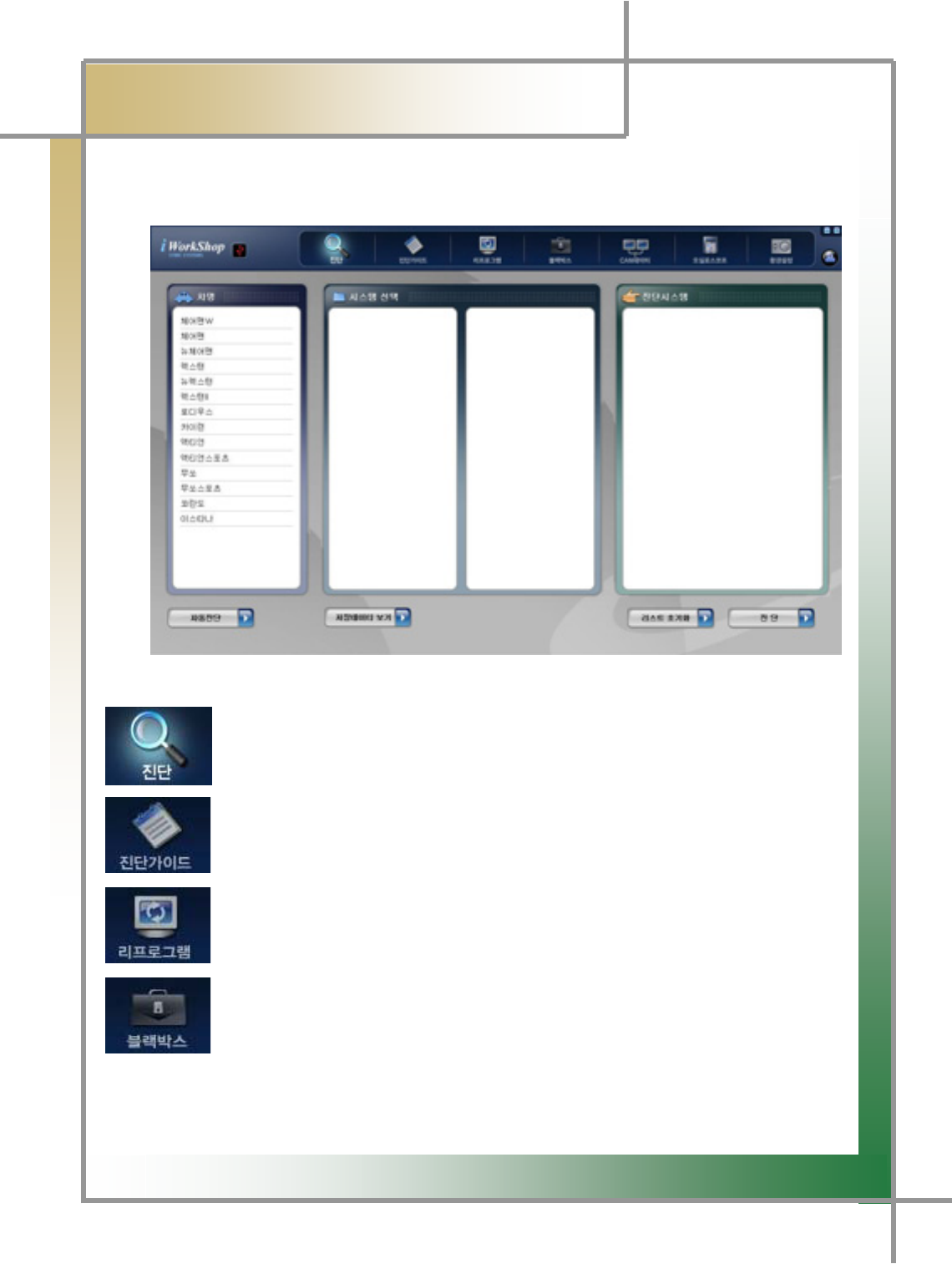
Once the diagnosing program is run, the screen is displayed as shown in the Figure4.1
of Initial Screen, and their individual functions can be described as follows:
G
G
G
G
G
G
G
G
G
G
G
Figure4.1 Initial Screen
: To execute the functions of diagnosing vehicle malfunctions,
of diagnosing and searching service date, and of operating actuator.
: During the diagnosing the vehicle, you can search for the information about
Error code, component description on the sensoe data, error status,
scan checkup, checking method, and wave form analysis.
: To perform the reprogramming work per vehicle.
TG When in need of the reprogramming work, the reprogram item is
displayed in the screen.
: To save the data on the occasion of error occurring through the balckbox
switch and analyze it.

G
G
]XG
͑
DSM / MSM User Guide
G
Chapter 4 : Initial Screenٻ
G
GGGGGGGGGGGGG: Function to verify the CAN signal that is sent and received on the specific
module through the CAN line signal analysis.
: Function to measure the wave form, and ignition wave form of
individual vehicle sensors.
: Function to set the program configurations.
G
G
G
G
G
G
G
G
G
G
G
G
G
G
G
G
G
G
G
G
G
G
G
G
]YG
͑
DSM / MSM User Guide
G
Chapter 5: Diagnosing Vehicleٻ
1. Diagnosis Function
TG Check any problem in the car.
TG Check the service data per sensor.
TG Be able to carry out a unit test using the actuator driving function.
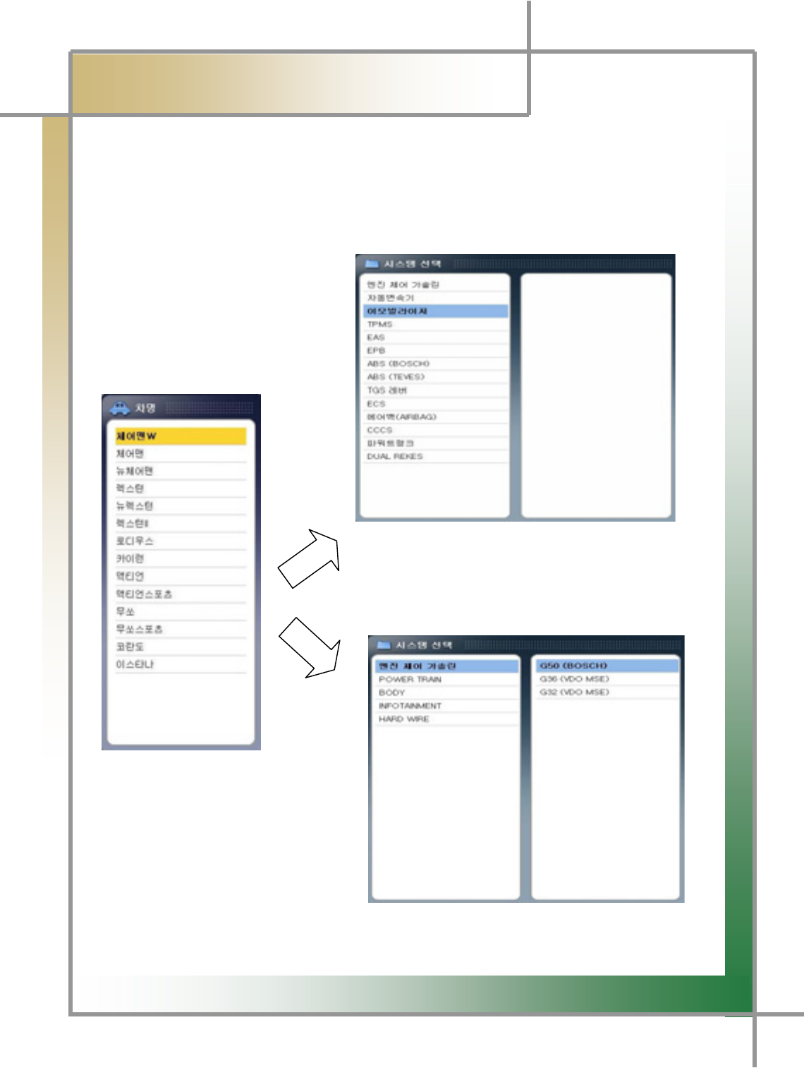
1) Select car & system
Select System (without subsystem)
2. Select the system.
- Depending on the system, it may have the
subsystem.
Model Select Window
1. Select the model.
Select System (with subsystem)
G
G
]ZG
͑
DSM / MSM User Guide
G
Chapter 5 : Diagnosing Vehicleٻ
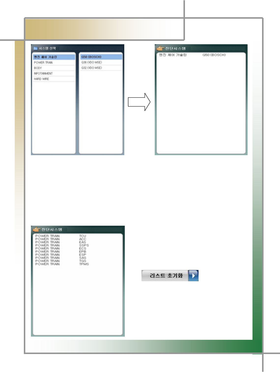
System Select Window Selected System Window
3. After choosing the Select System window to be diagnosed, double-click it with lef
t
button of the mouse to pop up the selected system.
TG Several systems of the same model can be diagnosed.
TIPS) Since it’s possible to diagnose collectively without communicating individual
systems, any problems in the entire systems can be simply checked.
* To cancel Select System
- To cancel the system selection, select the system
to be canceled by the mouse and double-click it by
its left button.
- To cancel all the systems selected, click the
icon located in the lowe
r
part of the Diagnosis System box, which initialize
the list.

G
G
][G
͑
DSM / MSM User Guide
G
Chapter 5 : Diagnosing Vehicleٻ
4. Click the button on the lower part of the screen to start the
diagnosis for the system selected.
G
G
]\G
͑
DSM / MSM User Guide
G
Chapter 5 : Diagnosing Vehicleٻ
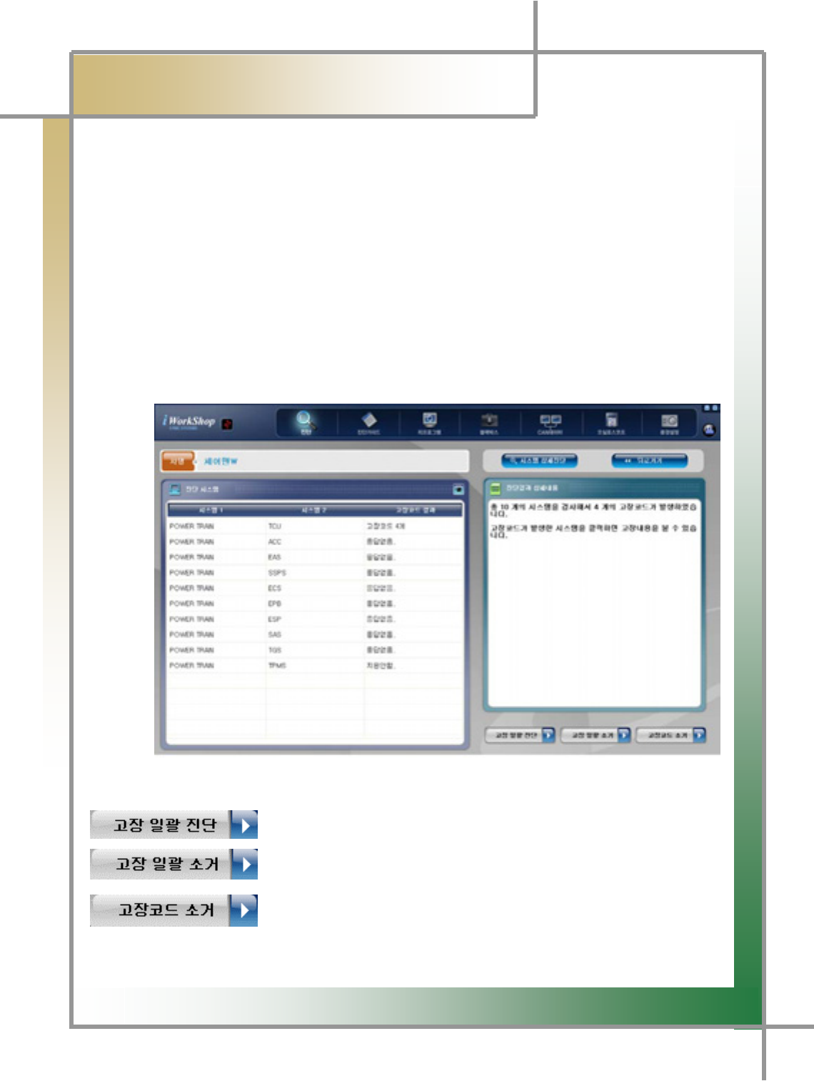
2) Diagnosis Results
- The diagnosis results for the selected system are displayed in five ways described
below.
1. X number of error codes: The communication with the vehicle’s ECU is
successful, and there are X error codes detected.
2. No error code: The communication with the vehicle’s ECU is successful and no
error code is detected.
3. No response: The communication is tried, but no reply is made by the ECU.
4. Not supported: The communication Is not supported to the system selected.
5. Error code reading error: The communication to the ECU is made, but wrong erro
r
code(s) were read.
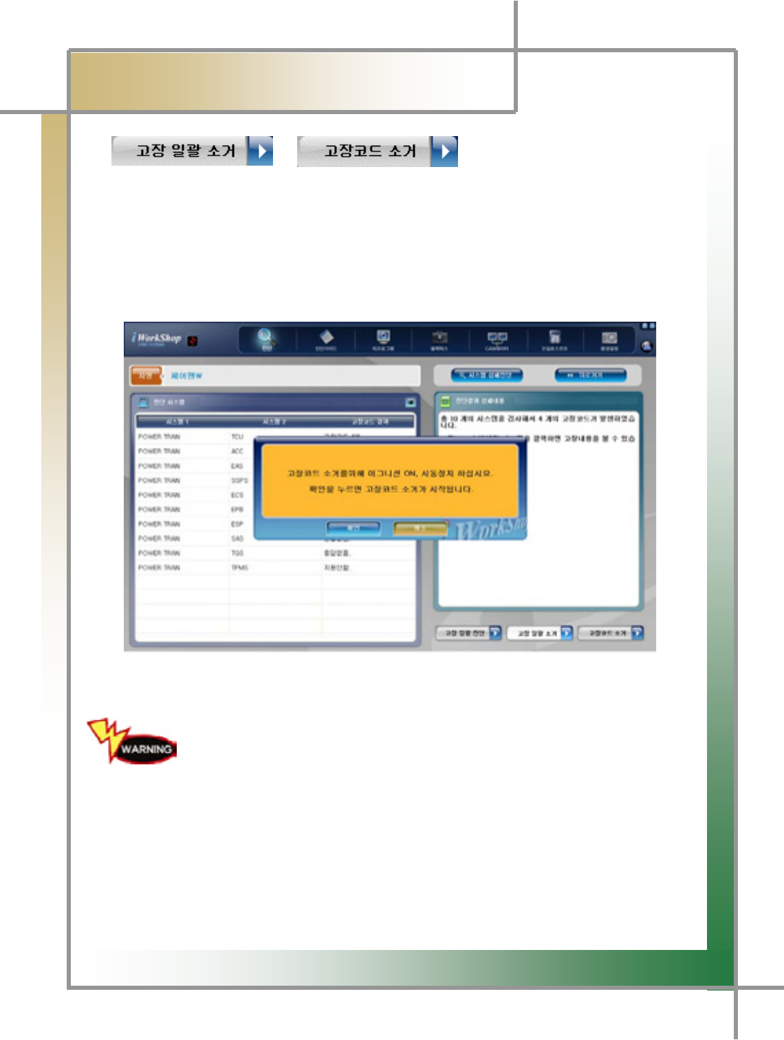
Figure5.1 Diagnosis Results with Multiple ECU Connections
: Re-diagnose collectively the selected systems.
: Eliminate collectively all the error codes of the systems on which
they are detected.
:
A
fter selecting the system for which the user wants to eliminate
the error codes, click it to delete them from the selected system.
G
G
]]G
͑
DSM / MSM User Guide
G
Chapter 5 : Diagnosing Vehicleٻ
* / Function executing
TG All error codes of the entire systems the fault diagnosis carried out for are eliminated;
the error codes per system can be erased.
TG To use the function “Erase All Errors”, click the icon without selecting specific systems,
resulted in removing all the error codes.
TG To use the function “Erase Error Code”, select the system for which the error codes are
erased.
Figure 5.2 Erase Error Code
Erasing the error codes must be carried out on satisfying the error
code eliminating conditions shown as in the screen of Erase Error
Code of Figure 5.2.
If the conditions are met, the error codes may not be removed.
TIPS) Error codes are grouped in two: past error code and current error code.
If it is the past error code, executing the erasing command immediately
erases it and no error codes are detected. If current one, but, executing it
immediately erases the code, but, the error code is promptly detected again.
In this case, the erroneous part must be checked and repaired, followed by re-
erasing the error code
G
G
]^G
͑
DSM / MSM User Guide
G
Chapter 5 : Diagnosing Vehicleٻ
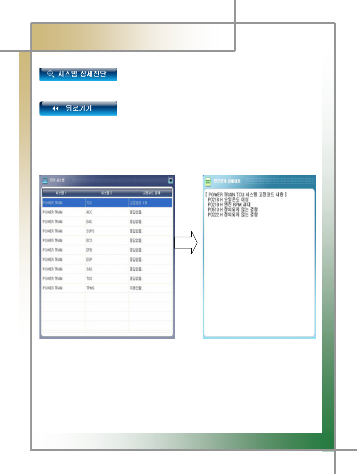
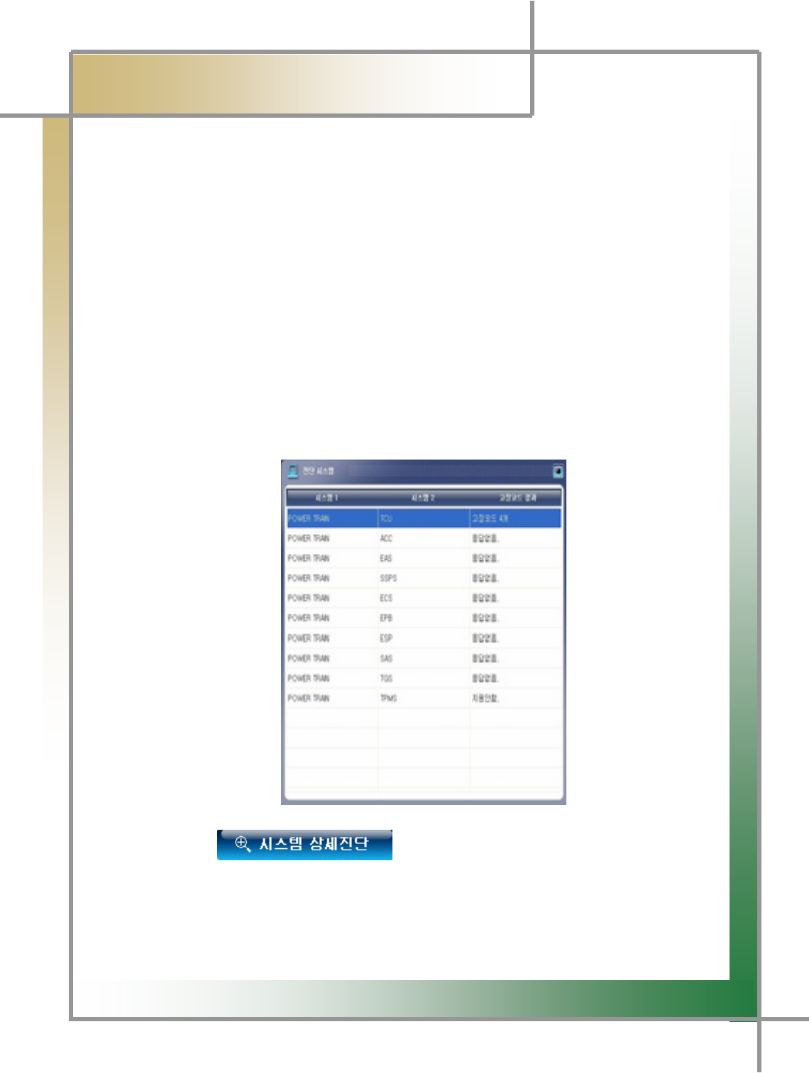
: Switch to the screen where functions like error codes, senso
r
output, forced drive, etc. for the selected system can be performed.
- Detailed system diagnosis is described in the following
section.
: Move to the previous car selecting screen.
When an error code detected, select the associated system to
display the error code on the Detailed Diagnosis Results window.
G
G
]_G
͑
DSM / MSM User’s Guide
G
Chapter 5 : Diagnosing Vehicleٻ
3) Detailed System Diagnosis
- Functions such as fault diagnosis per system, sensor output, forced drive, device
checkup, etc. can be carried out.
TIPS) If only one system is selected, the following steps are skipped and it moves
into the detailed diagnosis mode.
* Diagnosis steps
1. Connect the car’s diagnosis connector and DSM using the main cable.
- For details refer to Chapter 3 Connecting to the Car.
2. After selecting the car and the system to be diagnosed in the iWS diagnosis
program, click the Diagnosis icon.
3. Place the cursor on the system the detailed diagnosis will be carried for.
4. Click the icon by the left button of the mouse.
TIPS) Place the mouse cursor on the system the detailed system diagnosis will be
done for, and double-click it by the left button of the mouse to enter into the detailed
system diagnosis mode.
G
G
]`G
͑
DSM / MSM User Guide
G
Chapter 5 : Diagnosing Vehicleٻ
5. Once starting the communication with the selected system, the following screen is
displayed.
TG If failed to open the communication, check whether the connection to the car is
appropriately made and the correct system is chosen.
Figure 5.3 Detailed System Diagnosis Mode
G
G
^WG
͑
DSM / MSM User Guide
G
Chapter 5 : Diagnosing Vehicleٻ
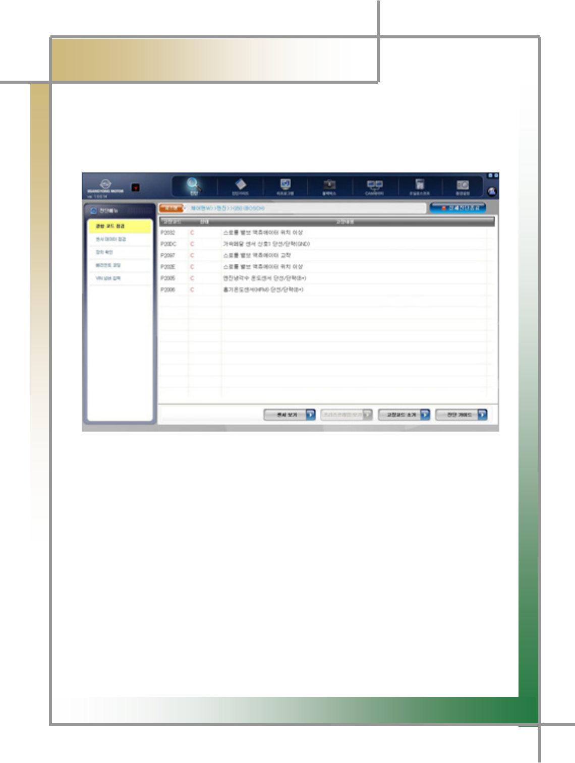
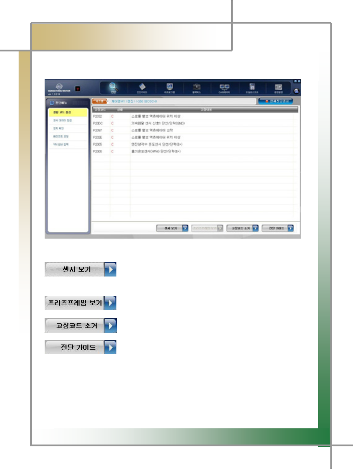
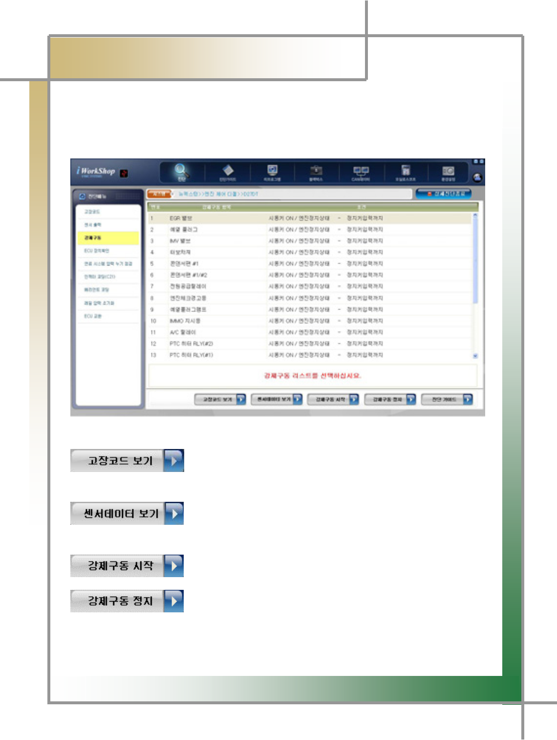
4) Check Error Code
- Any faults in the system and the number of error codes can be checked.
Figure 5.4 Check Error Code
: Bring the screen where the error codes and sensor data are
displayed.
: Show the value of the stored sensor data in the faul
t
condition.
: Erase the detected error codes.
:
A
fter locating the cursor on the error code/sensor data item
and clicking it, display the items necessary for car maintenance.
G
G
^XG
͑
DSM / MSM User Guide
G
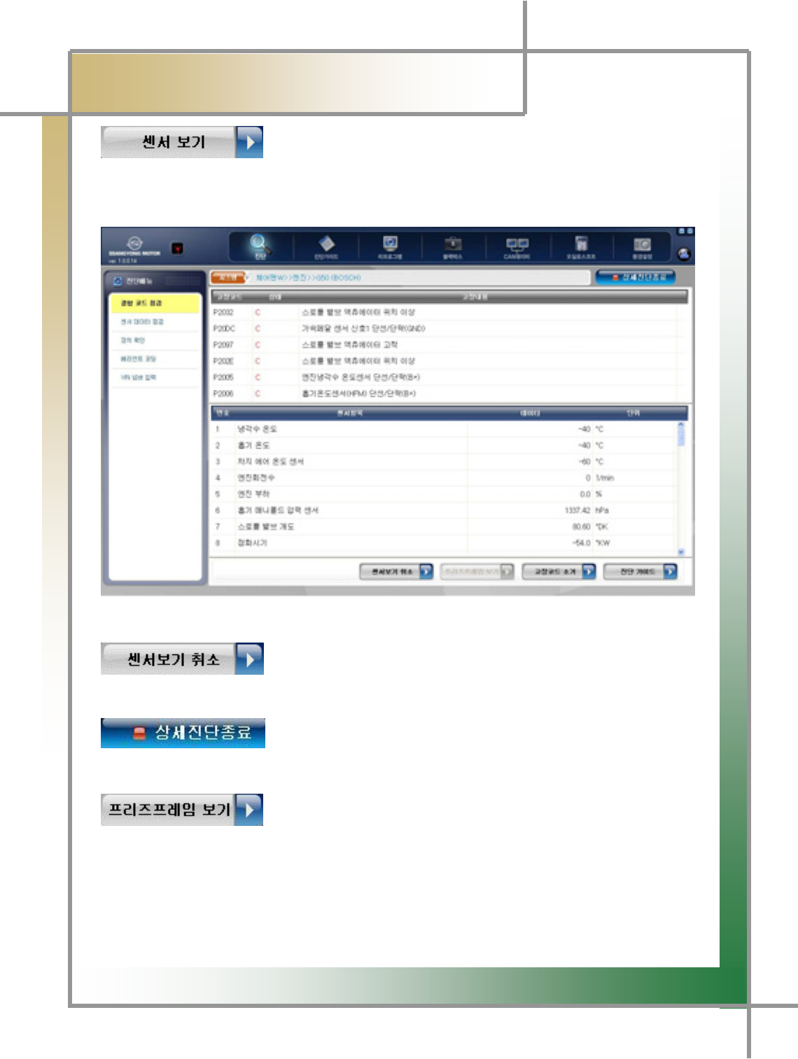
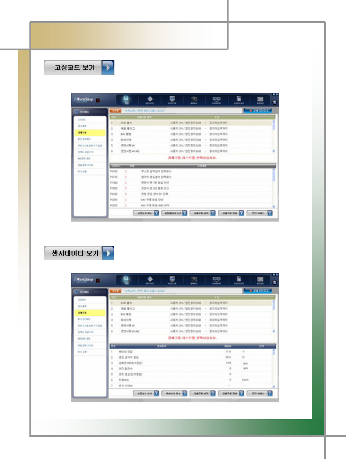
Chapter 5 : Diagnosing Vehicleٻ
- Click this icon on the View Error Code window to show the error code search results
and sensor data together.
Figure 5.5 Check Error Code / View Sensor
: Move back to the screen Check Error Code screen in Figure
5.4.
: Quit the Detailed diagnosis mode and move to then Fault
Diagnosis Results screen in Figure 5.1.
: If there is a fault, the ECU stores the values of the service
data items previously specified. These stored values of the items can be checked..
TIPS) Since there is no stored value in a car no problem is observed, this function is
deactivated.
G
G
^YG
͑
㕣㣿 㰚┾₆ ㌂㣿㧦 Ṗ㧊✲
G
Chapter 5 : Diagnosing Vehicleٻ
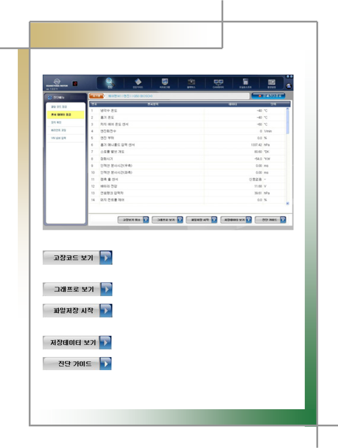
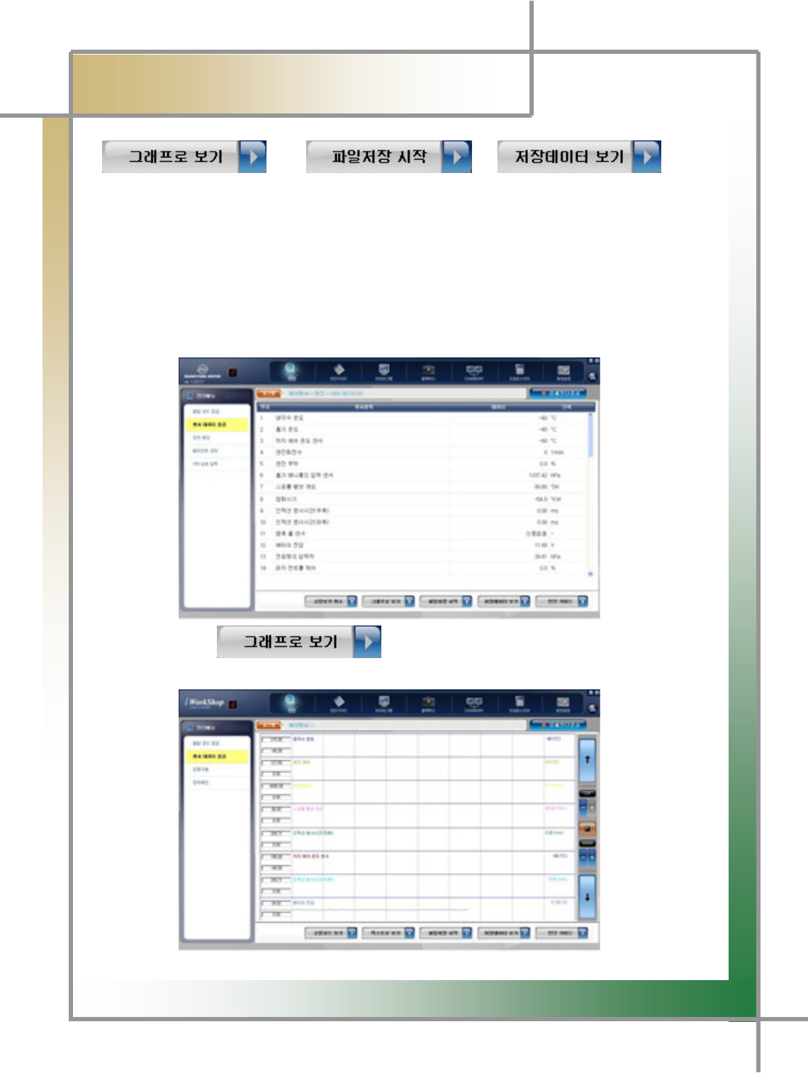
5) Check Sensor Data
- Data values of individual sensors in the car can be checked.
Figure 5.6 Check Sensor Data
: Move to the screen where both the sensor data and erro
r
code(s) can be seen together.
: Show the sensor data converted in graphical presentation.
: Start and stop storing the item data the user selects.
: Check the stored data.
: After locating the cursor on the error code/sensor data item
required for help and clicking it, check the items necessary for car maintenance.
G
G
^ZG
͑
DSM / MSM User Guide
G
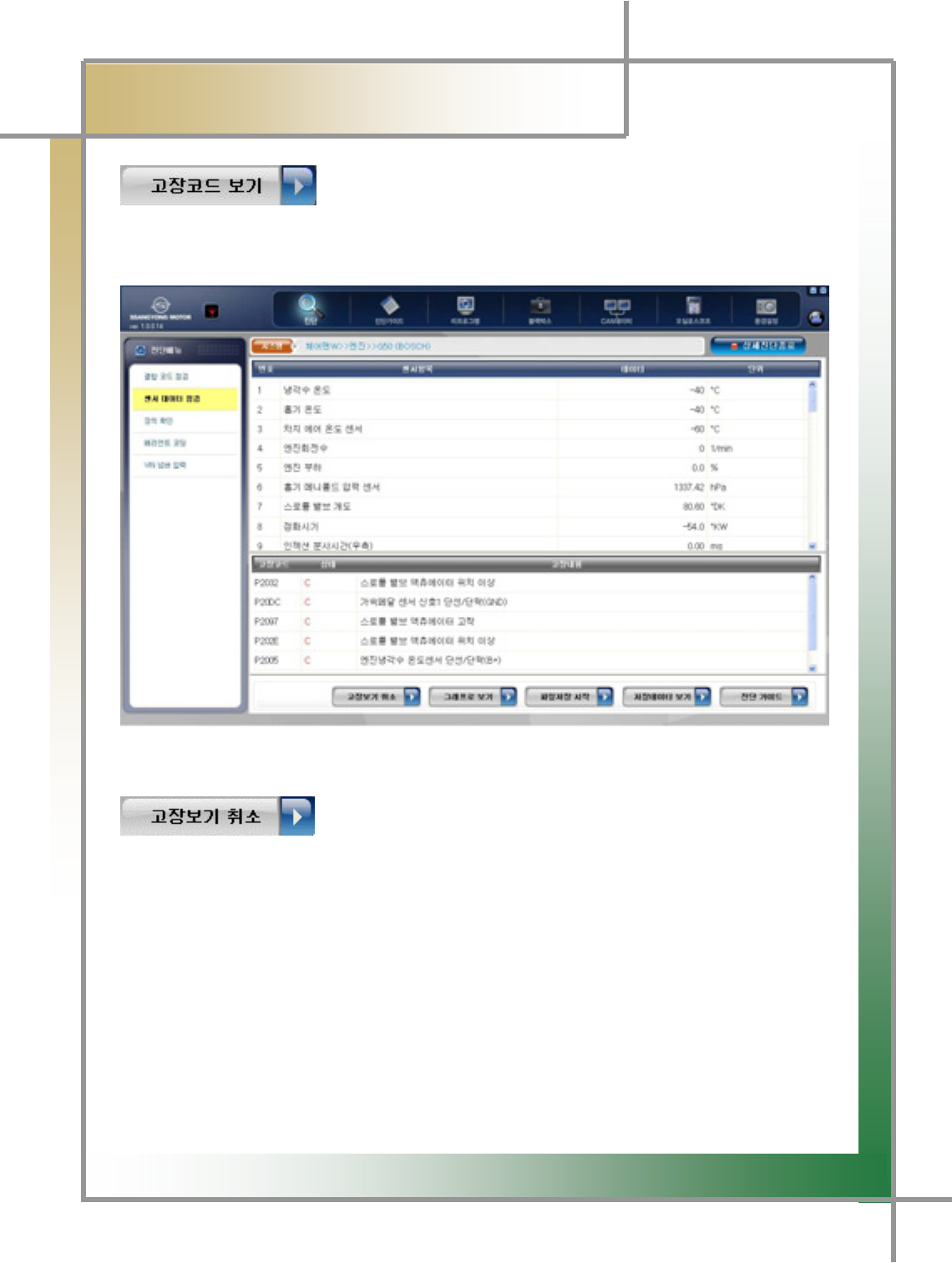
Chapter 5 : Diagnosing Vehicleٻ
- Clicking the icon on the Sensor Data Search window retrieves the sensor data search
results and error codes together.
Figure 5.7 Check Sensor Data / View Error Code
: Move to the Check Sensor Data screen in Figure 5.4.
G
G
^[G
͑
DSM / MSM User Guide
G
Chapter 5 : Diagnosing Vehicleٻ
/ /
TG Show in graph 8 items selected by the user at maximum out of sensor data items and
store them for analysis.
1. Locate the cursor on the item wanted to look at in graph, and double-click it by the
left button of the mouse.
TG The selected item is fixed.
TG Fixing the selected can be done up to 8 items.
Clicking the icon converts the selected item’s data values into
the graphical presentation.
G
G
^\G
͑
DSM / MSM User Guide
G
Chapter 5 : Diagnosing Vehicleٻ
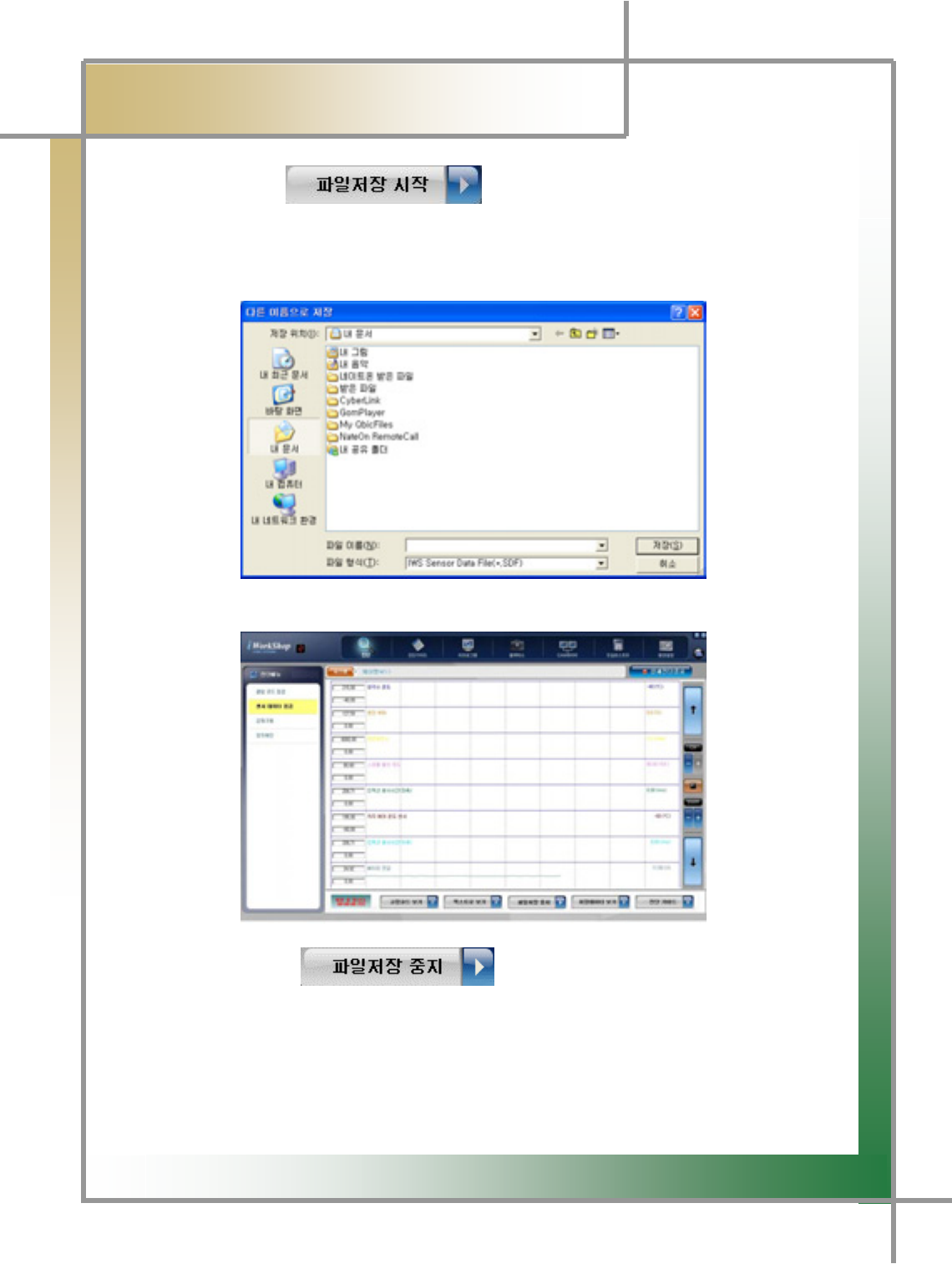
3. Click the icon .
4. The window where the location to save the file can be set is popped up.
- On the location the user designates, set the file name and click Save.
5. The file is saved.
6. Click the icon to stop file save.
G
G
^]G
͑
DSM / MSM User Guide
G
Chapter 5 : Diagnosing Vehicleٻ
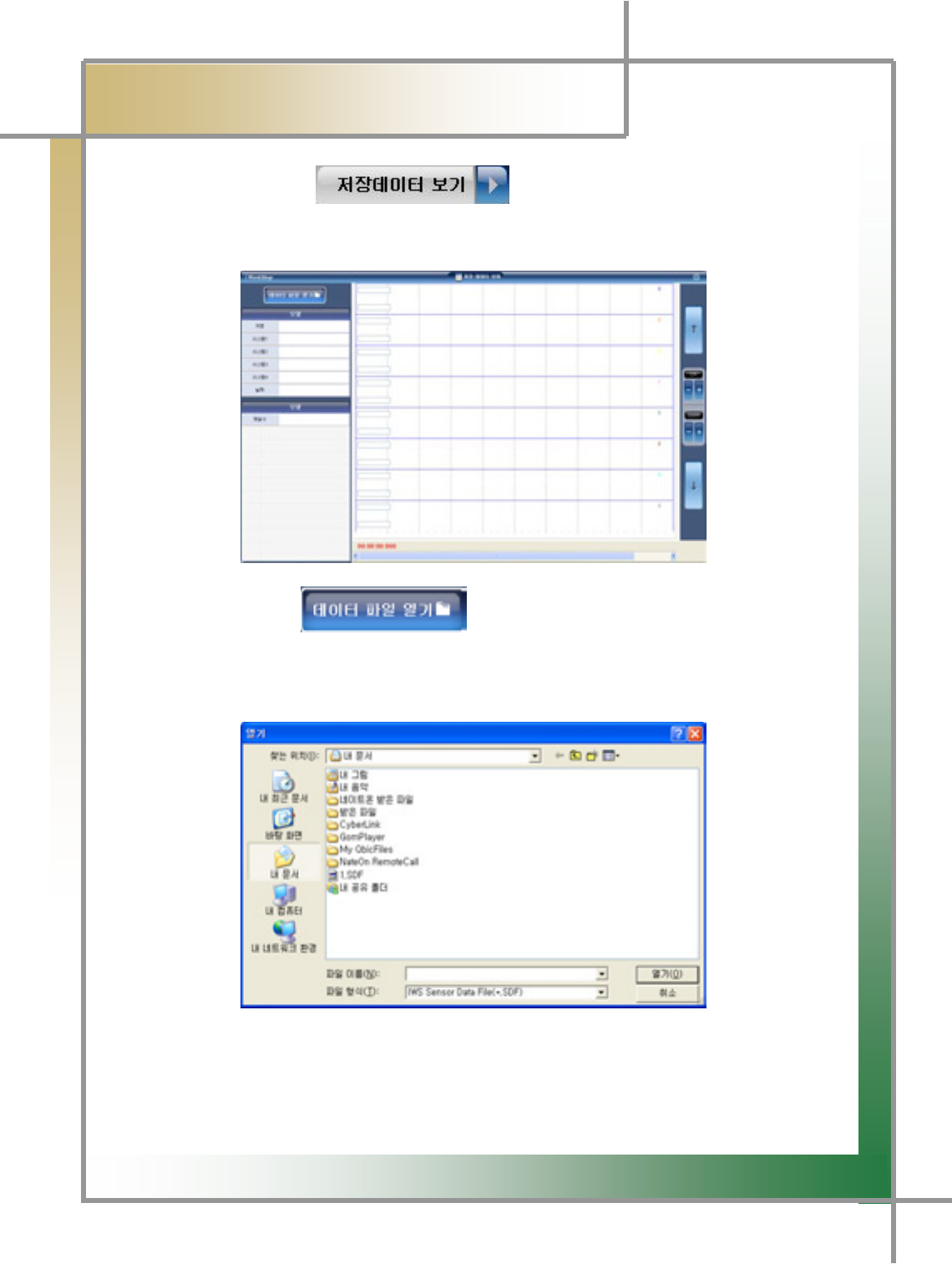
7. Click the icon .
8. The window View Stored Data is popped up.
9. Click the icon .
10. The window asking the location of stored data is shown up.
- Select the location of the stored, and click Open.
G
G
^^G
͑
DSM / MSM User Guide
G
Chapter 5 : Diagnosing Vehicleٻ
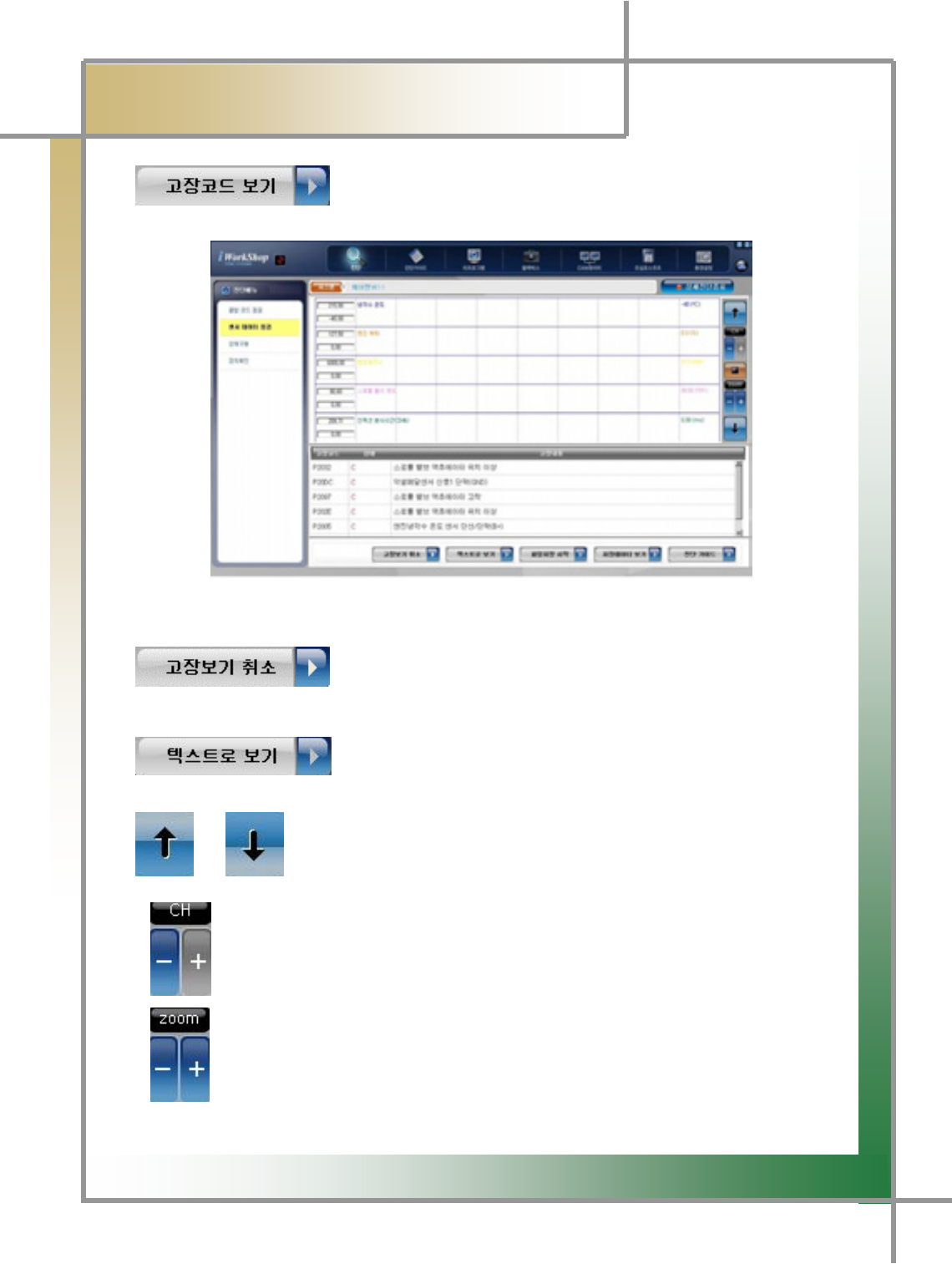
- Show the service data items in graphical view and error code items together.
Figure 5.8 Check Sensor Data / View Error Code
: The error code items disappear and switch to the entire
graphical viewing mode.
: The service data item is changed to the text mode from
the graphical one.
/ : When multiple service data items are stored, move around each of
the items.
: When multiple service data items are stored, the number of the items to be
displayed in the screen can be set from 1 up to 8.
: Enlarge or reduce the graph size of the stored data to view.
G
G
^_G
͑
DSM / MSM User Guide
G
Chapter 5 : Diagnosing Vehicleٻ
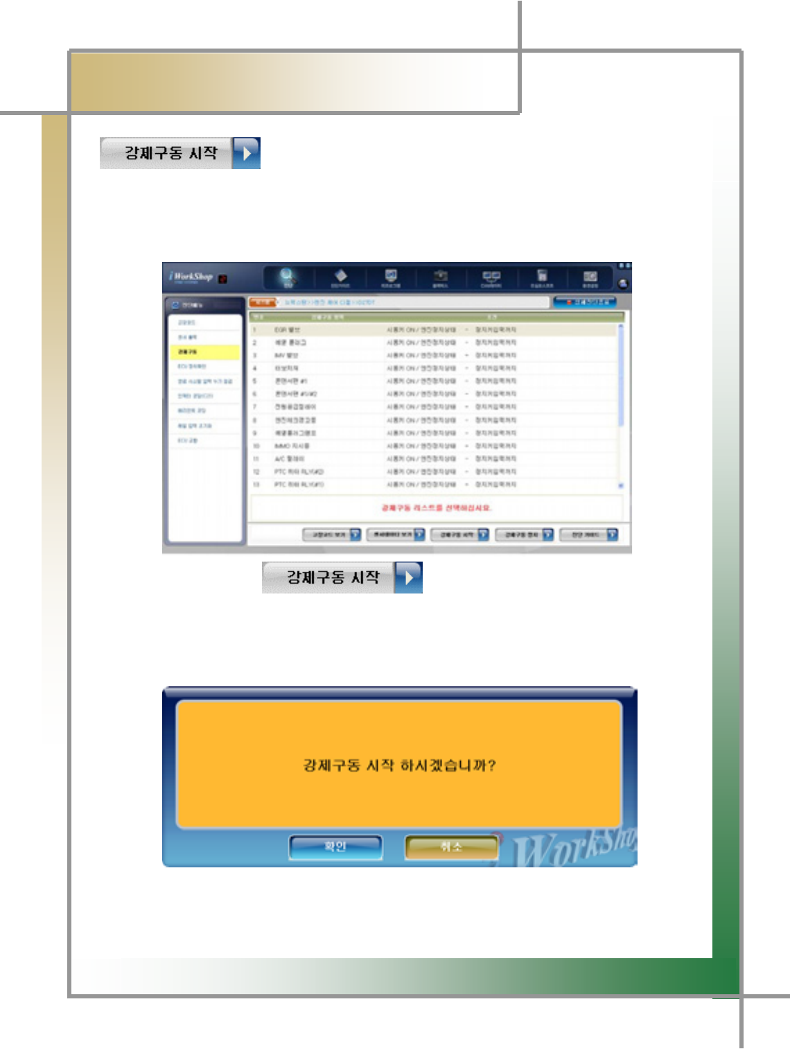
5) Forced Driving
- The forced driving item runs or stops the actuator and switches in force to see if the
associated unit has problems or not.
The forced driving test function is supported depending on car maker and model.
Figure 5.9 Forced Driving
: Clicking this icon on the Forced Driving window shows up
the forced driving items and error code items together.
: Clicking this icon on the Forced Driving window shows up
the forced driving items and service data items together.
: Start the test on the selected item.
: Stop the test on the selected item.
G
G
^`G
͑
DSM / MSM User Guide
G
Chapter 5 : Diagnosing Vehicleٻ
: Show the forced driving items and the error code items
together.
Figure 5.10 Forced Driving / View Error Code
: Show the forced driving items and the sensor data items
together.
Figure 5.11 Forced Driving / View Sensor Data
G
G
_WG
͑
DSM / MSM User Guide
G
Chapter 5 : Diagnosing Vehicleٻ
: The driving signal is arbitrarily sent to the associated actuato
r
through the ECU, and the change in the actuator can be observed.
1. Select the test item.
2. Click the icon .
3. Click OK on the window displayed.
The test on the selected item is started.

G
G
_XG
͑
DSM / MSM User Guide
G
Chapter 5 : Diagnosing Vehicleٻ
4.Clicking the key stops the actuator testing.
TG Clicking this key stops the testing in the middle.
TG Pushing the ESC key or switching the test item by the Ÿ/ź key on the
Carmanskin Lite body frame quits the testing.
TIPS) The evaluation of the actuator test results is done through driving sound o
f
the actuator and switches and change in RPM of the car.
Therefore, the actuator test must be performed in a place where no noise is o
r
it’s quiet if possible.
G
G
_YG
͑
DSM / MSM User Guide
G
Chapter 5 : Diagnosing Vehicleٻ
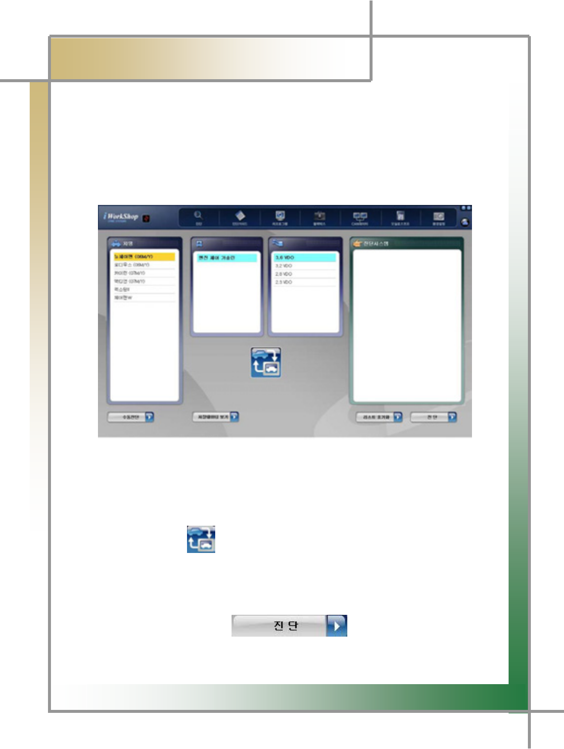
6) Auto Diagnosis
- Using the car specifications recorded in the ECU, the entire systems mounted in the
car can be automatically diagnosed without selecting each system. The more systems
mounted to the vehicle is the more convenient in using the auto diagnosis function.
Figure 5.12 Auto Diagnosis Function
1. Select the vehicle.
2. Select the engine type (gasoline, diesel, LPG, etc.).
3. Select the engine displacement.
4. Click the icon .
5. Other systems related to the associated engine type are detected and displayed
in the Diagnosis System window.
6. Once clicking the icon , the diagnosis starts and the
systems equipped in the car are automatically diagnosed. Once it completed, i
t
performs the same functions as those of the manual diagnosis.
G
G
_ZG
͑ ͑
DSM / MSM User Guide
G
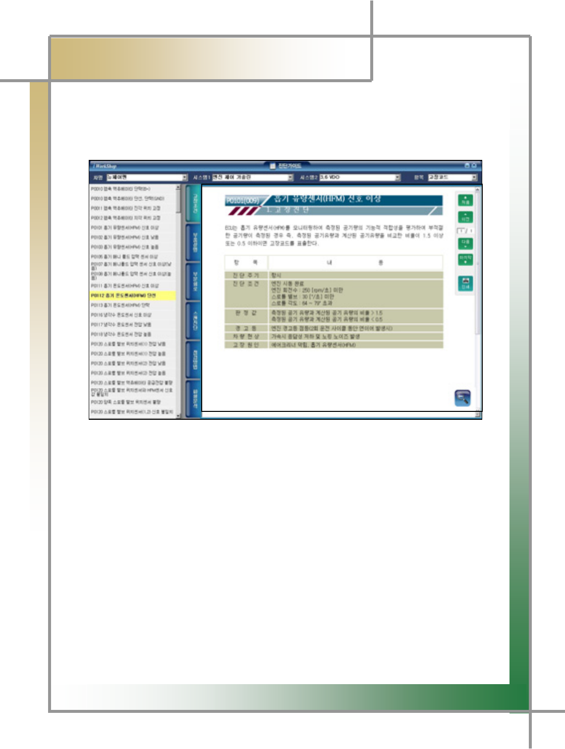
Chapter 6 : Diagnosing Guide
G
TG The function of Diagnosing Guide is provided to reduce the amount of maintenance time,
and have the maintenance technology generally applied, enabling you to check the
information from the function of error code, sensor output and diagnosing guideU
G
G
G
G
G
G
G
G
G
G
G
G
G
G
G
G
Figure 6.1 Diagnosing Guide-Error Status
G
1. Select the vehicle name.
- Select the vehicle name that you would like to see the Help item.
2. Select System 1 (engine type).
- Select the engine type according to the fuel type. (gasoline/diesel/LPG)
3. Seelct System 2 (engine displacement).
- Since displayed by engine displacement, select that of your vehicle.
4. Select the item (error code/sensor).
5. Select the item that you would like to view.
TG You can select the items such as error status, component description, partial circuit,
scan diagnosis, diagnosing method, and waveform analysis.

G
G
_[G
͑
DSM / MSM User Guide
G
Chapter 6 : Diagnosing Guideٻ
G
zFunction Summary by Items
1. Error Status: To check the diagnosis cycle, diagnosing status, decisive value,
whether to turn on warning light, vehicle symptom and error cause.
2. Component Description: To check the mounting location of the error code and the
sensor.
3. Partial Circuit: To check the error code and the circuit diagram of the sensor.
4. Scan Diagnosis: To view the diagnosis methods for the error code
and sensor during the inspection of diagnosis module.
5. Checkup Method: To check the diagnosing methods for the error code and the
sensor.
6. Wave form analysis: To verify the normal wave form of the error code and the
sensor and diagnosing methods.
G
G
G
G
G
G
G
G
G
G
G
G
G
G
G
G
G
G
G
G
G
_\G
͑
DSM / MSM User Guide
G
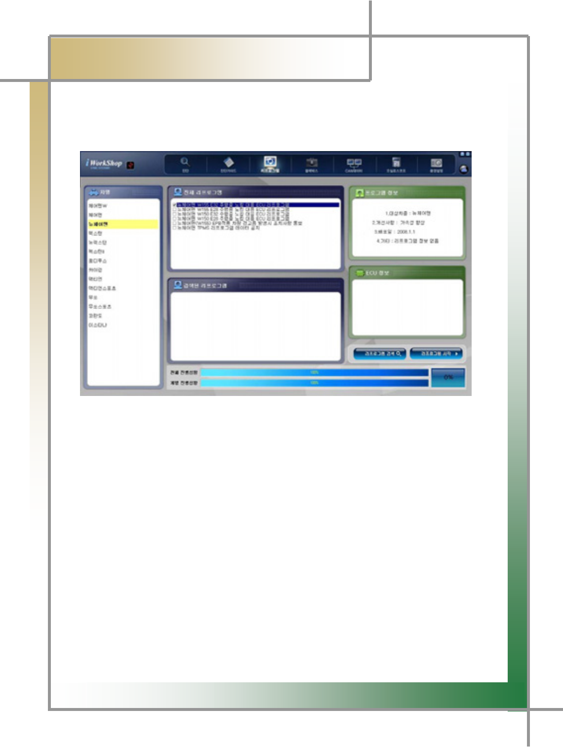
Chapter 7: Reprogramming
GG
TG This process functions to change or modify the ECU program in order to improve the
vehicle performance or solve the problems.
Figure7.1 Reprogram
1. Select the vehicle to be reprogrammed.
2. The reprogram information is shown next to the vehicle selection screen, select
the corresponding item.
3. The selected reprogram information is prompted in the program information
screen.
4. After verying the ECU information in the ECU information window, and the
reprogram version, click the Start Reprogram icon.
5. The progressive status bar is moving in the status window, indicating the progress
of reprogramming.
G
G
_]G
͑
DSM / MSM User Guide
G
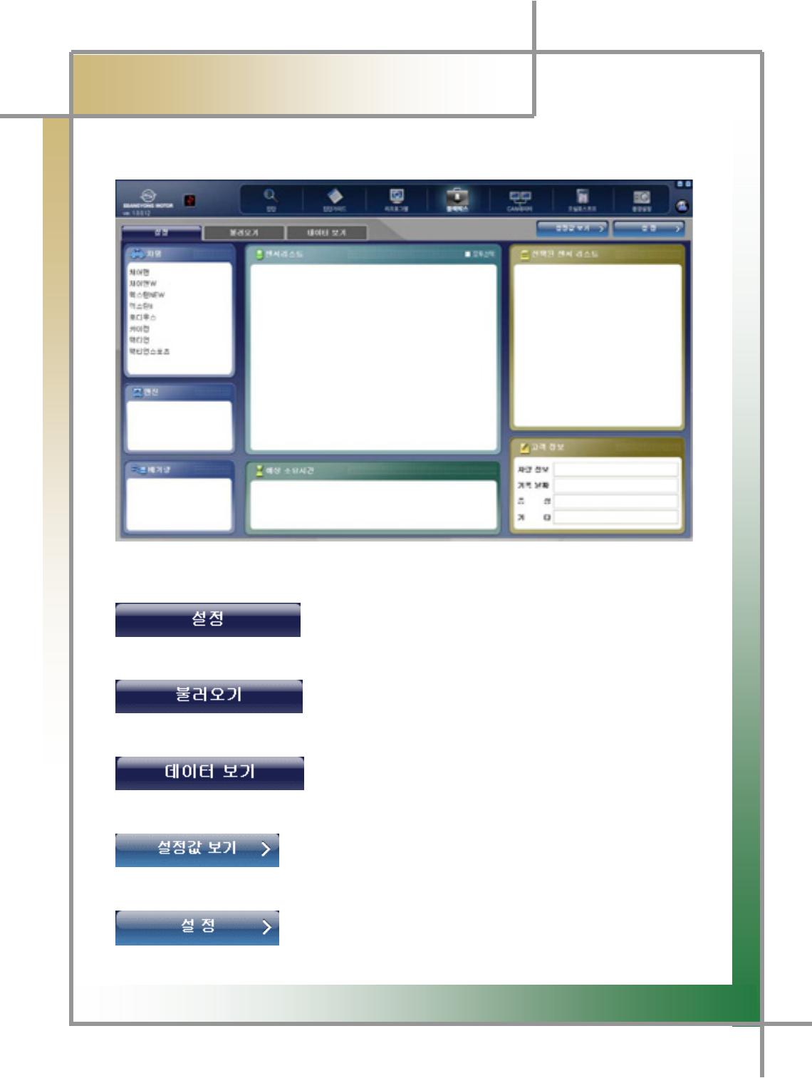
Chapter 8 : Black Box
TG Function to point to the sensors where you think there may be an error and save the data o
f
corresponding items via driving test, and verify it.
Figure8.1 Blackbox_Setup
: Function to select the items of the vehicle and sensor
that performs black box function and set them up.
: Function to retrieve the event item stored in the
diagnosing module via the black box function
: Function to select the stored event item and verify it as
the graph type data.
: To check the setting values that was previously defined.
: After selecting the vehicle and sensor list, click this button to
have the setting values memorized.
G
G
_^G
͑
DSM / MSM User Guide
G
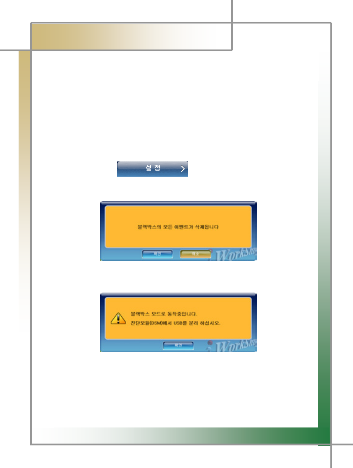
Chapter 8 : Black box
G1. Setting (How to measure the use of black box switch)
1. Select the vehicle name that you want to use the black box function.
TG Select it form the vehicle list and click it.
2. Select the engine displacement.
TG The engine displacement list is shown in the engine displacement window.
3. The sensor list window is activated, select the sensor item to be measured.
TG In the vehicle ECU, the measurable sensor list will be displayed.
TG The selected list will be displayed in the right window.
4. Enter the customer information in the Customer Information section. (optional)
5. If you click the button, you can have the setting values
memorized in the diagnosing modulea.
TIPS) If there is a previous setting value, a warning message is displayed.
r
6. The following message is displayed. If the PC and diagnosing module are
connected with the USB cable, displace the USB from the diagnosing module.
7. Connect the black box switch to the diagnosing module.
8.
A
fter that, you can drive the vehicle, saving the data. The data are saved by
triggering the event condition and black box switch.
G

G
G
__G
͑
DSM / MSM User Guide
G
Chapter 8: Black box
GGGGG
TIPS) As for the date storing function, the date is saved for 10 seconds from
the event occurring point or when to press the black box switch. It is possible
to save the maximum amount of 1 Mbyte, and once the storing process is
complete, the diagnosing module will restart.
9. If you use the USB cable to connect to your PC, reconnect the PC to the diagnosing
module by the use of the USB cable.
10. You can verify the stored data by pressing the Retrieve or View Data button.
TIPS) Black box function can be saved 31 times up to maximum for the setting
items. Also, whenever the saving is completed, the diagnosing module is reset so
that the serial saving is not available. Please understand that.
TIPS) As for the black box function, vehicle status is automatically saved when
vehicle meets the specific condition during the vehicle operation after connecting
the vehicle with problems to the diagnosing module. For the black box storage
condition, please refer to the Black box Event Storing Condition in 89 page.
G
G
G
G
G
G
G
G
G
G
G
G
G
_`G
͑
DSM / MSM Use Guide
G
Chapter 8 : Black box
GGGGG
QGBlackbox Event Storage Condition
Storing Condition Storing Method Symptoms found
in the vehicle
1 When error code occurs Storing 1Mbyte in total
(Sensor, DTC data)
DTC ON
2 Maintain communication with 13V
or less
Storing 1Mbyte in total
(Sensor, power A/D
data)
Engine stopped
during the
operation
3 Maintain the communication after
5 times of trials after
communication stopped with 13V
or lower.
Storing 1Mbyte in total
(Sensor, power A/D
data)
Engine starting
failed due to the
bad power terminal
contact
4 Enter black box switch signal Storing 1Mbyte in total
(Sensor data)
5 When the vehicle RPM drops
down to 400 or lower during the
monitoring of sensor data
Storing 1Mbyte in total
(Sensor, RPM data)
Bad vehicle
condition and
engine starting is
stopped
6 When the voltage drops down to
10V or lower, or the
communication is discontinued
Storing 1Mbyte in total
(Sensor, power A/D
data)
Power shut down
G
G
G
G
G
G
G
G
G
G
`WG
͑
DSM / MSM User Guide
G
Chapter 8 : Black boxٻ
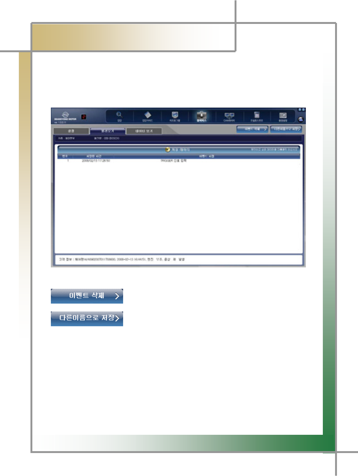
G2. Retrieve
- To check the event items saved in the diagnosing module.
- To save the event stored in the diagnosing module in the user PC.
Figure8.2 な⧯㓺_⩂㡺₆
: To delete the event saved in the diagnosing module.
: To change the name of event saved in the diagnosis module,
and save it in the PC
G
G
G
G
G
G
G
G
G
`XG
͑
DSM / MSM User Guide
G
Chapter 8 : Black boxٻ
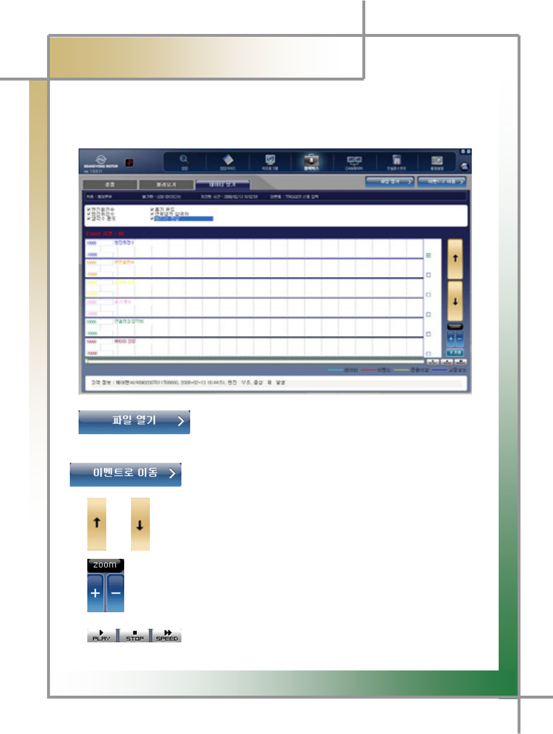
G G 3. View Data
- You can check the saved sensor data items in the graph.
Figure8.3 な⧯㓺_◆㧊䎆 ⽊₆
: To view the event items saved in the PC.
: To view the event item list saved in the diagnosing module.
/ : When multiple items are saved, use these to move the service data
items up and down.
: To view the saved data graph in larger or smaller image.
: To proceed or stop the saved data graph and to view them
while swiftly searching them␘.
G
G
`YG
͑
DSM / MSM User Guide
G
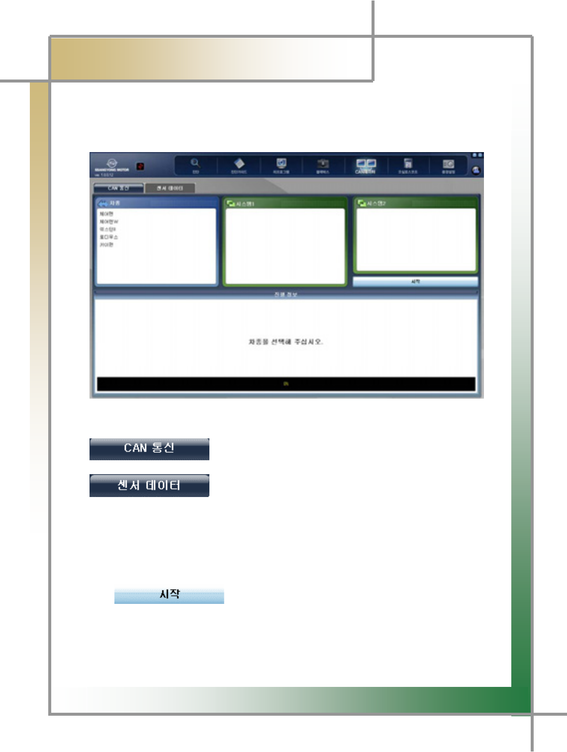
Chapter 9: CAN Data
TG Function to measure the vehicle’s CAN LOW data by the use of DLC connector o
r
CAN-specific connector (Chairman W) to check whether there is any error in the
response and signal of individual modules.
Figure9.1 CAN Data
: To diagnose the vehicle status through the CAN signal.
: To check the system you can check out based on the
CAN data.
1. Connect the DLC Connector W200 CAN adapter to the vehicle.
2. Select the vehicle type.
3. Select System 1.
4. Select System 2.
5. Start the examination by pressing the button (engine
displacement)
.
G
G
`ZG
͑DSM / MSM User Guide
G
Chapter 10: Oscilloscopeٻ
G
TG To use the measuring functions of vehicle’s individual sensors and ignition wave
forms.
TG To perform general multi-meter functions to measure voltage, frequency, duty,
resistance, temperature, and pressure.
To check whether any malfunction occurs in the actuator or software unit through the
actuator operation.
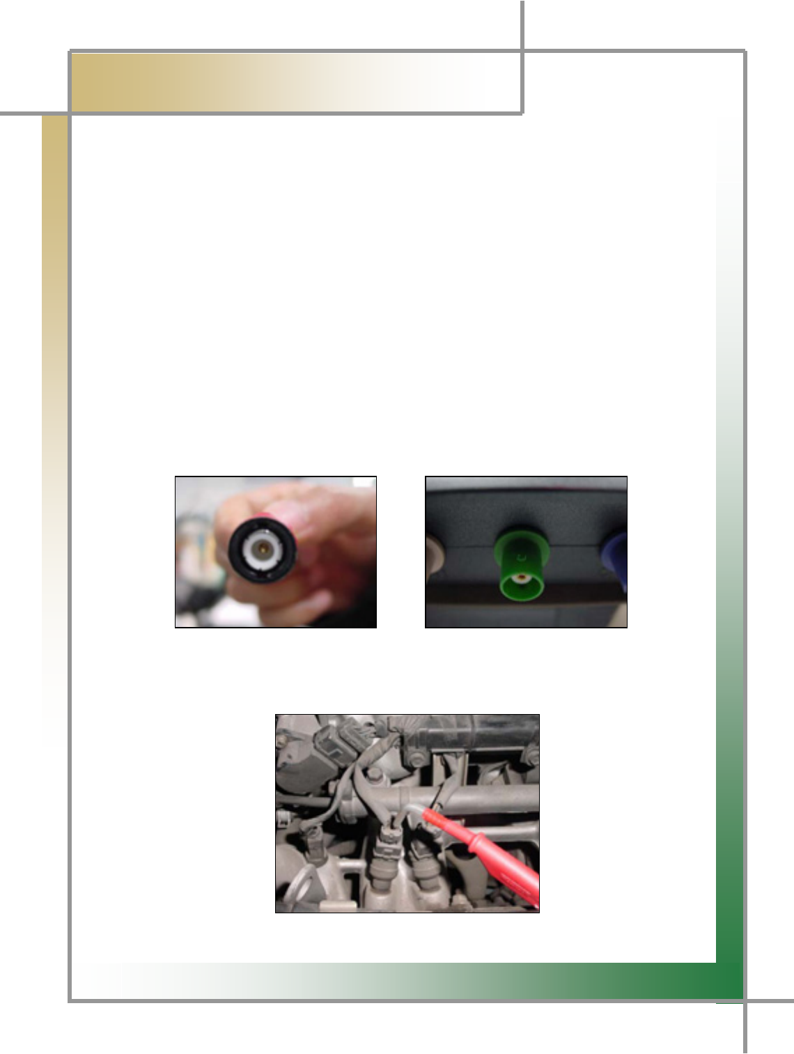
1. Vehicle Connection
1. Connect DSM (measuring module) to the scope cable.
ඖHave the upper and lower groove on the scope cable well aligned with the projected
area of the scope terminal, and then fix it by revolving.
Scope Cable Terminal Measuring Module Scope Terminal
2. Connect the probe to the signal line of the testing vehicle sensor, and have the
tongs snapped into the (-) terminal of the battery.

G
G
`[G
͑
DSM / MSM User Guide
G
Chapter 10: Oscilloscopeٻ
G
TIPS) Generally speaking, the vehicle sensor wiring comprises of power supply
line, grounding wire, and signal line. And signal line is connected to the vehicle ECU,
sending and receiving the signal. Oscilloscope-based test is to check the wave form
using this signal line.
G
G
G
G
G
G
G
GG
GGG
G
G
G
G
G
G
G
G
G
G
G
G
G
G
G
G
G
G
G
G
G
`\G
͑
DSM / MSM User Guide
G
Chapter 10 : Oscilloscope
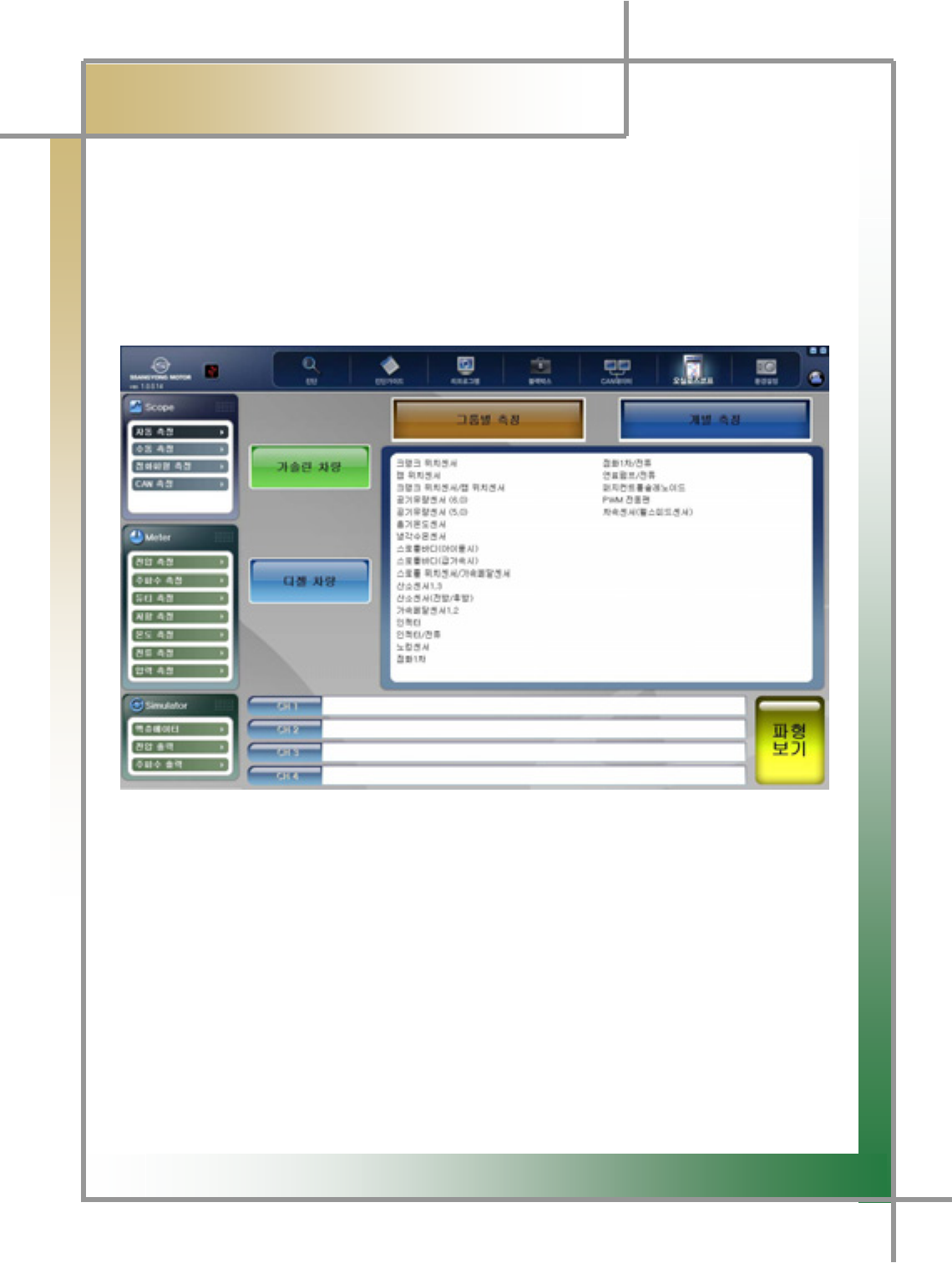
2. Scope (Automatic Measurement)
- Oscilloscope’s automatic measurement function can be classified into for the
gasoline vehicle and diesel vehicle, with group measurement and individual
measurement. As for the automatic measurement function, the levels of voltage, time,
trigger, and ground are set up fitted into individual sensors so that even the novice who
firstly encounter the wave form can view the wave form without extra manipulation.
G
G
G
G
G
G
G
G
G
G
G
G
G
G
G
Figure10.1 Scope_Automatic Measurement
1. Select gasoline or diesel vehicle.
2. If you select Group Measurement or Individual Measurement, you will view the
measurable sensor items in the right window.
3. Select the sensor to be measured.
TG You can choose 1 sensor at least or 4 sensors at maximum.
TG Next to CH1, CH2, CH3, and CH4, sensor items will be shown in the order o
f
selection.
4. Click the View Wave Form icon.
5. The wave forms of the selected sensors are displayed in the screen.
GG
G
G
`]G
͑
DSM / MSM User Guide
G
Chapter 10 : Oscilloscopeٻ
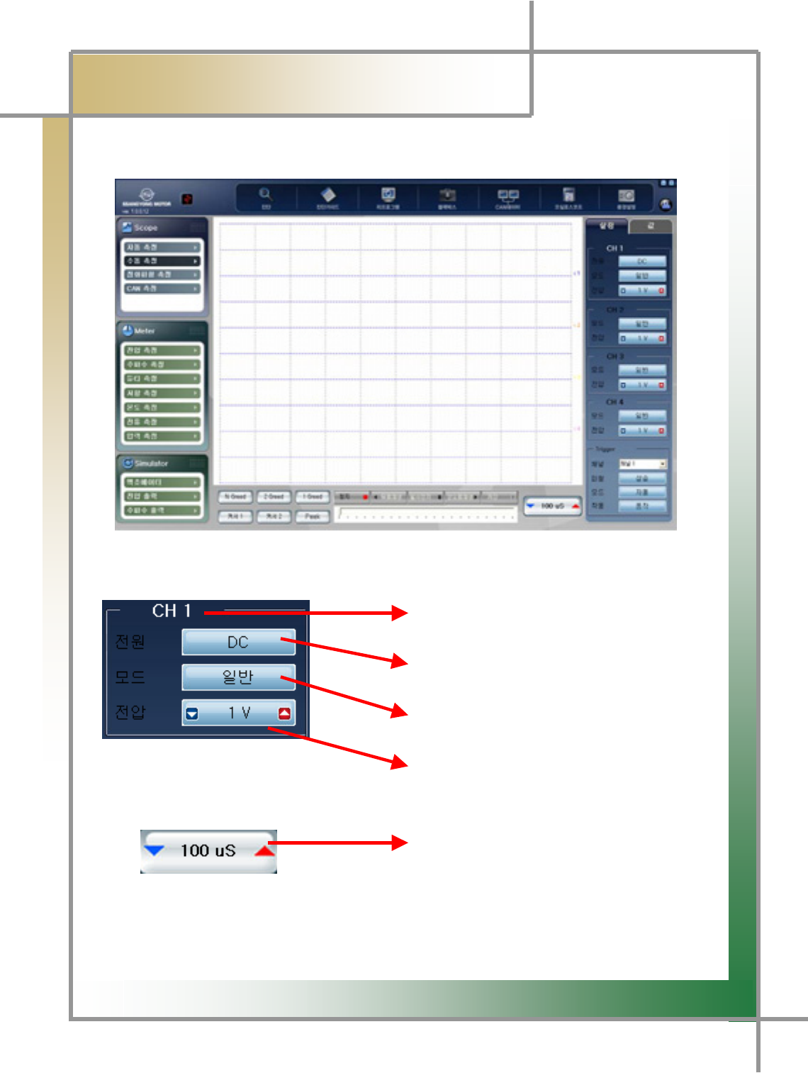
3. Scope (Manual Measurement)
- You can set the voltage and time values at your convenience to measure the wave form.
Figure10.2 Scope_Manual Measurement
Display the scope channel.
Change measurement into AC or DC.
Reverse the wave form by selecting
General/Reverse mode
Measurement Voltage Setting:
To set from 100mV ~ 50V by clicking the left
and right arrows.
Measuring time setting:
To set from 25uS to 10S by clicking the left
and right arrows.
TIPS) In the grid of the screen, horizontal axis indicates time, and vertical axis is
voltage. Voltage and time setting can be interpreted to set the each scale of the
grid
G
G
`^G
GGGGGGGGGGGGGGGGG͑
DSM / MSM User Guide
G
Chapter 10 : Oscilloscopeٻ
G
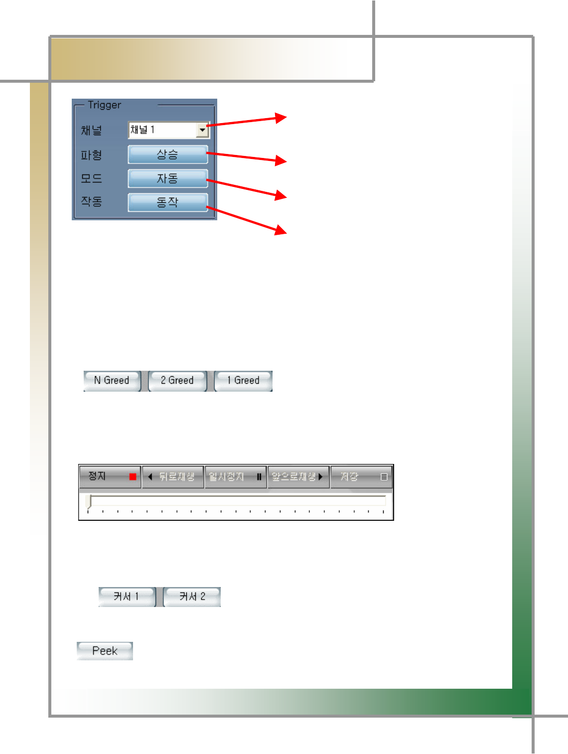
GGGGGGGGGGGGGGGGGGGGGGGGGGGGGGGGGGGGGGGGGGChannel Setting:
Select the channel to which trigger
setting is applied.
Select the standard wave form type to
which trigger setting will be applied.
(increase/decrease)
Select the mode to which the trigger will be
applied.(automatic/normal/single)
Select whether to activate the trigger mode.
TIPS) Trigger setting is a function to display the repetitive or occasional
signals as the good-looking waves in the screen in terms of the setting channel,
voltage level, and screen location.
TIPS) Trigger mode is not activated when the measuring time is configured
more than 100mS.
: Grid Setting Icon
TG You can configure to show the grid from in the screen.
TG N Grid: Default screen setting value to be measured.
TG 2 Grid: Divide the measured screen into 4 divisions.
TG 1 Grid: Divide the measured screen into 1 division.
: Save and Play Wave
Form
Stop the screen, save and analyze the measured wave form.
TG You can view the previously measured wave form based on the time point when to
press the Stop button.
TG It is possible to save it as the file by pressing the Save button
: Create the cross-shaped cursor on
the screen, allowing the user to point to the desired wave from point and analyze
voltage and time.
: You can have more detailed view of the Peek point.
G
G
G
`_G
͑
DSM / MSM User Guide
G
Chapter 10: Oscilloscopeٻ
4. Ignition Wave Form Measurement
- You can check whether there is any malfunction in the vehicle by measuring the ignition
wave form.
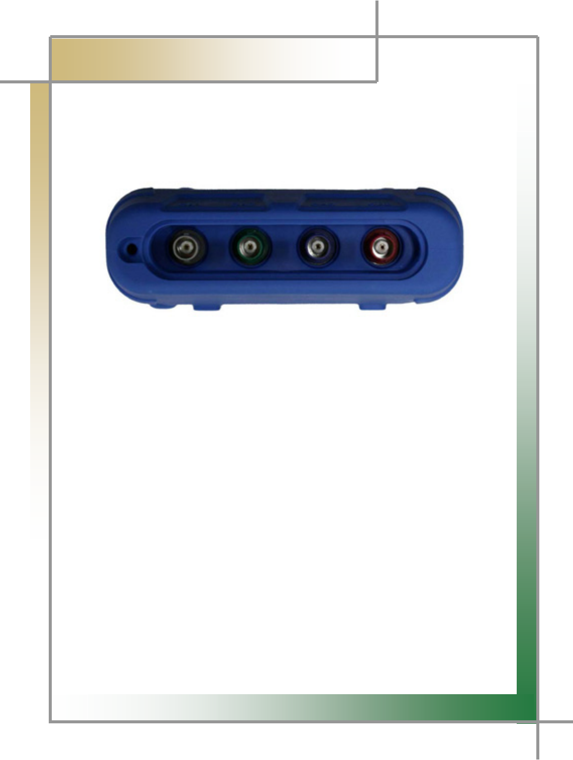
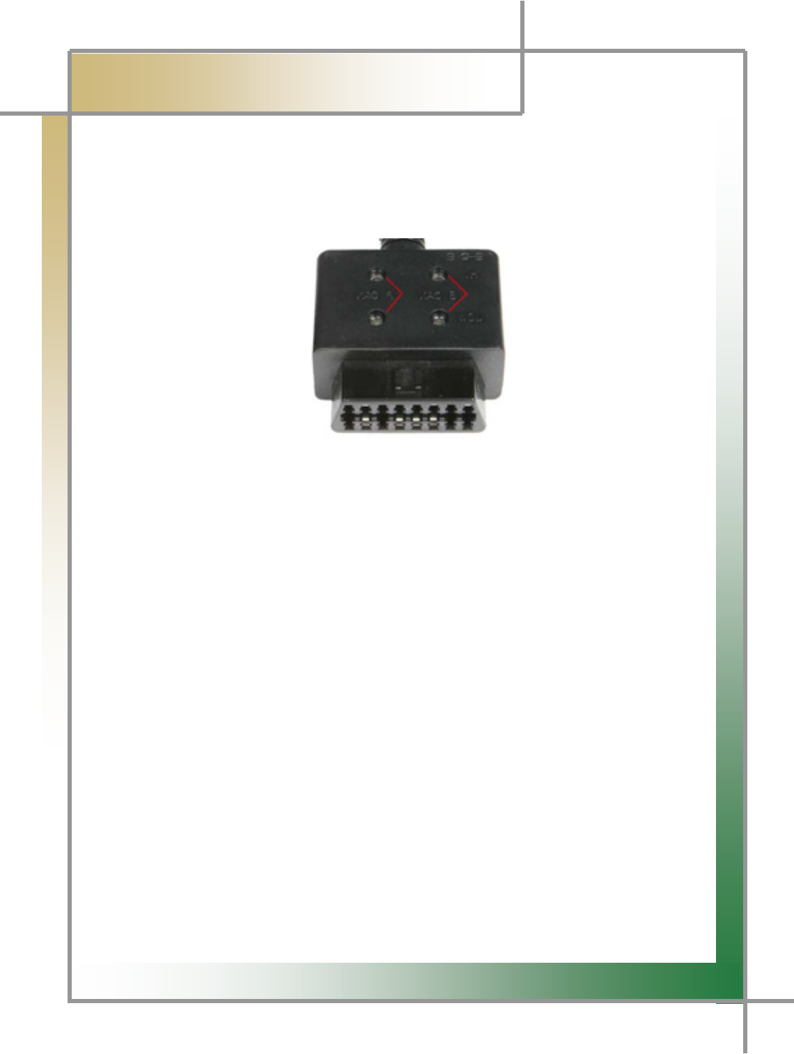
1) Measuring Module Terminal Feature and Default Configurations
Figure10.3 Measuring Module Terminal Feature
It is listed in the order of CH1, CH2, CH3, CH4 from the left as shown in Figure 10.3.
CH1 is the specific one for the resistance measurement.
- Resistance measurement is enabled only through CH1 in the multi-meter function.
CH 2 is the specific one for simulator output.
- Voltage output is available only through CH2.
CH 3 is the specific one for the trigger pickup.
- Trigger pick functions to distinguish the wave form ὤ䋩 by connecting to the
number 1 cylinder
TIPS) Above characteristics are applied when specific functions are used.
When using the scope function, any option selected from channel 1 to 4 enables you
to measure the normal wave forms.
G
G
G
G
G
G
G
``G
͑
DSM / MSM User Guide
G
Chapter 10 : Oscilloscopeٻ
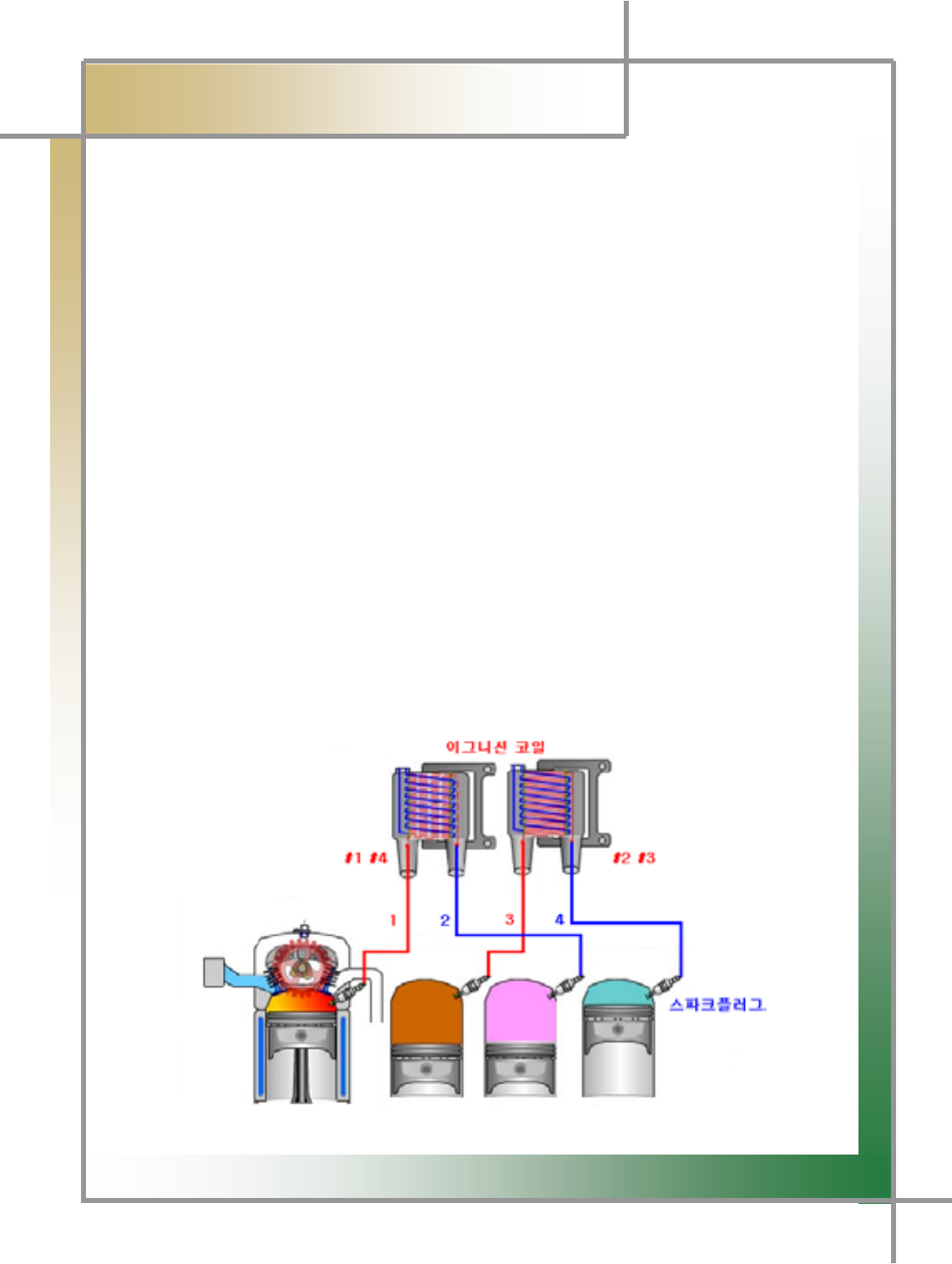
GGGGY) Vehicle Connection (DLI ignition method)
* Ignition Pickup (1~1)
- Connect the 1st ignition pickup linked to the measuring module scope terminal
CH1to the high voltage cable of the cylinder to be measured. (used when measuring
the single wave form)
* Ignition Pickup (1~4)
- Connect the 2nd ignition DLI pickup linked to the measuring module scope terminal
CH1 to the high voltage cable of the cylinder that is number 1 and 3, or number 2
and 4 of the ignition coil. (used when measuring the single wave form)
[Number 1 and 3 High-voltage Cable of Figure 10.4]
- Connect the 2nd ignition DLI pickup linked to the measuring module scope terminal
CH2 to the high voltage cable of the cylinder that is number 2 and 4, or number 1 and
3 of the ignition coil.
[Number 2 and 4 High-voltage Cable of Figure 10.4]
* Trigger Pickup
- To tell the cylinder size, connect to the number 1 cylinder high-voltage cable.
- If the number 1 cylinder in the vehicle to be measured is positive polarity, please
connect it to the high voltage cable in the reverse direction of the spark plug.
[ Number 1 High-voltage Cable of Figure 10.4]
G
G
G
G
G
G
G
G
G
G
G
Figure10.4 DLI Type
G
G
XWW
͑
DSM / MSM User Guide
G
Chapter 10 : Oscilloscopeٻ
G
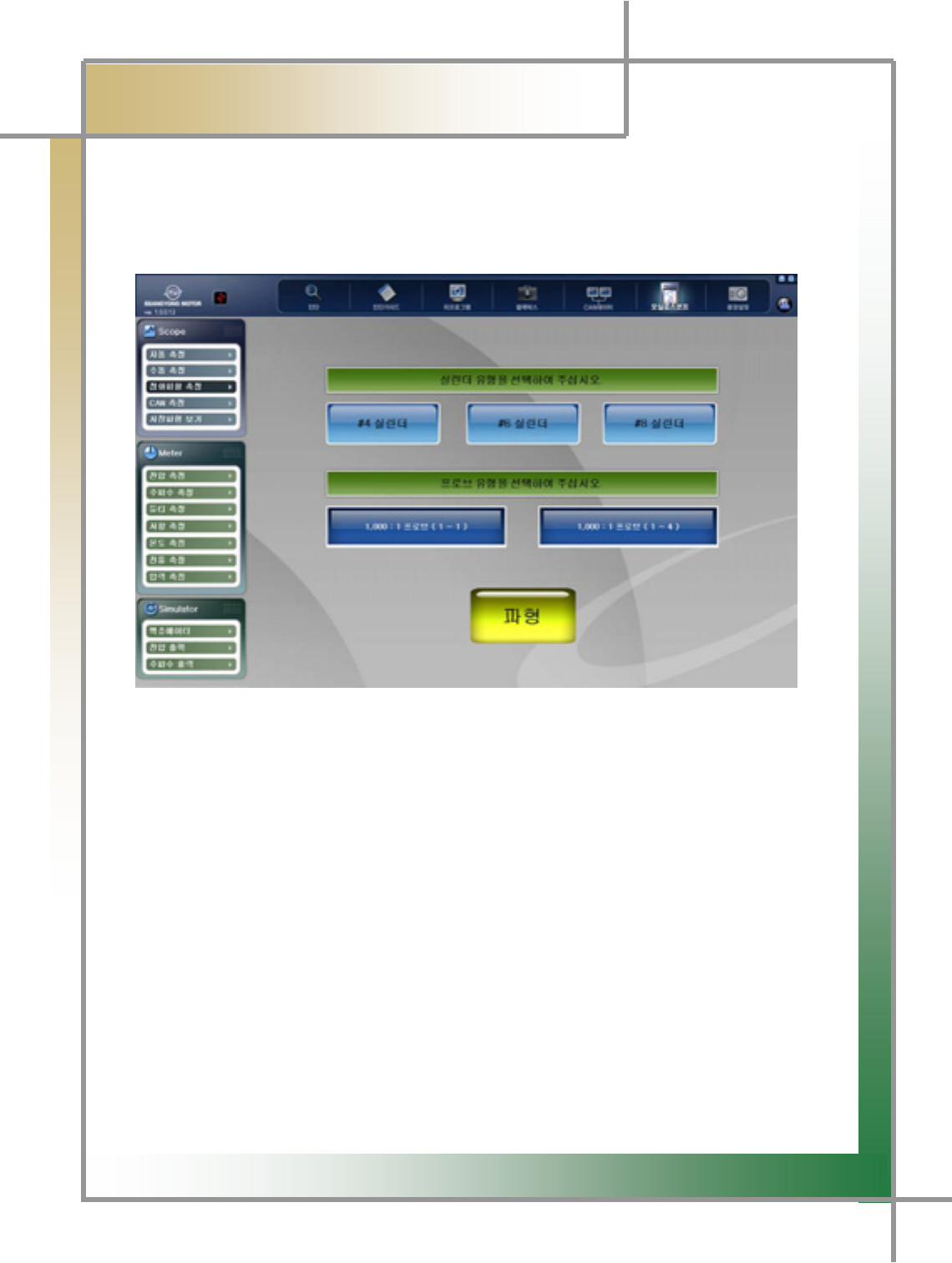
3) Select Menu
- Once the connection to the vehicle and measuring module is complete, select the
measurement menu from the program.
Figure10.5 Ignition Wave Form Measuring Menu
1. Select the cylinder size of the vehicle to be measured.
2. Select the probe type to be measured.
3. If you select the wave form icon, 2nd ignition wave form will be displayed.
G
G
G
G
G
G
G
G
G
XWX
͑
DSM / MSM User Guide
G
Chapter 10 : Oscilloscopeٻ
G
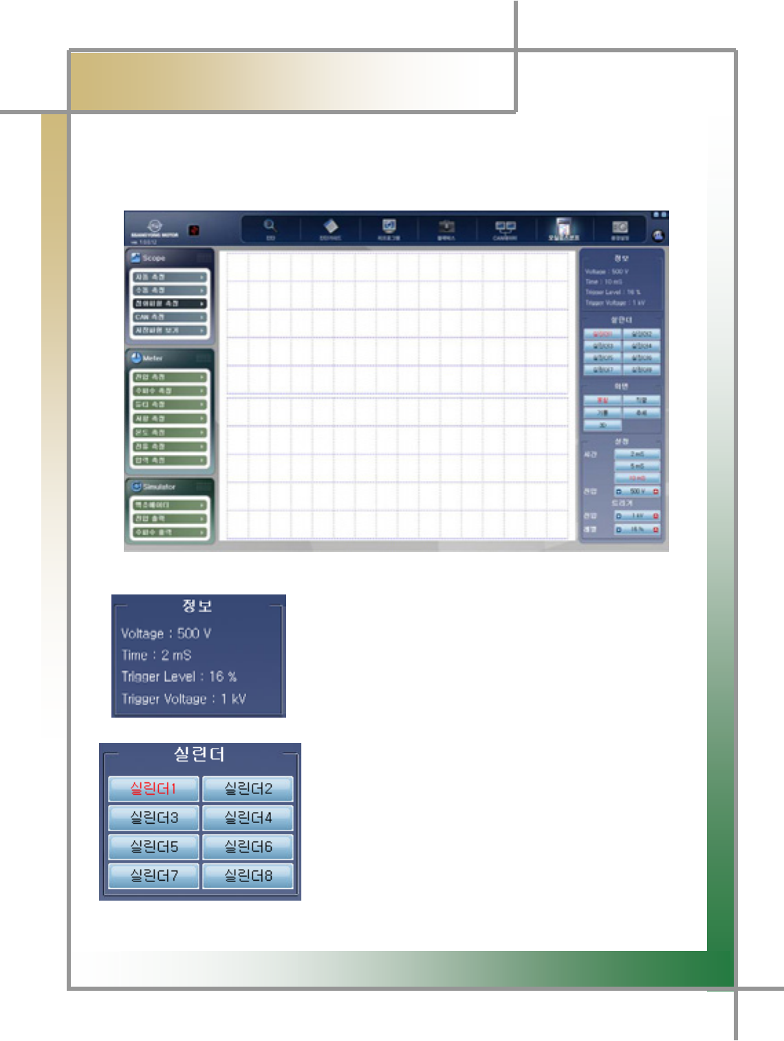
4) Measurement Screen
- Screen where you can check the measurement results.
Figure10.6 Ignition Waveform Measurement Screen
: Window showing the predefined information.
: In the upper screen, the ignition waveform of the entire
cylinder is displayed.
The selecting of the cylinder number, the ignition
waveform of the selected cylinder will be displayed in
the bottom of the screen.
G
G
XWY
͑
DSM / MSM User Guide
G
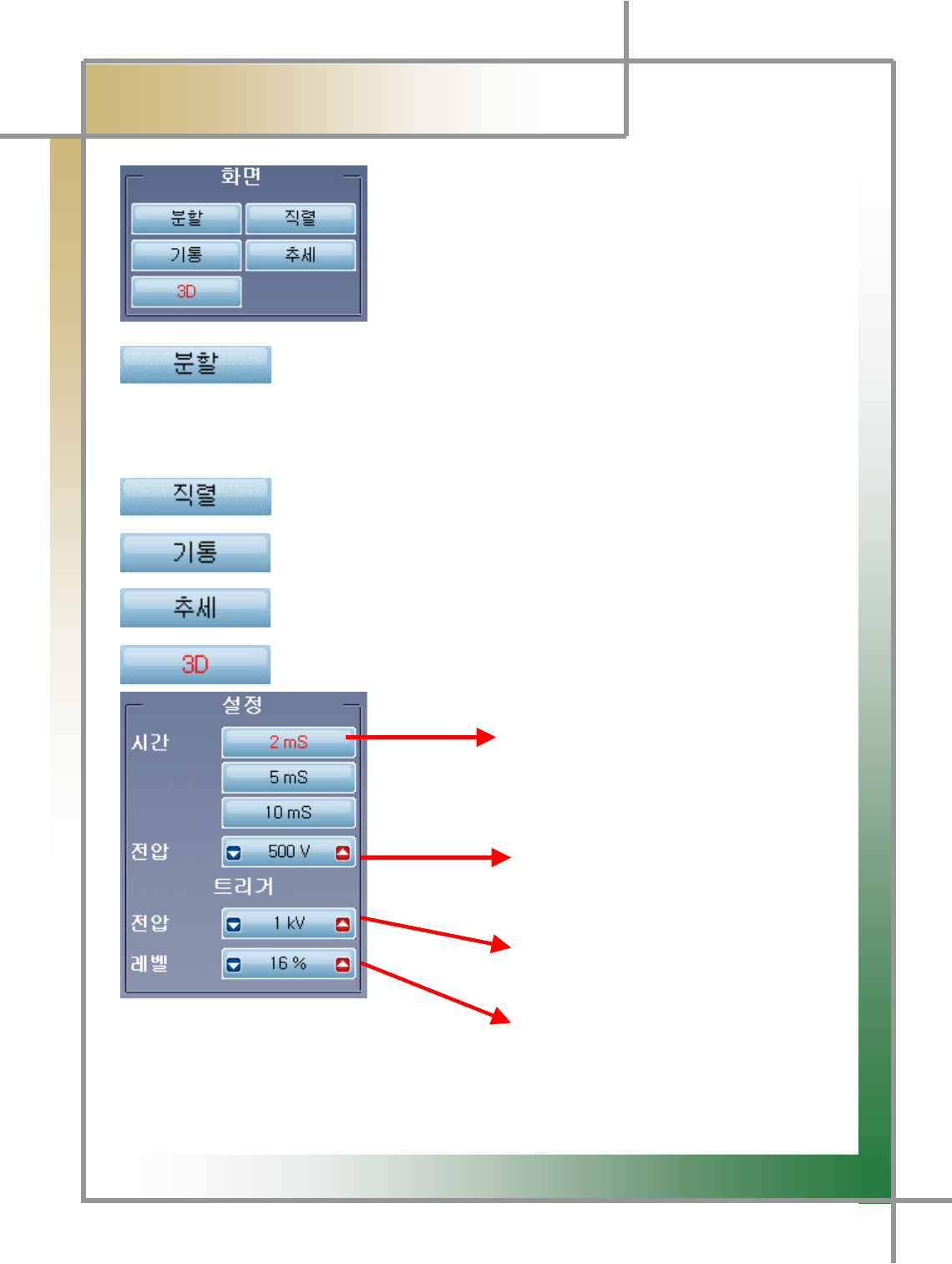
Chapter 10 : Oscilloscopeٻ
G
G
GGGGGGGGGGGGGGGGGGGGGGGGGGGGGGGaGSetting window where you can change the screen
mode.
: Divides the screen into the upper and lower areas; the upper one displays the
waveform of the entire cylinder, and the lower one shows the waveforms by cylinders.
: Displays the entire ignition waveforms in the entire screen.
: Displays the waveform by cylinders.
: Presents the ignition waveform trend graph.
: Presents the ignition waveforms in the 3-dimentional screen.
Allows to set the time axis.
Allows to set the voltage axis using the
Right/left arrows (100V ~50Kv)
Allows to set the trigger voltage using
The right/left arrows. (100V ~50Kv)
A
llows to set the trigger level using the
left/right arrows.
G
G
XWZ
͑
DSM / MSM User Guide
G
Chapter 10: Oscilloscope
5. CAN Waveform Measurement
- You can measure the CAN waveform by connecting the scope cable to CAN connecto
r
that is equipped in the W200 vehicle.
Figure10.7 W200 CAN 㙸䉤
1) How to Measure
1. Connect the W200 CAN adapter to the CAN diagnosing connector of the vehicle.
Connect the measuring module and scope cable, and link the measurement point to
the scope probe.
2. Enter into the oscilloscope mode.
3. Select the CAN measurement mode.
G
G
G
XW[
͑
DSM / MSM User Guide
G
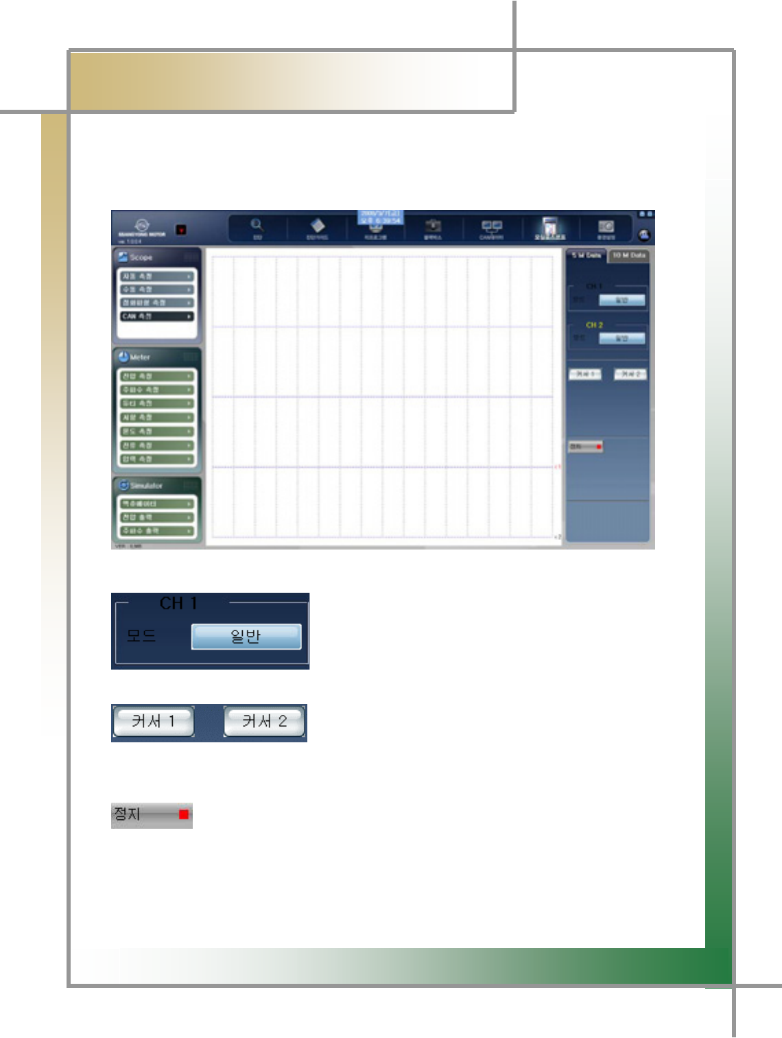
Chapter 10: Oscilloscope
G
GGGG2) Menu Description
- Provides information about the CAN data measurement menu.
Figure10.8 CAN Measurement Menu
M : Function to convert the waveform to the general
mode or reverse mode by channels.
: Creates the cross-
shaped cursor, allowing the user to point to the desired
waveform point, and analyze the data.
: Function to stop the screen for the precise analysis of the waveform.
G
G
XW\
͑
DSM / MSM User Guide
G
Chapter 10: Oscilloscope
G
G
G
G
G
G
G
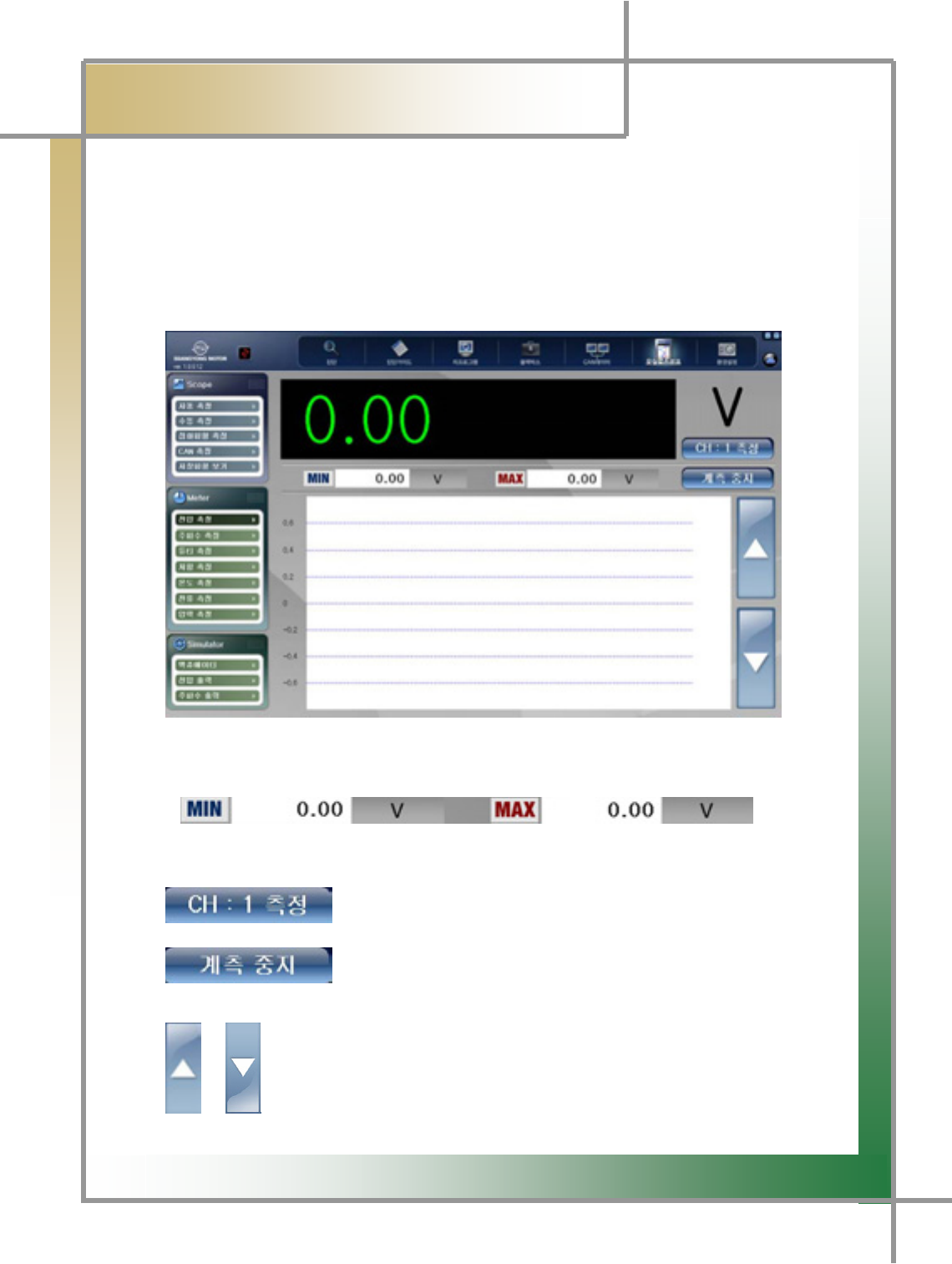
6. Meter Function
- You can realize the general multi-meter functions, and even in the condition without PC
connection, you can independently implement the multi-meter functions by the
measurement module.
- Additional pickup(option) is needed when measuring the temperature, pressure,
current.
Figure10.9 Meter function_voltage measurement
: You can compare the minimum measurement value and maximum value.
: You can select the measurement channel.
: You can stop the measurement.
/ : You can view the different default values by the measurement items.
G
G
XW]
͑
DSM / MSM User Guide
G
Chapter 10: Oscilloscope
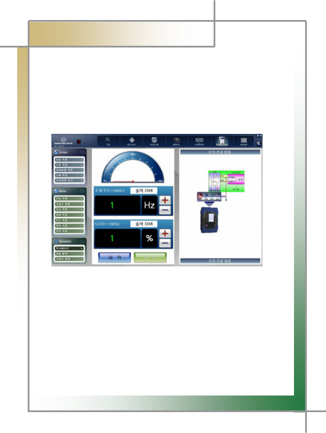
7. Simulator
- It provides a function to prepare operation condition randomly only for the actuators
and sensors activated by frequency, duty, and voltage, and check whether it is operated o
r
not.
1) Actuator
- You can adjust the frequency and duty to randomly operate actuators with earth
control from ECU.
Usage example) ISC valve, injector etc.
Figure10.10 Simulator_Actuator
1. Connect the vehicle and measuring module as shown in the right side of the
screen.
2. Adjust the appropriate frequency and duty, and click the Start icon.
3. Verify whether the actuator is in action or not.
TIPS) When using the simulator function, be sure to connect the scope channel as
directed by the screen. If the connection is not correctly connected, the function
cannot be realized.
G
G
XW^
͑
DSM / MSM User Guide
G
Chapter 10: Oscilloscope
G
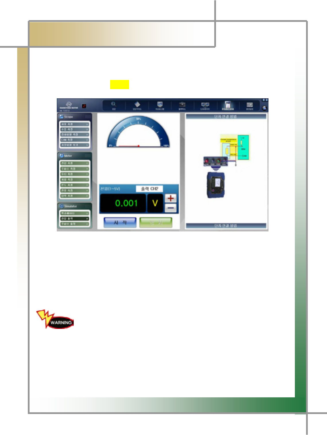
2) Voltage Output
- It allows you to measure the items controlled with voltage from ECU.
Usage Example) ㏘⦐䏴 position sensor, cooling water temperature sensor etc.
Figure10.11 Simulator_Voltage Output
1. Connect the vehicle and the measuring module as shown in the right side of the
screen.
2. Adjust and set to the proper voltage, and click the Start icon.
3. Verify whether the vehicle status is changed or not.
When performing the simulation test, be sure to check the vehicle
status and continue the process. Excessively intensive
test may cause the damage in the equipment and the vehicle.
G
G
G
G
G
G
XW_
͑
DSM / MSM User Guide
G
Chapter 10: Oscilloscope
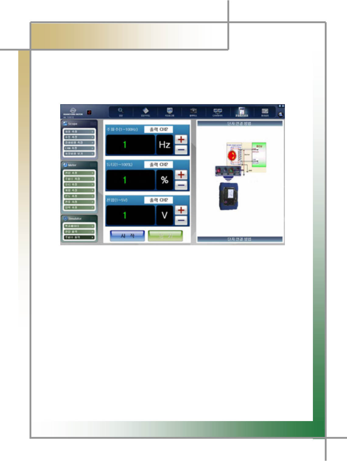
3) Frequency Output
TG It allows you to measure the items controlled with frequency from ECU.
Usage example) crank angle sensor etc.
Figure10.12 Simulator_frequency output
1. Connect the vehicle and the measuring module as shown in the right side of the
screen.
2. Adjust voltage and set to the proper voltage, and click the Start icon.
3. Verify whether the vehicle status is changed or not.
G
G
G
XW`
͑
DSM / MSM User Guide
G
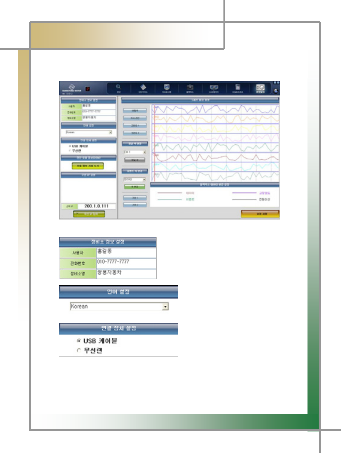
Chapter 11: Configuration
G
TG Function to set the product usage configuration.
Figure10.13 Configuration
: To set the business information.
: To change the displayed language.
(KOREAN / ENGLISH)
: To select the way of connecting to the
diagnosis module.
TIPS) Measuring module is available only with the USB cable.
G
G
XXW
͑
DSM / MSM User Guide
G
Chapter 11: Configuration
G
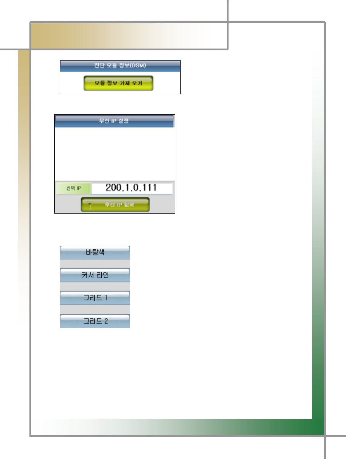
GGGGGGGGGGGGGGGGGGGGGGGGGGGGGGGGGGGGGGGGGGGGGaG~GGGGG G
G
GGGGGGGGGGGGGGGGGGGGGGGGGGGGGGGGGG
GGGUSB cable, you can verity the information of the diagnosis module.
: With Connection Device set to
Wireless LAN, if you click Search
Wireless, the searched IP address will
be displayed.
If you select the IP of diagnosis
module, the selected IP address will be
displaced in the below window.
.
TIPS) For detailed description of the wireless setting, please refer to Chapter 2.
: : Set the background color of the service data graph mode.
: Set the color of cursor line.
: Set the color of horizontal dotted line.
: Set the color of vertical dotted line.
TIPS) When viewing the service data of the vehicle diagnosis function with
graph presentation, the increase in the item number can cause difficulty in analyzing
the data due to the redundant background colors and line colors. In this case, you
can change the color for your convenience.
TIPS) To exit from Configuration, be sure to click the Save icon and store the
changed information.
G
G
G
XXX
͑
DSM / MSM User Guide
G
Chapter 11 : Configuration
G
G
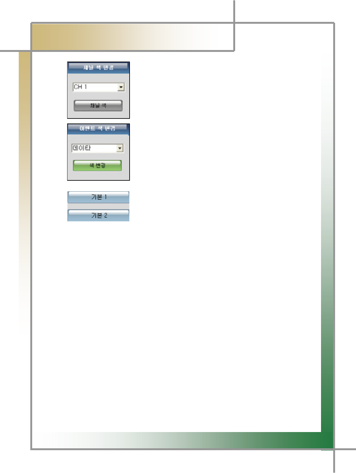
GGGGGGGGGGGGGGGGGGGGGGGGGGGG: Configure the color by channels.
: You can change the event color in the black box function.
: It automatically changes the screen color into the
predefined default value.
G
G
G
G
G
G
G
XXY
͑
DSM / MSM User Guide
G
ڬېڼۇۄۏ۔ٻڲڼۍۍڼۉۏ۔ٻ
x
G
~
G
m
G
wGuG G
tGuG G kGGtG G
~GwG ~GGGGGGG kGGwG G
jG hG G {G G G
zGhG hG G {G G G
G
x u’GGGGGGGGGGGGGtvzmUG G
x pGGSGGGtGGGGGGGGGGGGGGUG
x pG G G G G G G G G G SG G G G G G G G G
GGGjGGG¡GGUG
x ~GGGGGSGGGGGGGUG G
G
jGsGjGjG G
G
XUG ~GGGGG G
GGG
GGGGGGGGGGGGGGGtG{G
GGGGGGGGGGGGGGGGG
GGGGGGGGGGGGGGGGjGjG
~GGSG G yGGG
~G XWG G G
G
wGGGGGGGUG
~G XG G G
G
wGG
~G G G G
G OSG G G G G
G G G G SG
G G G G G
PG ~G XG G G
G
mGGGGG
wGG wGGGGGGGG~G G G G G G G
GGG G tG G G
G ’G
G G
G
wGGGGGGGG G
kGGGGGGGG wGG
G
x {GGGGGGGGGGGGGGGGUG
G
YUG hGxG~GwG
GG
kG{G jGjG
~GGSG G jGyG G
~GGGGGGGGG yG G G G G G G G G XWLG
OGaGGPG
~G G G SG G G G G G G G
GGGGGUG
G
G
ZUG {GGGGGGGGGGSGGGGGUG
G
XPG kG G G G G G G G G G G G G G OG G SG
GGPG
YPG kGGGGGGGG¡GSGGGGGG
GGGSGSGGUG G
ZPG kGGGGGG
[PG kGGGGGGGG
\PG ~GGGGGGGaGGOGUPG
]PG wGGGGGGGG
^PG tGGGGGSGGSGGUG
_PG kGGGGGG¡GGG G
`PG ~GGGGGG“j”GGGG|GnUG
G
uG
lujG}GkG{GZTSGXZGmsG
X`^TZZGnTSGnTSGzSGyGGrGX\YTW\WG
G
jGzaGW_WT`WWT`ZZZGGGGGaVVUTUG
X\__T_][YOhVzPG

G
G
XXZ
͑
DSM / MSM ㌂㣿㧦 Ṗ㧊✲
G
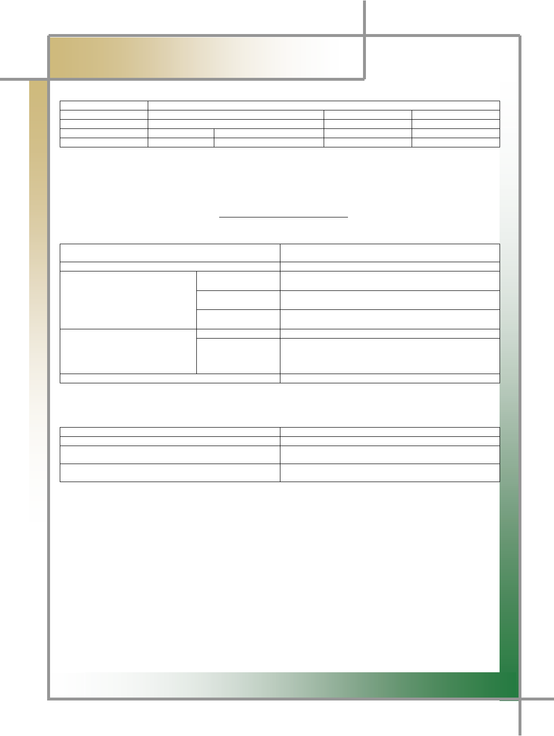
ٻInformation Communication Device
Certification InformationG
G
zModel Name : DSM
zDevice Name: Diagnosis System Module
zBusiness Name of the Certified: Nextech co., Ltd
zManufacturer/Country: Nextech co., Ltd / Republic of Korea
zCertificate No. : NEX-SSYMซDSM(A)
zDate Certified: 2008
z
zModel Name : MSM
zDevice Name: Measuring System Module
zBusiness Name of the Certified: Nextech co., Ltd
zManufacturer/Country: Nextech co., Ltd / Republic of Korea
zCertificate No. : NEX-SSY-MSM(A)
zDate Certified: Feb., 26, 2008
G
G
G
G
G
G
Wireless Compact Flash Adapter Version: 1.0
Page 16 of 17
Appendix B – Regulatory Compliance
Information
Radio Frequency Interference Requirements
This device complies with Part 15 of FCC Rules and Canada RSS-210. Operation is subject to the
following conditions:
1. This device may not cause harmful interference.
2. This device must accept any interference received, including interference that may cause
undesired operation.
3. To comply with RF safety requirements, you must maintain a distance of 20 cm from the antenna
when operating the device.
4. This transmitter must not be co-located or operating in conjunction with any other antenna or
transmitter.
Interference Statement
This equipment has been tested and found to comply with the limits for a Class B digital device,
pursuant to Part 15 of the FCC Rules; These limits are designed to provide reasonable protection
against harmful interference in a residential installation. This equipment generates, uses and can
radiate radio frequency energy and, if not installed and used in accordance with the instructions, may
cause harmful interference to radio communications. However, there is no guarantee that interference
will not occur in a particular installation. If this equipment does cause harmful interference to radio or
television reception, which can be determined by turning the equipment off and on, the user is
encouraged to try to correct the interference by one of the following measures:
1. Reorient or relocate the receiving antenna.
2. Increase the separation between the equipment and receiver.
3. Connect the equipment into an outlet on a circuit different from that to which the receiver is
connected.
4. Consult the dealer or an experienced radio/TV technician for help.
FCC Caution: To assure continued compliance, (example – use only shielded interface cables when
connecting to computer or peripheral devices). Any changes or modifications not expressly approved by
the party responsible for compliance could void the user’s authority to operate this equipment.
This device complies with Part 15 of the FCC Rules. Operation is subject to the following two
conditions: (1) This device may not cause harmful interference, and (2) this device must accept any
interference received, including interference that may cause undesired operation
IMPORTANT NOTE:
FCC RF Radiation Exposure Statement:
This equipment complies with FCC RF radiation exposure limits set forth for an uncontrolled environment.
This equipment should be installed and operated with a minimum distance of 20 centimeters between the
radiator and your body.This transmitter must not be co-located or operating in conjunction with any other
antenna or transmitter.
IMPORTANT Safety Instruction:

Wireless Compact Flash Adapter Version: 1.0
Page 17 of 17
1) Read these instructions.
2) Keep these instructions.
3) Heed all warnings.
4) Follow all instructions.
5) Do not use this equipment near water.
6) Do not using near any heat sources such as radiators, heat resisters, stove, or other equipment that
produce heat.
7) Internal Lithium coin batteries type:
- Rechargeable coin battery(BT2) SANYO ENERGY, ML 2430
- RTC(Real Time Clock) coin battery(BT1) FDK Energy Co., Ltd., CR 2032
G
European Union Regulatory Notice
Compliance with these directives implies conformity to harmonized European standards (European Norms)
that are listed in the EU Declaration of Conformity issued by HP for this product or product family. This
compliance is indicated by the following conformity marking placed on the product.
The wireless telecommunications functionality of this product may be used in the following EU and
EFTA countries:
Austria, Belgium, Bulgaria, Cyprus, Czech Republic, Denmark, Estonia, Finland, France, Germany, Greece,
Hungary, Iceland, Ireland, Italy, Latvia, Liechtenstein, Lithuania, Luxembourg, Malta, Netherlands, Norway,
Poland, Portugal, Slovak Republic, Slovenia, Spain, Sweden, Switzerland, and United Kingdom.
Products with 2.4-GHz wireless LAN devices France
For 2.4 GHz Wireless LAN operation of this product certain restrictions apply:
This product may be used indoor for the entire 2400-2483.5 MHz frequency band (channels 1-13). For
outdoor use, only 2400-2454 MHz frequency band (channels 1-9) may be used. For the latest requirements,
see http://www.art-telecom.fr.
Italy :
License required for use. Verify with your dealer or directly withthe General Direction for Frequency Planning
and Management (Direzione Generale Pianificazione e Gestione Frequenze).
CE RF Radiation Exposure Statement:
Caution This equipment complies with European RF radiation exposure limits set forth for an uncontrolled
environment. This equipment should be installed and operated with a minimum distance of 20 centimeters
between the radiator and your body.This transmitter must not be co-located or operating in conjunction with
any other antenna or transmitter.

Type of equipment: Automotive Scanner
Brand Name /Trade Mark: Diagnostic System Module
Type designation /model: DSM
Manufacturer: Nextech Co., Ltd.
In accordance with the following Directives:
Directive 1999/5/EC Radio Equipment and Telecommunications Terminal Equipment and the
mutual recognition of their conformity
Including amendments by the CE Marking Directive 1999/5/EC
The following harmonized European standards or technical specifications have been applied:
Art.3.1.a) EN 60950-1: 2001 + A11:2004
EN 50371 (2002)
Art.3.1.b) ETSI EN 301 489-1 V1.6.1 (2005-09)
ETSI EN 301 489-17 V1.2.1 (2002-04)
Art.3.2) ETSI EN 300 328 V1.7.1 (2006-10)
Test report issued by:
RF: CTK Co., Ltd.
LVD: CTK Co., Ltd.
EMC: CTK Co., Ltd.
The CE Marking on the products and/or their packaging signifies that Nextech Co., Ltd. hold the
reference technical file available to the European Union authorities.
Place and date of issue: E&C Venture Dream Tower the 3rd ,13th Floor, 197-33,
Guro-Dong, Guro-Gu, Seoul, Korea / SEPTEMBER 02, 2008
[Place, date]
EU
SEPTEMBER 02, 2008
[Name and signature of person responsible]
Young-Hak Kwon /assistant manager