NEXTECH NT-TPMS100 TPMS MODULE User Manual EMISSION TEST REPORT
NEXTECH CO., LTD. TPMS MODULE EMISSION TEST REPORT
UserManual.wiki
>
NEXTECH
>
NT TPMS100 User Manual
Users Manual
Navigation menu
Upload a User Manual
Namespaces
Wiki Guide
HTML
PDF
Info
Views
User Manual
Discussion / Help
Navigation
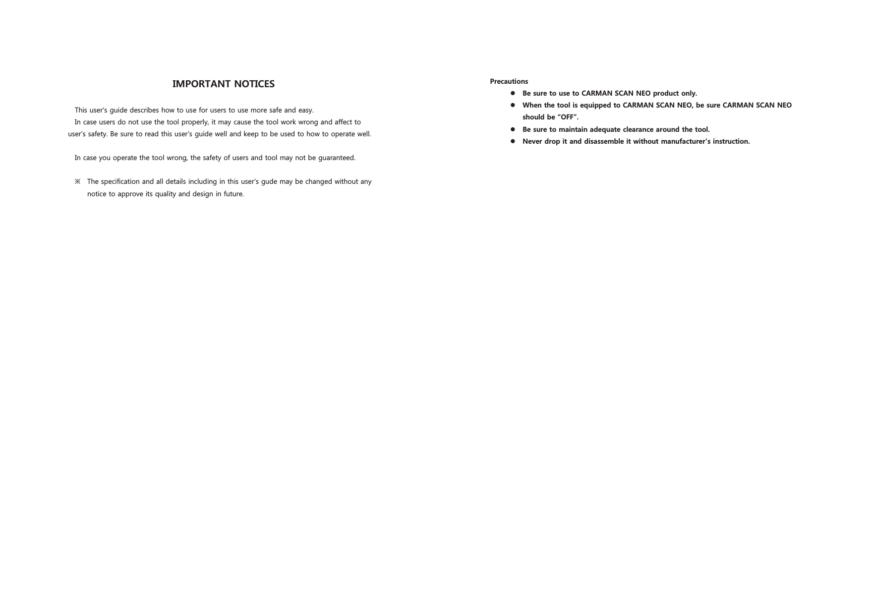
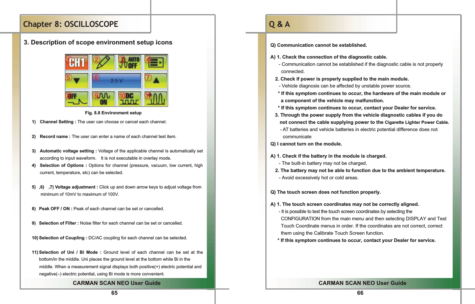
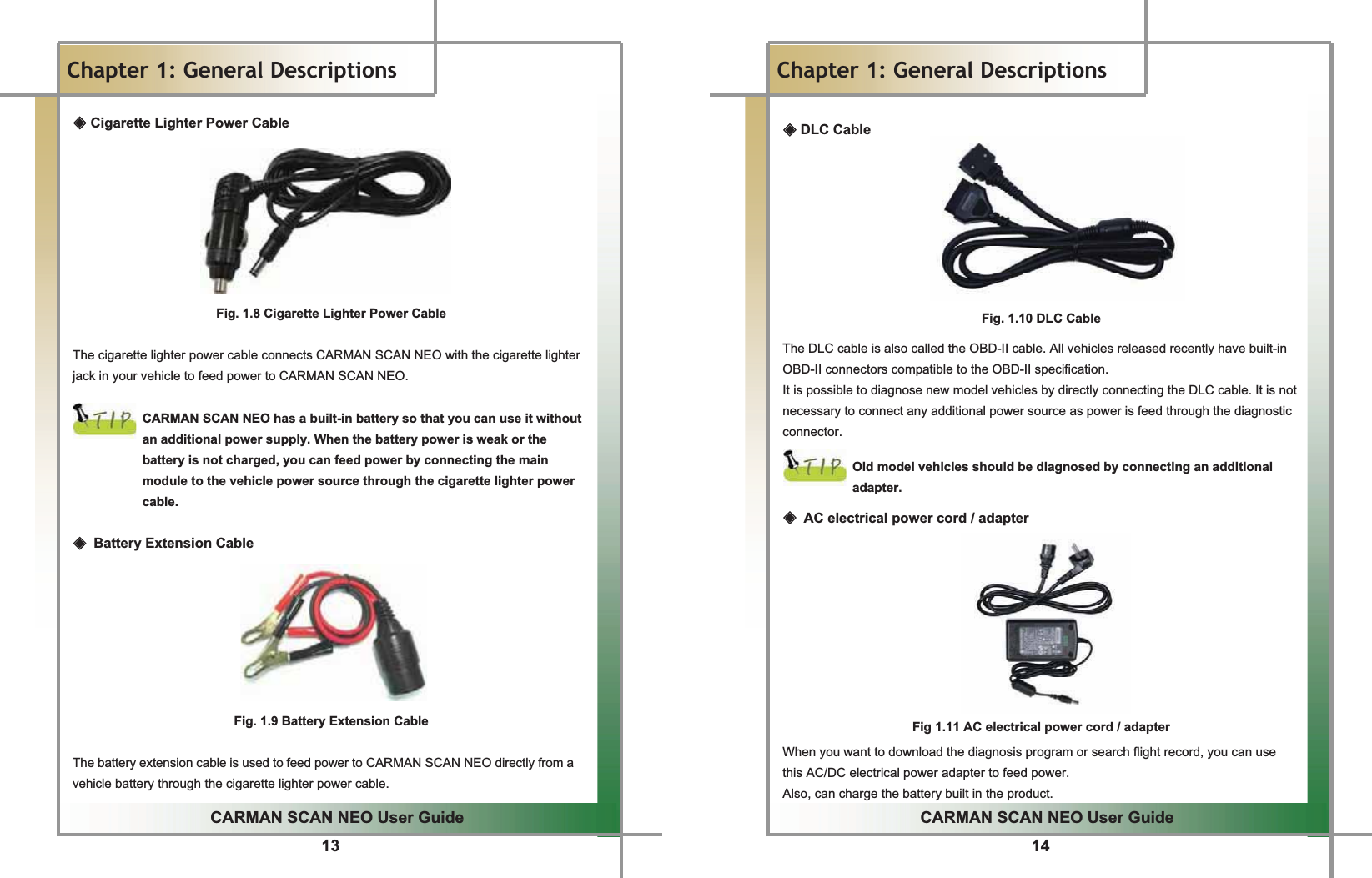
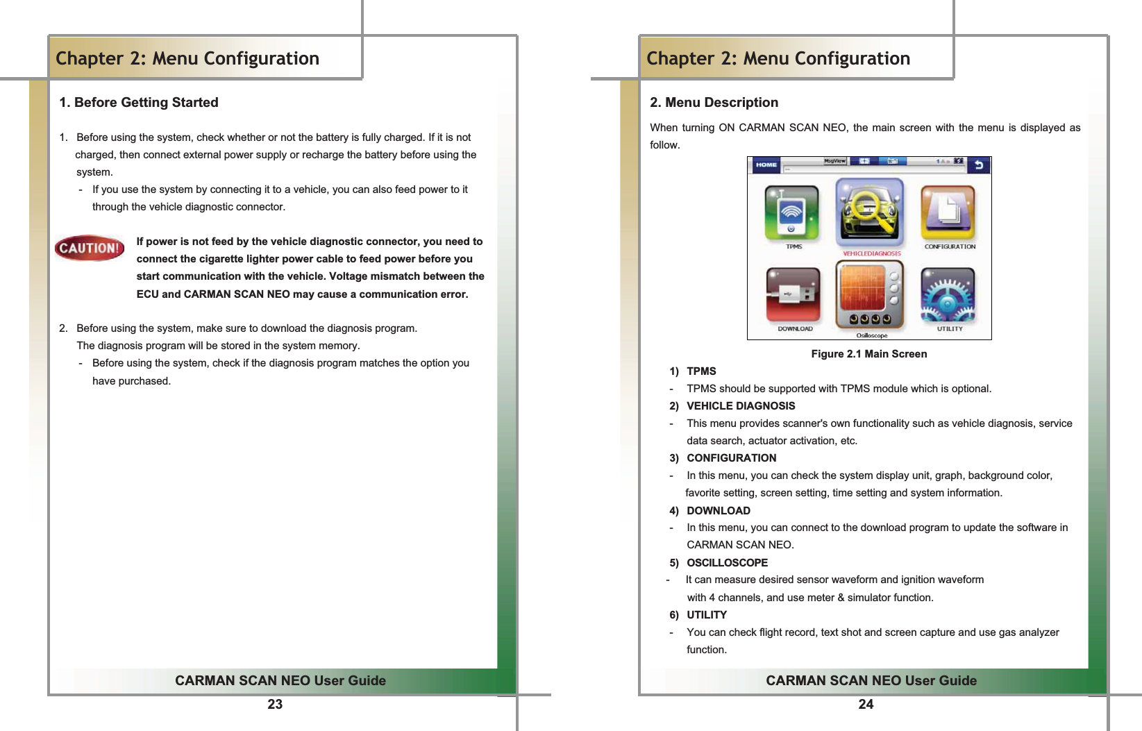
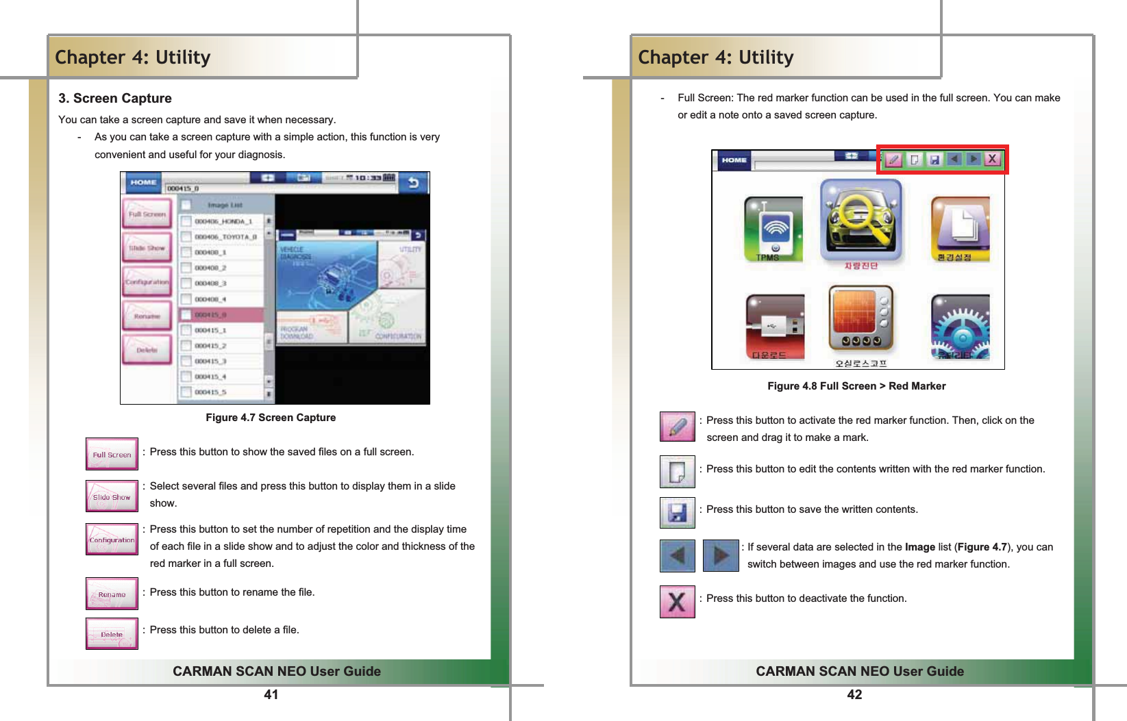
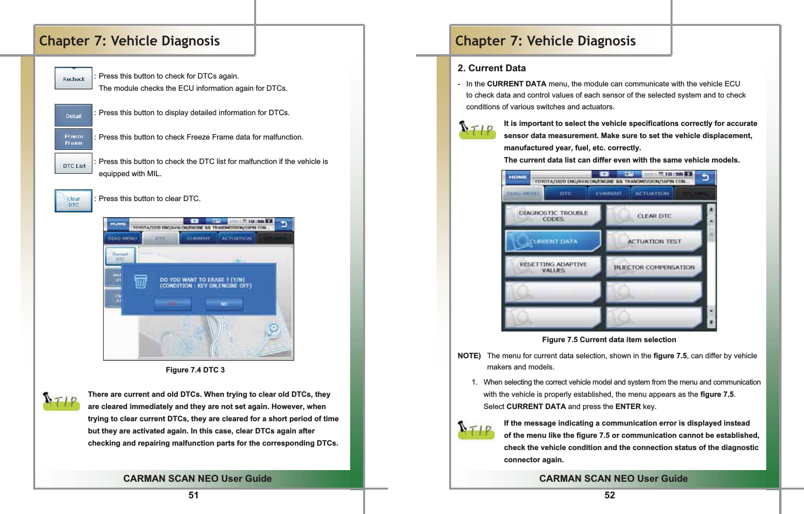
![ %QORQPGPVCPF5RGEKHKECVKQP%QORQPGPV2KE62/5/1&7.'/CKP7PKV5RGEKHKECVKQP+VGO 5RGEKHKECVKQP%27 670)$50ELW&RUWH[0&38/GOQT[ .E\WH)/$6+0(025<4(4'%'+8'40+]$6.)6.0+]$6.)6..(64#05/+66'4 .+]1RGTCVKPI6GORGTCVWTG &a&1RGTCVKPI8QNVCIG '&9ROWa9ROW5+<' PP[PP[PP +PUVCNNCVKQP%HVXUHWRRII&$50$16&$11(2EHIRUH\RXLQVWDOO730602'8/(,QVWDOO7306PRGXOHWRWKHGLUHFWLRQDVEHORZ7KHODEHOę7306ĚVKRXOGEHXSSHUSRVLWLRQDVEHORZDQGLWPD\QRWEHLQVWDOOHGLIWKHGLUHFWLRQLVRSSRVLWH$ERYHPDUNHGDUHDLVWKHVSDFHWRLQVWDOO7306PRGXOHDQGWKHFDSVKRXOGEHRSHQHGWRࡢ ̐սLQVWDOO730602'8/(](https://usermanual.wiki/NEXTECH/NT-TPMS100/User-Guide-1451426-Page-4.png)
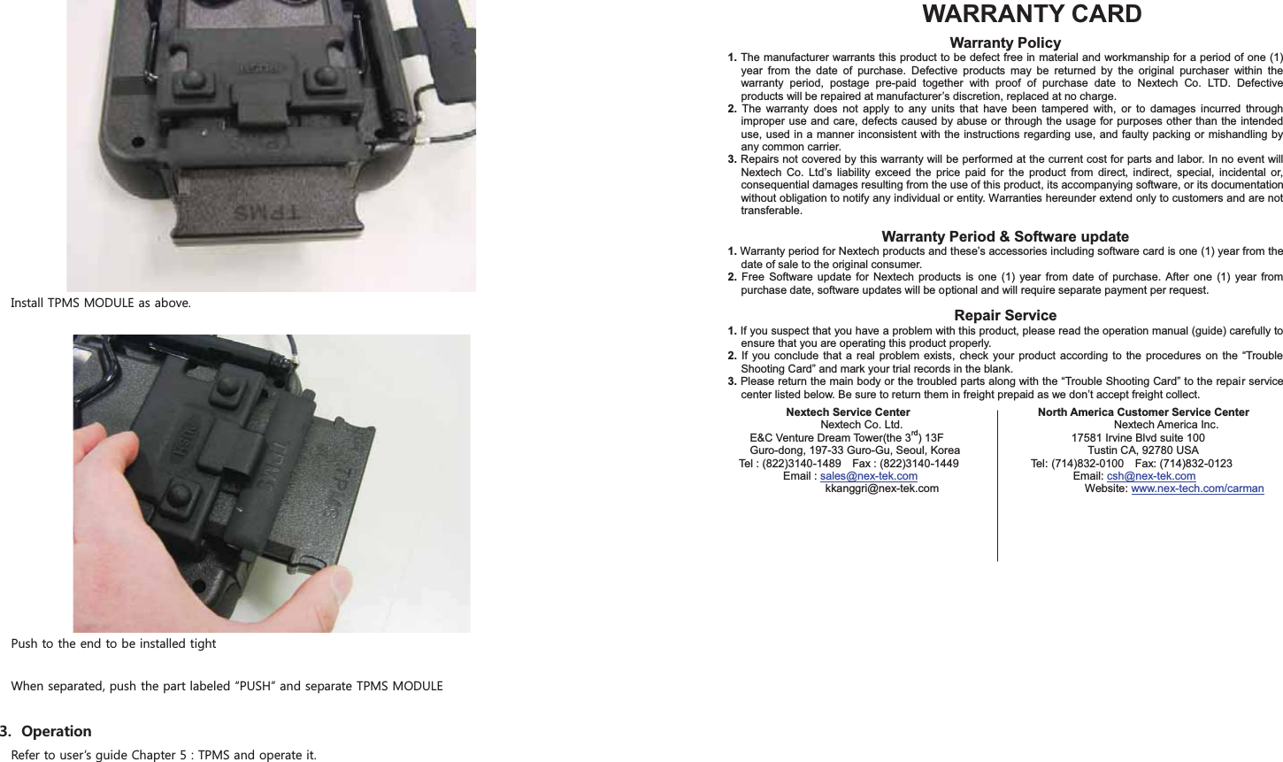
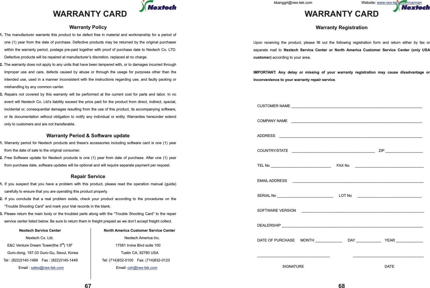
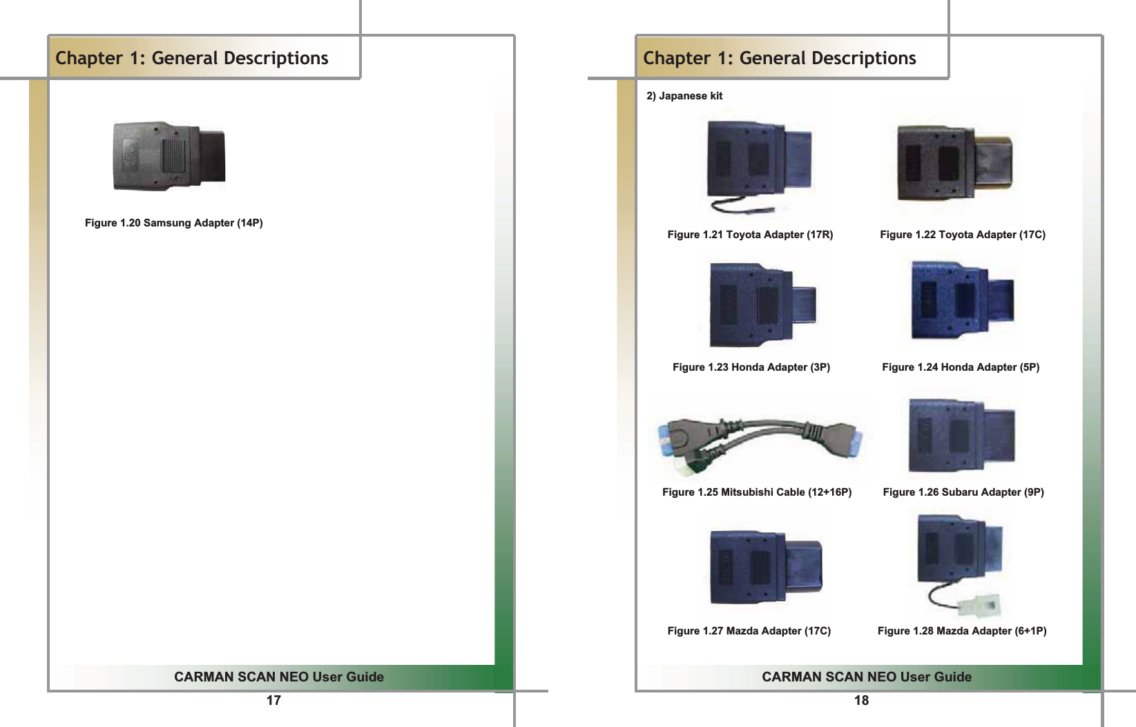
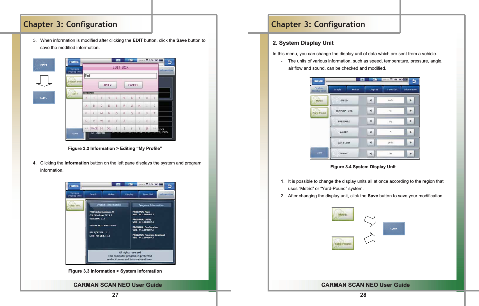
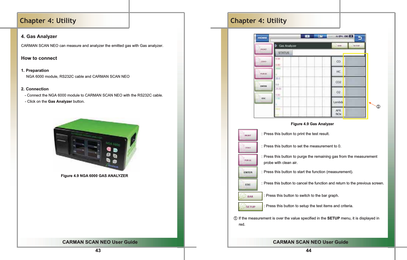
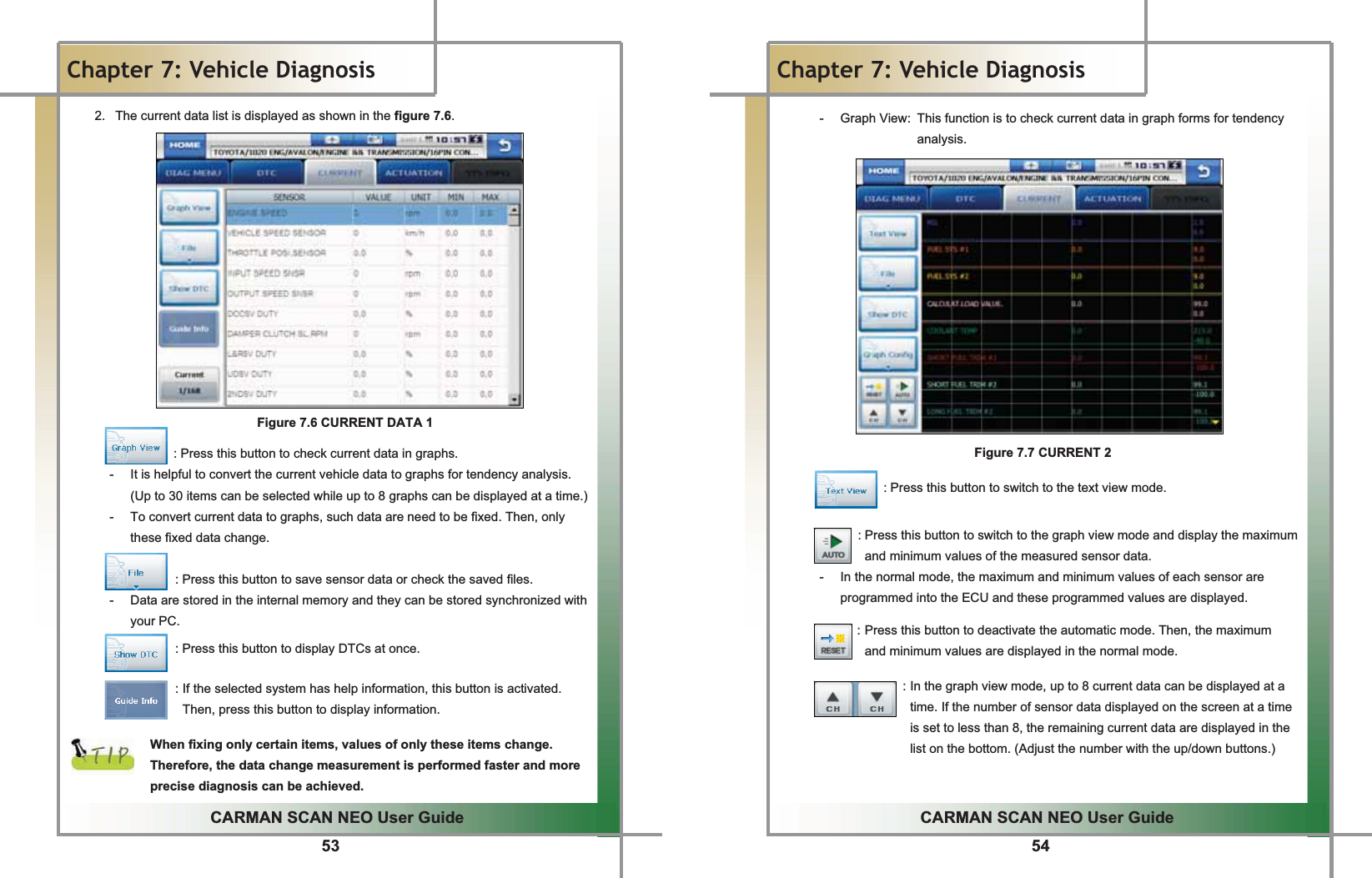
![5GGCARMAN SCAN NEO User GuideGGChapter 1: General Descriptions 1. Product Features CARMAN SCAN NEO can check vehicle ECU information and malfunction status through the OBD-I, OBD-II and CAN communication. You can connect CARMAN SCAN NEO to the vehicle diagnostic connector with a diagnosis cable to check if any of the engine, automatic transmission, ABS, air bag, power steering and other devices has an error, view current data and use actuator drive features. CARMAN SCAN NEO has the following features: ඖ Diagnoses Korean, Japanese and European vehicles. - OBD-I , OBD-II, MOBD(ISO 9141-2, SAE-J1850, KWP-2000, CAN, SAE J1587) ඖ Supports vehicle troubleshooting and current data search. - You can diagnose vehicles with their sensors and switches, and save and reload the current data. ඖ Supports automatic actuator inspection. - This function runs/stops the actuator and switches forcibly in order to check if the corresponding active device is normal. ඖ You can save data and upgrade the diagnosis program by connecting the product to your PC. ඖ You can change the sound effects and display unit of the CARMAN SCAN NEO. ඖ Provides the LCD brightness adjustment function. ඖ With the built-in battery, you can perform diagnosis without an additional power supply. (for vehicles without DLC power) G6GGCARMAN SCAN NEO User GuideGGChapter 1: General Descriptions2. Product Specifications GItem Detail Specifications CPU PXA-320 806MHz O.S Window CE 5.0 LCD 5.7 inch (Color / Touch Screen) Connectivity USB (USB 2.0 / Compliant) Operating Temperature -10 ~ 60 Operating Voltage 8 ~ 32V Function TPMS / VIDEO(Composite) / Input(PAL,NTSC) User Interface Touch Screen & Multi Keyboard ProtocolKWP 2000, ISO 9141-2, J1850(VPW,PWM) Dual Wire CAN(2.0A, 2.0B) J1587, Single Wire CAN, Hi Speed Serial Maximum Sample Rate 25[MHz/S] per Channel Volt / division 10m[V] to 100[V] in a 1, 2.5, 5 Sequence Scope Time Setting 1[༕] ~ 10[S] Input Impedance 1[M] Battery Li-Polymer 7.4[V] 4200[mA] G](https://usermanual.wiki/NEXTECH/NT-TPMS100/User-Guide-1451426-Page-9.png)
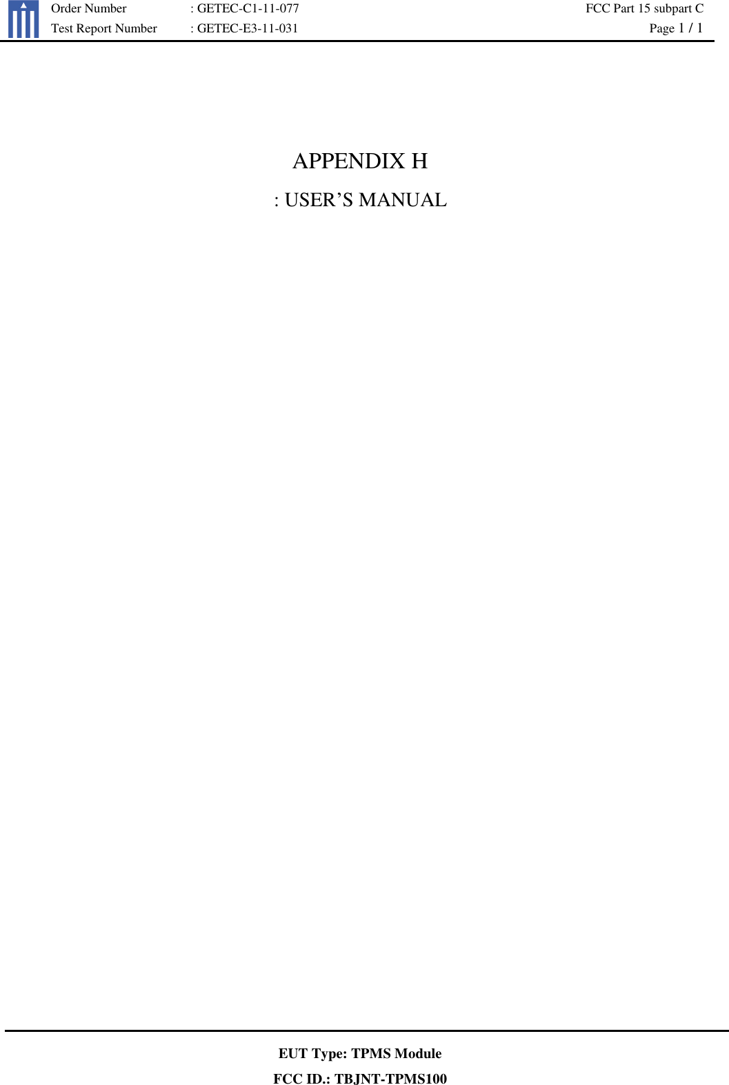
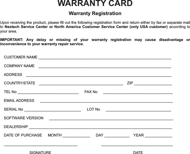
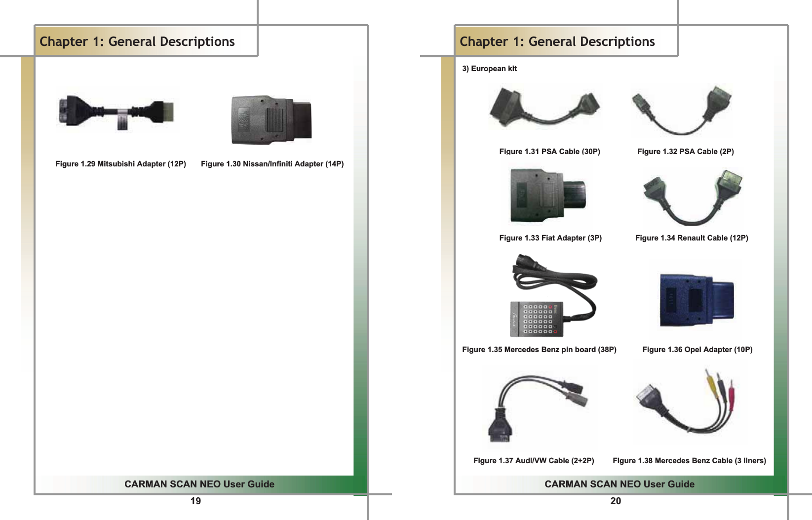
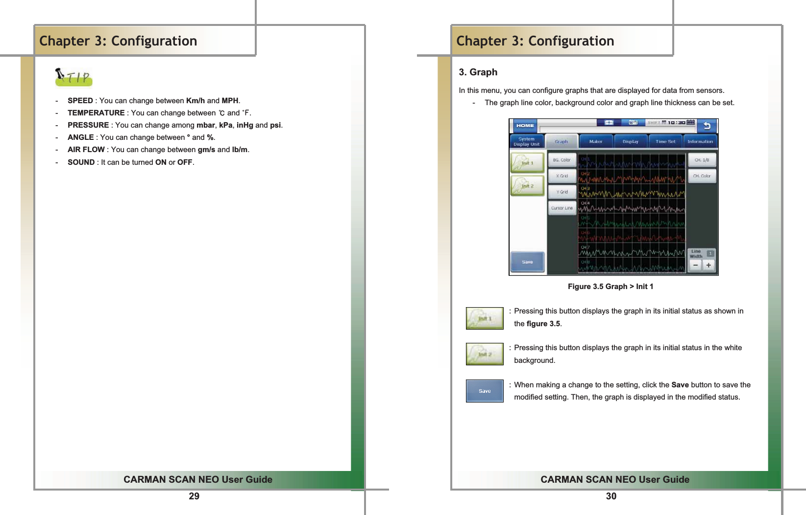
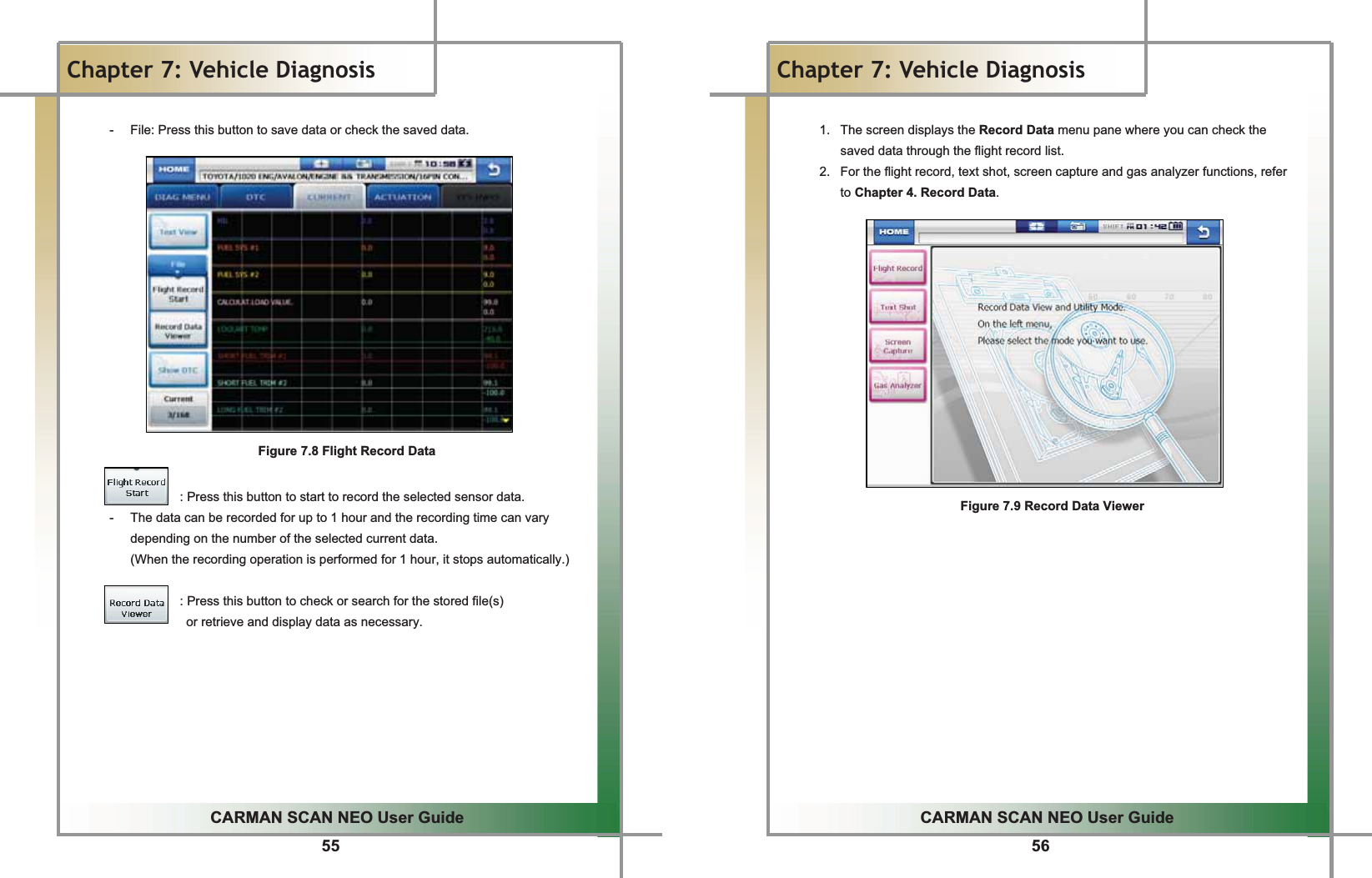
![15GGGGGGGGGGGGGGGGGGGGGGGGGGGGGGGGGGGGGGGGGGGGGGGGGGGGGGGGGGGGGGGGGGGGGGGGGGGGGGGGGGGGGGGGGGGGGGGGGGGGGGGGGGGGGCARMAN SCAN NEO User GuideGGChapter 1: General Descriptions ඞ Oscilloscope Fig 1.12 SCOPE PROBE SET (2-CHANNEL+ EXT) GGGGGGGFig 1.13 TRIGGER PICK UPGGඞ Optional Items [To see pictures of optional items please refer to the attached optional components or visit the website of Nextek Mall www.nex-tek.com.] G16GGCARMAN SCAN NEO User GuideGGChapter 1: General DescriptionsDLC AdapterGThe DLC adapter is used to diagnose vehicles by connecting it to the DLC main connector. As there are similar shaped adapters, make sure to check the vehicle manufacturer name on the adapter before use.GAlso, there can be various adapters for one manufacturer. Therefore, be sure to check the shape and pin numbers of the diagnostic connector in the vehicle.GGSome vehicles do not supply power through the diagnostic connector. Do not connect any power supply if power can be supplied through the diagnostic connector.GG1) Korean kit GGGGGGFigure 1.14 Hyundai/Mitsubishi Cable (12P) Figure 1.15 Kia/Mazda Adapter (6+1P) Figure 1.16 Kia Adapter (20P, blue) Figure 1.17 Daewoo, GM Adapter (12P) Figure 1.18 Ssangyong Adapter (14P) Figure 1.19 Ssangyong Adapter (20P)](https://usermanual.wiki/NEXTECH/NT-TPMS100/User-Guide-1451426-Page-14.png)
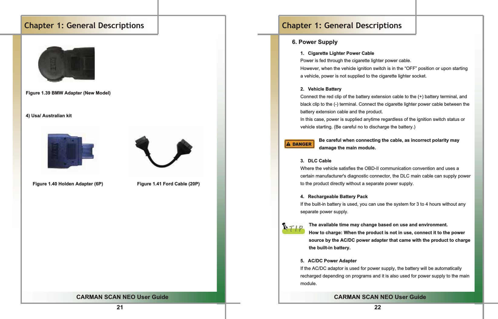
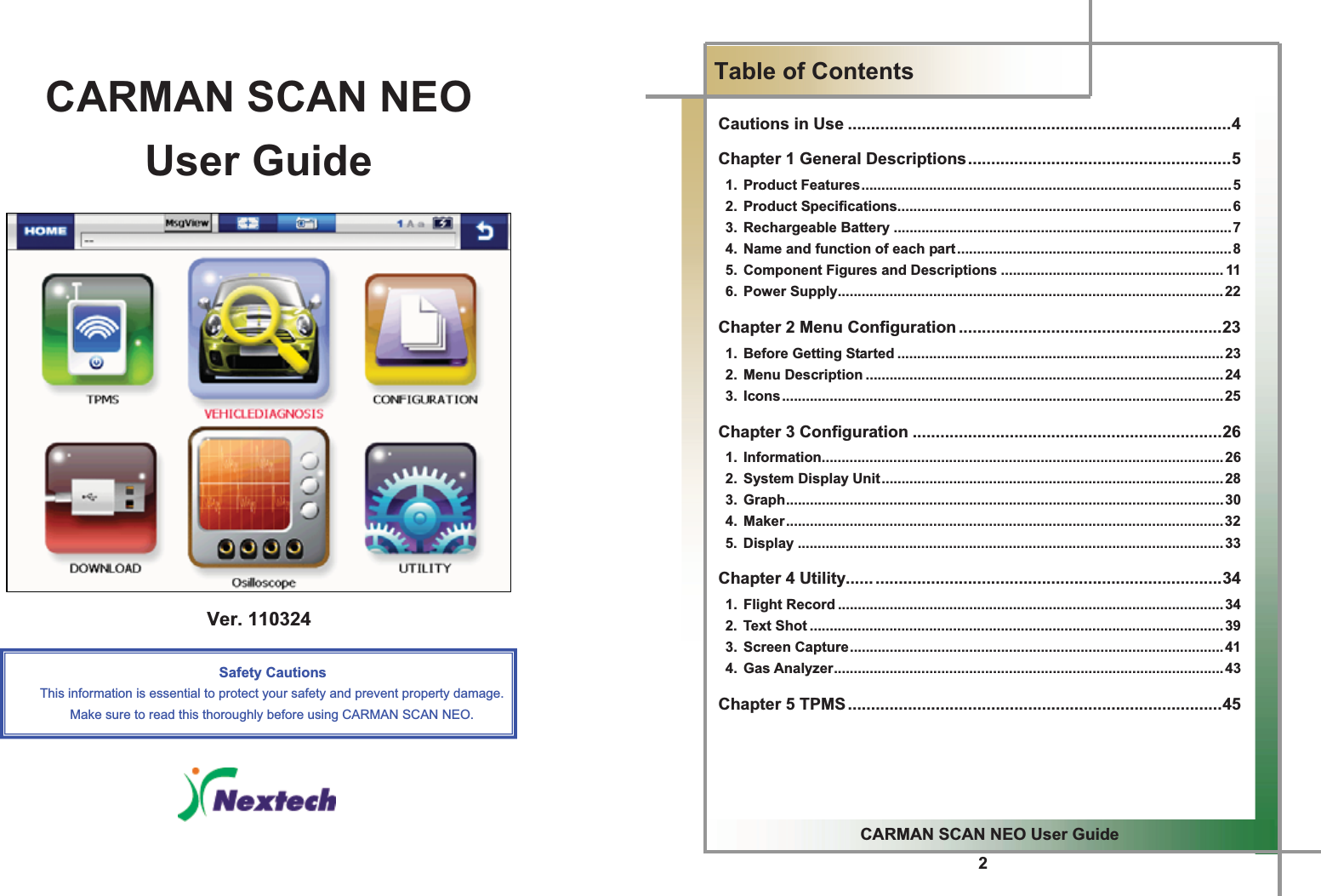
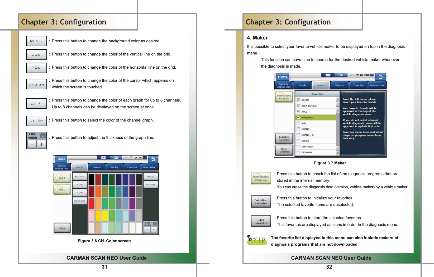
![25GGCARMAN SCAN NEO User GuideGGChapter 2: Menu Configuration3. IconsGWhen turning ON CARMAN SCAN NEO, the main screen with the menu is displayed as follow:GGGGGXG G G G G G G G G G G G G G G YG G G G G G G G G G G G G G G ZG G G G G G G G [G G G G G G G G G G G G G \G G G G G ]G G G G G ^G G G G GFigure 2.2 IconsGG1. HOME - Pressing this button returns to the main screen in the initial booted status. 2. Path Box - This displays the path of the currently running function. 3. Text Shot - Pressing this icon can store all current data values of a system being diagnosed. 4. Screen Capture - The screen being displayed on the LCD can be taken and stored. 5. Text Mode 6. Battery Charging Status - This shows the charging status of the built-in battery. : The status of an external DC power is supplied and at the same time indicates the status of being charged. : Displays the battery status After charging the battery, use AT in order to avoid discharging. 7. Back - Pressing this button returns to the previous screen. GGGG26GGCARMAN SCAN NEO User GuideGGChapter 3: Configuration 1. Information In this menu, you can check and enter user and system information.GGGGGGGGGGGGGGFigure 3.1 Information > User Info.GG1. Select Information from the Configuration menu.G2. My Profile is displayed and this information can be edited.G- When the cursor blinks on the desired text, click the EDIT button.GGGGGGGGGGGGG](https://usermanual.wiki/NEXTECH/NT-TPMS100/User-Guide-1451426-Page-19.png)
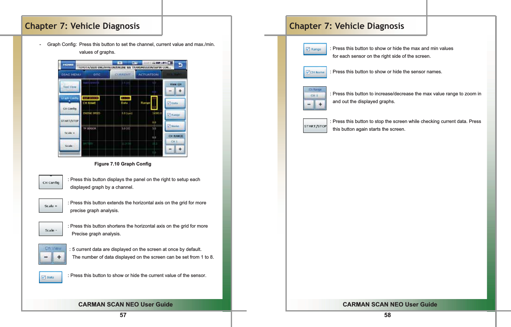
![45GGCARMAN SCAN NEO User GuideGGChapter 5: TPMSGG1. TPMS TPMS should be supported with TPMS module which is optional.G Using TPMS product function please. Register ID after the replacement and repair of tire or wheel.G(But, it can be used with only TPMS system.)GGGGGGGGGGGGGGGGGGGGGGGGGGGGGGGGGGGGGGGGGGGGGGGGGGGGGGGGGGGGGGGGGGGGGGGGGGGGGGGGGGGGGGGGGGGGGFigure 5.1 TPMS .GGGGGGGGGGGGFigure 5.2 TPMS ID REGISTRATION 46GGCARMAN SCAN NEO User GuideGGChapter 6: Diagnosis Menu 1. How To Connect Self-Diagnostic Connector and Select Diagnosis Program (for Korean, Japanese and European vehicles) 1. Locate the diagnostic connector in the vehicle.G- Most vehicles released after year 2002 conform to the OBD-II Protocol and have OBD-II diagnostic connectors.G- Most OBD-II vehicles have their diagnostic connectors on the section over the brake pedal under the steering wheel.G(Figure 6.1)G- If an additional adaptor is required, the scanner display shows the type of the necessary adaptor and the location of the diagnostic connector. (Figure 6.2)GGGGGGGGGGGFigure 6.1 Location of OBD-II Figure 6.2 Adapter and DLC diagnostic connector location guide screenGGG2. Use the diagnosis cable to connect the vehicle's diagnostic connector and CARMAN SCAN NEO.G3. Turn on CARMAN SCAN NEO.G- If power is not feed through the diagnostic connector and the CARMAN SCAN NEO battery is not fully charged, you need to connect an additional power supply (vehicle battery or cigarette lighter power cable, etc).G4. Select the [VEHICLE DIAGNOSIS] menu.GGG](https://usermanual.wiki/NEXTECH/NT-TPMS100/User-Guide-1451426-Page-29.png)
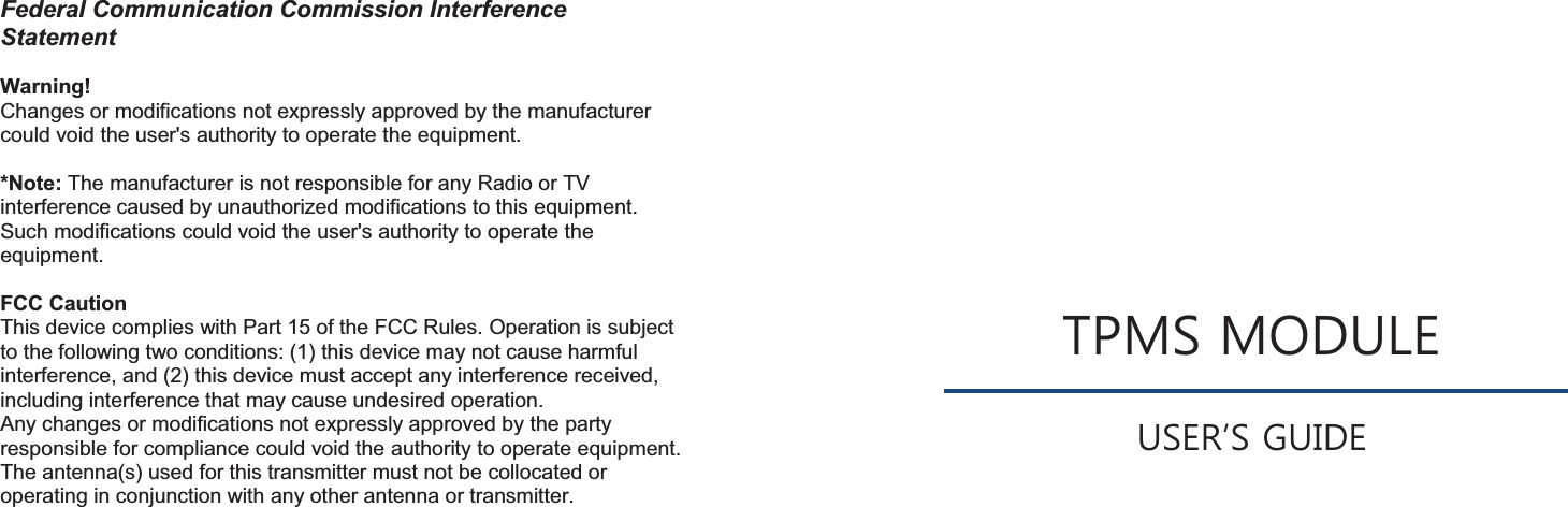
![63GGCARMAN SCAN NEO User GuideGGChapter 8: OSCILLOSCOPE 2. Scope environment setup When [scope] is selected in [Fig. 8.2], the screen in [Fig. 8.3] appears Fig. 8.3 Measurement main screen When icon is clicked in [Fig. 8.3], the screen in [Fig. 8.4] appears ྙ ྛ ྚ Fig. 8.3 Measurement main screenྛ Fig. 8.4 Measurement environment setup screen 64GGCARMAN SCAN NEO User GuideGGChapter 8: OSCILLOSCOPE 1) Waveform display window Fig. 8.5 Waveform display window ත It consists of 4 channels in the middle of the screen and displays waveforms. 2) Environment setup / Measured value window Fig. 8.6 Environment setup / Measured value window ත It is consisted of 4 channels on the right side of the screen, which circulates by icon.. 3) Menu window Fig. 8.7 Menu window ත Area at the bottom of the screen, where the user can choose from various scope](https://usermanual.wiki/NEXTECH/NT-TPMS100/User-Guide-1451426-Page-38.png)