NEXTECH NT-TPMS100 TPMS MODULE User Manual EMISSION TEST REPORT
NEXTECH CO., LTD. TPMS MODULE EMISSION TEST REPORT
NEXTECH >
Users Manual

Order Number
: GETEC-C1-11-077
FCC Part 15 subpart C
Test Report Number
: GETEC-E3-11-031
Page 1 / 1
EUT Type: TPMS Module
FCC ID.: TBJNT-TPMS100
APPENDIX H
: USER’S MANUAL

Federal Communication Commission Interference
Statement
Warning!
Changes or modifications not expressly approved by the manufacturer
could void the user's authority to operate the equipment.
*Note: The manufacturer is not responsible for any Radio or TV
interference caused by unauthorized modifications to this equipment.
Such modifications could void the user's authority to operate the
equipment.
FCC Caution
This device complies with Part 15 of the FCC Rules. Operation is subject
to the following two conditions: (1) this device may not cause harmful
interference, and (2) this device must accept any interference received,
including interference that may cause undesired operation.
Any changes or modifications not expressly approved by the party
responsible for compliance could void the authority to operate equipment.
The antenna(s) used for this transmitter must not be collocated or
operating in conjunction with any other antenna or transmitter.
730602'8/(
86(5Ĝ6*8,'(
+/2146#06016+%'5
7KLVXVHUĜVJXLGHGHVFULEHVKRZWRXVHIRUXVHUVWRXVHPRUHVDIHDQGHDV\
,QFDVHXVHUVGRQRWXVHWKHWRROSURSHUO\LWPD\FDXVHWKHWRROZRUNZURQJDQGDIIHFWWR
XVHUĜVVDIHW\%HVXUHWRUHDGWKLVXVHUĜVJXLGHZHOODQGNHHSWREHXVHGWRKRZWRRSHUDWHZHOO
,QFDVH\RXRSHUDWHWKHWRROZURQJWKHVDIHW\RIXVHUVDQGWRROPD\QRWEHJXDUDQWHHG
ȄG7KHVSHFLILFDWLRQDQGDOOGHWDLOVLQFOXGLQJLQWKLVXVHUĜVJXGHPD\EHFKDQJHGZLWKRXWDQ\
QRWLFHWRDSSURYHLWVTXDOLW\DQGGHVLJQLQIXWXUH
2TGECWVKQPU
z $GUWTGVQWUGVQ%#4/#05%#00'1RTQFWEVQPN[
z 9JGPVJGVQQNKUGSWKRRGFVQ%#4/#05%#00'1DGUWTG%#4/#05%#00'1
UJQWNFDGĜ1((ĝ
z $GUWTGVQOCKPVCKPCFGSWCVGENGCTCPEGCTQWPFVJGVQQN
z 0GXGTFTQRKVCPFFKUCUUGODNGKVYKVJQWVOCPWHCEVWTGTğUKPUVTWEVKQP
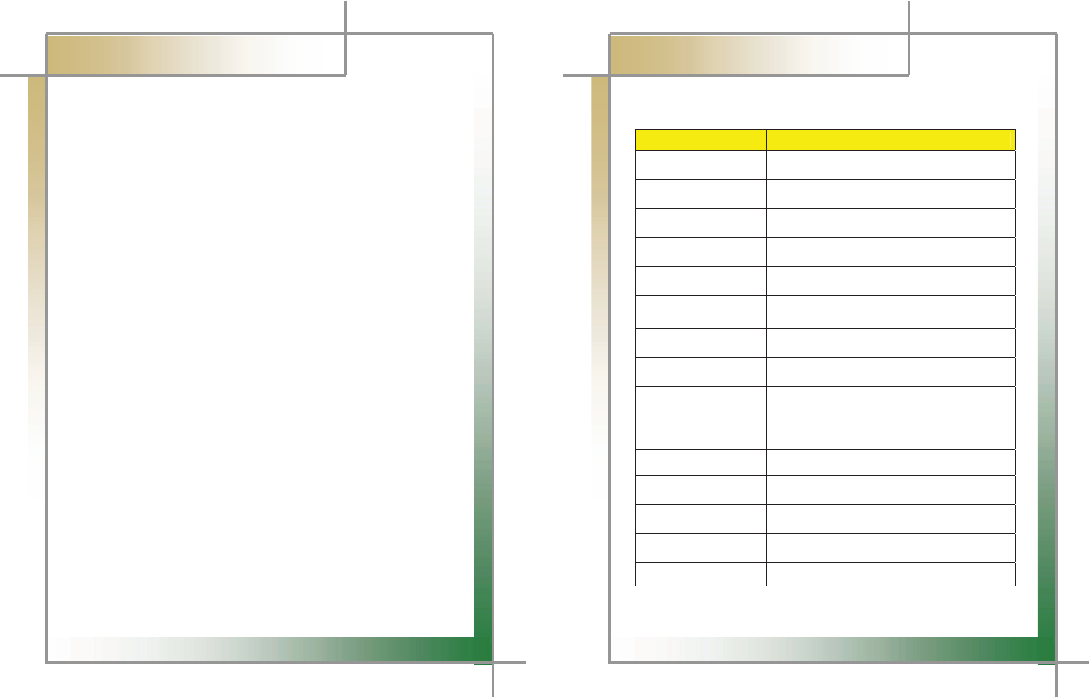
%QORQPGPVCPF5RGEKHKECVKQP
%QORQPGPV2KE
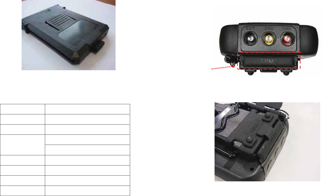
62/5/1&7.'/CKP7PKV
5RGEKHKECVKQP
+VGO 5RGEKHKECVKQP
%27 670)$50ELW&RUWH[0&38
/GOQT[ .E\WH)/$6+0(025<
4(4'%'+8'4
0+]$6.)6.
0+]$6.)6.
.(64#05/+66'4 .+]
1RGTCVKPI6GORGTCVWTG &a&
1RGTCVKPI8QNVCIG '&9ROWa9ROW
5+<' PP[PP[PP
+PUVCNNCVKQP
%HVXUHWRRII&$50$16&$11(2EHIRUH\RXLQVWDOO730602'8/(
,QVWDOO7306PRGXOHWRWKHGLUHFWLRQDVEHORZ7KHODEHOę7306ĚVKRXOGEHXSSHUSRVLWLRQ
DVEHORZDQGLWPD\QRWEHLQVWDOOHGLIWKHGLUHFWLRQLVRSSRVLWH
$ERYHPDUNHGDUHDLVWKHVSDFHWRLQVWDOO7306PRGXOHDQGWKHFDSVKRXOGEHRSHQHGWRࡢ ̐ս
LQVWDOO730602'8/(
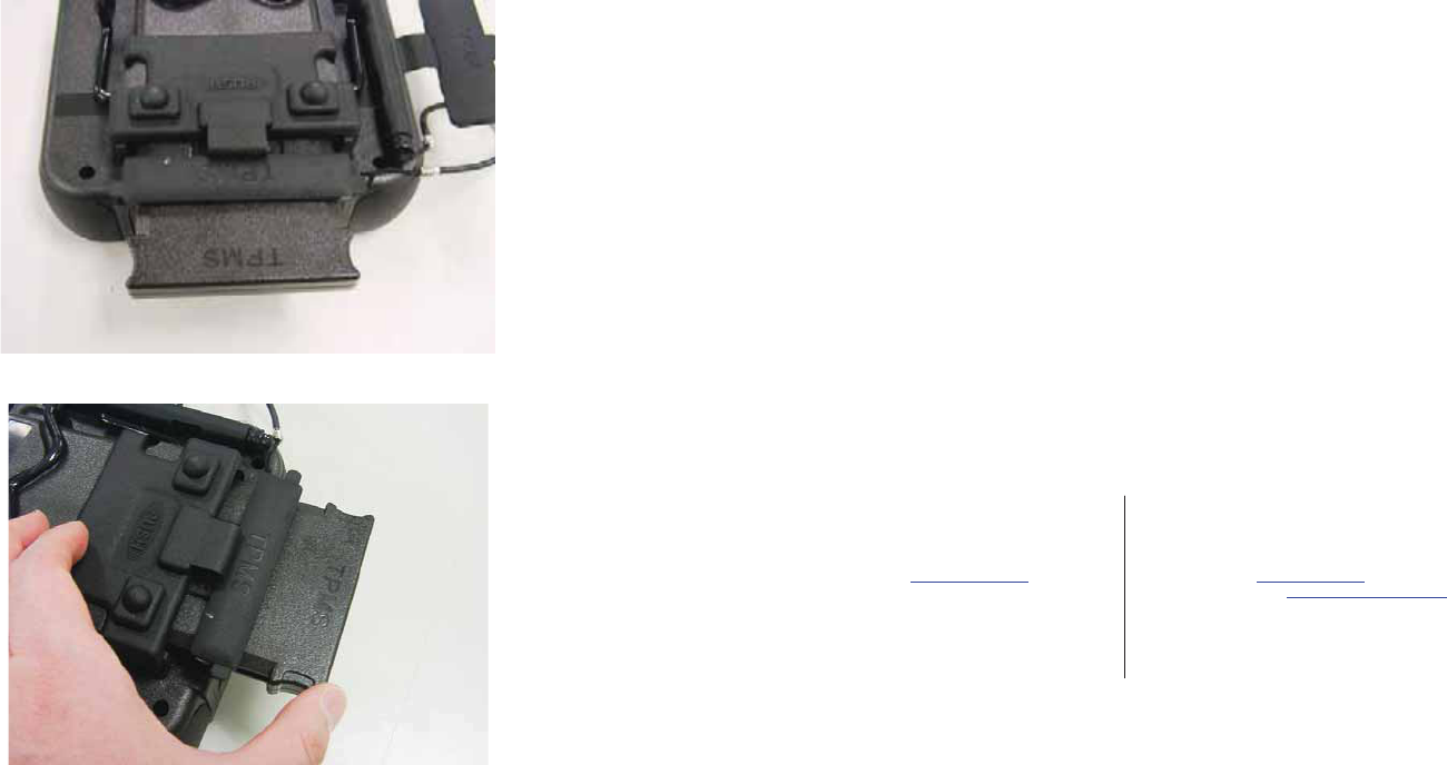
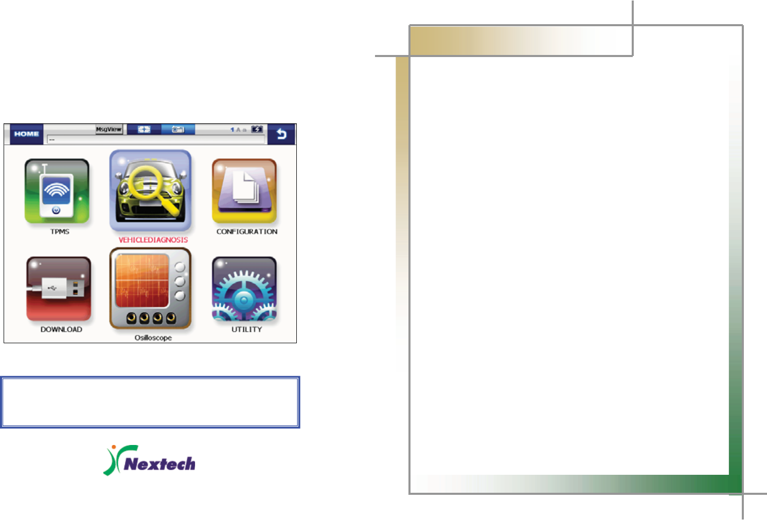
,QVWDOO730602'8/(DVDERYH
3XVKWRWKHHQGWREHLQVWDOOHGWLJKW
:KHQVHSDUDWHGSXVKWKHSDUWODEHOHGę386+ĚDQGVHSDUDWH730602'8/(
1RGTCVKQP
5HIHUWRXVHUĜVJXLGH&KDSWHU7306DQGRSHUDWHLW
WARRANTY CARD
Warranty Policy
1. The manufacturer warrants this product to be defect free in material and workmanship for a period of one (1)
year from the date of purchase. Defective products may be returned by the original purchaser within the
warranty period, postage pre-paid together with proof of purchase date to Nextech Co. LTD. Defective
products will be repaired at manufacturer’s discretion, replaced at no charge.
2. The warranty does not apply to any units that have been tampered with, or to damages incurred through
improper use and care, defects caused by abuse or through the usage for purposes other than the intended
use, used in a manner inconsistent with the instructions regarding use, and faulty packing or mishandling by
any common carrier.
3. Repairs not covered by this warranty will be performed at the current cost for parts and labor. In no event will
Nextech Co. Ltd’s liability exceed the price paid for the product from direct, indirect, special, incidental or,
consequential damages resulting from the use of this product, its accompanying software, or its documentation
without obligation to notify any individual or entity. Warranties hereunder extend only to customers and are not
transferable.
Warranty Period & Software update
1. Warranty period for Nextech products and these’s accessories including software card is one (1) year from the
date of sale to the original consumer.
2. Free Software update for Nextech products is one (1) year from date of purchase. After one (1) year from
purchase date, software updates will be optional and will require separate payment per request.
Repair Service
1. If you suspect that you have a problem with this product, please read the operation manual (guide) carefully to
ensure that you are operating this product properly.
2. If you conclude that a real problem exists, check your product according to the procedures on the “Trouble
Shooting Card” and mark your trial records in the blank.
3. Please return the main body or the troubled parts along with the “Trouble Shooting Card” to the repair service
center listed below. Be sure to return them in freight prepaid as we don’t accept freight collect.
Nextech Service Center North America Customer Service Center
Nextech Co. Ltd. Nextech America Inc.
E&C Venture Dream Tower(the 3rd) 13F 17581 Irvine Blvd suite 100
Guro-dong, 197-33 Guro-Gu, Seoul, Korea Tustin CA, 92780 USA
Tel : (822)3140-1489 Fax : (822)3140-1449 Tel: (714)832-0100 Fax: (714)832-0123
Email : sales@nex-tek.com Email: csh@nex-tek.com
kkanggri@nex-tek.com Website: www.nex-tech.com/carman

WARRANTY CARD
Warranty Registration
Upon receiving the product, please fill out the following registration form and return either by fax or separate mail
to Nextech Service Center or North America Customer Service Center (only USA customer) according to
your area.
IMPORTANT: Any delay or missing of your warranty registration may cause disadvantage or
inconvenience to your warranty repair service.
CUSTOMER NAME _______________________________________________________________
COMPANY NAME _______________________________________________________________
ADDRESS _____________________________________________________________________
COUNTRY/STATE ________________________________________ ZIP __________________
TEL No _____________________________ FAX No _________________________________
EMAIL ADDRESS _______________________________________________________________
SERIAL No ___________________________ LOT No _______________________________
SOFTWARE VERSION ___________________________________________________________
DEALERSHIP ____________________________________________________________________
DATE OF PURCHASE MONTH _____________ DAY ____________ YEAR _____________
___________________________________ __________________________________
SIGNATURE DATE
1
G
CARMAN SCAN NEO
User Guide
Ver. 110324
Safety Cautions
This information is essential to protect your safety and prevent property damage.
Make sure to read this thoroughly before using CARMAN SCAN NEO.
G
G
G
G
G2
G
G
CARMAN SCAN NEO User Guide
G
Table of ContentsG
Cautions in Use ...................................................................................4
Chapter 1 General Descriptions.........................................................5
1. Product Features............................................................................................. 5
2. Product Specifications....................................................................................6
3. Rechargeable Battery .....................................................................................7
4. Name and function of each part..................................................................... 8
5. Component Figures and Descriptions ........................................................ 11
6. Power Supply................................................................................................. 22
Chapter 2 Menu Configuration .........................................................23
1. Before Getting Started .................................................................................. 23
2. Menu Description ..........................................................................................24
3. Icons...............................................................................................................25
Chapter 3 Configuration ...................................................................26
1. Information.....................................................................................................26
2. System Display Unit...................................................................................... 28
3. Graph..............................................................................................................30
4. Maker..............................................................................................................32
5. Display ...........................................................................................................33
Chapter 4 Utility.................................................................................34
1. Flight Record .................................................................................................34
2. Text Shot ........................................................................................................ 39
3. Screen Capture.............................................................................................. 41
4. Gas Analyzer.................................................................................................. 43
Chapter 5 TPMS .................................................................................45
3
G
G
CARMAN SCAN NEO User GuideG
G
Table of contentsG
Chapter 6 Diagnosis Menu ...............................................................46
1. How To Connect Self-Diagnostic Connector and Select
Diagnosis Program ....................................................................................... 46
Chapter 7 Vehicle Diagnosis ............................................................49
1. Diagnostic Trouble Codes ............................................................................49
2. Current Data...................................................................................................52
3. Actuation........................................................................................................60
Chapter 8 Osilloscope.......................................................................62
1. Main Menu......................................................................................................62
2. Scope environment setup............................................................................. 63
3. Description of scope environment setup icons...........................................65
Q & A....................................................................................................66
WARRANTY CARD..............................................................................67
G
4
G
G
CARMAN SCAN NEO User GuideG
G
Cautions in useG
Safety Instruction
G G
Cautions in Use
CARMAN SCAN NEO mentioned in this User's Guide is designed for those who have
basic qualifications for using this system.
Users should follow the safety instructions for safe and efficient use of the product.
The cautions of use are as follows:
Do not drop CARMAN SCAN NEO.
Always use it in the rubber shroud to product it.
Do not place CARMAN SCAN NEO on the power distributor.
Although CARMAN SCAN NEO is manufactured to internally prevent
the interference from the electromagnetic waves, the strong interference
by excessive electromagnetic waves may damage the product.
Excessive surge or electric shock fed by a power cable may damage
the power supply system of CARMAN SCAN NEO.
So, do not use the product while the power supply is unstable.
The voltage rating of the AC/DC adapter is 12V DC.
Be sure to use an AC/DC adaptor with the rated voltage.
Be careful not to let water or oil get into the product.
The product can be severely damaged.
Be sure to use the USB cable supplied by Our Company only.
Otherwise, your PC or product can be damaged.
5
G
G
CARMAN SCAN NEO User GuideG
G
Chapter 1: General Descriptions
1. Product Features
CARMAN SCAN NEO can check vehicle ECU information and malfunction status through
the OBD-I, OBD-II and CAN communication.
You can connect CARMAN SCAN NEO to the vehicle diagnostic connector with a
diagnosis cable to check if any of the engine, automatic transmission, ABS, air bag, power
steering and other devices has an error, view current data and use actuator drive features.
CARMAN SCAN NEO has the following features:
ඖ Diagnoses Korean, Japanese and European vehicles.
- OBD-I , OBD-II, MOBD(ISO 9141-2, SAE-J1850, KWP-2000, CAN, SAE J1587)
ඖ Supports vehicle troubleshooting and current data search.
- You can diagnose vehicles with their sensors and switches, and save and reload
the current data.
ඖ Supports automatic actuator inspection.
- This function runs/stops the actuator and switches forcibly in order to check if the
corresponding active device is normal.
ඖ You can save data and upgrade the diagnosis program by connecting the product to
your PC.
ඖ You can change the sound effects and display unit of the CARMAN SCAN NEO.
ඖ Provides the LCD brightness adjustment function.
ඖ With the built-in battery, you can perform diagnosis without an additional power
supply. (for vehicles without DLC power)
G
6
G
G
CARMAN SCAN NEO User GuideG
G
Chapter 1: General Descriptions
2. Product Specifications
G
Item Detail Specifications
CPU PXA-320 806MHz
O.S Window CE 5.0
LCD 5.7 inch (Color / Touch Screen)
Connectivity USB (USB 2.0 / Compliant)
Operating Temperature -10 ~ 60
Operating Voltage 8 ~ 32V
Function TPMS / VIDEO(Composite) / Input(PAL,NTSC)
User Interface Touch Screen & Multi Keyboard
Protocol
KWP 2000, ISO 9141-2, J1850(VPW,PWM)
Dual Wire CAN(2.0A, 2.0B) J1587,
Single Wire CAN, Hi Speed Serial
Maximum Sample Rate 25[MHz/S] per Channel
Volt / division 10m[V] to 100[V] in a 1, 2.5, 5 Sequence
Scope Time Setting 1[༕] ~ 10[S]
Input Impedance 1[M]
Battery Li-Polymer 7.4[V] 4200[mA]
G
7
G
G
CARMAN SCAN NEO User GuideG
G
Chapter 1: General Descriptions
3. Rechargeable Battery
* The rechargeable battery pack has the following features
T Voltage of the rechargeable battery pack gradually decreases even when the
system does not run.
T Before using the product for the first time, be sure to fully charge the battery.
Always use the rechargeable battery pack provided by Our Company.
- Using a 3rd party product may cause explosion.
(7.4V 2200 mAh lithium ion battery pack)
Do not heat the rechargeable battery pack.
- It may cause explosion.
Do not short the battery pack terminal.
- It may cause explosion.
Do not place the battery pack on or near hot material over 60ºC.
- It may cause explosion.
Keep the battery pack away from touch of children or an animal.
- It may cause a fire or injury.
To prevent the battery pack from being discharged, always connect
the power source before using the system. Screen captures, flight
record and other information can be erased due to the discharged
battery pack.
The rechargeable battery pack is a consumable product and is
under warranty for 6 months after purchase.
G
G
G
G
8
G
G
CARMAN SCAN NEO User GuideG
G
Chapter 1: General Descriptions
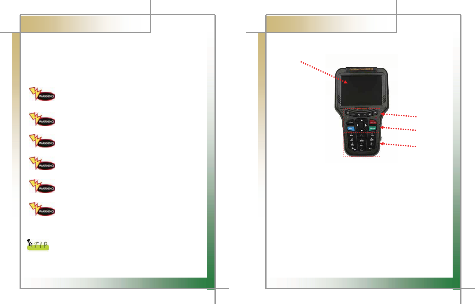
4. Name and function of each part
ඞ
Front View of Main Body
1
2
3
4
Fig. 1.1 Main Body
Touch screen LCD panel
Touch a button or others on the LCD screen with a touch pen or finger to activate a
function.
Function keys (F1~F6)
You can use these keys to clear trouble codes, view help, fix Current Data
selection, etc.
ENTER key & Arrow key
Use this key to execute the command you have chosen.
Use this key to move cursor to the left/right/upper/lower sides.
Numeric key (0~9)
Use this key to enter cylinder serial number when you replace the injector or to
enter numbers such as immobilizer password.
9
G
G
CARMAN SCAN NEO User GuideG
G
Chapter 1: General Descriptions
ඞ
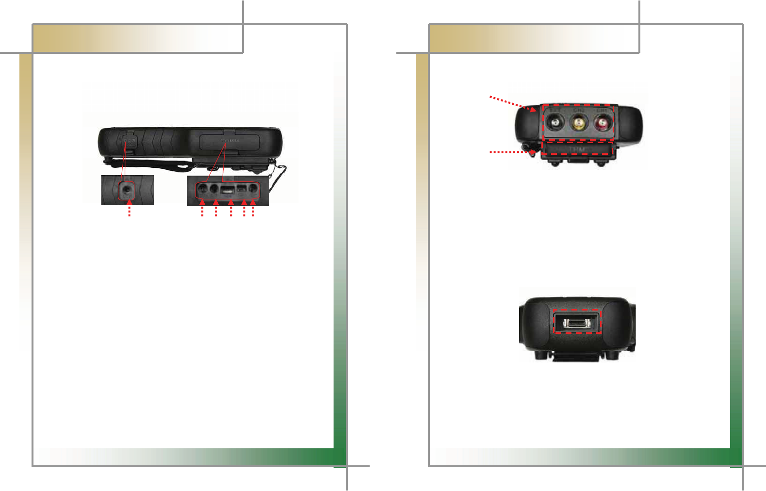
Right Side of Main Body
1 2 3 4 5 6
Fig. 1.2 Right Side of Main Body
1) Power Connector
A connector for connection to AC/DC POWER adaptor.
2) J2534
Reprogram port
3) RS 232 Connector
A connector for RS 232 cable on gas analyzer
4) , 5) USB Connector
This is used when you connect CARMAN SCAN NEO to a PC to download the
diagnosis program.
6) Endoscope CAM Connector
GG
10
G
G
CARMAN SCAN NEO User GuideG
G
Chapter 1: General Descriptions
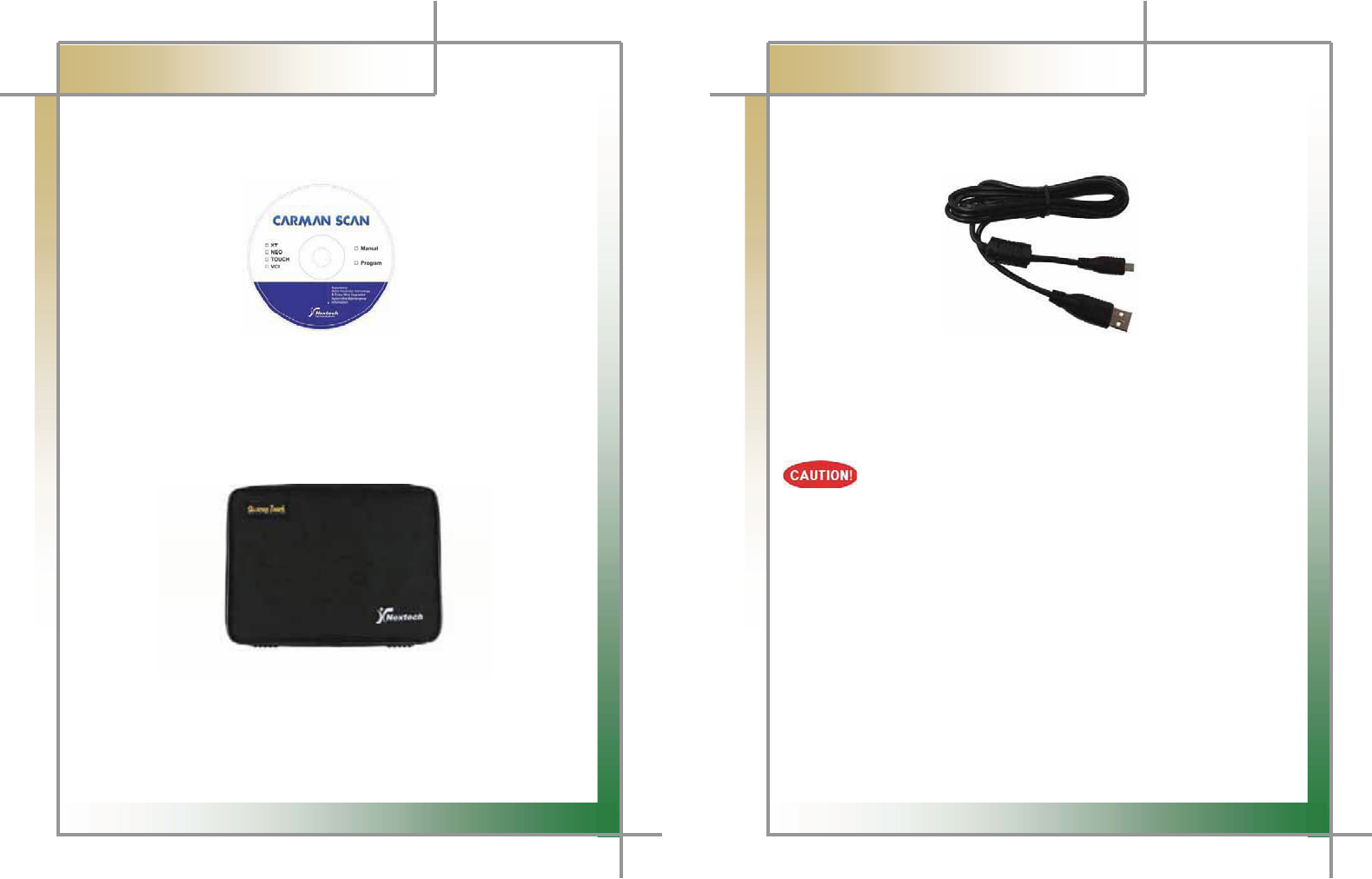
ඞ
Upper part of Main Body
1
2
Fig. 1.3 Upper part of Main Body
1) Scope Cable Terminal
- 1 ~ 4 CH : terminal to measure waveform, ignition, and other options (temperature,
pressure, electric current, etc)
- EXT CH : terminal to use Multimeter, Simulator, Actuator, and EXT Trigger
2) TPMS
ඞ
Low part of Main Body
Fig. 1.4 Low part of Main Body
1) DLC Communication Cable Connector
A connector for connection to the DLC communication cable for vehicle diagnosis.
Always use DLC communication cable provided with this product.
11
G
G
CARMAN SCAN NEO User GuideG
G
Chapter 1: General Descriptions
5. Component Figures and Descriptions
ඞ
User Guide
Figure 1.5 CARMAN SCAN NEO User Guide
ඞ
Carrying Case
Fig. 1.6 CARMAN SCAN NEO Carrying CaseG
G
CARMAN SCAN NEO includes a number of adaptors and cables for diagnosing vehicles.G
When the product is not in use, store it in the supplied carrying case to prevent damage
and loss.G
12
G
G
CARMAN SCAN NEO User GuideG
G
Chapter 1: General Descriptions
ඞ
USB Cable
G
G
G
G
G
G
G
G
G
GG
G
Fig. 1.7 USB CableG
G
The USB cable connects the USB ports of CARMAN SCAN NEO and your PC to download
the diagnosis software or save captured files to your PC.G
G
GBe sure to use the USB cable supplied by Our Company only.
Otherwise, your PC or product can be damaged.G
GGGGGGGGGGGGGGGGGGGGGGGGGGGGGGGGGGGGGGGGGGGGGGGGGGGGGGGGGGGGGGGGGGGGGGGGGGGGGGGGGGG
13
G
G
CARMAN SCAN NEO User GuideG
G
Chapter 1: General Descriptions
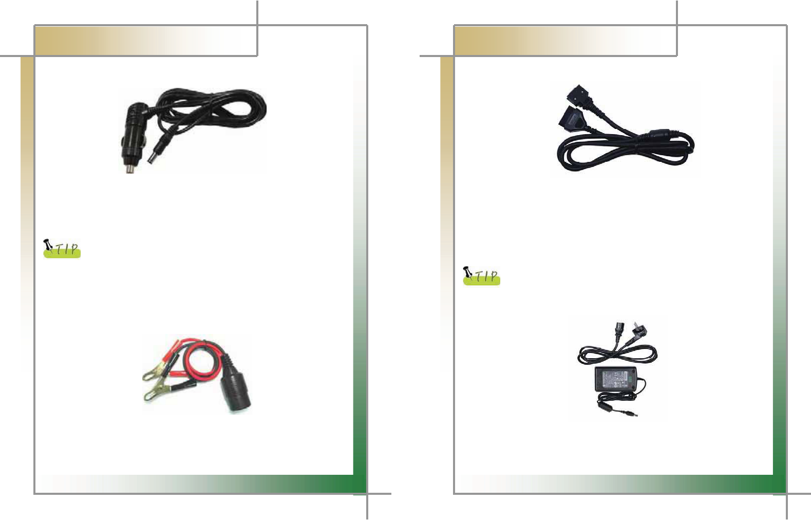
ඞ
Cigarette Lighter Power Cable
G
G
G
G
G
G
G
G
G
Fig. 1.8 Cigarette Lighter Power CableG
G
The cigarette lighter power cable connects CARMAN SCAN NEO with the cigarette lighter
jack in your vehicle to feed power to CARMAN SCAN NEO.G
G
CARMAN SCAN NEO has a built-in battery so that you can use it without
an additional power supply. When the battery power is weak or the
battery is not charged, you can feed power by connecting the main
module to the vehicle power source through the cigarette lighter power
cable.
G
G
ඞٻ
Battery Extension Cable
G
G
G
G
G
G
G
G
Fig. 1.9 Battery Extension Cable
G
G
The battery extension cable is used to feed power to CARMAN SCAN NEO directly from a
vehicle battery through the cigarette lighter power cable.G
14
G
G
CARMAN SCAN NEO User GuideG
G
Chapter 1: General Descriptions
G
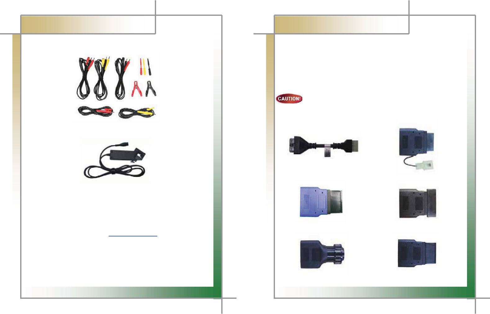
ඞ
GDLC Cable
G
G
G
G
G
G
G
G
G
Fig. 1.10 DLC Cable
G
G
The DLC cable is also called the OBD-II cable. All vehicles released recently have built-in
OBD-II connectors compatible to the OBD-II specification.G
It is possible to diagnose new model vehicles by directly connecting the DLC cable. It is not
necessary to connect any additional power source as power is feed through the diagnostic
connector.G
G
Old model vehicles should be diagnosed by connecting an additional
adapter.
G
G
ඞٻ
AC electrical power cord / adapterG
G
G
G
G
G
G
G
G
G
Fig 1.11 AC electrical power cord / adapterG
When you want to download the diagnosis program or search flight record, you can use
this AC/DC electrical power adapter to feed power.G
A
lso, can char
g
e the batter
y
built in the
p
roduct.G
15
GGGGGGGGGGGGGGGGGGGGGGGGGGGGGGGGGGGGGGGGGGGGGGGGGGGGGGGGGGGGGGGGGGGGGGGGGGGGGGGGGGGGGGGGGGGGGGGGGGGGGGGGGGGG
G
CARMAN SCAN NEO User GuideG
G
Chapter 1: General Descriptions
ඞ
Oscilloscope
Fig 1.12 SCOPE PROBE SET (2-CHANNEL+ EXT)
G
G
G
G
G
G
G
Fig 1.13 TRIGGER PICK UP
G
G
ඞ
Optional Items
[To see pictures of optional items please refer to the attached
optional components or visit the website of
Nextek Mall www.nex-tek.com.]
G
16
G
G
CARMAN SCAN NEO User GuideG
G
Chapter 1: General Descriptions
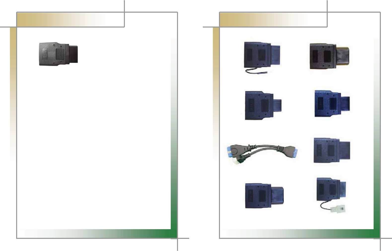
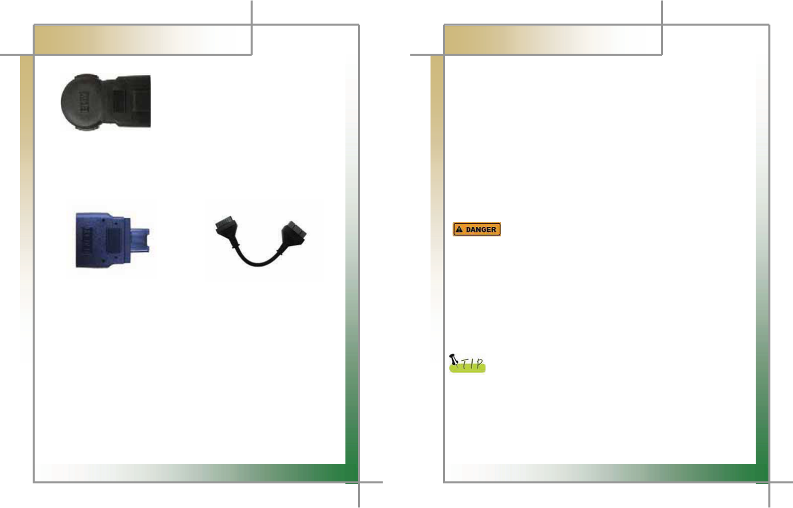
DLC Adapter
G
The DLC adapter is used to diagnose vehicles by connecting it to the DLC main connector.
As there are similar shaped adapters, make sure to check the vehicle manufacturer name
on the adapter before use.G
Also, there can be various adapters for one manufacturer. Therefore, be sure to check the
shape and pin numbers of the diagnostic connector in the vehicle.G
G
Some vehicles do not supply power through the diagnostic connector.
Do not connect any power supply if power can be supplied through the
diagnostic connector.
G
G
1) Korean kit
G
G
G
G
G
G
Figure 1.14 Hyundai/Mitsubishi Cable (12P) Figure 1.15 Kia/Mazda Adapter (6+1P)
Figure 1.16 Kia Adapter (20P, blue) Figure 1.17 Daewoo, GM Adapter (12P)
Figure 1.18 Ssangyong Adapter (14P) Figure 1.19 Ssangyong Adapter (20P)
17
G
G
CARMAN SCAN NEO User GuideG
G
Chapter 1: General Descriptions
G
G
G
G
G
G
G
G
Figure 1.20 Samsung Adapter (14P)G
G
G
G
G
G
G
G
18
G
G
CARMAN SCAN NEO User GuideG
G
Chapter 1: General Descriptions
2) Japanese kit
G
G
G
G
G
G
G
G
Figure 1.21 Toyota Adapter (17R) Figure 1.22 Toyota Adapter (17C)G
G
G
G
G
G
G
G
Figure 1.23 Honda Adapter (3P) Figure 1.24 Honda Adapter (5P)
G
G
G
G
G
G
G
Figure 1.25 Mitsubishi Cable (12+16P) Figure 1.26 Subaru Adapter (9P)
G
G G G G G
G
G
G
G
G
G
Figure 1.27 Mazda Adapter (17C) Figure 1.28 Mazda Adapter (6+1P)
G
G
19
G
G
CARMAN SCAN NEO User GuideG
G
Chapter 1: General Descriptions
G
G
G
G
G
G
G
G
Figure 1.29 Mitsubishi Adapter (12P) Figure 1.30 Nissan/Infiniti Adapter (14P)G
G
G
G
G
G
G
G
G
G G
20
G
G
CARMAN SCAN NEO User GuideG
G
Chapter 1: General Descriptions
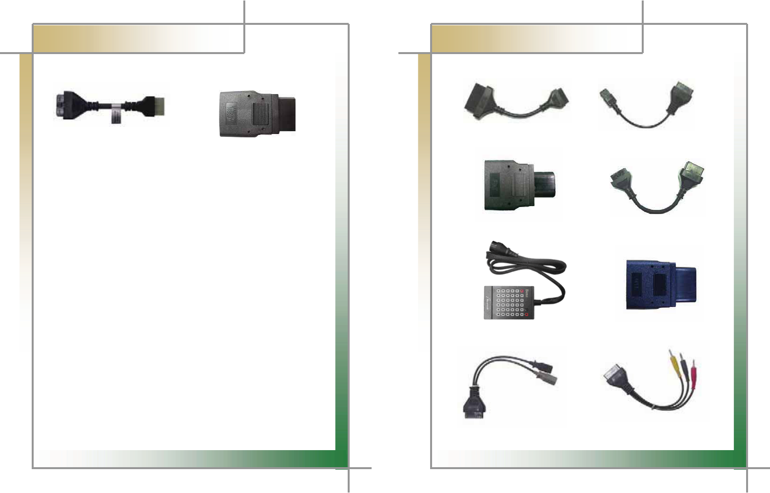
3) European kit
G
G
G
G
G
G
G
Figure 1.31 PSA Cable (30P) Figure 1.32 PSA Cable (2P)G
G
G
G
G
G
G
Figure 1.33 Fiat Adapter (3P) Figure 1.34 Renault Cable (12P)
G
G
G
G
G
G
G
G
G
Figure 1.35 Mercedes Benz pin board (38P) Figure 1.36 Opel Adapter (10P)
G
G
G
G
G
G
G
G
G
Figure 1.37 Audi/VW Cable (2+2P) Figure 1.38 Mercedes Benz Cable (3 liners)
G
21
G
G
CARMAN SCAN NEO User GuideG
G
Chapter 1: General Descriptions
G
G
G
G
G
G
G
Figure 1.39 BMW Adapter (New Model)
G
G
G
4) Usa/ Australian kit
G
G
G
G
G
G
G
G
G
Figure 1.40 Holden Adapter (6P) Figure 1.41 Ford Cable (20P)
G
22
G
G
CARMAN SCAN NEO User GuideG
G
Chapter 1: General Descriptions
6. Power Supply
1. Cigarette Lighter Power Cable
G
Power is fed through the cigarette lighter power cable.GG
However, when the vehicle ignition switch is in the “OFF” position or upon starting
a vehicle, power is not supplied to the cigarette lighter socket.G
G
2. Vehicle Battery
G
Connect the red clip of the battery extension cable to the (+) battery terminal, and
black clip to the (-) terminal. Connect the cigarette lighter power cable between the
battery extension cable and the product.G
In this case, power is supplied anytime regardless of the ignition switch status or
vehicle starting. (Be careful no to discharge the battery.)G
G
Be careful when connecting the cable, as incorrect polarity may
damage the main module.
G
G
3. DLC Cable
G
Where the vehicle satisfies the OBD-II communication convention and uses a
certain manufacturer's diagnostic connector, the DLC main cable can supply power
to the product directly without a separate power supply.G
G
4. Rechargeable Battery Pack
G
If the built-in battery is used, you can use the system for 3 to 4 hours without any
separate power supply.G
G
The available time may change based on use and environment.
G
How to charge:
G
When the product is not in use, connect it to the power
source by the AC/DC power adapter that came with the product to charge
the built-in battery.
G
G
5. AC/DC Power Adapter
G
If the AC/DC adaptor is used for power supply, the battery will be automatically
recharged depending on programs and it is also used for power supply to the main
module.G
23
G
G
CARMAN SCAN NEO User GuideG
G
Chapter 2: Menu Configuration
1. Before Getting Started
G
1. Before using the system, check whether or not the battery is fully charged. If it is not
charged, then connect external power supply or recharge the battery before using the
system.G
- If you use the system by connecting it to a vehicle, you can also feed power to it
through the vehicle diagnostic connector.
G
If power is not feed by the vehicle diagnostic connector, you need to
connect the cigarette lighter power cable to feed power before you
start communication with the vehicle. Voltage mismatch between the
ECU and CARMAN SCAN NEO may cause a communication error.G
G
2. Before using the system, make sure to download the diagnosis program.G
The diagnosis program will be stored in the system memory.G
- Before using the system, check if the diagnosis program matches the option you
have purchased.G
G
G
G
G
G
G
G
G
G
G
G
G
G
G
G
G
24
G
G
CARMAN SCAN NEO User GuideG
G
Chapter 2: Menu Configuration
2. Menu Description
G
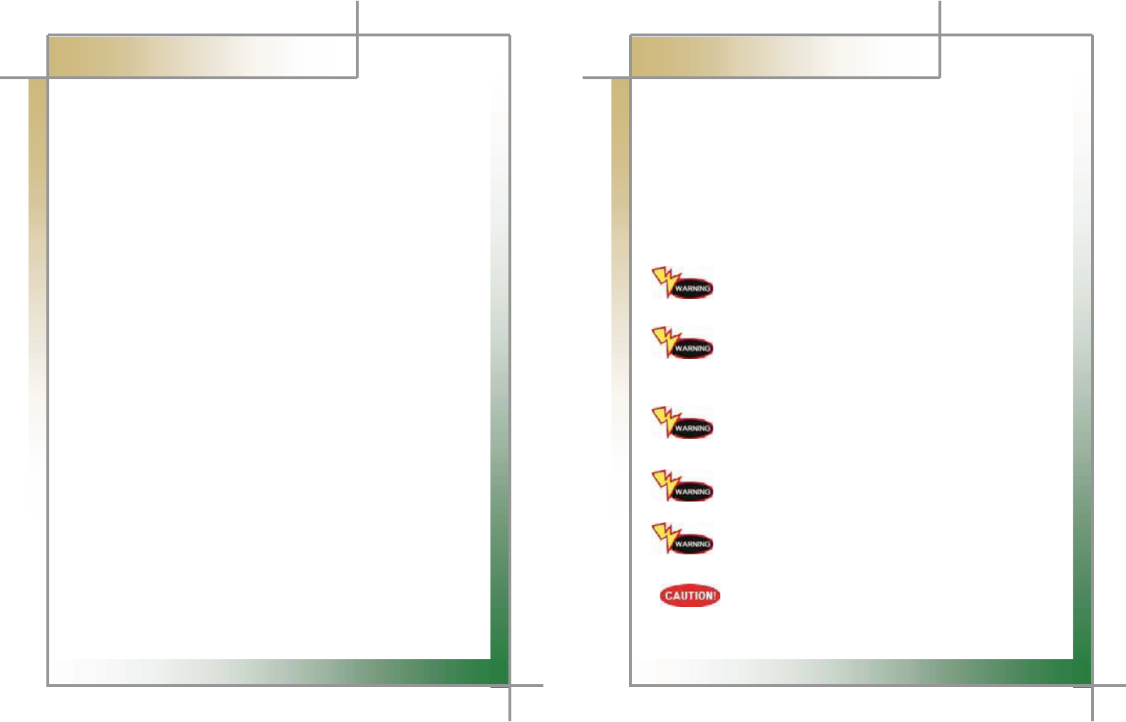
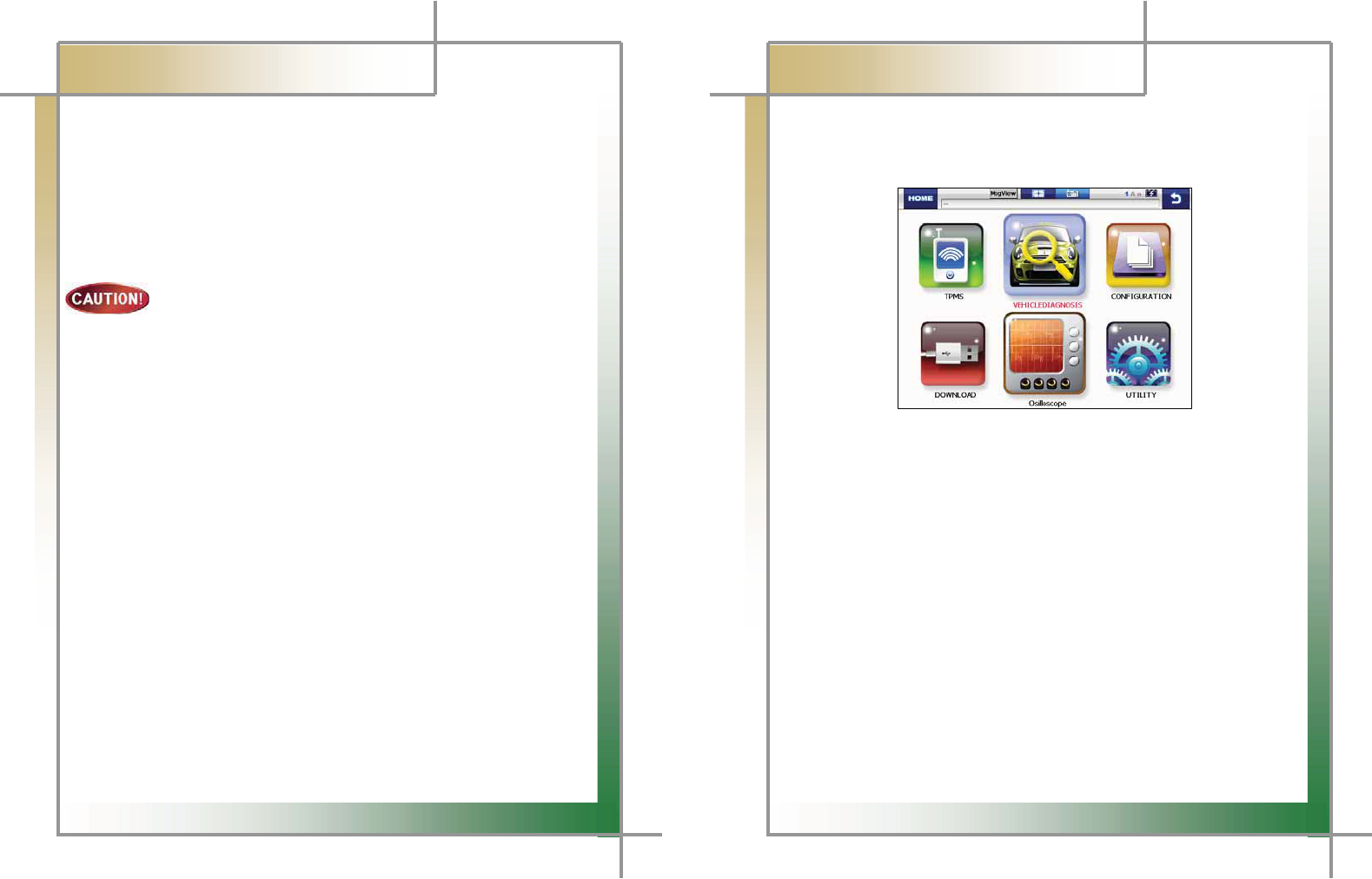
When turning ON CARMAN SCAN NEO, the main screen with the menu is displayed as
follow.
G
G
G
G
G
G
GGGGGGGGGGGGGGGGGGGGGGGGGGGGGGGGGGGGGGGGGGGGGGGGGGGGGGGGGGGGGGGGGGGG
G
Figure 2.1 Main ScreenG
1) TPMS
- TPMS should be supported with TPMS module which is optional.G
2) VEHICLE DIAGNOSIS
- This menu provides scanner's own functionality such as vehicle diagnosis, service
data search, actuator activation, etc.
3) CONFIGURATION
- In this menu, you can check the system display unit, graph, background color,
favorite setting, screen setting, time setting and system information.
4) DOWNLOAD
- In this menu, you can connect to the download program to update the software in
CARMAN SCAN NEO.
5) OSCILLOSCOPE
- It can measure desired sensor waveform and ignition waveform
with 4 channels, and use meter & simulator function.
6) UTILITY
- You can check flight record, text shot and screen capture and use gas analyzer
function.
25
G
G
CARMAN SCAN NEO User GuideG
G
Chapter 2: Menu Configuration
3. Icons
G
When turning ON CARMAN SCAN NEO, the main screen with the menu is displayed as
follow:G
G
G
G
G
XG G G G G G G G G G G G G G G YG G G G G G G G G G G G G G G ZG G G G G G G G [G G G G G G G G G G G G G \G G G G G ]G G G G G ^G G G G G
Figure 2.2 IconsG
G
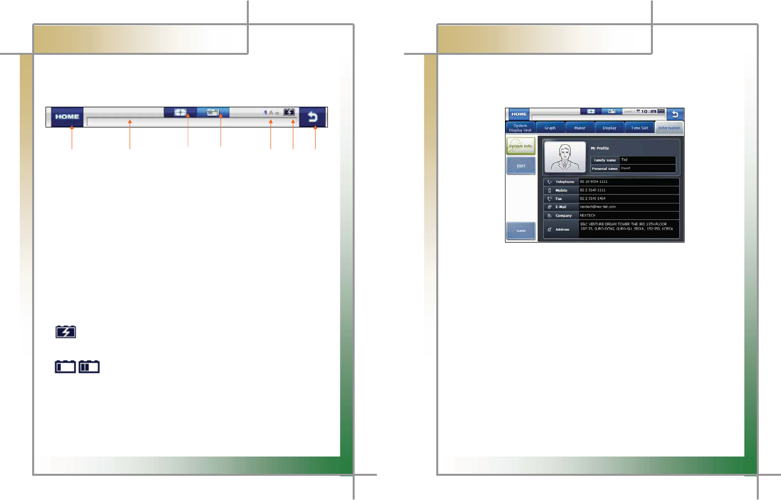
1. HOME
- Pressing this button returns to the main screen in the initial booted status.
2. Path Box
- This displays the path of the currently running function.
3. Text Shot
- Pressing this icon can store all current data values of a system being diagnosed.
4. Screen Capture
- The screen being displayed on the LCD can be taken and stored.
5. Text Mode
6. Battery Charging Status
- This shows the charging status of the built-in battery.
: The status of an external DC power is supplied and at the same time indicates
the status of being charged.
: Displays the battery status
After charging the battery, use AT in order to avoid discharging.
7. Back
- Pressing this button returns to the previous screen.
G
G
G
G
26
G
G
CARMAN SCAN NEO User GuideG
G
Chapter 3: Configuration
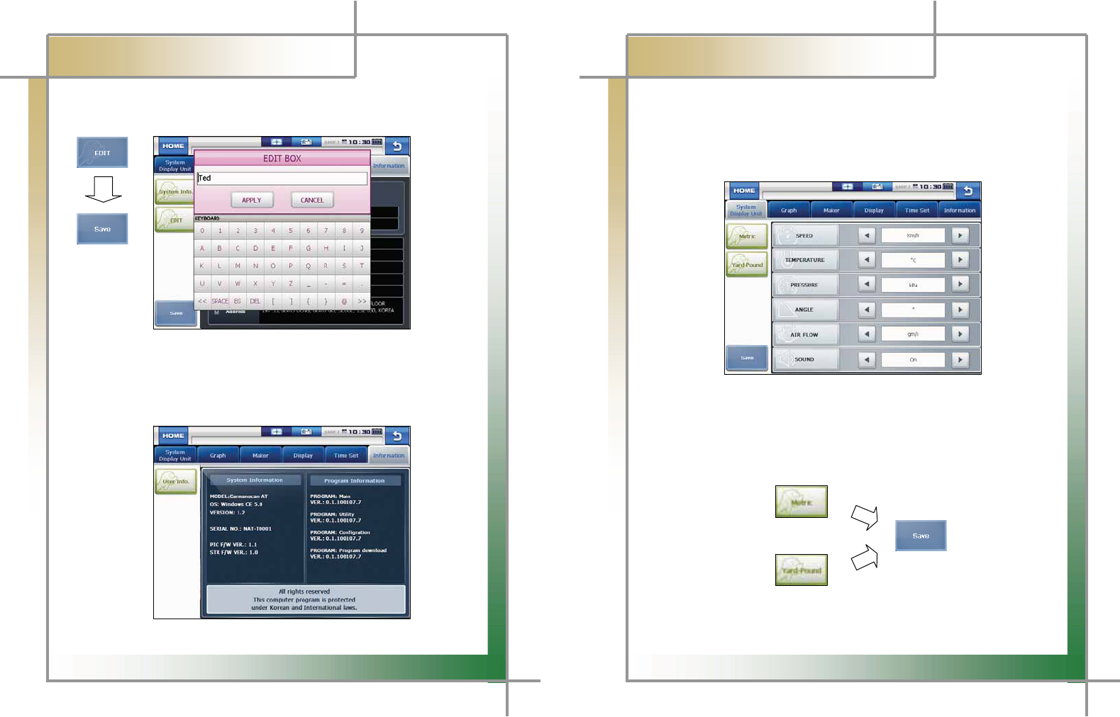
1. Information
In this menu, you can check and enter user and system information.G
G
G
G
G
G
G
G
G
G
G
G
G
G
Figure 3.1 Information > User Info.
G
G
1. Select Information from the Configuration menu.G
2. My Profile is displayed and this information can be edited.G
- When the cursor blinks on the desired text, click the EDIT button.G
G
G
G
G
G
G
G
G
G
G
G
G
27
G
G
CARMAN SCAN NEO User GuideG
G
Chapter 3: Configuration
3. When information is modified after clicking the EDIT button, click the Save button to
save the modified information.G
G
G
G
G
G
G
G
G
G
G
G
G
G
Figure 3.2 Information > Editing “My Profile”G
G
4. Clicking the Information button on the left pane displays the system and program
information.G
GGG
G
G
G
G
G
G
G
G
G
G
G
G
Figure 3.3 Information > System InformationG
28
G
G
CARMAN SCAN NEO User GuideG
G
Chapter 3: Configuration
2. System Display Unit
In this menu, you can change the display unit of data which are sent from a vehicle.G
- The units of various information, such as speed, temperature, pressure, angle, G
air flow and sound, can be checked and modified.G
G
G
G
G
G
G
G
G
G
G
G
G
Figure 3.4 System Display Unit
G
G
1. It is possible to change the display units all at once according to the region that
uses “Metric” or “Yard-Pound” system.G
2. After changing the display unit, click the Save button to save your modification.G
G
G
29
G G G
G
CARMAN SCAN NEO User GuideG
G
Chapter 3: Configuration
G
G
G
- SPEED : You can change between Km/h and MPH.G
- TEMPERATURE : You can change between
and
එ
.G
- PRESSURE : You can change among mbar, kPa, inHg and psi.G
- ANGLE : You can change between ° and %.G
- AIR FLOW : You can change between gm/s and lb/m.G
- SOUND : It can be turned ON or OFF.G
G
30
G
G
CARMAN SCAN NEO User GuideG
G
Chapter 3: Configuration
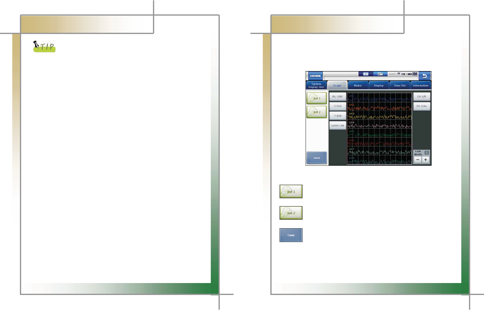
3. Graph
In this menu, you can configure graphs that are displayed for data from sensors.G
- The graph line color, background color and graph line thickness can be set.G
G
G
G
G
G
G
G
G
G
G
G
G
G
G
Figure 3.5 Graph > Init 1G
G
: Pressing this button displays the graph in its initial status as shown in
the figure 3.5.
: Pressing this button displays the graph in its initial status in the white
background.
: When making a change to the setting, click the Save button to save the
modified setting. Then, the graph is displayed in the modified status.
G
G
G
G
G
31
G
G
CARMAN SCAN NEO User GuideG
G
Chapter 3: Configuration
G
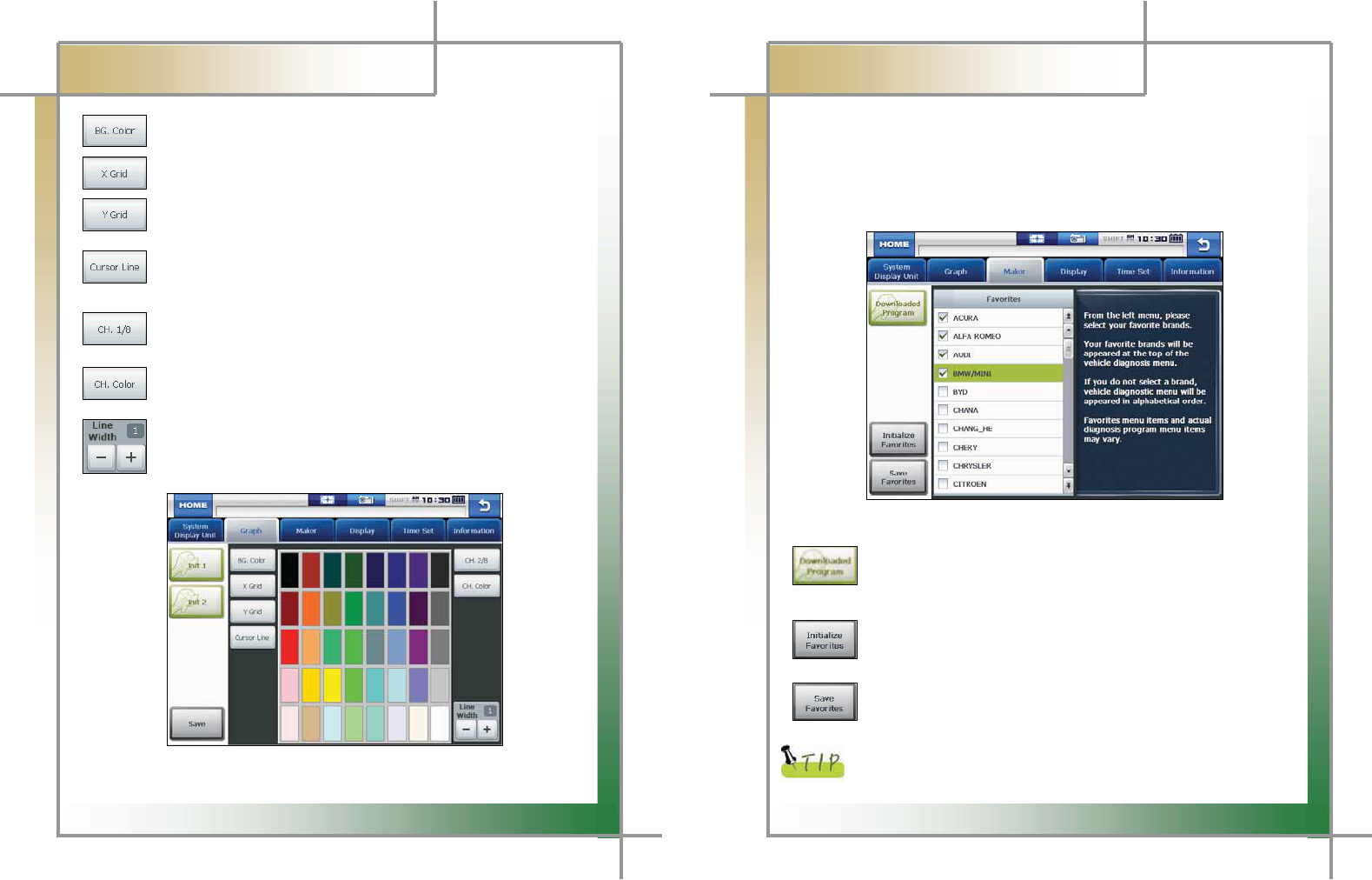
: Press this button to change the background color as desired.
: Press this button to change the color of the vertical line on the grid.
: Press this button to change the color of the horizontal line on the grid.
: Press this button to change the color of the cursor which appears on
which the screen is touched.
: Press this button to change the color of each graph for up to 8 channels.
Up to 8 channels can be displayed on the screen at once.
: Press this button to select the color of the channel graph.
: Press this button to adjust the thickness of the graph line.
G
G
G
G
G
G
G
G
G
G
G
G
G
G
G
Figure 3.6 CH. Color screenG
32
G
G
CARMAN SCAN NEO User GuideG
G
Chapter 3: Configuration
4. Maker
G
It is possible to select your favorite vehicle maker to be displayed on top in the diagnosis
menu.G
- This function can save time to search for the desired vehicle maker whenever
the diagnosis is made.G
G
G
G
G
G
G
G
G
G
G
G
G
G
G
Figure 3.7 Maker
G G
G
G G G G G G G G G G G G G
: Press this button to check the list of the diagnosis programs that are
stored in the internal memory.
You can erase the diagnosis data (version, vehicle maker) by a vehicle maker.G
G
GGGGGGGGGGGGG: Press this button to initialize your favorites.G
GGThe selected favorite items are deselected.G
G
GGGGGGGGGGGGG: Press this button to store the selected favorites.G
GGThis favorites are displayed as icons in order in the diagnosis menu.G
G
The favorite list displayed in this menu can also include makers of
diagnosis programs that are not downloaded.
G
33
G
G
CARMAN SCAN NEO User GuideG
G
Chapter 3: Configuration
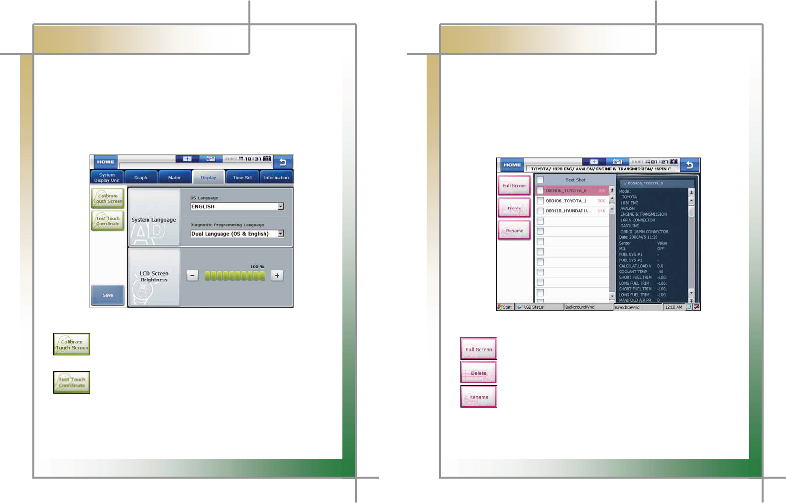
5. Display
G
In this menu, you can align the touch screen coordinates, setup the language and adjust
the LCD brightness.G
- If the touch screen coordinates are not accurate, they can be corrected through the
calibration function. Also, the brightness of the LCD can be adjusted so that the
product can be fit both in dark and bright places.G
Also, the system language can be selected and set by a user.G
G
G
G
G
G
G
G
G
G
G
G
G
G
G
Figure 3.8 DisplayG
G
GGGGGGGGGGGGGGG: Pressing this button displays the touch screen calibration panel.
Press the (+) symbols shown on the screen to correct the coordinates
automatically.G
G
GGGGGGGGGGGGGGG: Press this button to check if the coordinates are calibrated correctly
through the calibration function.
G
System Language : The language of the operating system and diagnostic program can
be set among the languages that are stored in the internal memory.
LCD Screen Brightness : Press the “-” and “+” buttons to adjust the screen brightness.
34
G
G
CARMAN SCAN NEO User GuideG
G
Chapter 4: Utility
In this menu, you can check the flight record, text shots and screen captures and utilizes
the gas analyzer function.G
1. Flight Record
In this menu, you can save the service data for your vehicle for analysis.G
- You can save the desired service data.
- This function is useful when data should be saved to diagnose an intermittent symptom.G
G
G
G
G
G
G
G
G
G
G
G
G
G
G
Figure 4.1 Flight Record
G
G
GGGGGGGGGGGGGGG: Click this button to display the data only selected by the user.G
G
GGGGGGGGGGGGGGG: Click this button to delete the file selected by the user.G
G
GGGGGGGGGGGGGGG: Click this button to rename the file that was temporarily set when saving
the file (only in English).G
G
G
G
G
35
G
G
CARMAN SCAN NEO User GuideG
G
Chapter 4: Utility
G
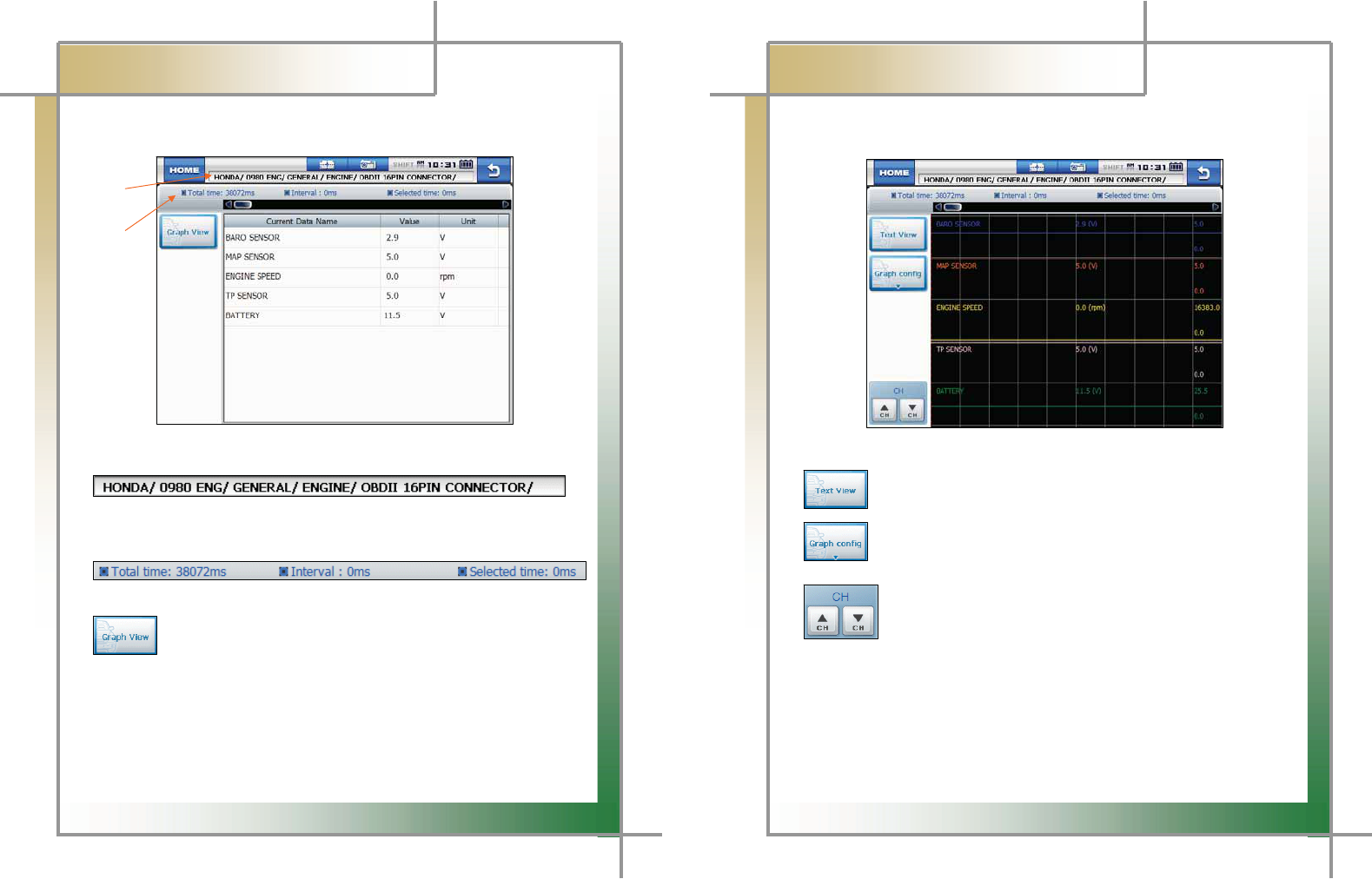
- Text View: Click this button to check the saved data in numbers.G
GGGGGGGGGGGGGGGGGG
G
GGGGGG1
G
GGGGGG2
G
G
G
G
G
G
G
G
G
Figure 4.2 Data_Text ViewG
G
G1.
Maker >> Diagnostic program version >> Language version >> System >>
Diagnostic connector
2.
Total time >> Interval >> Selected time
: Press this button to switch to the graph screen from the text screen.
Ű Total time: The total time of the saved flight record is displayed.
Ű Interval: This indicates the time from the initial clicked position of the bar on top to
the point that the bar is dragged and released.
Ű Selected time: This indicates the time of the currently clicked position of the bar in
the total time.
G
36
G
G
CARMAN SCAN NEO User GuideG
G
Chapter 4: UtilityG
G
-GGraph View: Click this button to switch to the graph screen for tendency analysis.G
G
G
G
G
G
G
G
G
G
G
G
G
G
G
Figure 4.3 Data_Text View
G
G
GGGGGGGGGGGGGGG: Press this button to switch the graph screen to the text screen.G
G
GGGGGGGGGGGGGGG: Press this button to configure the displayed graph.G
G
G
GGGGGGGGGGGGGGGG: In the graph screen, up to 8 current data are displayed at once.
If more than 8 current data are saved, click the channel Ÿ and ź keys
to scroll the current data.
GGGGGGGGGGGGGGGG
G
GGGGGGGGGGGGGGGGG
G
37
G
G
CARMAN SCAN NEO User GuideG
G
Chapter 4: UtilityG
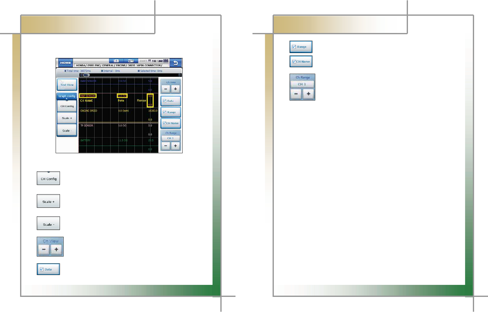
- Graph config: Press this button to set the channel, current value and max./min.
values of graphsG
G
G
G
G
G
G
G
G
G
G
G
G
G
Figure 4.4 Data_Graph config (CH Config)G
G
GGGGGGGGGGGGGGGGG : Clicking this button displays the panel on the right to setup each
displayed graph by a channel.G
G
GGGGGGGGGGGGGGGGG : Pressing this button extends the horizontal axis on the grid for more
precise graph analysis.G
GGGGGGGG
: Pressing this button shortens the horizontal axis on the grid to
display more data on the screen at once.G
G
GGGGGGGGGGGGGGGGGG: 5 current data are displayed on the screen at once by default.
The number of data displayed on the screen can be set from 1 to 8.G
G
G
GGGGGGGGGGGGGGGGG : Press this button to show or hide the current value of the sensor.G
G
38
G
G
CARMAN SCAN NEO User GuideG
G
Chapter 4: UtilityG
G
GGGGGGGGGGGGGGGGG : Press this button to show or hide the maximum and minimum
values for each sensor on the right side of the screen.G
GGGGGGGGGGGGGGGGG : Press this button to show or hide the sensor names.G
G
G
GGGGGGGGGGGGGGGGGG: Press these buttons, you can increase or decrease the maximum
value for each channel to increase or decrease the graph values.G
G
G
G
G
G
G
G
G
G
G
G
G
G
G
G
G
G
G
G
G
G
G
G
G
G
G
39
G
G
CARMAN SCAN NEO User GuideG
G
Chapter 4: UtilityG
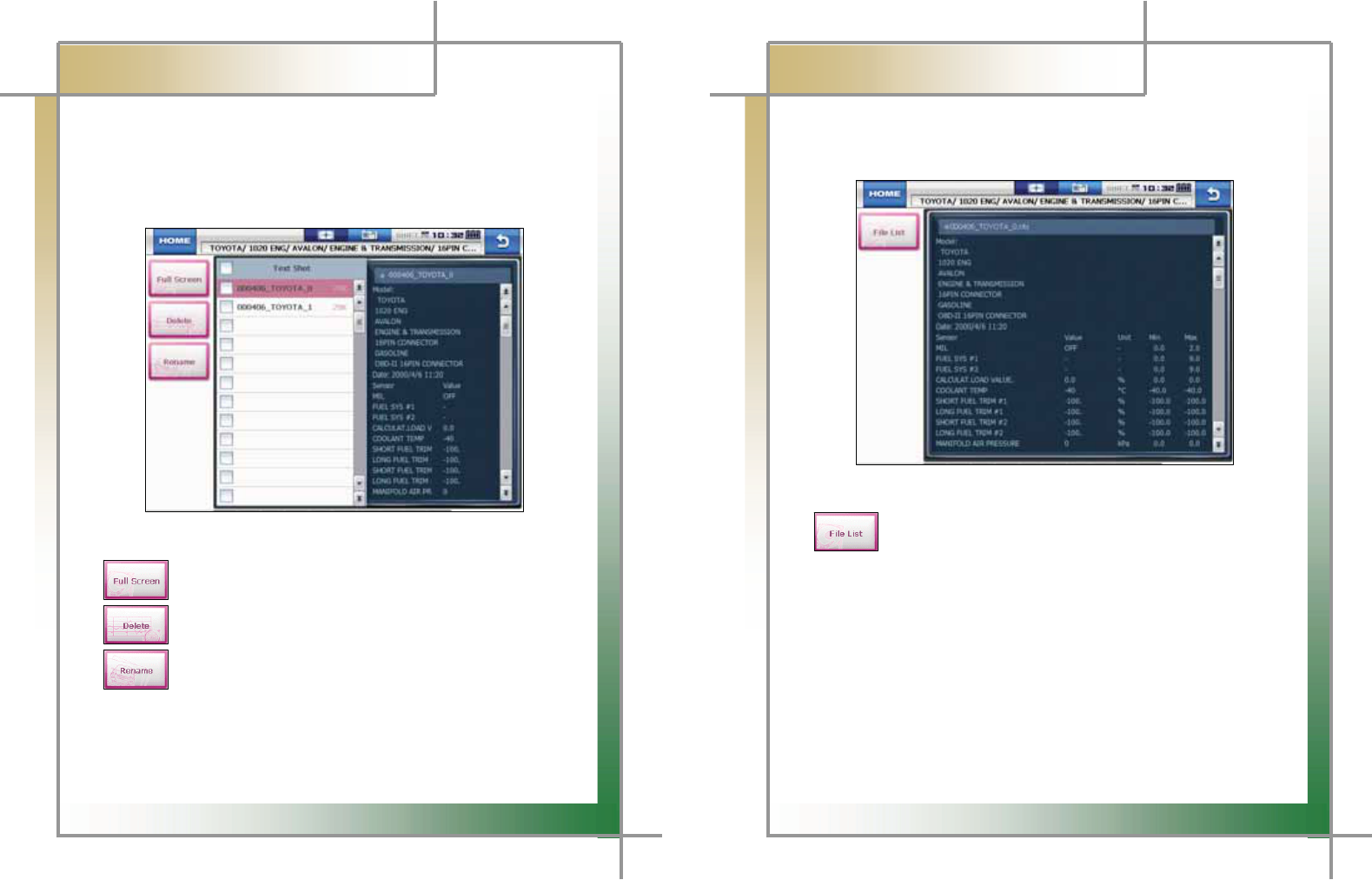
2. Text Shot
This function is to save all values of the current data for the selected moment from a
system being diagnosed. This is used to save data at a certain moment and analyze them.G
- As all data can be saved at once, you can diagnose your vehicle conveniently.G
G
G
G
G
G
G
G
G
G
G
G
G
G
G
G
Figure 4.5 Text Shot > Item selectionG
G
GGGGGGGGGGGGGGGGG: Press this button to display all saved data for the selected item(s).G
G
GGGGGGGGGGGGGGGGG: Press this button to delete the selected item.G
G
GGGGGGGGGGGGGGGGG: Press this button to rename the selected file from the temporarily set
name.G
G
G
G
G
G
40
G
G
CARMAN SCAN NEO User GuideG
G
Chapter 4: UtilityG
G
GGGG-GFull Screen: As all current data are saved for the selected system, you can utilize
the full screen function to check the vehicle condition conveniently.G
G
G
G
G
G
G
G
G
G
G
G
G
G
G
G
Figure 4.6 Text Shot > Full ScreenG
G
GGGGGGGGGGGGGGGGG: Press this button to return to the Text Shot list.G
G
G
G
G
G
G
G
G
G
G
G
G
41
G
G
CARMAN SCAN NEO User GuideG
G
Chapter 4: UtilityG
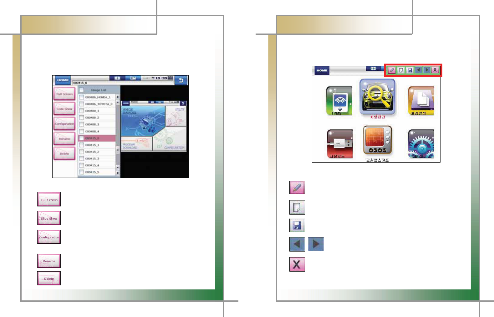
3. Screen Capture
You can take a screen capture and save it when necessary.G
- As you can take a screen capture with a simple action, this function is very
convenient and useful for your diagnosis.G
G
G
G
G
G
G
G
G
G
G
G
G
G
G
Figure 4.7 Screen CaptureG
G
GGGGGGGGGGGGGGGG: Press this button to show the saved files on a full screen.G
G
GGGGGGGGGGGGGGGG: Select several files and press this button to display them in a slide
show.G
G
GGGGGGGGGGGGGGGG: Press this button to set the number of repetition and the display time
of each file in a slide show and to adjust the color and thickness of the
red marker in a full screen.G
G
GGGGGGGGGGGGGGGG: Press this button to rename the file.G
G
GGGGGGGGGGGGGGGG: Press this button to delete a file.G
G
42
G
G
CARMAN SCAN NEO User GuideG
G
Chapter 4: UtilityG
G
- Full Screen: The red marker function can be used in the full screen. You can make
or edit a note onto a saved screen capture.G
G
G
G
G
G
G
G
G
G
G
G
G
G
G
G
Figure 4.8 Full Screen > Red MarkerG
G
GGGGGGGGGGG: Press this button to activate the red marker function. Then, click on the
screen and drag it to make a mark.G
GGGGGGGGG
GGGGGGGGGGG: Press this button to edit the contents written with the red marker function.G
G
GGGGGGGGGGG: Press this button to save the written contents.G
G
GGGGGGGGGGGGGGGGGGG: If several data are selected in the Image list (Figure 4.7), you can
switch between images and use the red marker function.G
G
: Press this button to deactivate the function.
G
G
43
G
G
CARMAN SCAN NEO User GuideG
G
Chapter 4: UtilityG
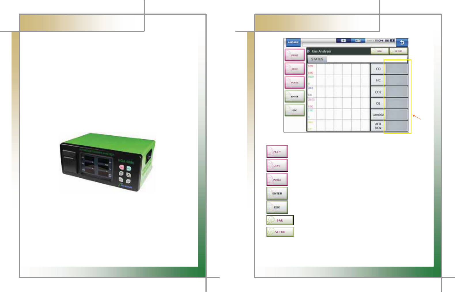
4. Gas Analyzer
CARMAN SCAN NEO can measure and analyzer the emitted gas with Gas analyzer.
How to connect
G
G
1. Preparation
G
NGA 6000 module, RS232C cable and CARMAN SCAN NEOG
G
2. Connection
G
- Connect the NGA 6000 module to CARMAN SCAN NEO with the RS232C cable.
- Click on the Gas Analyzer button.
G
G
G
G
G
G
G
G
G
G
G
Figure 4.9 NGA 6000 GAS ANALYZERG
G
G
44
G
G
CARMAN SCAN NEO User GuideG
G
Chapter 4: UtilityG
G
G
G
G
G
G
G
G
G
G
G
G
GGGGGGGGGGGGGGGGGGGGGGGGGGGGGGGGGGGGGGGGGGGGGGGGGGGGGGGGGGGGGGGGGGGGGGGGGGGGGGGGGGGG
ཛG
G
G
Figure 4.9 Gas AnalyzerG
G
GGGGGGGGGGGGGGG : Press this button to print the test result.G
G
: Press this button to set the measurement to 0.G
G
GGGGGGGGGGGG : Press this button to purge the remaining gas from the measurement
probe with clean air.G
G
: Press this button to start the function (measurement).G
G
GGGGGGGGGGGGGGGG: Press this button to cancel the function and return to the previous screen.G
G
GGGGGGGGGGGGGGGGG: Press this button to switch to the bar graph.
G
GGGGGGGGGGGGGGGGG: Press this button to setup the test items and criteria.G
G
Gྙ
ྙ
GIf the measurement is over the value specified in the SETUP menu, it is displayed in
red.G
G
45
G
G
CARMAN SCAN NEO User GuideG
G
Chapter 5: TPMS
G
G
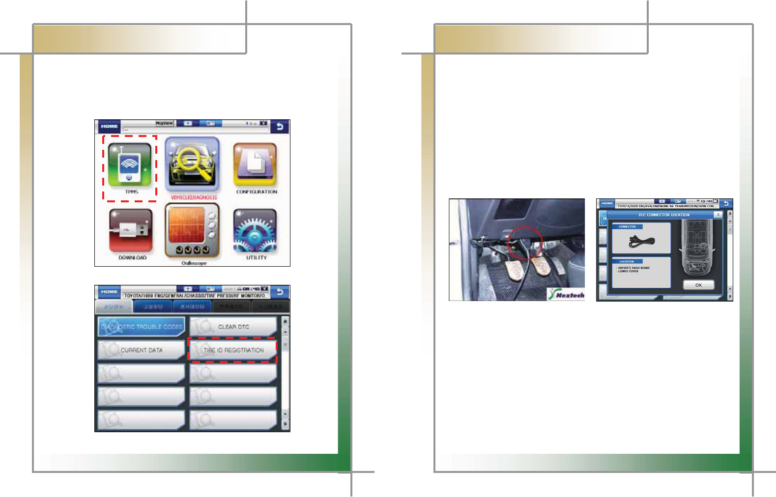
1. TPMS
TPMS should be supported with TPMS module which is optional.G
Using TPMS product function please. Register ID after the replacement and repair of tire or
wheel.G(But, it can be used with only TPMS system.)G
G
G
G
G
G
G
G
G
G
G
GGGGGGGGGGGGGGGGGGGGGGGGGGGGGGGGGGGGGGGGGGGGGGGGGGGGGGGGGGGGGGGGGGGGGGGGGGGGGGG
G
G
G
Figure 5.1 TPMS
.G
G
G
G
G
G
G
G
G
G
G
G
Figure 5.2 TPMS ID REGISTRATION
46
G
G
CARMAN SCAN NEO User GuideG
G
Chapter 6: Diagnosis Menu
1. How To Connect Self-Diagnostic Connector and Select
Diagnosis Program
(for Korean, Japanese and European vehicles)
1. Locate the diagnostic connector in the vehicle.G
- Most vehicles released after year 2002 conform to the OBD-II Protocol and
have OBD-II diagnostic connectors.G
- Most OBD-II vehicles have their diagnostic connectors on the section over the
brake pedal under the steering wheel.G(Figure 6.1)
G
- If an additional adaptor is required, the scanner display shows the type of the
necessary adaptor and the location of the diagnostic connector. (Figure 6.2)G
G
G
G
G
G
G
G
G
G
G
Figure 6.1 Location of OBD-II Figure 6.2 Adapter and DLC
diagnostic connector location guide screen
G
G
G
2. Use the diagnosis cable to connect the vehicle's diagnostic connector and
CARMAN SCAN NEO.G
3. Turn on CARMAN SCAN NEO.G
- If power is not feed through the diagnostic connector and the CARMAN SCAN
NEO battery is not fully charged, you need to connect an additional power
supply (vehicle battery or cigarette lighter power cable, etc).G
4. Select the [VEHICLE DIAGNOSIS] menu.G
G
G
47
G
G
CARMAN SCAN NEO User GuideG
G
Chapter 6: Diagnosis Menu
G
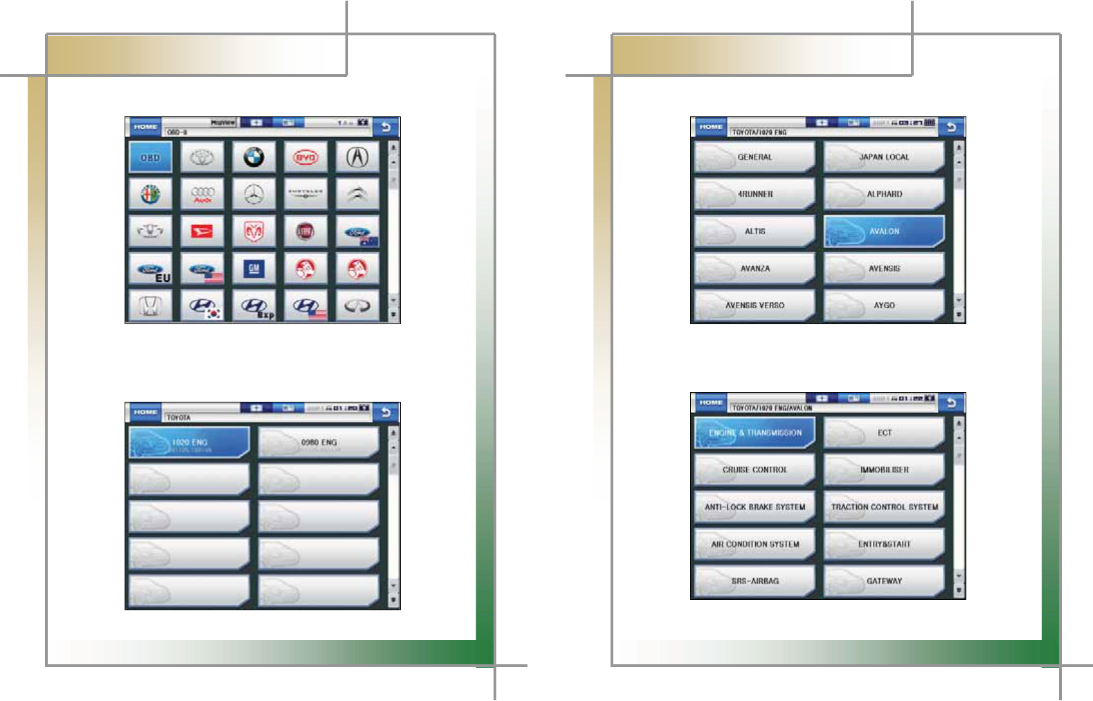
5. Select the maker of the vehicle to be diagnose.G
G
G
G
G
G
G
G
G
G
G
G
G
G
Figure 6.3 Vehicle maker selection
G
G
6. If there are several diagnostic data versions in the internal memory of G
CARMAN SCAN NEO, select the desired diagnosis data version.G
G
G
G
G
G
G
G
G
G
G
G
G
G
Figure 6.4 Diagnosis program version selection
48
G
G
CARMAN SCAN NEO User GuideG
G
Chapter 6: Diagnosis Menu
G
7. Select the vehicle model to be diagnose.G
G
G
G
G
G
G
G
G
G
G
G
G
G
Figure 6.5 Vehicle model selection
G
8. Select the system to be diagnose.G
G
G
G
G
G
G
G
G
G
G
G
G
G
Figure 6.6 System selection
G
49
G
G
CARMAN SCAN NEO User GuideG
G
Chapter 7: Vehicle Diagnosis
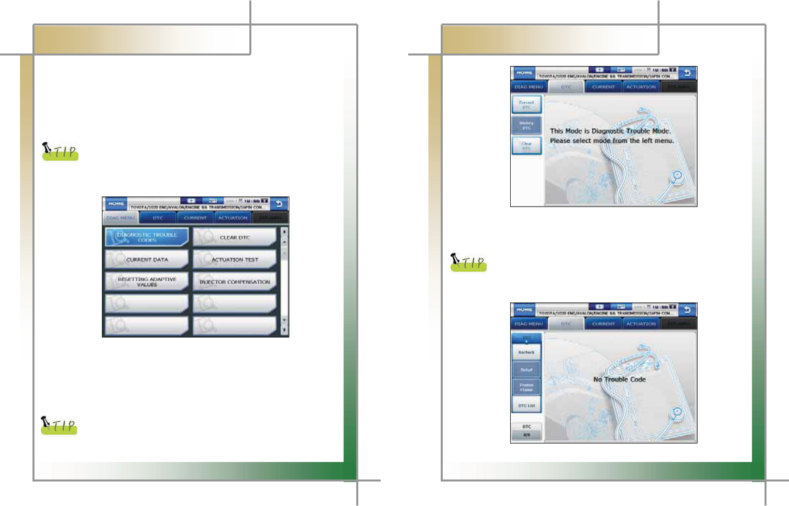
1. Diagnostic Trouble Codes
G- In this menu, it is possible to check for any malfunction of the selected vehicle system
through the communication with the ECU in the vehicle. As CARMAN SCAN NEO
displays DTCs (Diagnostic Trouble Codes), you can easily check where malfunction
occurs.GAlso, the description for DTCs is displayed as well to help you service your
vehicle.G
G
In order to check for DTCs, you need to connect CARMAN SCAN NEO
to the vehicle diagnostic connector correctly. Refer to Chapter 6
“Diagnosis Menu” for correct connection. Also, recheck the
specifications, such as the vehicle maker, vehicle model, displacement,
etc.
G
G
G
G
G
G
G
G
G
G
G
G
Figure 7.1 DTC selectionG
NOTE) The menu for DTC selection, shown in the figure 7.1, can differ by vehicle
makers and models.G
1. When selecting the correct vehicle model and system from the menu and communication
with the vehicle is properly established, the menu appears as the figure 7.1.
Select DIAGNOSTIC TROUBLE CODES and press the ENTER key.G
G
If the message indicating a communication error is displayed instead
of the menu like the figure 7.1 or communication cannot be established,
check the vehicle condition and the connection status of the diagnostic
50
G
G
CARMAN SCAN NEO User GuideG
G
Chapter 7: Vehicle DiagnosisG
G
G
G
G
G
G
G
G
G
G
G
G
G
Figure 7.2 DTC 1
G
G
2. The DTC search screen appears. Now, you can check current and old DTCs and
erase them.G
Old DTCs are not activated unless there is no corresponding fault history.
Diagnostic Trouble Codes detected only when the text shot can be
saved.
3. Press the Current DTC button to check if there is any current DTC.G
G
G
G
G
G
G
G
G
G
G
G
G
Figure 7.3 DTC 2
G G G G G G G G G G G G G G G G G G G G G
G
51
G
G
CARMAN SCAN NEO User GuideG
G
Chapter 7: Vehicle DiagnosisG
G
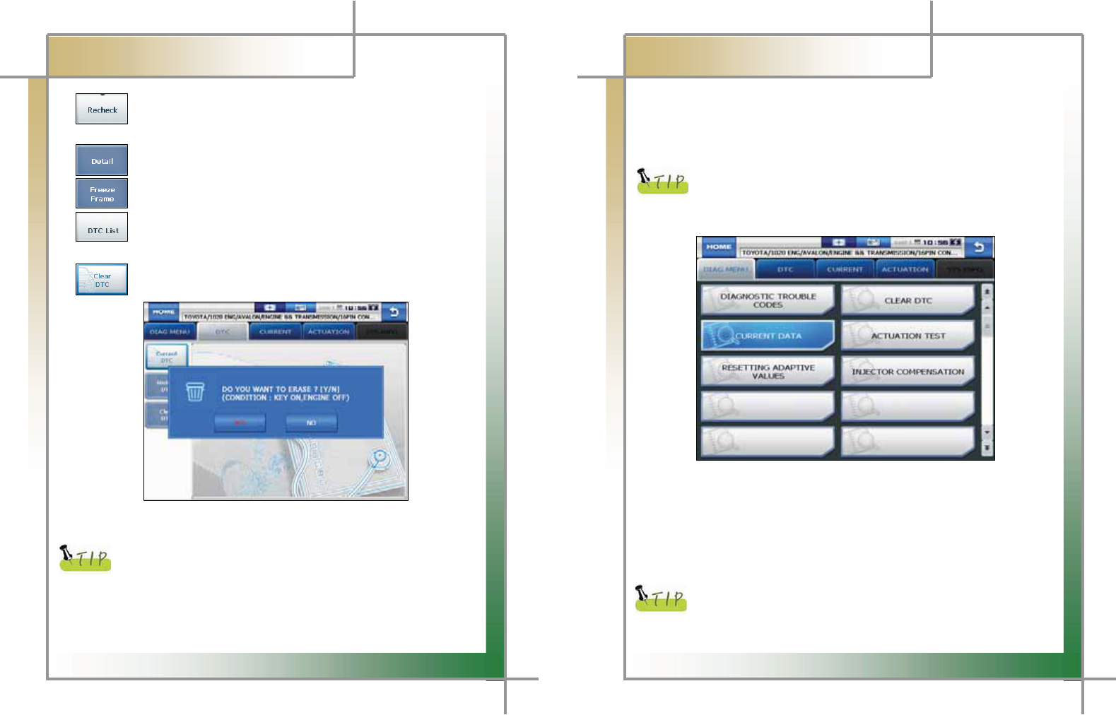
GGGGGGGGGGGGGG: Press this button to check for DTCs again.G
GG G G The module checks the ECU information again for DTCs.G
G
GGGGGGGGGGGGGG: Press this button to display detailed information for DTCs.G
G
GGGGGGGGGGGGGG: Press this button to check Freeze Frame data for malfunction.G
G
GGGGGGGGGGGGGG: Press this button to check the DTC list for malfunction if the vehicle is
equipped with MIL.G
GGGGGGGGGGGGGG
: Press this button to clear DTC.G
G
G
G
G
G
G
G
G
G
G
G
G
G
Figure 7.4 DTC 3G
G
There are current and old DTCs. When trying to clear old DTCs, they
are cleared immediately and they are not set again. However, when
trying to clear current DTCs, they are cleared for a short period of time
but they are activated again. In this case, clear DTCs again after
checking and repairing malfunction parts for the corresponding DTCs.G
G
52
G
G
CARMAN SCAN NEO User GuideG
G
Chapter 7: Vehicle DiagnosisG
2. Current Data
-GGIn the CURRENT DATA menu, the module can communicate with the vehicle ECU
to check data and control values of each sensor of the selected system and to check
conditions of various switches and actuators.
G
It is important to select the vehicle specifications correctly for accurate
sensor data measurement. Make sure to set the vehicle displacement,
manufactured year, fuel, etc. correctly.G
The current data list can differ even with the same vehicle models.
G
G
G
G
G
G
G
G
G
G
G
G
G
G
G
Figure 7.5 Current data item selection
G
NOTE) The menu for current data selection, shown in the figure 7.5, can differ by vehicle
makers and models.G
1. When selecting the correct vehicle model and system from the menu and communication
with the vehicle is properly established, the menu appears as the figure 7.5.G
Select CURRENT DATA and press the ENTER key.G
G
If the message indicating a communication error is displayed instead
of the menu like the figure 7.5 or communication cannot be established,
check the vehicle condition and the connection status of the diagnostic
connector again.
53
GG
G
CARMAN SCAN NEO User GuideG
G
Chapter 7: Vehicle DiagnosisG
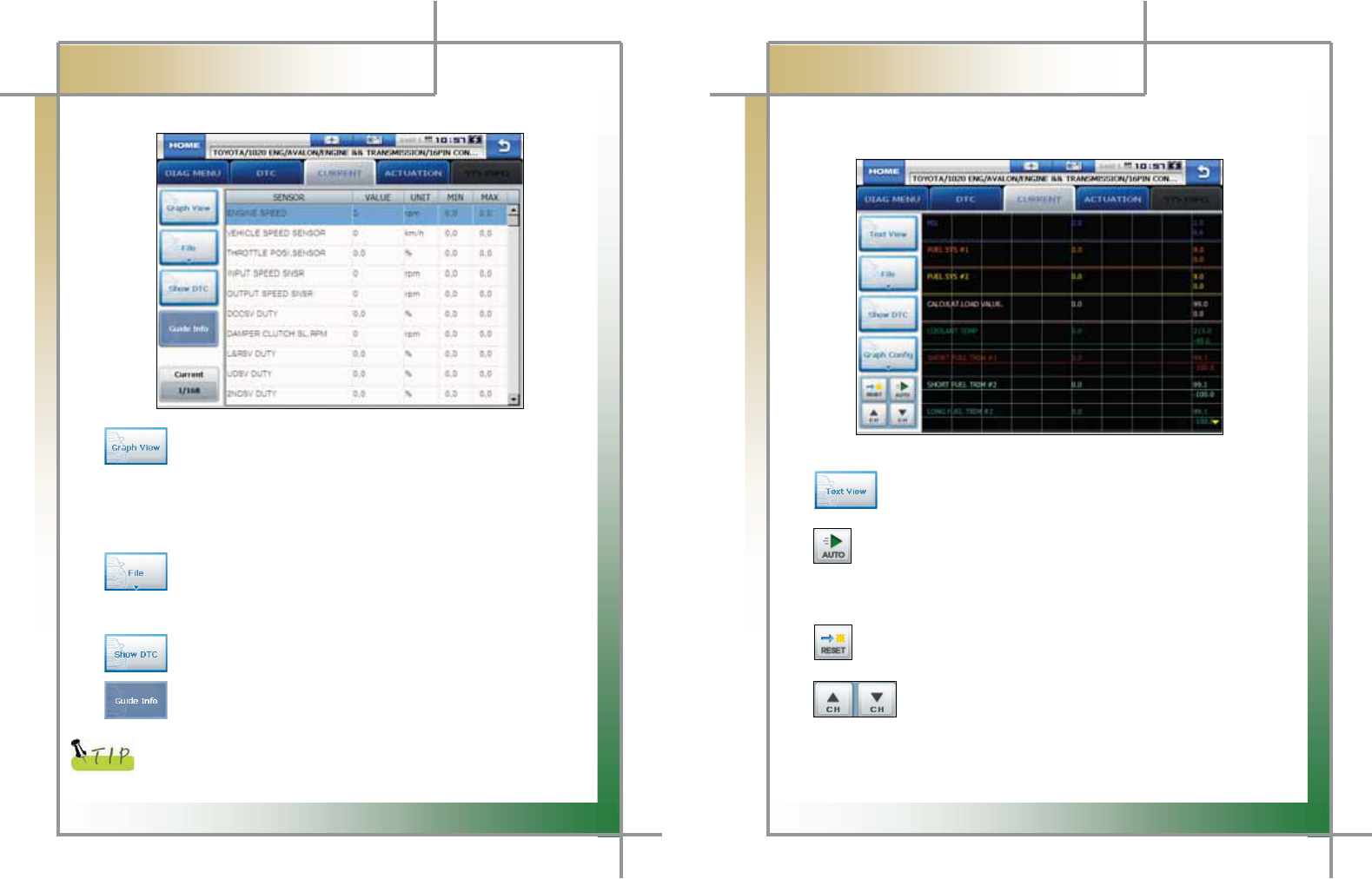
2. The current data list is displayed as shown in the figure 7.6.
G
G
G
G
G
G
G
G
G
G
G
G
G
G
G
Figure 7.6 CURRENT DATA 1
G
GGGGGGGGGGGGGGGG: Press this button to check current data in graphs.G
- It is helpful to convert the current vehicle data to graphs for tendency analysis.
(Up to 30 items can be selected while up to 8 graphs can be displayed at a time.)
- To convert current data to graphs, such data are need to be fixed. Then, only
these fixed data change.G
G
GGGGGGG: Press this button to save sensor data or check the saved files.G
- Data are stored in the internal memory and they can be stored synchronized with
your PC.G
G
GGGGGGG: Press this button to display DTCs at once.G
G
GGGGGGG: If the selected system has help information, this button is activated.
Then, press this button to display information.G
G
When fixing only certain items, values of only these items change.
Therefore, the data change measurement is performed faster and more
precise diagnosis can be achieved.
G
54
G
G
CARMAN SCAN NEO User GuideG
G
Chapter 7: Vehicle DiagnosisG
G G G G G
G
- Graph View: This function is to check current data in graph forms for tendency
analysis.G
GGGGGG
GGGGGGG
G
G
G
G
G
G
G
G
G
G
G
G
Figure 7.7 CURRENT 2G
G
GGGGGGGGGG: Press this button to switch to the text view mode.G
G
GGGGGG: Press this button to switch to the graph view mode and display the maximum
and minimum values of the measured sensor data.G
- In the normal mode, the maximum and minimum values of each sensor are
programmed into the ECU and these programmed values are displayed.G
G
: Press this button to deactivate the automatic mode. Then, the maximum
and minimum values are displayed in the normal mode.G
G
G
GGGGGGGGGGGGG: In the graph view mode, up to 8 current data can be displayed at a
time. If the number of sensor data displayed on the screen at a time
is set to less than 8, the remaining current data are displayed in the
list on the bottom. (Adjust the number with the up/down buttons.)G
G
G
55
GGG
G
CARMAN SCAN NEO User GuideG
G
Chapter 7: Vehicle DiagnosisG
G G G G G G
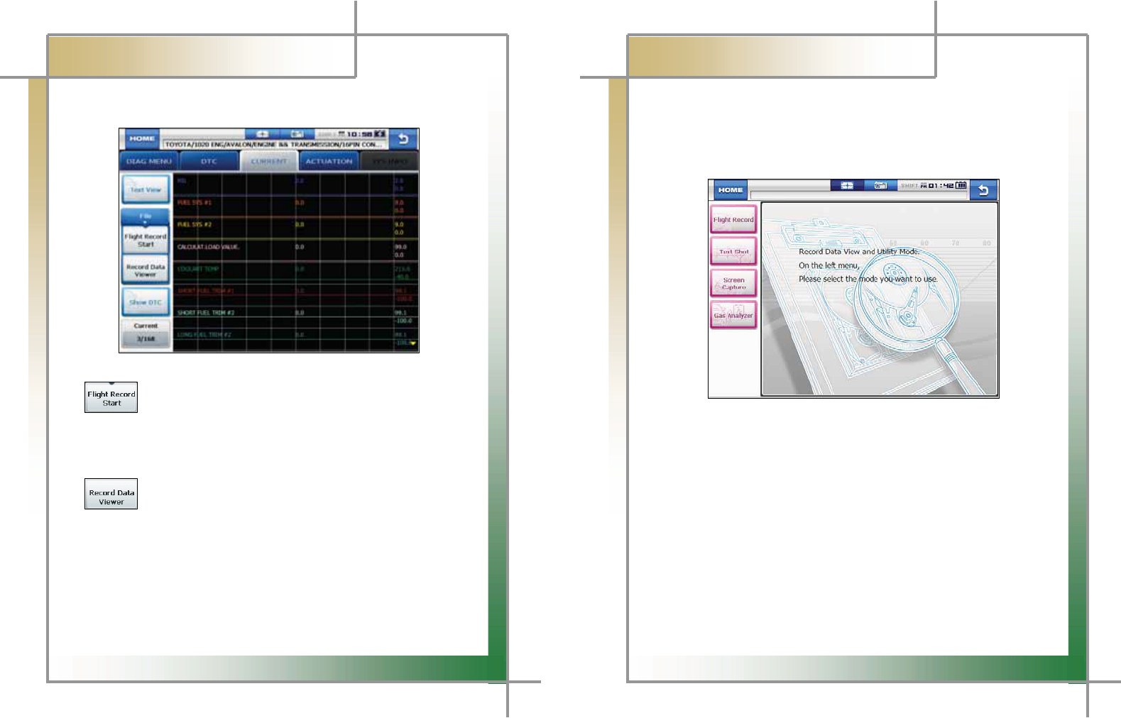
- File: Press this button to save data or check the saved data.G
G
G
G
G
G
G
G
G
G
G
G
G
G
G
Figure 7.8 Flight Record DataG
G
GGGGGGGGGGGGGGGGG: Press this button to start to record the selected sensor data.G
- The data can be recorded for up to 1 hour and the recording time can vary
depending on the number of the selected current data.G
(When the recording operation is performed for 1 hour, it stops automatically.)G
G
GGGGGGGGGGGGGGGGG: Press this button to check or search for the stored file(s)
or retrieve and display data as necessary.G
G
G
G
G
G
G
G
G
56
G
G
CARMAN SCAN NEO User GuideG
G
Chapter 7: Vehicle DiagnosisG
G
1. The screen displays the Record Data menu pane where you can check the
saved data through the flight record list.G
2. For the flight record, text shot, screen capture and gas analyzer functions, refer
to Chapter 4. Record Data.
G
G
G
G
G
GGGGGGGGGGGGGGGGGGG
G
G
G
G
G
G
G
G
G
Figure 7.9 Record Data ViewerG
G
G
G
G
G
G
G
G
G
G
G
G
G
57
G
G
CARMAN SCAN NEO User GuideG
G
Chapter 7: Vehicle DiagnosisG
G
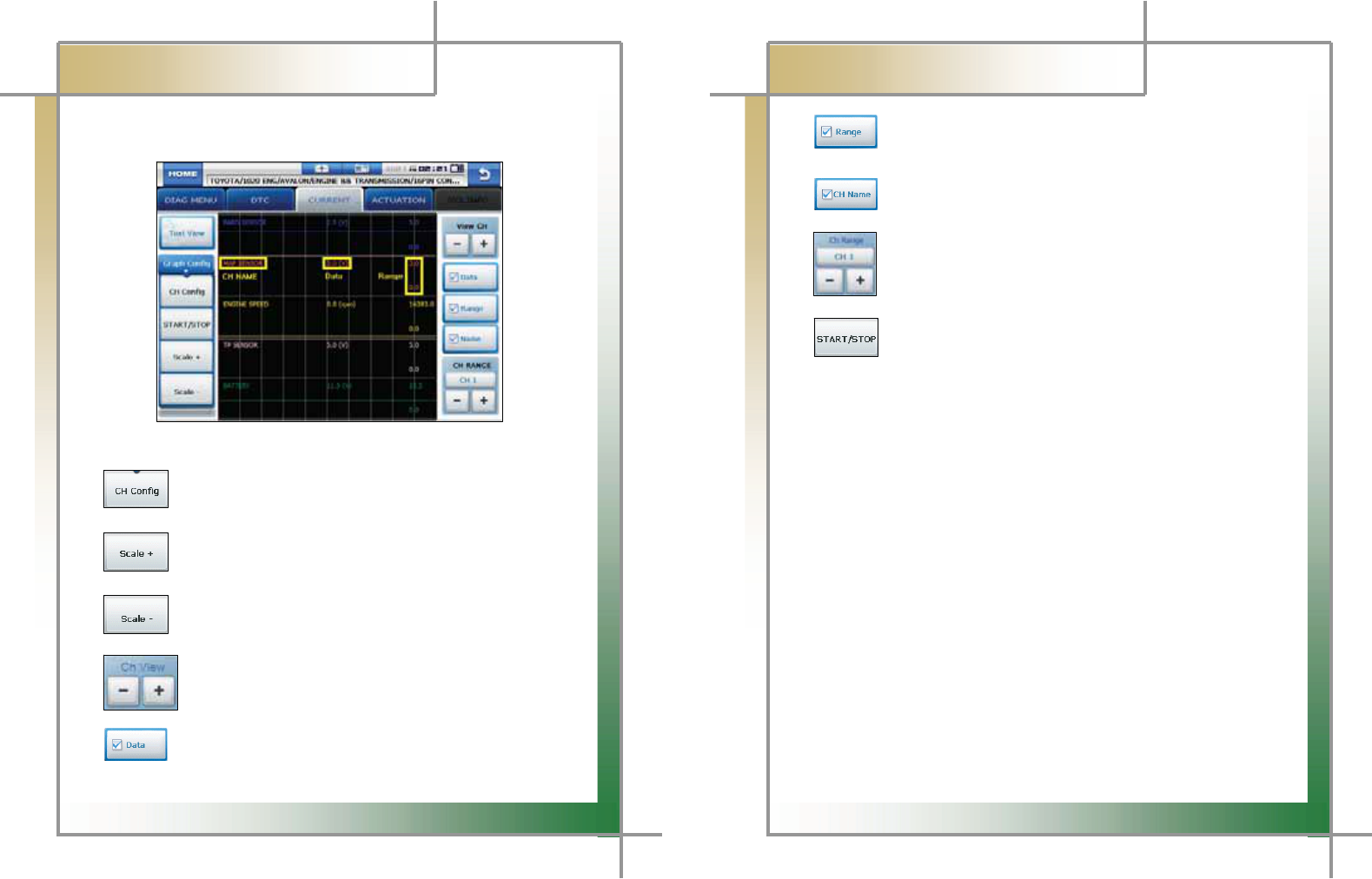
- Graph Config: Press this button to set the channel, current value and max./min.
values of graphs.G
G
G
G
G
G
G
G
G
G
G
G
G
G
Figure 7.10 Graph ConfigG
G
GGGGGGGGGGGGGGGGG : Press this button displays the panel on the right to setup each
displayed graph by a channel.G
G
GGGGGGGGGGGGGGGGG : Press this button extends the horizontal axis on the grid for more
precise graph analysis.G
GGGGGGGG
GGGGGGGGGGGGGGGGG : Press this button shortens the horizontal axis on the grid for more
Precise graph analysis.G
G
GGGGGGGGGGGGGGGGGG: 5 current data are displayed on the screen at once by default.
The number of data displayed on the screen can be set from 1 to 8.G
G
GGG : Press this button to show or hide the current value of the sensor.G
G
G
58
G
G
CARMAN SCAN NEO User GuideG
G
Chapter 7: Vehicle DiagnosisG
G
GGGGGGGGGGGGGGGG : Press this button to show or hide the max and min values
for each sensor on the right side of the screen.G
G
GGGGGGGGGGGGGGGG : Press this button to show or hide the sensor names.G
G
: Press this button to increase/decrease the max value range to zoom in
and out the displayed graphs.G
G
: Press this button to stop the screen while checking current data. Press
this button again starts the screen.G
G
G
G
G
G
G
G
G
G
G
G
G
G
G
G
G
G
G
G
G
G
59
G
G
CARMAN SCAN NEO User GuideG
G
Chapter 7: Vehicle DiagnosisG
G
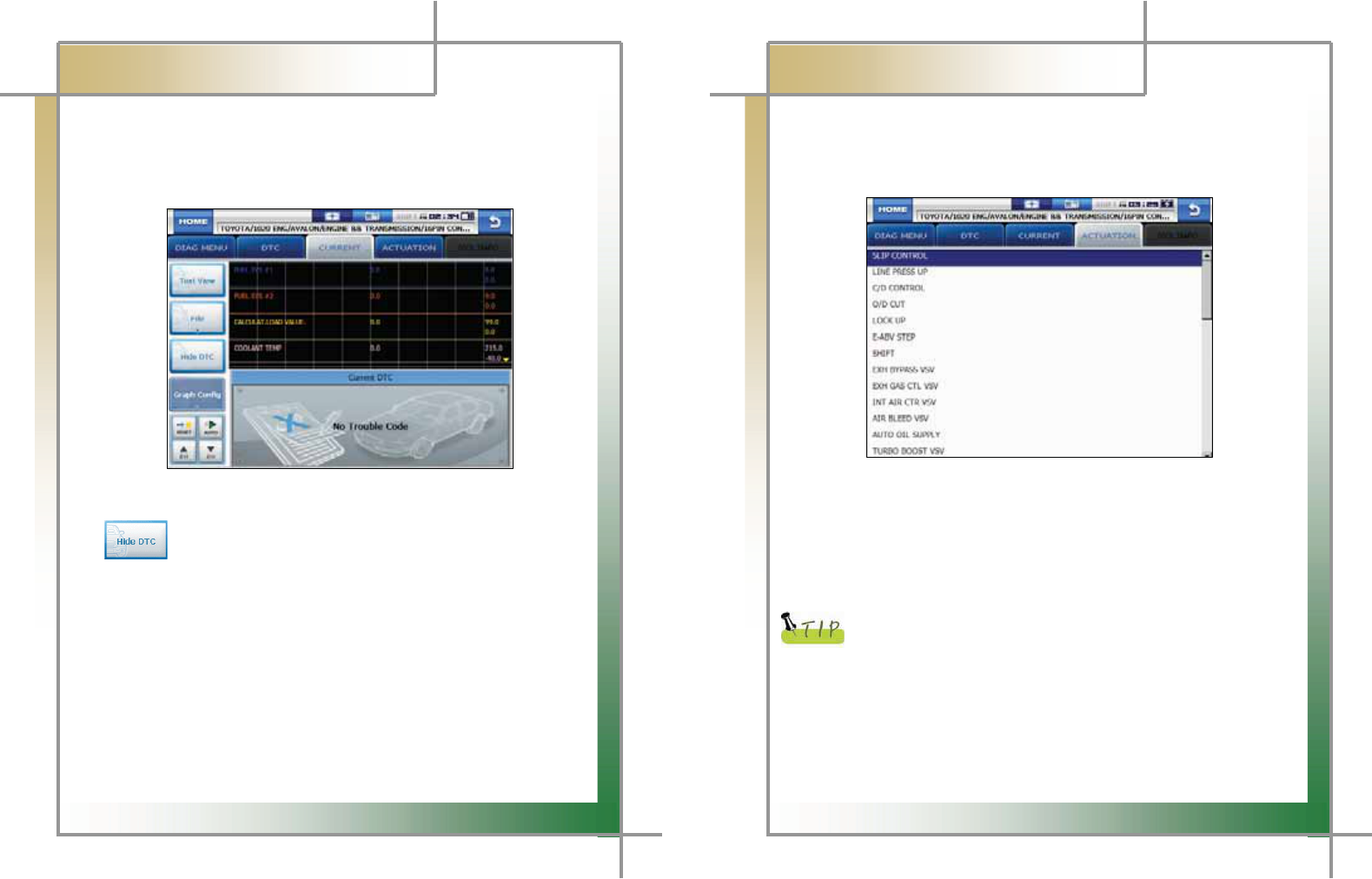
GGGGG-GShow DTC: The upper half of the screen displays the current data while the lower
half of the screen displays the DTC list.G
If there is any DTC, the corresponding sensor data can be checked
for comparison.G
G
G
G
G
G
G
G
G
G
G
G
G
G
Figure7.11 Current data & DTCG
G
GGGGGGGGGGGGGGGGG: Press this button to exit the dual display mode and return to the
Record Data Viewer.G
G
G
G
G
G
G
G
G
G
G
G
60
G
G
CARMAN SCAN NEO User GuideG
G
Chapter 7: Vehicle DiagnosisG
3. Actuation
- In this menu, you can start and stop actuators and switches forcibly to diagnose them.G
- The actuation function is available depending on vehicle makers and models.G
GGGG
G
G
G
G
G
G
G
G
G
G
G
G
Figure 7.12 ACTUATION > Selection
G
G
1. When selecting the correct vehicle model and system from the menu and
communication with the vehicle is properly established, the menu appears as the
figure 7.12.G
Select an item to actuate.G
G
If the message indicating a communication error is displayed instead
of the menu like the figure 7.12 or communication cannot be established,
check the vehicle condition and the connection status of the diagnostic
connector again.
G
G
2. The screen Figure 7.13 ACTUATION > 1 appears.G
G
G
G
61
G
G
CARMAN SCAN NEO User GuideG
G
Chapter 7: Vehicle DiagnosisG
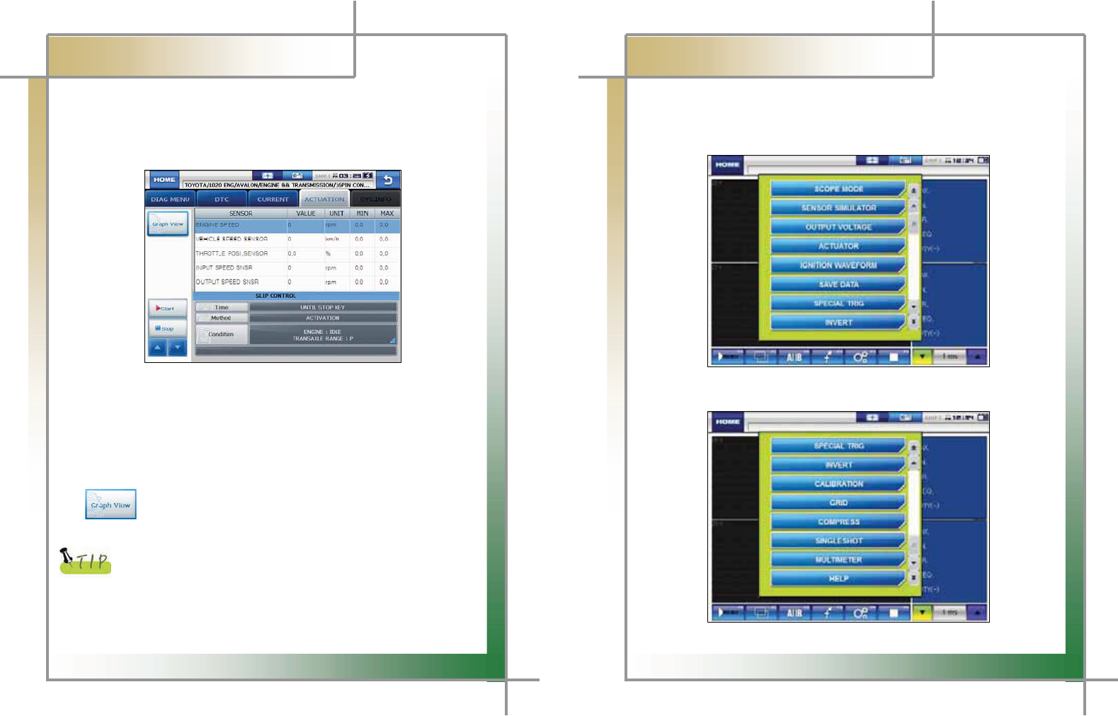
3. Press the Start button starts the actuation function.
- Before starting actuation, make sure to check the operating condition to
inspect the system in the proper condition.
- The actuation time differs by the actuated items.
Figure 7.13 ACTUATION > 1
4. Press the Stop button stops the actuation function.
- Press this button to stop the actuation function during diagnosis.
- Press the ESC button on the main module or the arrow button on the right
top corner of the screen also stops the actuation function.
: Press this button to switch from the text view mode to the graph view
mode.
The actuation result is judged by noise from the running actuator or
switch and vehicle RPM change.
Therefore, it is recommended to perform the actuation test in a quiet
area and use current data values as a reference.
62
G
G
CARMAN SCAN NEO User GuideG
G
Chapter 8: OSCILLOSCOPE
1. Main Menu
The user can choose from 2 channel scope modes and ignition waveform measurement
mode. (Guidelines in the menu may vary according to function improvementUP
G
G
G
G
G
G
G
G
G
G
GGG
G G G
G
Fig. 8.1 Oscilloscope Main Menu
Fig. 8.2 Oscilloscope Main Menu
63
G
G
CARMAN SCAN NEO User GuideG
G
Chapter 8: OSCILLOSCOPE
2. Scope environment setup
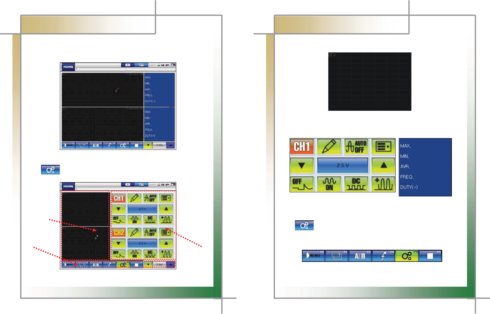
When [scope] is selected in [Fig. 8.2], the screen in [Fig. 8.3] appears
Fig. 8.3 Measurement main screen
When icon is clicked in [Fig. 8.3], the screen in [Fig. 8.4] appears
ྙ
ྛ
ྚ
Fig. 8.3 Measurement main screen
ྛ
Fig. 8.4 Measurement environment setup screen
64
G
G
CARMAN SCAN NEO User GuideG
G
Chapter 8: OSCILLOSCOPE
1) Waveform display window
Fig. 8.5 Waveform display window
ත It consists of 4 channels in the middle of the screen and displays waveforms.
2) Environment setup / Measured value window
Fig. 8.6 Environment setup / Measured value window
ත It is consisted of 4 channels on the right side of the screen, which circulates
by icon..
3) Menu window
Fig. 8.7 Menu window
ත Area at the bottom of the screen, where the user can choose from various scope
65
G
G
CARMAN SCAN NEO User GuideG
G
Chapter 8: OSCILLOSCOPE
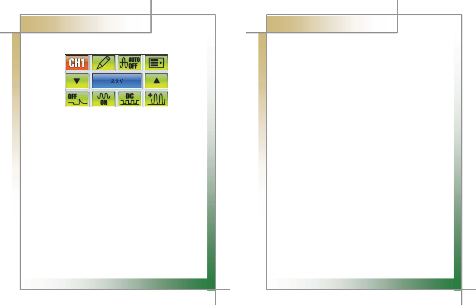
3. Description of scope environment setup icons
Fig. 8.8 Environment setup
1) Channel Setting : The user can choose or cancel each channel.
2) Record name :The user can enter a name of each channel test item.
3) Automatic voltage setting : Voltage of the applicable channel is automatically set
according to input waveform. It is not executable in overlay mode.
4) Selection of Options : Options for channel (pressure, vacuum, low current, high
current, temperature, etc) can be selected.
5) ,6) ,7) Voltage adjustment : Click up and down arrow keys to adjust voltage from
minimum of 10mV to maximum of 100V.
8) Peak OFF / ON : Peak of each channel can be set or cancelled.
9) Selection of Filter : Noise filter for each channel can be set or cancelled.
10) Selection of Coupling : DC/AC coupling for each channel can be selected.
11) Selection of Uni / Bi Mode : Ground level of each channel can be set at the
bottom/in the middle. Uni places the ground level at the bottom while Bi in the
middle. When a measurement signal displays both positive(+) electric potential and
negative(–) electric potential, using Bi mode is more convenient.
ྙٻ ྚ ྛ ྜ
ྜྷ ྞ ྟ
ྠ ྡ ྡྷ ྣ
66
G
G
CARMAN SCAN NEO User GuideG
G
Q& A
Q) Communication cannot be established.
A) 1. Check the connection of the diagnostic cable.
- Communication cannot be established if the diagnostic cable is not properly
connected.
2. Check if power is properly supplied to the main module.
- Vehicle diagnosis can be affected by unstable power source.
* If this symptom continues to occur, the hardware of the main module or
a component of the vehicle may malfunction.
* If this symptom continues to occur, contact your Dealer for service.
3. Through the power supply from the vehicle diagnostic cables if you do
not connect the cable supplying power to the Cigarette Lighter Power Cable.
- AT batteries and vehicle batteries in electric potential difference does not
communicate
Q) I cannot turn on the module.
A) 1. Check if the battery in the module is charged.
- The built-in battery may not be charged.
2. The battery may not be able to function due to the ambient temperature.
- Avoid excessively hot or cold areas.
Q) The touch screen does not function properly.
A) 1. The touch screen coordinates may not be correctly aligned.
- It is possible to test the touch screen coordinates by selecting the
CONFIGURATION from the main menu and then selecting DISPLAY and Test
Touch Coordinate menus in order. If the coordinates are not correct, correct
them using the Calibrate Touch Screen function.
* If this symptom continues to occur, contact your Dealer for service.

67
G
WARRANTY CARD
Warranty Policy
1. The manufacturer warrants this product to be defect free in material and workmanship for a period of
one (1) year from the date of purchase. Defective products may be returned by the original purchaser
within the warranty period, postage pre-paid together with proof of purchase date to Nextech Co. LTD.
Defective products will be repaired at manufacturer’s discretion, replaced at no charge.
2. The warranty does not apply to any units that have been tampered with, or to damages incurred through
improper use and care, defects caused by abuse or through the usage for purposes other than the
intended use, used in a manner inconsistent with the instructions regarding use, and faulty packing or
mishandling by any common carrier.
3. Repairs not covered by this warranty will be performed at the current cost for parts and labor. In no
event will Nextech Co. Ltd’s liability exceed the price paid for the product from direct, indirect, special,
incidental or, consequential damages resulting from the use of this product, its accompanying software,
or its documentation without obligation to notify any individual or entity. Warranties hereunder extend
only to customers and are not transferable.
Warranty Period & Software update
1. Warranty period for Nextech products and these’s accessories including software card is one (1) year
from the date of sale to the original consumer.
2. Free Software update for Nextech products is one (1) year from date of purchase. After one (1) year
from purchase date, software updates will be optional and will require separate payment per request.
Repair Service
1. If you suspect that you have a problem with this product, please read the operation manual (guide)
carefully to ensure that you are operating this product properly.
2. If you conclude that a real problem exists, check your product according to the procedures on the
“Trouble Shooting Card” and mark your trial records in the blank.
3. Please return the main body or the troubled parts along with the “Trouble Shooting Card” to the repair
service center listed below. Be sure to return them in freight prepaid as we don’t accept freight collect.
Nextech Service Center North America Customer Service Center
Nextech Co. Ltd. Nextech America Inc.
E&C Venture Dream Tower(the 3rd) 13F 17581 Irvine Blvd suite 100
Guro-dong, 197-33 Guro-Gu, Seoul, Korea Tustin CA, 92780 USA
Tel : (822)3140-1489 Fax : (822)3140-1449 Tel: (714)832-0100 Fax: (714)832-0123
Email : sales@nex-tek.com Email: csh@nex-tek.com
68
kkanggri@nex-tek.com Website: www.nex-tech.com/carman
WARRANTY CARD
Warranty Registration
Upon receiving the product, please fill out the following registration form and return either by fax or
separate mail to Nextech Service Center or North America Customer Service Center (only USA
customer) according to your area.
IMPORTANT: Any delay or missing of your warranty registration may cause disadvantage or
inconvenience to your warranty repair service.
CUSTOMER NAME _______________________________________________________________
COMPANY NAME _______________________________________________________________
ADDRESS _____________________________________________________________________
COUNTRY/STATE ________________________________________ ZIP __________________
TEL No _____________________________ FAX No _________________________________
EMAIL ADDRESS _______________________________________________________________
SERIAL No ___________________________ LOT No _______________________________
SOFTWARE VERSION ___________________________________________________________
DEALERSHIP ____________________________________________________________________
DATE OF PURCHASE MONTH _____________ DAY ____________ YEAR _____________
___________________________________ __________________________________
SIGNATURE DATE