NIKON TRIMBLE NT0003 Bluetooth Module User Manual Nikon Manual 2
NIKON-TRIMBLE CO., LTD. Bluetooth Module Nikon Manual 2
Contents
- 1. User manual 1 of 4
- 2. User manual 2 of 4
- 3. User manual 3 of 4
- 4. User manual 4 of 4
User manual 2 of 4

CHAPTER
3
Total Station Nivo Series Instruction Manual 21
Getting Started 3
In this chapter:
QTurning the Instrument On and OFF
QBasic Operation
3 Getting Started
22 Total Station Nivo Series Instruction Manual
Turning the Instrument On and OFF
Turning on the instrument
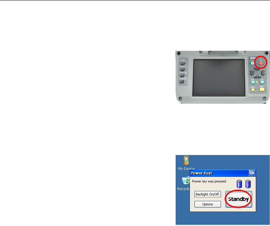
Press [Power] key to turn on the instrument, and
the application program will start up.
Refer to the operation manual for how to use the
application program.
Note – Check the batteries are correctly inserted into the slot if the application
program doesn’t start up even after pressing [power].
Turning off the instrument
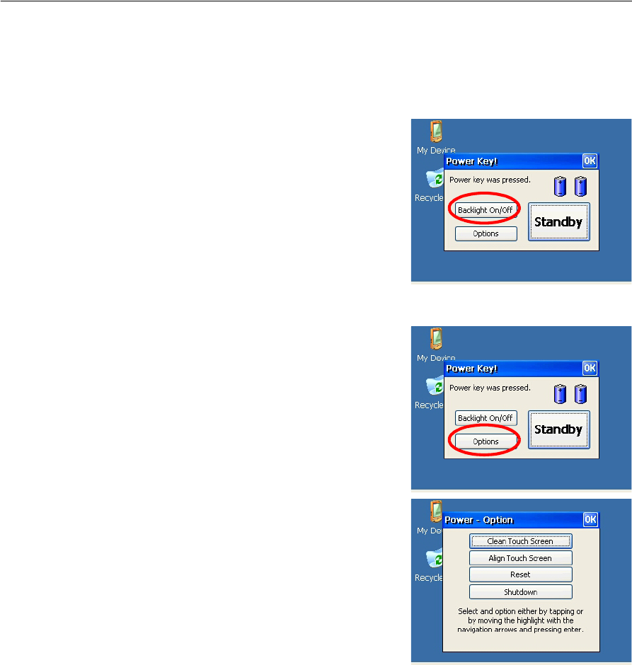
Press [Power] key, and the “Power Key!”
window shown on the right appears.
Tap [Stanby] button on the window to turn off
the instrument.
Tap [OK] button, and the window disappears.
The display returns to the screen shown before
pressing [Power] key.
Note – Stanby
“Stanby” is the function which stops the program running and turns off the
instrument.
Pressing [Power] key again returns to the screen displayed before the instrument is
turned off.
Total Station Nivo Series Instruction Manual 23
Getting Started 3
Basic Operation
Turning on and off the Backlight
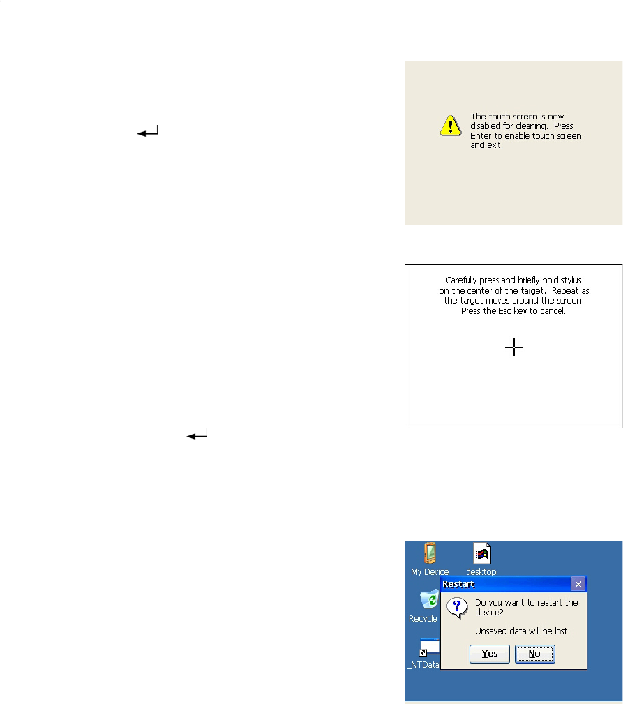
Press [Power] key, and the “Power Key!”
window shown on the right appears.
Tapping [Backlight On/Off] button on the
window switches on/off the back light.
Tap [OK] button, and the window disappears.
The display returns to the screen shown before
pressing [Power] key.
Other functions
Press [Power] key, and the “Power Key!”
window shown on the right appears.
Press [Options] button on the window to display
option menu.
Tap [OK] button, and the window disappears.
The display returns to the screen shown before
pressing [Power] key.
3 Getting Started
24 Total Station Nivo Series Instruction Manual
Cleaning of touch screen
Tapping the menu button [Clean Touch Screen]
disables the touch screen. Use this menu button
for cleaning the touch panel.
Press (Enter) key, and the display returns to
the screen shown before pressing [Power] key.
Adjustment of touch screen
Tapping the menu button [Adjust Touch Screen]
shows the touch panel adjustment window.
By following the instruction in this window, a
gap between the actual tapping point and button
on the window will be corrected.
Press [+] (plus) sign on the screen by stylus pen
over 1 second. The [+] (plus) sign will move to a
corner of the screen when you remove the stylus
pen. Pressing (Enter) key after you press
[+] (plus) sign on center and four corners completes the adjustment of touch screen.
Press [ESC] key to cancel the adjustment.
Reset
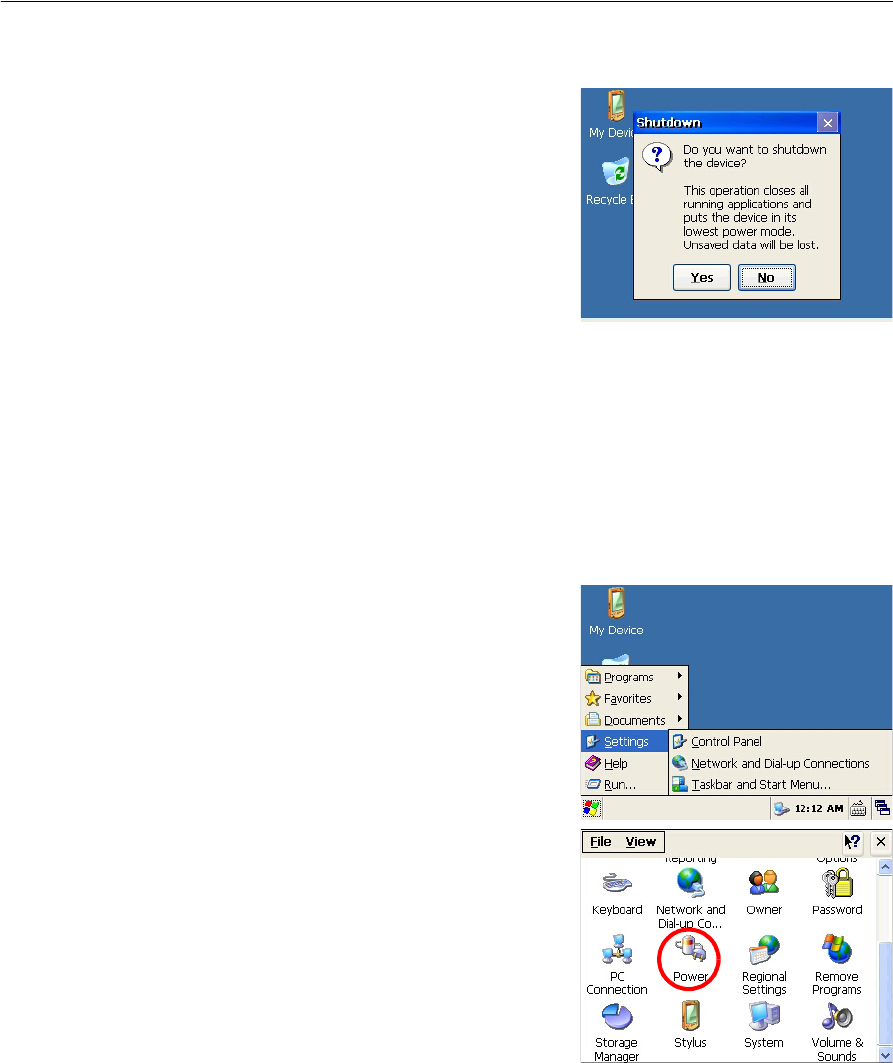
Tap the menu button [Reset], and the window
shown on the right is displayed.
[Reset] stops the program in process and
initializes the Total Station. Use this menu when
the application program does not run normally
because of an unexpected reason.
Tap [Yes] button to execute Reset.
Tap [No] button to cancel Reset and return to the
screen shown before pressing [Power] key.
Note – Once the Reset is executed, data that are not stored in the application program
will be lost.
Total Station Nivo Series Instruction Manual 25
Getting Started 3
Shut down
Tap the menu button [Shutdown], and the
warning window shown on the right is
displayed.
Tap [Yes] button to execute Shut down.
Tap [No] button to cancel Shut down and return
to the screen shown before pressing [Power]
key.
Note – Executing Shut down completely turns off the Total Station.
Note – Executing Shut down ends the application program and the data that are not
stored in the program will be lost.
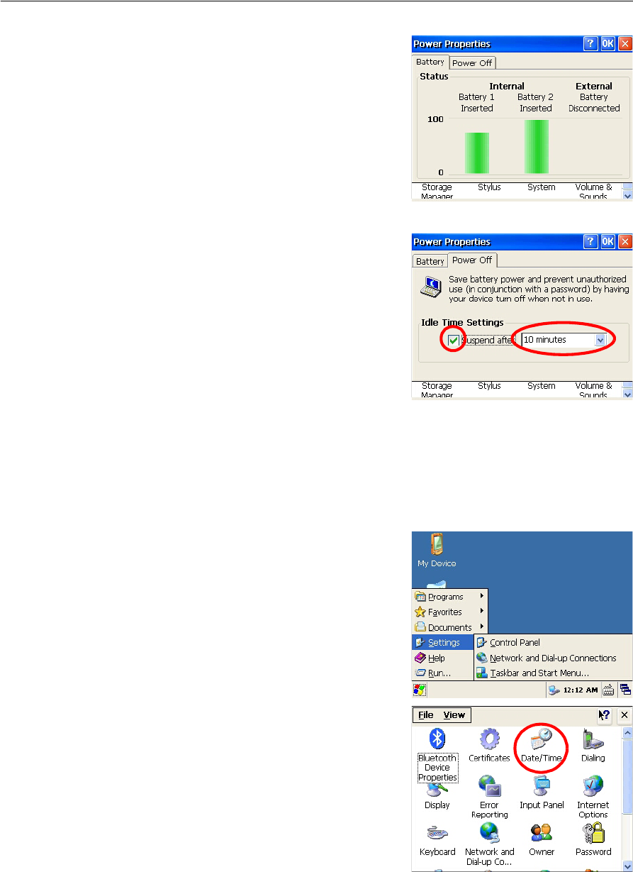
Auto power off setting
Auto power off function saves the consumption of electricity by switching the Total
Station to the standby mode when it is not operated for a certain time.
Tap [Windows] button to display the menu.
Select [Settings] to display the sub-menu.
Choose [Control Panel].
Double click [Power] icon.
3 Getting Started
26 Total Station Nivo Series Instruction Manual
The latest battery status is displayed.
Choose [Power Off] tab.
Time setting window is displayed.
Check the check box of [Suspend after] in the
“Idle Time Settings” field.
Select time from the pull down menu.
Selectable time is 5/10/30 minutes.
The suspend mode check box will be cleared if
time is not selected from the pull down menu.
Tap [OK] button to complete the setting.
Note – Suspend mode and standby mode are the same status.
Date/Time settings
This function allows date and time setting of the Total Station
Tap [Windows] button to display the menu.
Select [Settings] to display the sub menu.
Choose [Control Panel].
Double click [Date/Time] icon.

Total Station Nivo Series Instruction Manual 27
Getting Started 3
Current set date and time are displayed.
Set date, time and time zone.
Tap [Apply] button to fix the set values.
Tap [OK] button to complete the setting process.

3 Getting Started
28 Total Station Nivo Series Instruction Manual

CHAPTER
4
Total Station Nivo Series Instruction Manual 29
Checking and Adjustment 4
In this chapter:
QAdjusting the Electronic Level
QChecking and Adjusting the Circular Level
QChecking and Adjusting the Optical/Laser Plummet
QZero Point Errors of Vertical Scale and Horizontal Angle Corrections
QChecking the Instrument Constant
QChecking the Laser Pointer
4 Checking and Adjustment
30 Total Station Nivo Series Instruction Manual
Adjusting the Electronic Level
Adjustment of the electronic level is done by Zero point errors of vertical scale and
horizontal angle corrections. For detailed instruction, please see page 31.
Checking and Adjusting the Circular Level
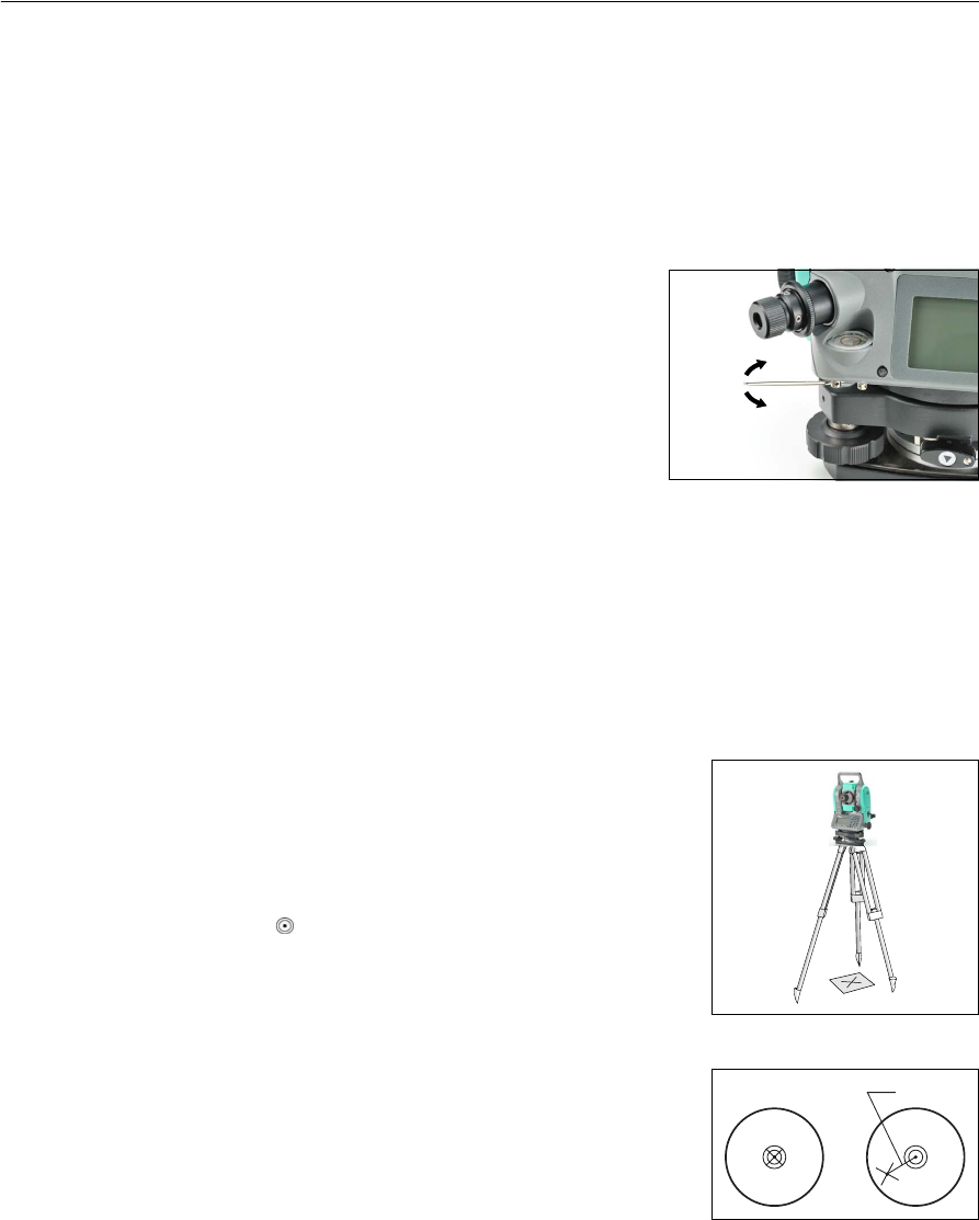
Once you have checked and adjusted the electronic
level, check the circular level.
If the bubble is not in the center of the level, use the
adjusting pin to rotate the three adjustment screws
of either circular level on the instrument main body
or tribrach until the bubble is centered.
Checking and Adjusting the Optical/Laser Plummet
The optical axis of the plummet must be aligned with the vertical axis of the
instrument.
To check and adjust the optical/laser plummet:
1. Place the instrument on the tripod. You do not have to level the instrument.
2. Place a thick sheet of paper marked with an X on
the ground below the instrument.
While you are looking through the optical
plummet, adjust the leveling screws until the
image of the X is in the center of the reticle
mark .
For laser plummet, adjust the laser pointer to the
X.
3. Rotate the alidade 180°.
If the marked image is in the same position in the
center of the reticle mark, no adjustment is
required
For laser plummet, if the laser pointer is on the X,
no adjustment is required.
P

Total Station Nivo Series Instruction Manual 31
Checking and Adjustment 4
4. If the image or laser pointer is not in the same
position, adjust the optical or laser plummet:
a. Use the supplied hexagonal wrench to
turn the adjustment screws until the
image of the X is in Position P. Position
P is the center point of the line
connecting the X and the center of the
reticle mark .
b. Repeat from Step 2.
For laser plummet adjustment, a cap needs to be removed.
Zero Point Errors of Vertical Scale and Horizontal Angle Corrections
Checking
1. Set up the instrument on the tripod.
2. Follow the leveling procedures described in Leveling, page 15.
3. Flip the telescope to the Face-1 position.
4. Sight a target that is within 45° of the horizontal plane.
5. Read the vertical angle from the VA1 field in the Basic Measurement Screen
(BMS).
6. Rotate the instrument 180° and flip the telescope to the Face-2 position.
7. Read the vertical angle from the VA2 field.
8. Add the two vertical angles together, VA1 + VA2.
–No adjustment is required if the zero reference for vertical angles (VA
zero setting) is set to Zenith, and VA1 + VA2 equals 360°.
–No adjustment is required if the zero reference for vertical angles (VA
zero setting) is set to Horizon, and VA1 + VA2 is either 180° or 540°.
–An adjustment is required if VA1 + VA2 is not one of the values listed
above.
Note – The difference between the vertical angle reading the relevant angle (either
360° for Zenith, or 180° or 540° for Horizon) is called the altitude constant.
4 Checking and Adjustment
32 Total Station Nivo Series Instruction Manual
Adjusting
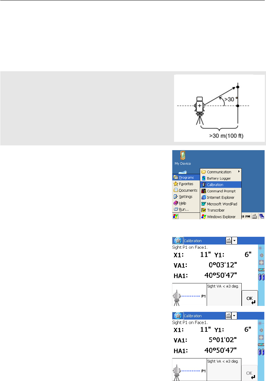
There are two steps in the calibration program. Usually you only complete the first
step that is described below, because the trunnion axis is finely adjusted mechanically.
To make a major adjustment to the trunnion axis error compensation, however, you
can complete the second step that is described below and make three sets of
observations.
To enter the calibration program, tap [Windows]
button to display the menu. Select [Program] to
show the sub-menu. Choose [Calibration].
First step
1. Take an F1 measurement to a target on the
horizon. Tap [OK] button.
The vertical angle is shown in the
V0 dir= Horiz setting.
If you sight a target that has a VA of more
than 3°, a warning message appears and
[OK] button becomes disabled.
To set the parameters for trunnion axis error compensation, establish
two targets at a horizontal distance of at least 30 m from the instrument.
The first target should be placed on the horizontal plane and the second
should be more than 30° above the horizontal plane. Before you set the
trunnion axis compensation value, you must complete three sets of
F1/F2 observations to these two points. Even if you complete the
second step, the instrument cannot store a trunnion axis error
compensation of more than 30". If the error is more than 30", the
instrument needs a mechanical check.
VA1 Face-1 vertical angle (tilt-off value)
HA1 Face-1 horizontal angle (tilt-off value)
X1 Face-1 X axis tilt value
Y1 Face-1 Y axis tilt value
Second
target
First
target
Total Station Nivo Series Instruction Manual 33
Checking and Adjustment 4
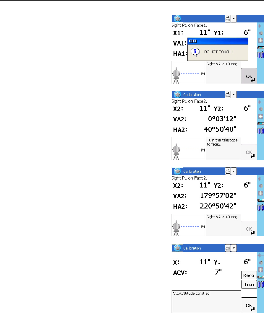
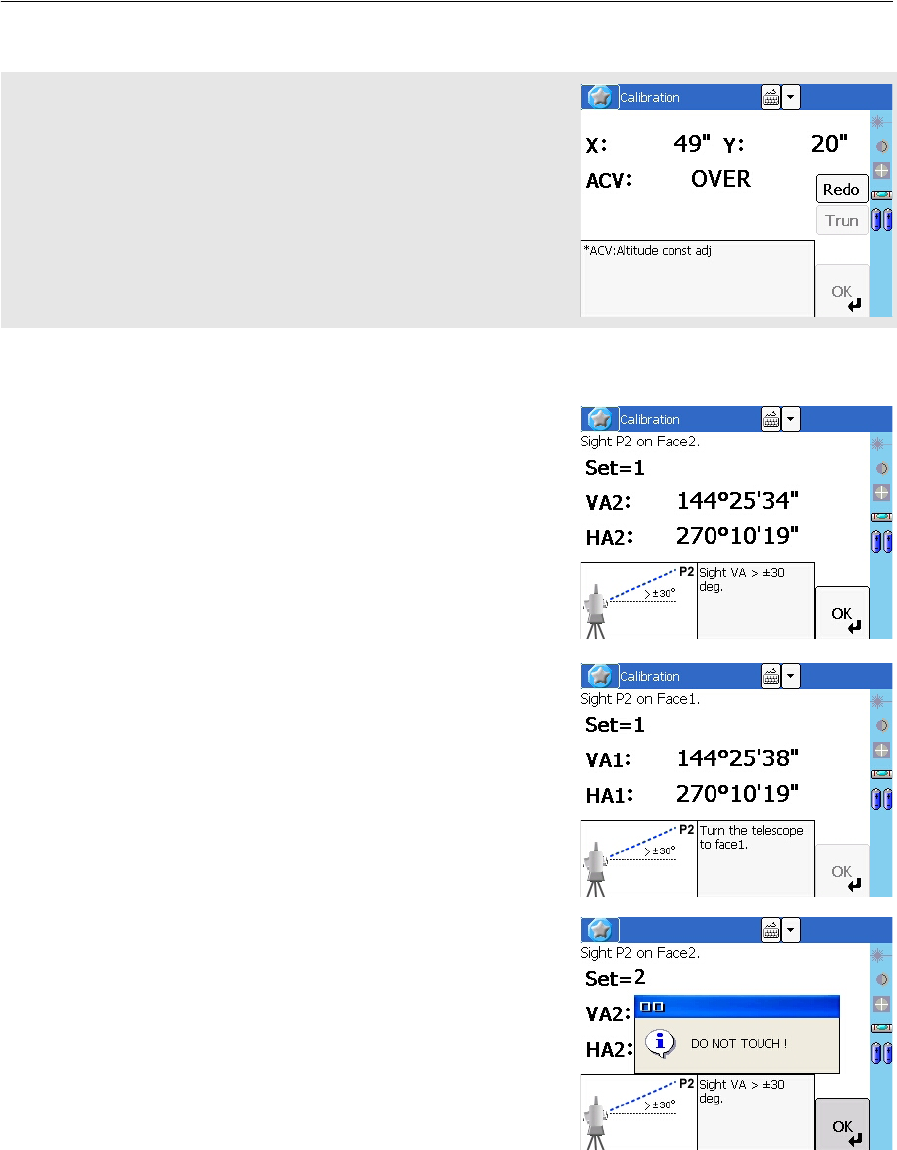
When you have taken the measurement,
the message changes from DO NOT
TOUCH! to Turn to F2.
2. Take an F2 measurement to the same
target. Tap [OK].
When the observation on F2 is completed,
three parameters are displayed.
3. Do one of the following:
–To return to the first observation
screen, tap [Redo].
–To set parameters on the instrument,
tap [OK].
4. To go to the second step (trunnion axis
compensation), tap [Trun].
VA2 Face-2 vertical angle (tilt-off value)
HA2 Face-2 horizontal angle (tilt-off value)
X2 Face-2 X axis tilt value
Y2 Face-2 Y axis tilt value
4 Checking and Adjustment
34 Total Station Nivo Series Instruction Manual
Second step
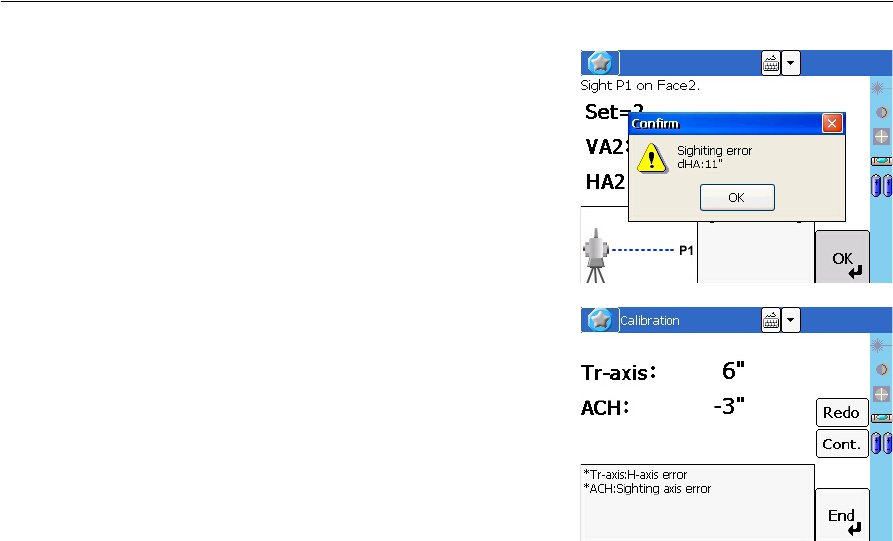
1. Sight the second target that is placed more
than 30 degrees above the horizontal
plane.
2. Tap [OK] to take angle measurements in
the following order:
–Face-2 to P2
–Face-1 to P2
–Face-1 to P1 (Horizontal)
–Face-2 to P1 (Horizontal)
–Face-2 to P2
–Face-1 to P2
–Face-1 to P1 (Horizontal)
–Face-2 to P1 (Horizontal)
–Face-2 to P2
–Face-1 to P2
If the HA corr. setting is set to OFF, the ACH parameter is not applied to
horizontal angle readings. If this setting is set to ON, both of the ACH
and trunnion-axis parameters are applied to HA. If you do not complete
the second step, the trunnion-axis parameter remains set to zero, and
only the ACH parameter is applied. If ACV, ACH, X, or Y is out of range,
OVER appears. Press any key to return to the first observation screen.
Total Station Nivo Series Instruction Manual 35
Checking and Adjustment 4
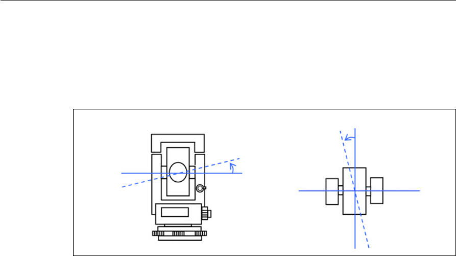
The tolerance in angle reading to each
direction is 10". To maintain the accuracy
of the instrument, you must take shots
with extreme care. If the dHA to the same
direction is more than 10", an error
message appears, and you must remeasure
all three sets of points.
After three sets of F1/F2 observations, the
instrument calculates the trunnion axis
parameter and the updated ACH (the
average of each set).
3. Do one of the following:
–To return to the measurement screen
for the first set of F1 measurements,
tap [Redo].
–To go to the next set of observations
for a more accurate result, tap [Cont.]. You can record up to ten sets.
–To store the parameter and return to the BMS, tap [End].
4. If HA corr. is set to OFF when you finish updating the trunnion axis parameter,
a message appears. The message asks if you want to change the setting. To
change the setting, tap [Yes].
4 Checking and Adjustment
36 Total Station Nivo Series Instruction Manual
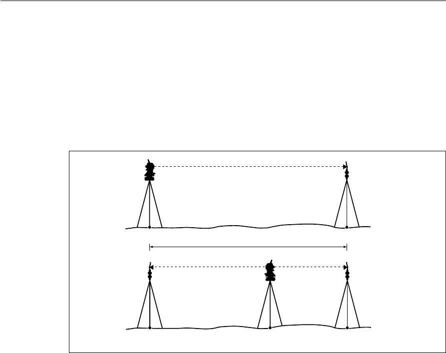
Trunnion axis compensation
The trunnion axis error is reported when the vertical axis and the trunnion axis
(horizontal axis) are not perpendicular to each other. The sighting axis error is from
the sighting and the trunnion axes. These two errors can be compensated by applying
the Tr-axis and ACH parameters on this instrument to horizontal angle readings.
Because the amount of compensation changes according to the vertical angle, when
compensation is enabled there is a slight movement in horizontal angle even if you
clamp the tangent screw.
Tr-axis
ACH
Total Station Nivo Series Instruction Manual 37
Checking and Adjustment 4
Checking the Instrument Constant
The instrument constant is a numerical value used to automatically correct for the
displacement between the mechanical and electrical centers when measuring
distances. The instrument constant is set by the manufacturer before the instrument is
shipped. However, to ensure the highest operational accuracy, we recommend that
you check the instrument constant several times a year.
To check the instrument constant, you can either compare a correctly measured base
line with the distance measured by the EDM, or follow the procedure below.
To check the instrument constant:
1. Set up the instrument at Point P, in as flat an area as possible.
2. Set up a reflector prism at Point Q, 100 m away from Point P. Make sure that
you take the prism constant into account.
3. Measure the distance between Point P and Point Q (PQ).
4. Install a reflector prism on the tripod at Point P.
5. Set up another tripod at Point R, on the line between Point P and Point Q.
6. Transfer the Nivo series instrument to the tripod at Point R.
7. Measure the distance from Point R to Point P (RP), and from Point R to
Point Q (RQ).
8. Calculate the difference between the value of PQ and the value of RP + RQ.
9. Move the Nivo series instrument to other points on the line between Point P
and Point Q.
10. Repeat Step 5 through Step 9 ten times or so.
11. Calculate the average of all the differences.
The error range is within 3 mm. If the error is out of range, contact your dealer.
About 100 m
PQ
PRQ

4 Checking and Adjustment
38 Total Station Nivo Series Instruction Manual
Checking the Laser Pointer
The Nivo series total station uses a red laser beam to a laser pointer. The laser pointer
is coaxial with the line of sight of the telescope. If the instrument is well adjusted, the
red laser pointer coincides with the line of sight. External influences such as shock or
large temperature fluctuations can displace the red laser pointer relative to the line of
sight.

CHAPTER
5
Total Station Nivo Series Instruction Manual 39
Specifications 5
In this chapter:
QMain Body
QStandard Components
QExternal Device Connector

5 Specifications
40 Total Station Nivo Series Instruction Manual
Main Body
Telescope
Measurement range
Distances shorter than 1.5 m (4.92 ft) cannot be measured with this EDM.
Measurement range with no haze, visibility over 40 km (25 miles)
•The target should not receive direct sunlight.
•“Reference target” refers to a white, highly reflective material. (KGC90%)
•The maximum measurement range of Nivo2.C is 500 m in the reflectorless
mode.
Tube length 125 mm (4.91 in.)
Magnification 30 X
Effective diameter of objective
Nivo2.C 40 mm (1.57 in.)
EDM 45 mm (1.77 in.)
Nivo3.C/Nivo5.C 45 mm (1.77 in.)
EDM 50 mm (1.97 in.)
Image Erect
Field of view 1°20'
2.3 m at 100 m (2.3 ft at 100 ft)
Resolving power 3.0''
Focusing distance 1.5 m to infinity (4.92 ft to infinity)
Nivo2.C
Prism mode
Reflector sheet (5 cm x 5 cm) 270 m (886 ft)
Standard prism (1P) 3,000 m (9,840 ft)
Reflectorless mode
Reference target 300 m (984 ft)
Nivo3.C/Nivo5.C
Prism mode
Reflector sheet (5 cm x 5 cm) 300 m (984 ft)
Standard prism (1P) 5,000 m (16,400 ft)
Reflectorless mode
Reference target 300 m (984 ft)

Total Station Nivo Series Instruction Manual 41
Specifications 5
Distance precision
Nivo2.C
Precise mode
Prism ± (2 + 2 ppm × D) mm (–20 °C to +50 °C)
Reflectorless ± (3 + 2 ppm × D) mm (–20 °C to +50 °C)
Normal mode
Prism ± (10 + 5 ppm × D) mm
Reflectorless ± (10 + 5 ppm × D) mm
ISO17123-4 for Prism measurement
Nivo3.C/Nivo5.C
Precise mode
Prism ± (3 + 2 ppm × D) mm (–10 °C to +40 °C)
± (3 + 3 ppm × D) mm
(–20 °C to –10 °C, +40 °C to +50 °C)
Reflectorless ± (3 + 2 ppm × D) mm (–10 °C to +40 °C)
± (3 + 3 ppm × D) mm
(–20 °C to –10 °C, +40 °C to +50 °C)
Normal mode
Prism ± (10 + 5 ppm × D) mm
Reflectorless ± (10 + 5 ppm × D) mm

5 Specifications
42 Total Station Nivo Series Instruction Manual
Measurement intervals
Measurement intervals may vary with the measuring distance or weather conditions.
For the initial measurement, it may take few more seconds.
Angle measurement
Tilt sensor
Nivo2.C
Precise mode
Prism 1.6 sec.
Reflectorless 2.1 sec.
Normal mode
Prism 1.2 sec.
Reflectorless 1.2 sec.
Prism offset correction –999 mm to +999 mm (1 mm step)
Nivo3.C/Nivo5.C
Precise mode
Prism 1.5 sec.
Reflectorless 1.8 sec.
Normal mode
Prism 0.8 sec.
Reflectorless 1.0 sec.
Prism offset correction –999 mm to +999 mm (1 mm step)
Reading system Absolute encoder
Diametrical reading on HA/VA
Minimum display increment
360° 1''/5''/10"
400G 0.2 mgon/1 mgon/2 mgon
MIL6400 0.005 MIL/0.02 MIL/0.05 MIL
DIN18723 accuracy
Nivo2.C 2''/0.6 mgon
Nivo3.C 3''/1.0 mgon
Nivo5.C 5''/1.5 mgon
Method Liquid-electric detection (Dual axis)
Compensation range ±3'

Total Station Nivo Series Instruction Manual 43
Specifications 5
Tangent screw
Tribrach
Level
Optical plummet
Optional laser plummet
Display and keypad
Type Friction clutch endless fine motion
Type Detachable
Electronic level Displayed on the LCD
Circular level vial Sensitivity 10'/2 mm
Image Erect
Magnification 3×
Field of view 5°
Focusing range 0.5 m (1.6 ft) to infinity
Wave length 635 nm
Laser class Class 2
Focusing range ∞
Laser diameter Approx. 2 mm
Face 1 display QVGA,16 bit color, TFT LCD, backlit (320 x 240 pixel)
Face 2 display Backlit, graphic LCD (128 x 64 pixel)
Face 1 keys 14 keys
Face 2 keys 4 keys

5 Specifications
44 Total Station Nivo Series Instruction Manual
Connections in the instrument
Battery pack
Tested at 25 °C (nominal temperature). Operation times may vary depending on the
condition and deterioration of the battery.
Environmental performance
Dimensions
Communications
RS-232C Maximum baud rate 38400 bps asynchronous
USB Host and Client
Class 2 Bluetooth 2.0 EDR+
External power supply input voltage 4.5 V to 5.2 V DC
Output voltage 3.8 V DC rechargeable
Continuous operation time
Nivo2.C
Continuous distance/angle measurement approx 12 hours
Distance/angle measurement every 30 seconds approx 26 hours
Continuous angle measurement approx 28 hours
Nivo3.C/Nivo5.C
Continuous distance/angle measurement approx 7.5 hours
Distance/angle measurement every 30 seconds approx 16 hours
Continuous angle measurement approx 20 hours
Operating temperature range –20 °C through +50 °C (–4 °F through +122 °F)
Storage temperature range –25 °C through +60 °C (–13 °F through +140 °F)
Main unit 149 mm W x 145 mm D x 306 mm H
Carrying case 435 mm W x 206 mm D x 297 mm H

Total Station Nivo Series Instruction Manual 45
Specifications 5
Weight
Environmental protection
Main unit w/o battery
Nivo2.C 3.9 kg (8.6 lbs)
Nivo3.C/Nivo5.C 3.8 kg (8.4 lbs)
Battery 0.1 kg (0.2 lbs)
Carrying case 2.3 kg (5.1 lbs)
Charger and AC adapter 0.4 kg (0.99 lbs), approx.
Watertight/dust-proof protection IP66

5 Specifications
46 Total Station Nivo Series Instruction Manual
Standard Components
•Instrument main body
•Battery pack (X 2)
•Battery charger
•AC adapter
•Adjustment pin, Allen wrench
•Objective lens cap
•Vinyl cover
•Total Station Nivo Series Instruction Manual (this document)
•Carrying case
•Shoulder strap (X 2)
External Device Connector
This connector can be used to connect to an external power source or to communicate
with an external device.
Before using the external device connector, make sure that the external device meets
the specifications below.
CCAUTION – Except for the connection shown in Figure 6.1on page 50, use of this connector is
at your own risk.
CCAUTION – Use only the male connectors specified above. Using other connectors will
damage the instrument.
Input voltage 4.5 V to 5.2 V DC
System RS-232C
Signal level ±9 V standard
Maximum baud rate 38400 bps asynchronous
Compatible male connector Hirose HR10A-7P-6P or HR10-7P-6P

Total Station Nivo Series Instruction Manual 47
Specifications 5
The external device connector is a Hirose HR 10A-7R-6S female connector. The
pinouts for connecting it to an external device connector are shown below:
CCAUTION – Use only the pin connections shown above. Using other connections will damage
the instrument.
CCAUTION – The Nivo series total station has different pin assignment from other models of
Nikon total station.
To connect to an external power source, supply power to Pin 4 (power terminal) and
Pin 5 (ground terminal) on the instrument. The instrument will use the external power
source even if the internal battery packs are attached.
CCAUTION – Make sure that the power supplied is within the rated input range (4.5 V to 5.2 V
DC, 1 A maximum). Power supplied outside this range will damage the instrument.
To communicate with an external device, connect the RS-232C signal from the
external device to Pin 1 (input terminal) and to Pin 2 (output terminal) on the
instrument.
Cap the data output/external power input connector securely while not in use. The
instrument is not watertight if the cap is not attached or not attached securely, and
when the data output/external power input connector is in use.
The instrument can be damaged by static electricity from the human body discharged
through the data output/external power input connector. Before handling the
instrument, touch any other conductive material once to remove static electricity.
Pin Signal Description
1 RXD Receive data (Input)
2 TXD Send data (Output)
3 NC No connection
4VPower
5 GND Ground
6 NC No connection
HRS
16
25
34

5 Specifications
48 Total Station Nivo Series Instruction Manual

CHAPTER
6
Total Station Nivo Series Instruction Manual 49
System Diagrams 6
In this chapter:
QSystem Components
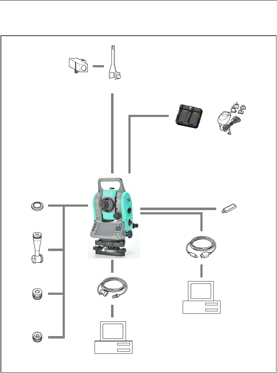
6 System Diagrams
50 Total Station Nivo Series Instruction Manual
System Components
Figure 6.1 Measurement side
Tubular
Compass
Tubular compass
attachment
Nivo series
Connecting cable
Personal computer
Diagonal
Battery charger
Low-power
eyepiece
High-power
eyepiece
Solar filter
AC adapter and
plug adapter
(9 pin, USB)
USB cable
USB memory
eyepiece
Personal computer
Total Station Nivo Series Instruction Manual 51
System Diagrams 6
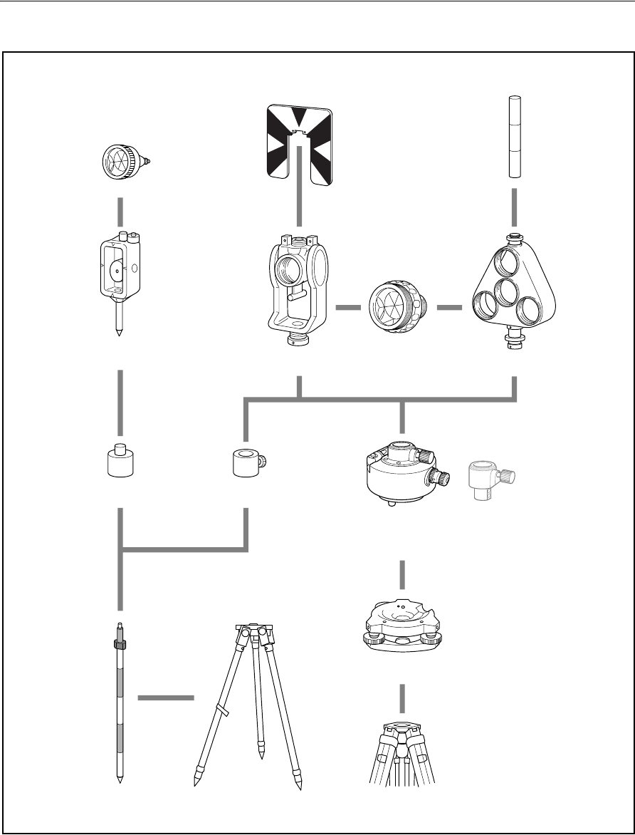
Figure 6.2 Prism reflector side
Note – Nivo series must be used with the Tribrach W30 or W30b.
Mini prism C
Mini prism
holder
Mini prism
adapter
Tel esc op ic
prism pole
Coaxial target plate
for single prism
Tiltable single
prism holder
Prism adapter
Tripod for telescopic prism pole
Standard round
single prism C
Ta r ge t p o l e
Triple prism
holder
Tribrach adapter 15
Nikon tripod
Tribrach W30/W30b
Height adjustment
adapter is not used.

6 System Diagrams
52 Total Station Nivo Series Instruction Manual

© xxxx–xxxx, Trimble Navigation LImited. All rights reserved. Trimble is a trademark of Trimble Navigation Limited registered in the United
States Patent and Trademark Office and other countries. Nikon is a registered trademark of Nikon. All other trademarks are the property of
their respective owners. PN xxxxxxx-xxx (xx/xx)
NORTH AMERICA (Survey)
Tripod Data Systems
P O Box 947
Corvallis, OR 97339
USA
+1-541-753-9322 Phone
+1-541-757-7439 Fax
www.tdsway.com
www.trimble.com