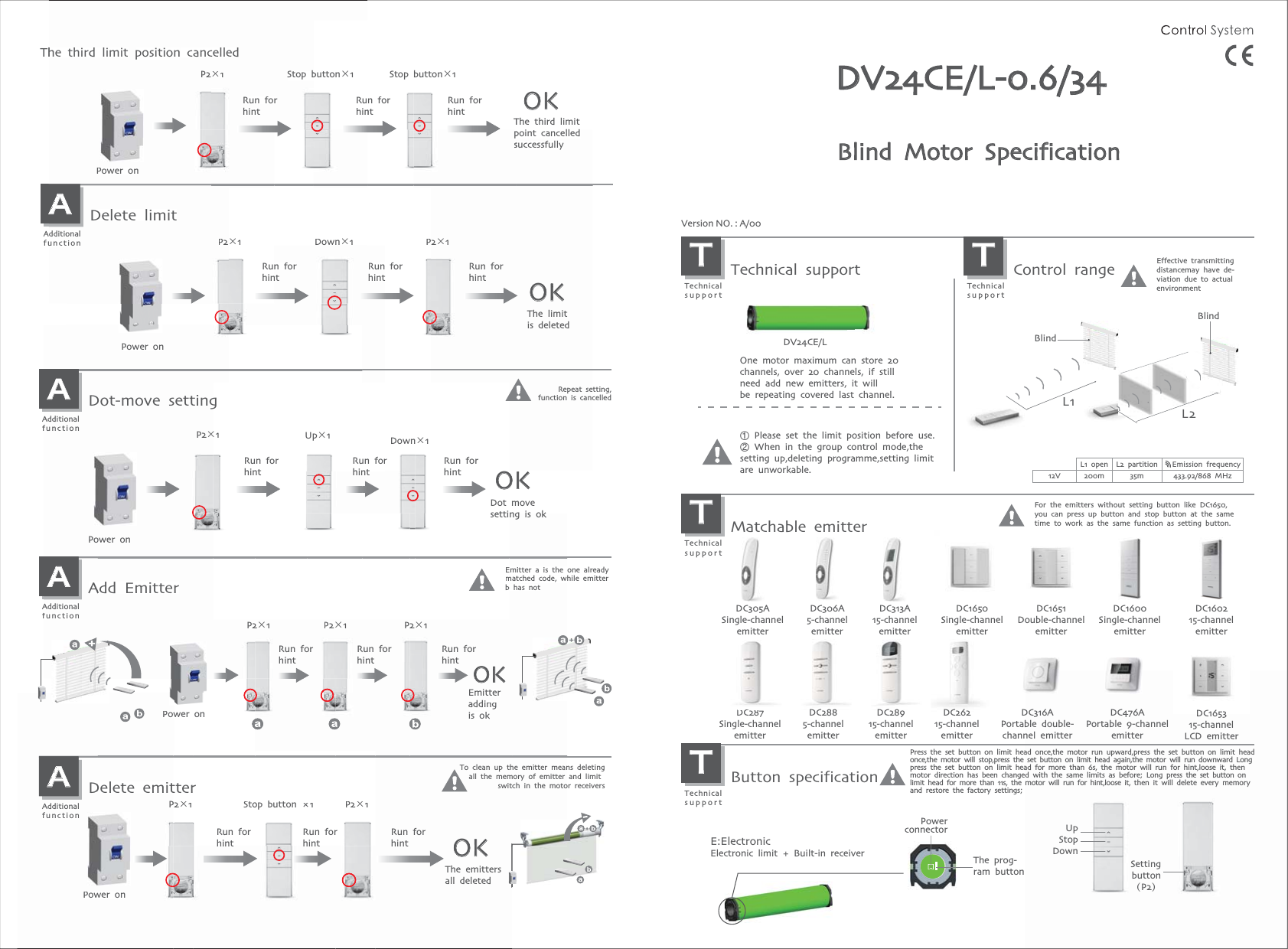
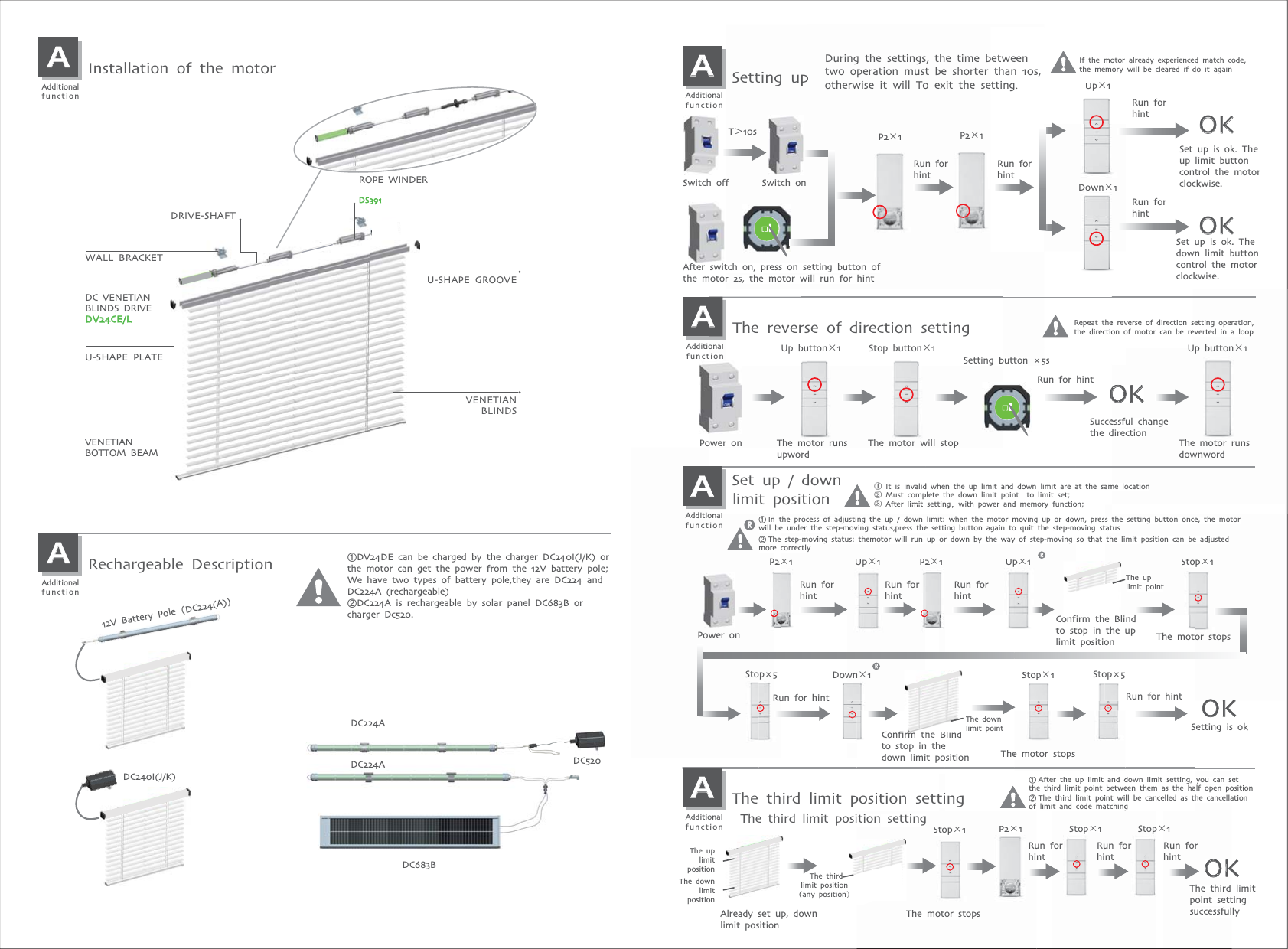
NINGBO DOOYA MECHANIC and ELECTRONIC TECHNOLOGY DV24CE DC Venetian Blinds Drive User Manual 123

NINGBO DOOYA MECHANIC & ELECTRONIC TECHNOLOGY CO., LTD. DC Venetian Blinds Drive 123

Manual

L1L2Blind Blind DV24CE/L-0.6/34Blind Motor SpecificationThe prog-ram buttonprog-buttonUpStopDownSettingbutton(P2)E:Electronic Electronic limit + Built-in receiverPowerconnectorP2×1 P2×1OKDown×1PAAdditionalfunctionDelete limitPower onPower onThe limit is deletedRun forhintRun forhintRun forhintRun forhintRun forhintRun forhintControl rangeTTechnical supportEffective transmitting distancemay have de-viation due to actual environmentL1 open L2 partition Emission frequency200m 35m 433.92/868 MHzVersion NO. : A/00Technical supportTTechnical supportDC1651Double-channelemitterDC165315-channelLCD emitterMatchable emitterTTechnical supportFor the emitters without setting button like DC1650, you can press up button and stop button at the same time to work as the same function as setting button.DC160215-channelemitterDC306A5-channelemitterDC305ASingle-channelemitterDC1650Single-channelemitterDC313A15-channelemitterDC287Single-channelemitterDC2885-channelemitterDC28915-channelemitterDC316APortable double-channel emitterDC476APortable 9-channelemitterDC26215-channelemitterDC1600Single-channelemitterCButton specificationTTechnical supportP2×1 P2×1 P2×1OKEmitter adding is okAAdditionalfunctionAdd EmitterEmitter a is the one already matched code, while emitter b has notEmbOKPower onP22×1P2×1AAdditionalfunctionAAdd EmitterrP2×1Up×1Down×1Power onPower onAAdditionalfunctionDot-move settingDot movesetting is okRepeat setting,function is cancelledPower onAAdditionalfunctionDelete emitterPowwer Power onAAdditionalfunctionDDelete emitP2×1tter Emitng addikis okonP2×1The emitters all deletedOKStop button ×1ttterP22×1rP2×1Stoop button ×1To clean up the emitter means deletingall the memory of emitter and limit switch in the motor receiversOKRun forhintRun forhintRun forhintRun forhintRun forhintRun forhintRun forhintRun forhintRun forhintThe third limit position cancelledThe third limit point cancelled successfullyOne motor maximum can store 20channels, over 20 channels, if stillneed add new emitters, it will be repeating covered last channel.ᴺ Please set the limit position before use. ᴻ When in the group control mode,the setting up,deleting programme,setting limit are unworkable. 12VDV24CE/LPress the set button on limit head once,the motor run upward,press the set button on limit head once,the motor will stop,press the set button on limit head again,the motor will run downward Long press the set button on limit head for more than 6s, the motor will run for hint,loose it, then motor direction has been changed with the same limits as before; Long press the set button on limit head for more than 11s, the motor will run for hint,loose it, then it will delete every memory and restore the factory settings;P21Down1AdditioonaluncttionDelete limitPower onRun forhinnthe third limitposition cancP2×1P2×1Run forhintcelled×1Stop button×12×1PRun forhintTpsn forntDown×1Ruhinbutton×1 Stop button×1DV24CEQ/L-0.6/34
Set up is ok. The down limit button control the motor clockwise.OKAAdditionalfunctionRechargeable Description AAdditionalfunctionInstallation of the motorDC683BᴺDV24DE can be charged by the charger DC240I(J/K) or the motor can get the power from the 12V battery pole;We have two types of battery pole,they are DC224 andDC224A (rechargeable)ᴻDC224A is rechargeable by solar panel DC683B or charger Dc520.DC224ADC520DC224A12V Battery Pole᷉DC224(A)᷊DC240I(J/K)U-SHAPE PLATEU-SHAPE GROOVEVENETIANBOTTOM BEAMVENETIANBLINDSDC VENETIANBLINDS DRIVEDV24CE/LWALL BRACKETROPE WINDERDS391DRIVE-SHAFTThe uplimit pointAfter switch on, press on setting button ofthe motor 2s, the motor will run for hintIf the motor already experienced match code,the memory will be cleared if do it againtch on, press on ser 2s, the motor wP2×1etting button ofill run for hintP2×1P2×1Up×1Down×1Set dalready experiencewill be cleared if dIf the motor the memory Up×1Down×1Set up is ok. The up limit button control the motor clockwise.OKAAdditionalfunctionSetting upDuring the settings, the time between two operation must be shorter than 10s, otherwise it will To exit the setting.ᴺIn the process of adjusting the up / down limit: when the motor moving up or down, press the setting button once, the motorwill be under the step-moving status,press the setting button again to quit the step-moving statusᴻThe step-moving status: themotor will run up or down by the way of step-moving so that the limit position can be adjusted more correctlyᴺInwill ᴻThmoreP2×1 P2×1Up×1 tbehe e c2×the process of adjusting the up / down e under the step-moving status,press thestep-moving status: themotor will run correctly×1PUp×1Up×1wn, presmoving stso that when the motor moving up or dow button again to quit the step-mown by the way of step-moving limit: we settingup or de22×1Up×1 Stop×1Stop×1The uplimit points the setting button once, the motortatusthe limit position can be adjusted tStop×1AAdditionalfunctionSet up / down limit positionRun for hint Run for hintStop×1Run for hint OK① It is invalid when the up limit and down limit are at the same location② Must complete the down limit point  to limit set; ③ After limit setting,with power and memory function;Power onStop×5 Stop×5Confirm the Blindto stop in the down limit positionThe motor stopsThe motor stopsSetting is okConfirm the Blindto stop in the uplimit positionDown×1OKStop×1The motor stopsᴺAfter the up limit and down limit setting, you can set the third limit point between them as the half open positionᴻThe third limit point will be cancelled as the cancellationof limit and code matchingThe third limit position settingAAdditionalfunctionThe third limit position settingAlready set up, down limit positionThe third limit point setting successfullyT˚10sSwitch off Switch onThe downlimit pointThe uplimitpositionThe downlimitposition The thirdlimit position(any position)Repeat the reverse of direction setting operation, the direction of motor can be reverted in a loopPower onRun for hintRun for hintRun for hintRun for hintRun for hintRun for hintRun for hintRun for hintSuccessful change the directionSetting button ×5sAAdditionalfunctionThe reverse of direction settingAlSet up / limit posipoower onAonaltionThe reverOKme locationsetting operation,verse of direction se reveverted in a loopof motor can be reon oessful change directionOKKd when the up limit avalidplete the down limit pompsettingmitmit setting,with powerwith power ggSetting bn settingdown tiono① It is inv② Must c③③After li After lirsse of directionThe motor runsupwordThe motor runsdownwordThe motor will stopStop button×1Up button×1 Up button×1he Confirm tBBlindhen thto stop ine down downlimitlimitlimipopo ppositionositionThepe motor stopsStop×1The motor stopstion settingtiposition settingThe downlimit pointP2×1ᴺAftee ththᴻThe limiof P2×1Stop×1Run forhintOKyou can ssetting, alf open poas the hahe cancellaelled as tThe third point settsuccessfulmit m ancedown limer the up limit and deen themird limit point betwell be canthird limit point wigit and code matchingStop×1forStop×1Run forhintRun forhint
FCC STATEMENT 1. This device complies with Part 15 of the FCC Rules. Operation is subject to the following two conditions: (1) This device may not cause harmful interference. (2) This device must accept any interference received, including interference that may cause undesired operation. 2. Changes or modifications not expressly approved by the party responsible for compliance could void the user's authority to operate the equipment.  NOTE: This equipment has been tested and found to comply with the limits for a Class B digital device, pursuant to Part 15 of the FCC Rules. These limits are designed to provide reasonable protection against harmful interference in a residential installation. This equipment generates uses and can radiate radio frequency energy and, if not installed and used in accordance with the instructions, may cause harmful interference to radio communications. However, there is no guarantee that interference will not occur in a particular installation. If this equipment does cause harmful interference to radio or television reception, which can be determined by turning the equipment off and on, the user is encouraged to try to correct the interference by one or more of the following measures:    Reorient or relocate the receiving antenna.    Increase the separation between the equipment and receiver.    Connect the equipment into an outlet on a circuit different from that to which the receiver is connected.    Consult the dealer or an experienced radio/TV technician for help.

Navigation menu