NINGBO DOOYA MECHANIC and ELECTRONIC TECHNOLOGY DV24CE DC Venetian Blinds Drive User Manual 123
NINGBO DOOYA MECHANIC & ELECTRONIC TECHNOLOGY CO., LTD. DC Venetian Blinds Drive 123
Manual
L1
L2
Blind
Blind
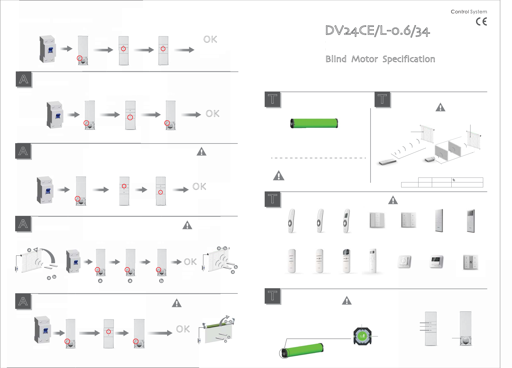
DV24CE/L-0.6/34
Blind Motor Specification
The prog-
ram button
prog-
button
Up
Stop
Down
Setting
button
(P2)
E:Electronic
Electronic limit + Built-in receiver
Power
connector
P2×1 P2×1
OK
Down×1
P
A
Additional
function
Delete limit
Power on
Power on
The limit
is deleted
Run for
hint
Run for
hint
Run for
hint
Run for
hint
Run for
hint
Run for
hint
Control range
T
Technical
support
Effective transmitting
distancemay have de-
viation due to actual
environment
L1 open L2 partition Emission frequency
200m 35m 433.92/868 MHz
Version NO. : A/00
Technical support
T
Technical
support
DC1651
Double-channel
emitter
DC1653
15-channel
LCD emitter
Matchable emitter
T
Technical
support
For the emitters without setting button like DC1650,
you can press up button and stop button at the same
time to work as the same function as setting button.
DC1602
15-channel
emitter
DC306A
5-channel
emitter
DC305A
Single-channel
emitter
DC1650
Single-channel
emitter
DC313A
15-channel
emitter
DC287
Single-channel
emitter
DC288
5-channel
emitter
DC289
15-channel
emitter
DC316A
Portable double-
channel emitter
DC476A
Portable 9-channel
emitter
DC262
15-channel
emitter
DC1600
Single-channel
emitter
C
Button specification
T
Technical
support
P2×1 P2×1 P2×1
OK
Emitter
adding
is ok
A
Additional
function
Add Emitter
Emitter a is the one already
matched code, while emitter
b has not
E
m
b
OK
P
o
wer
o
n
P2
2
×
1
P2
×
1
A
A
ddition
al
fu
nc
tion
A
Ad
d
Em
it
te
r
r
P2×1Up×1Down×1
Power on
Power on
A
Additional
function
Dot-move setting
Dot move
setting is ok
Repeat setting,
function is cancelled
Power on
A
Additional
function
Delete emitter
Pow
w
er
Po
wer
o
n
A
Additional
function
D
D
e
l
ete emi
t
P2×1
tter
Emit
ng
a
ddi
k
is o
k
o
n
P2×1
The emitters
all deleted
OK
Stop button ×1
t
t
te
r
P2
2
×
1
r
P2
×
1
Sto
o
p
b
utton
×
1
To clean up the emitter means deleting
all the memory of emitter and limit
switch in the motor receivers
OK
Run for
hint
Run for
hint
Run for
hint
Run for
hint
Run for
hint
Run for
hint
Run for
hint
Run for
hint
Run for
hint
The third limit position cancelled
The third limit
point cancelled
successfully
One motor maximum can store 20
channels, over 20 channels, if still
need add new emitters, it will
be repeating covered last channel.
ᴺ Please set the limit position before use.
ᴻ When in the group control mode,the
setting up,deleting programme,setting limit
are unworkable. 12V
DV24CE/L
Press the set button on limit head once,the motor run upward,press the set button on limit head
once,the motor will stop,press the set button on limit head again,the motor will run downward Long
press the set button on limit head for more than 6s, the motor will run for hint,loose it, then
motor direction has been changed with the same limits as before; Long press the set button on
limit head for more than 11s, the motor will run for hint,loose it, then it will delete every memory
and restore the factory settings;
P2
1
Down
1
A
dd
i
tio
on
a
l
u
nc
t
tion
Delete limi
t
Po
wer
on
Run
for
hi
n
nt
h
e t
h
ir
d
l
imit
p
os
i
t
i
on c
a
n
c
P2×1
P2
×
1
R
u
n
for
hint
c
e
ll
e
d
×
1
Stop button×1
2
×
1
P
R
u
n
for
hint
T
p
s
n
fo
r
n
t
Down
×
1
R
u
hin
b
utton×1 Stop button×1
DV24CEQ/L-0.6/34
Set up is ok. The
down limit button
control the motor
clockwise.
OK
A
Additional
function
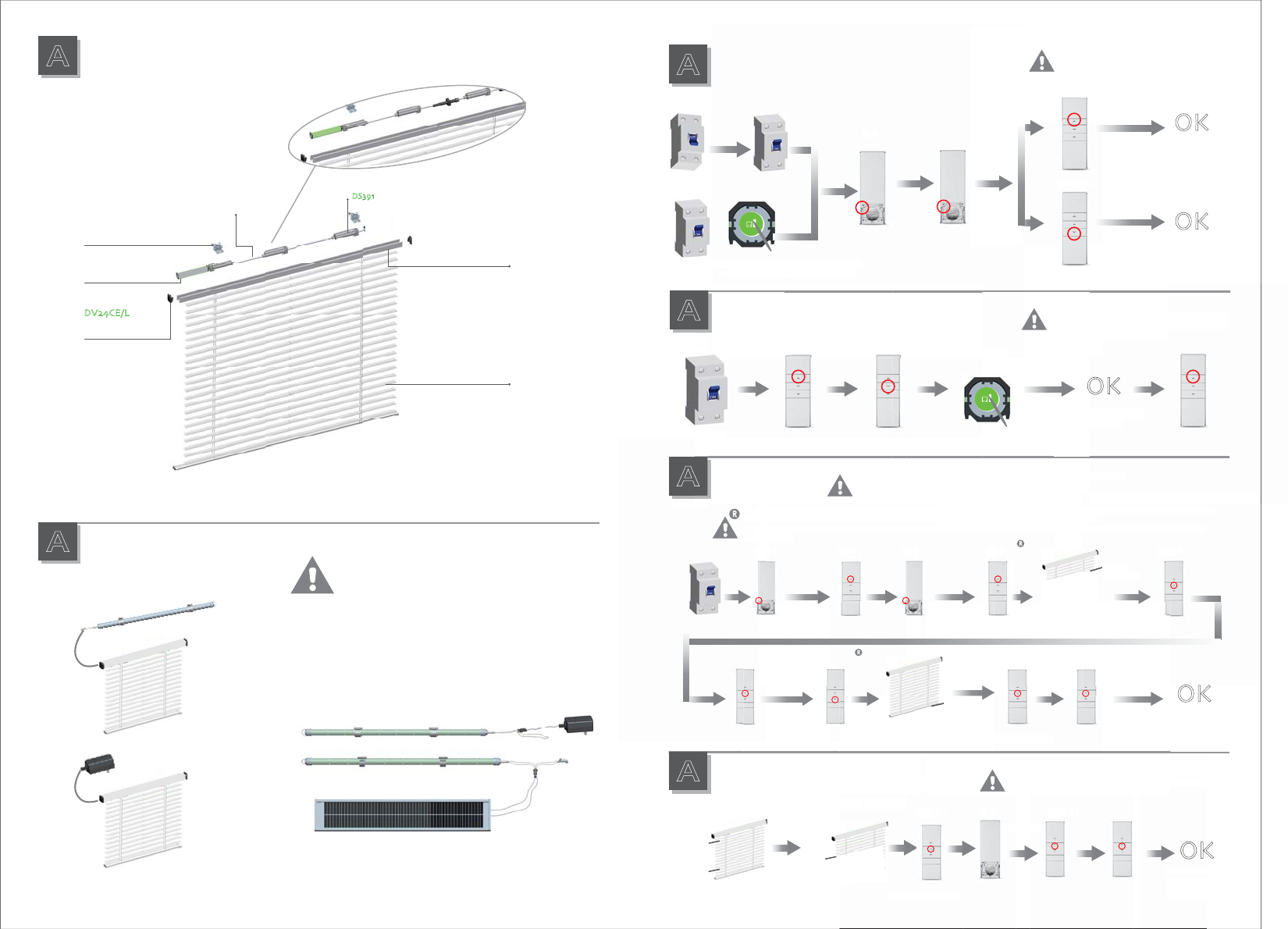
Rechargeable Description
A
Additional
function
Installation of the motor
DC683B
ᴺDV24DE can be charged by the charger DC240I(J/K) or
the motor can get the power from the 12V battery pole;
We have two types of battery pole,they are DC224 and
DC224A (rechargeable)
ᴻDC224A is rechargeable by solar panel DC683B or
charger Dc520.
DC224A
DC520
DC224A
12V Battery Pole᷉DC224(A)᷊
DC240I(J/K)
U-SHAPE PLATE
U-SHAPE GROOVE
VENETIAN
BOTTOM BEAM
VENETIAN
BLINDS
DC VENETIAN
BLINDS DRIVE
DV24CE/L
WALL BRACKET
ROPE WINDER
DS391
DRIVE-SHAFT
The up
limit point
After switch on, press on setting button of
the motor 2s, the motor will run for hint
If the motor already experienced match code,
the memory will be cleared if do it again
t
c
h
on,
p
ress on s
e
r
2s
,
the motor w
P2×1
e
ttin
g
b
utton o
f
ill run for hin
t
P
2×
1
P2×1
Up×1
Down×1
S
et
d
a
l
rea
dy
experienc
e
will be cleared if
d
I
f
t
h
e motor
the memor
y
Up
×
1
Do
wn
×
1
Set up is ok. The
up limit button
control the motor
clockwise.
OK
A
Additional
function
Setting up
During the settings, the time between
two operation must be shorter than 10s,
otherwise it will To exit the setting.
ᴺIn the process of adjusting the up / down limit: when the motor moving up or down, press the setting button once, the motor
will be under the step-moving status,press the setting button again to quit the step-moving status
ᴻThe step-moving status: themotor will run up or down by the way of step-moving so that the limit position can be adjusted
more correctly
ᴺ
In
w
ill
ᴻ
T
h
mor
e
P2×1 P2×1Up×1
t
b
e
h
e
e
c
2
×
t
he process of adjusting the up / down
e
under the ste
p
-movin
g
status
,
p
ress th
e
step-moving status: themotor will run
c
orrectl
y
×
1
P
Up
×
1
Up×1
w
n, pres
m
ovin
g
s
t
so that
w
hen the motor moving up or
dow
button a
g
ain to
q
uit the ste
p
-
m
own by the way of step-movi
ng
limit:
w
e
settin
g
up or d
e
2
2
×
1
Up
×
1 Stop×1
Stop×1
Th
e u
p
l
imit
p
oint
s the setting button once, the motor
t
atus
the limit position can be adjusted
t
S
to
p
×
1
A
Additional
function
Set up / down
limit position
Run for hint Run for hint
Stop
×
1
Ru
n f
o
r hint OK
① It is invalid when the up limit and down limit are at the same location
② Must complete the down limit point to limit set;
③ After limit setting,with power and memory function;
Power on
Stop×5 Stop×5
Confirm the Blind
to stop in the
down limit position
The motor stops
The motor stops
Setting is ok
Confirm the Blind
to stop in the up
limit position
Down×1
OK
Stop×1
The motor stops
ᴺAfter the up limit and down limit setting, you can set
the third limit point between them as the half open position
ᴻThe third limit point will be cancelled as the cancellation
of limit and code matching
The third limit position setting
A
Additional
function
The third limit position setting
Already set up, down
limit position
The third limit
point setting
successfully
T˚10s
Switch off Switch on
The down
limit point
The up
limit
position
The down
limit
position
The third
limit position
(any position)
Repeat the reverse of direction setting operation,
the direction of motor can be reverted in a loop
Power on
Run for hint
Run for
hint
Run for
hint
Run for
hint
Run for
hint
Run for
hint
Run for
hint
Run for
hint
Successful change
the direction
Setting button ×5s
A
Additional
function
The reverse of direction setting
A
l
S
et u
p
/
limit p
o
si
p
o
o
wer
o
n
A
o
na
l
t
i
o
n
T
he reve
r
OK
m
e loca
tion
s
etting operation,
v
erse of direction
s
e
re
v
e
verted in a loo
p
o
f motor can be r
e
o
n
o
e
ssful chan
g
e
d
irecti
on
OK
K
d
when the up limit
a
v
ali
d
p
lete the down limit
p
om
p
setting
mit
mit
setting
,
with power
with
power
g
g
Settin
g
b
n
settin
g
d
own
ti
o
n
o
①
It is in
v
②
Must c
③
③
After li
After
li
rs
s
e of directi
on
The motor runs
upword
The motor runs
downword
The motor will stop
Stop button×1Up button×1 Up button×1
h
e
Confirm t
B
Bli
n
d
he
n
t
h
to s
top
i
n
e
down
down
limi
t
limit
limi
po
po
p
p
osition
osition
T
he
p
e
motor sto
p
s
S
top
×
1
Th
e motor stops
t
i
o
n
sett
i
n
g
ti
p
osition set
t
i
n
g
T
he d
o
w
n
l
imi
t po
int
P2×1
ᴺ
A
f
t
e
e thth
ᴻ
Th
e
lim
i
o
f
P2
×
1
Stop×1
Run for
hint
OK
y
ou can ssettin
g,
a
lf open p
o
a
s the h
a
h
e cance
lla
ell
e
d
as t
T
he thir
d
p
oint set
t
s
uccessful
m
it
m
a
n
c
e
d
own
l
i
m
e
r t
h
e up
l
imit an
d
d
e
en the
m
ird limit point betw
e
ll
b
e ca
n
t
h
ir
d
l
imit point wi
g
i
t and code matchin
g
S
top
×
1
for
Stop×1
Run for
hint
Run for
hint
FCC STATEMENT
1. This device complies with Part 15 of the FCC Rules. Operation is subject to the following two
conditions:
(1) This device may not cause harmful interference.
(2) This device must accept any interference received, including interference that may cause
undesired operation.
2. Changes or modifications not expressly approved by the party responsible for compliance could
void the user's authority to operate the equipment.
NOTE: This equipment has been tested and found to comply with the limits for a Class B digital
device, pursuant to Part 15 of the FCC Rules. These limits are designed to provide reasonable
protection against harmful interference in a residential installation.
This equipment generates uses and can radiate radio frequency energy and, if not installed and
used in accordance with the instructions, may cause harmful interference to radio communications.
However, there is no guarantee that interference will not occur in a particular installation. If this
equipment does cause harmful interference to radio or television reception, which can be
determined by turning the equipment off and on, the user is encouraged to try to correct the
interference by one or more of the following measures:
Reorient or relocate the receiving antenna.
Increase the separation between the equipment and receiver.
Connect the equipment into an outlet on a circuit different from that to which the receiver is
connected.
Consult the dealer or an experienced radio/TV technician for help.