NXP Laboratories UK JN5139M4 JN5139-000-M04 Wireless Microcontroller User Manual ANT 2 4 CW RCL Data Sheets
NXP Laboratories UK Ltd JN5139-000-M04 Wireless Microcontroller ANT 2 4 CW RCL Data Sheets
UserManual.wiki
>
NXP Laboratories UK
>
JN5139M4 User Manual
>
Antenna Info 1
Contents
1.
User Manual
2.
Manual
3.
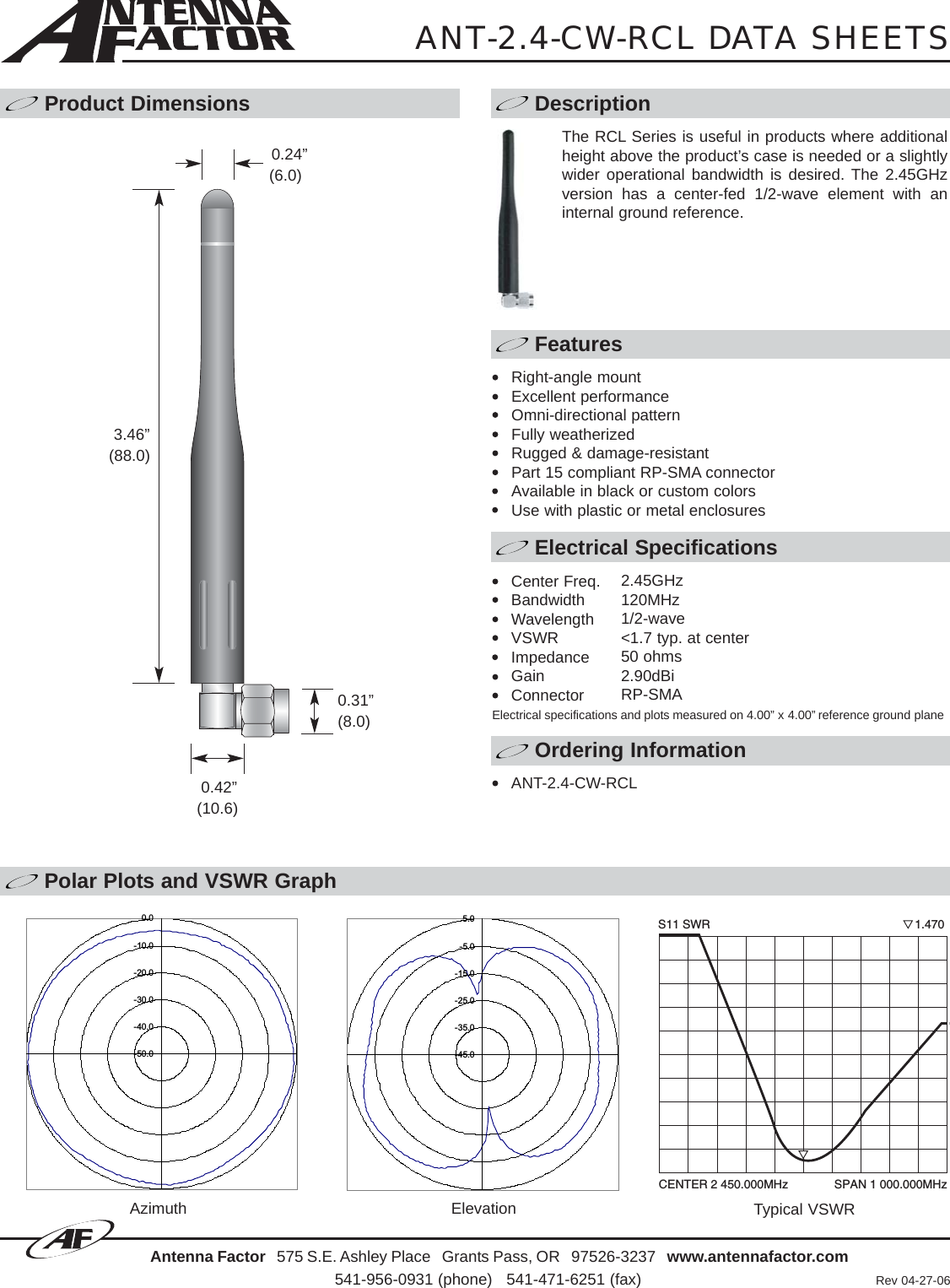
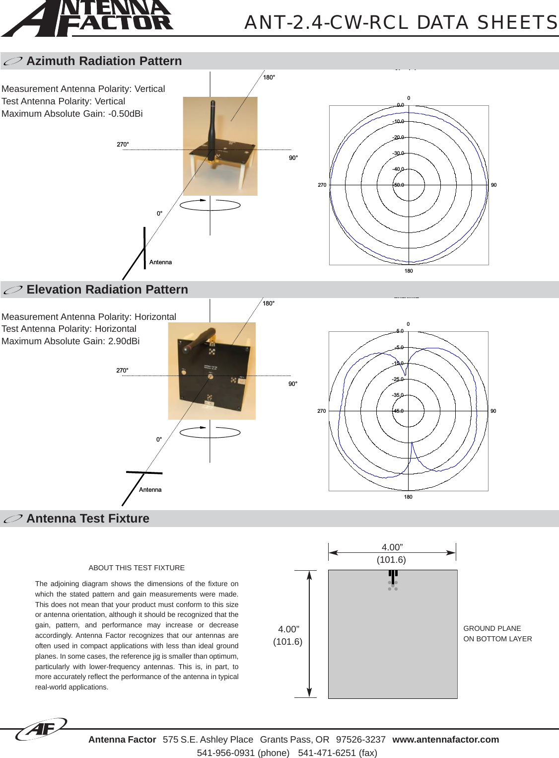
Antenna Info 1
4.
Antenna Info 2
5.
Antenna Info 3
6.
Antenna Info 4
7.
Antenna Info 5
8.
Antenna Info 6
9.
Antenna Info 7
10.
Antenna Info 8
11.
Antenna Info 9
12.
manual
13.
Antenna Info 10
14.
Antenna Info 11
Antenna Info 1
Navigation menu
Upload a User Manual
Namespaces
Wiki Guide
HTML
PDF
Info
Views
User Manual
Discussion / Help
Navigation