NXP Laboratories UK JN5139M4 JN5139-000-M04 Wireless Microcontroller User Manual ANT 2 4 CW RCL Data Sheets
NXP Laboratories UK Ltd JN5139-000-M04 Wireless Microcontroller ANT 2 4 CW RCL Data Sheets
Contents
Antenna Info 1
Polar Plots and VSWR Graph
Antenna Factor 575 S.E. Ashley Place Grants Pass, OR 97526-3237 www.antennafactor.com
541-956-0931 (phone) 541-471-6251 (fax) Rev 04-27-06
Typical VSWR
ANT-2.4-CW-RCL DATA SHEETS
Product Dimensions Description
Features
Electrical Specifications
Ordering Information
Azimuth Elevation
-50.0
-40.0
-30.0
-20.0
-10.0
0.0
-45.0
-35.0
-25.0
-15.0
-5.0
5.0
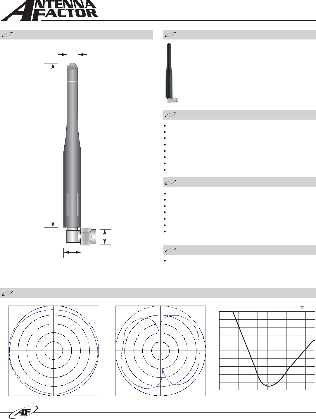
0.24”
(6.0)
0.31”
(8.0)
0.42”
(10.6)
The RCL Series is useful in products where additional
height above the product’s case is needed or a slightly
wider operational bandwidth is desired. The 2.45GHz
version has a center-fed 1/2-wave element with an
internal ground reference.
Right-angle mount
Excellent performance
Omni-directional pattern
Fully weatherized
Rugged & damage-resistant
Part 15 compliant RP-SMA connector
Available in black or custom colors
Use with plastic or metal enclosures
Center Freq.
Bandwidth
Wavelength
VSWR
Impedance
Gain
Connector
Electrical specifications and plots measured on 4.00” x 4.00” reference ground plane
ANT-2.4-CW-RCL
CENTER 2 450.000MHz SPAN 1 000.000MHz
S11 SWR 1.470
3.46”
(88.0)
2.45GHz
120MHz
1/2-wave
<1.7 typ. at center
50 ohms
2.90dBi
RP-SMA
Absolute
Gain of AUT
-50.0
-40.0
-30.0
-20.0
-10.0
0.0
0
90
180
270
90°
270°
180°
0°
A
ntenna
Antenna Factor 575 S.E. Ashley Place Grants Pass, OR 97526-3237 www.antennafactor.com
541-956-0931 (phone) 541-471-6251 (fax)
ANT-2.4-CW-RCL DATA SHEETS
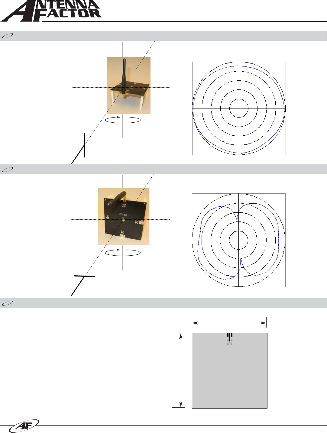
Azimuth Radiation Pattern
Elevation Radiation Pattern
Absolute
Gain of AUT
-45.0
-35.0
-25.0
-15.0
-5.0
5.0
0
90
180
270
90°
270°
180°
0°
A
ntenna
Measurement Antenna Polarity: Vertical
Test Antenna Polarity: Vertical
Maximum Absolute Gain: -0.50dBi
Measurement Antenna Polarity: Horizontal
Test Antenna Polarity: Horizontal
Maximum Absolute Gain: 2.90dBi
4.00”
(101.6)
4.00”
(101.6)
GROUND PLANE
ON BOTTOM LAYER
Antenna Test Fixture
The adjoining diagram shows the dimensions of the fixture on
which the stated pattern and gain measurements were made.
This does not mean that your product must conform to this size
or antenna orientation, although it should be recognized that the
gain, pattern, and performance may increase or decrease
accordingly. Antenna Factor recognizes that our antennas are
often used in compact applications with less than ideal ground
planes. In some cases, the reference jig is smaller than optimum,
particularly with lower-frequency antennas. This is, in part, to
more accurately reflect the performance of the antenna in typical
real-world applications.
ABOUT THIS TEST FIXTURE