NXP Laboratories UK JN5148M3 IEEE 802.15.4 Wireless Microcontroller User Manual ANT 2 4 CW RCT xx Data Sheets
NXP Laboratories UK Ltd IEEE 802.15.4 Wireless Microcontroller ANT 2 4 CW RCT xx Data Sheets
Contents
- 1. Chip Manual
- 2. User Manual
- 3. Antenna 1 of 36
- 4. Antenna 2 of 36
- 5. Antenna 3 of 36
- 6. Antenna 4 of 36
- 7. Antenna 5 of 36
- 8. Antenna 6 of 36
- 9. Antenna 7 of 36
- 10. Antenna 8 of 36
- 11. Antenna 9 of 36
- 12. Antenna 10 of 36
- 13. Antenna 11 of 36
- 14. Antenna 12 of 36
- 15. Antenna 13 of 36
- 16. Antenna 14 of 36
- 17. Antenna 15 of 36
- 18. Antenna 16 of 36
- 19. Antenna 17 of 36
- 20. Antenna 19 of 36
- 21. Antenna 20 of 36
- 22. Antenna 21 of 36
- 23. Antenna 22 of 36
- 24. Antenna 23 of 36
- 25. Antenna 24 of 36
Antenna 20 of 36
Polar Plots and VSWR Graph
Antenna Factor 575 S.E. Ashley Place Grants Pass, OR 97526-3237 www.antennafactor.com
541-956-0931 (phone) 541-471-6251 (fax) Rev 05-01-06
Typical VSWR
ANT-2.4-CW-RCT-xx DATA SHEETS
Product Dimensions Description
Features
Electrical Specifications
Ordering Information
Azimuth Elevation
-45.0
-35.0
-25.0
-15.0
-5.0
5.0
9
-45.0
-35.0
-25.0
-15.0
-5.0
5.0
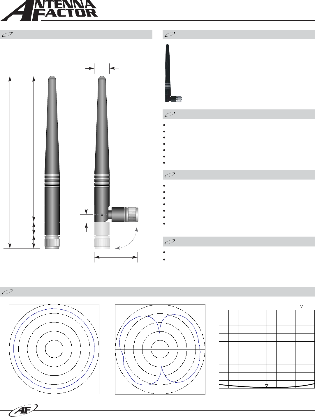
The RCT 1/2-wave 2.4GHz antenna delivers outstanding
performance and orientation flexibility in a compact
physical package. The antenna’s innovative articulating
base allows it to tilt and swivel for optimum orientation.
The RCT mounts quickly via an SMA or FCC Part 15
compliant RP-SMA connector.
Tilts and rotates
Very low VSWR
Excellent performance
Omni-directional pattern
Fully weatherized
Rugged and damage-resistant
RP-SMA or SMA connector
0.35”
(9.0)
0.39”
(10.0)
0.33”
(8.4)
3.76”
(95.6)
0.20”
(5.1)
1.10”
(28.0)
4.44”
(113.0)
Center Freq.
Bandwidth
Wavelength
VSWR
Impedance
Gain
Connector
2.45GHz
120MHz
1/2-wave
<1.9 typ. at center
50 ohms
2.20dBi
RP-SMA or SMA
Electrical specifications and plots measured on 4.00”x 4.00” reference ground plane
CENTER 2 450.000MHz SPAN 200.000MHz
S11 SWR 1.033
ANT-2.4-CW-RCT-RP (with RP-SMA connector)
ANT-2.4-CW-RCT-SS (with SMA connector)
Absolute
Gain of AUT
-45.0
-35.0
-25.0
-15.0
-5.0
5.0
0
90
180
270
90°
270°
180°
0°
A
ntenna
Antenna Factor 575 S.E. Ashley Place Grants Pass, OR 97526-3237 www.antennafactor.com
541-956-0931 (phone) 541-471-6251 (fax)
ANT-2.4-CW-RCT-xx DATA SHEETS
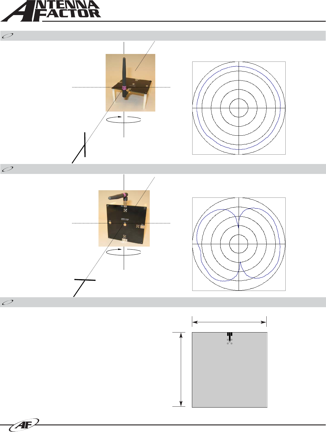
Azimuth Radiation Pattern
Elevation Radiation Pattern
Absolute
Gain of AUT
-45.0
-35.0
-25.0
-15.0
-5.0
5.0
0
90
180
270
90°
270°
180°
0°
A
ntenna
Measurement Antenna Polarity: Vertical
Test Antenna Polarity: Vertical
Maximum Absolute Gain: 0.40dBi
Measurement Antenna Polarity: Horizontal
Test Antenna Polarity: Horizontal
Maximum Absolute Gain: 2.20dBi
4.00”
(101.6)
4.00”
(101.6)
GROUND PLANE
ON BOTTOM LAYER
Antenna Test Fixture
The adjoining diagram shows the dimensions of the fixture on
which the stated pattern and gain measurements were made.
This does not mean that your product must conform to this size
or antenna orientation, although it should be recognized that the
gain, pattern, and performance may increase or decrease
accordingly. Antenna Factor recognizes that our antennas are
often used in compact applications with less than ideal ground
planes. In some cases, the reference jig is smaller than optimum,
particularly with lower-frequency antennas. This is, in part, to
more accurately reflect the performance of the antenna in typical
real-world applications.
ABOUT THIS TEST FIXTURE