Nanjing Signway Information Technology SWH5186 Media Player Board User Manual
Nanjing Signway Information Technology Co., Ltd Media Player Board
User Manual

Specification V2.0
Media Player Board SWH-5186
©2017 Nanjing Signway Technology Co., Ltd.

FCC Statement
Changes or modifications not expressly approved by the party responsible for compliance could void the
user's authority to operate the equipment.
This equipment has been tested and found to comply with the limits for a Class B digital device, pursuant
to Part 15 of the FCC Rules. These limits are designed to provide reasonable protection against harmful
interference in a residential installation. This equipment generates uses and can radiate radio frequency
energy and, if not installed and used in accordance with the
instructions, may cause harmful interference to radio communications. However, there is no guarantee
that interference will not occur in a particular installation. If this equipment does cause harmful
interference to radio or television reception, which can be determined by turning the equipment off and
on, the user is encouraged to try to correct the interference by one or more of the following measures:
-- Reorient or relocate the receiving antenna.
-- Increase the separation between the equipment and receiver.
-- Connect the equipment into an outlet on a circuit different from that to which the receiver is connected.
-- Consult the dealer or an experienced radio/TV technician for help
This device complies with part 15 of the FCC rules. Operation is subject to the following two conditions
(1)this device may not cause harmful interference, and (2) this device must accept any interference
received, including interference that may cause undesired operation.
Revision history
Revision Revision date Principle changes
V1.0 Oct. 2016 Create based on SWH-5186 V1.0
V2.1 Sept. 2017 Create based on SWH-5180 V2.0
Copyright © 2017 Nanjing Signway Technology Co., Ltd. All rights reserved.
The distance between the product and body is more than 20cm

I
Contents
1Overview................................................................................................................................................................... 2
1.1 Introduction.......................................................................................................................................................2
1.2 Features............................................................................................................................................................. 2
2Specification.............................................................................................................................................................. 3
3Profile........................................................................................................................................................................ 5
3.1 Profile.................................................................................................................................................................5
3.2 Dimensions........................................................................................................................................................ 7
3.3 Structure............................................................................................................................................................ 8
4Interfaces...................................................................................................................................................................9
4.1 Interface Layout.................................................................................................................................................9
4.2 Interface Description....................................................................................................................................... 10
5Electrical Performance............................................................................................................................................21

Signway Media Player Board SWH-5180 SPEC V2.0 2
1Overview
1.1 Introduction
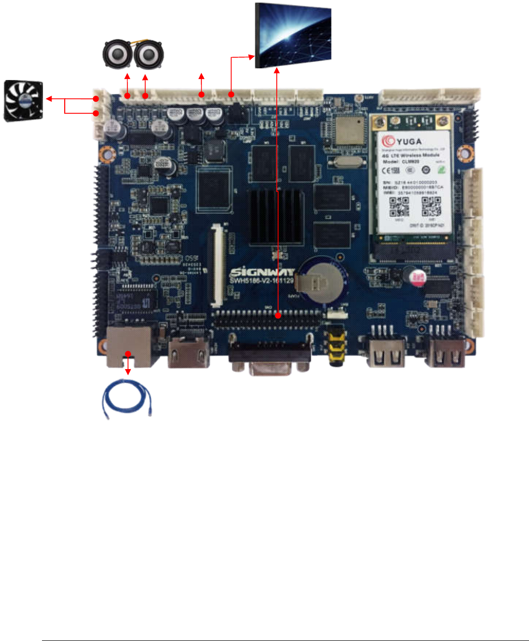
SWH-5186 multimedia network player board is designed based on Rockchip RK3288 chip. Which
is CPU frequency up to 1.8GHZ and quad-core architecture Cortex-A17 and DDR3 2G memory
and 8G of storage. These super-performance ensure high-speed run of terminals . The most
eye-catching of the board is supporting 4K H.264 decoding. In addition, this board has rich
peripheral interfaces, including TTL, RS232, GPIO multiple expansion interface and HDMI input +
HDMI, LVDS, VGA three outputs to support the industry mainstream USB / serial port Equipment;
It support camera and printer and identification terminal and two-dimensional code scanner and IC
card reader and fingerprint reader and other mainstream peripherals.
1.2 Features
(1) the classic version, the new configuration
·CPU’s frequency is 1.8GHZ
·Quad-core CPU
·DDR3 2G memory and 8G storage (expandable TF / USB)
·Android 5.1 system
(2) complete module, with on-demand
·Mainstream 3G / 4G module
·Printer, two-dimensional code scanner, camera, identification terminal, fingerprint recognition
·NFC identification module
·Thermal sensation and gravity sensing module
·Wireless charging module
(3) rich peripheral interface, flexible choice and expansion
·3 TTL or 1 TTL + 2 RS232 (standard)
·6 TTL or 4 TTL + 2 RS232 (Optional)
·6 USB2.0 interface and 5 GPIO interface
·HDMI, LVDS, VGA three output
·HDMI input (optional)
Chapter 1
Signway Media Player Board SWH-5180 SPEC V2.0 3
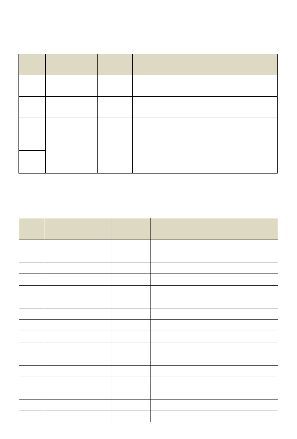
2Specification
Hardware Configuration
CPU Rockchip RK3288 + ARM Quad-core Cortex A17 CPU (Up to 1.8GHz)
RAM HYNIX DDR3 2Gbyte
Storage 8GB eMMC Memory (extensible TF/USB)
GPU ARM Quad Mali-764 GPU
Resolution 4K H.264 Decoding
OS
OS Android 5.1
Contents Support Video/Image/Text/logo/Date/Time/Weekday/Weather split-screen display
and background image
Media Formats
Media Formats Video: MPEG1, MPEG2, MPEG4, H.264, WMV, MKV, TS, flv
Audio: MP3
Image: JPG, JPEG, BMP, PNG, GIF
Interfaces
Power Supply ×1
Video Output VGA×1 (optional)
HDMI×1
LVDS×1,40 Pin, 2.0mm, Double Row
Video Input HDMI IN×1
Audio Output ×1, Linear output, 3.5mm headphone jack
×2, 2 Pin 2.0mm, Stereo CLASS-D Amplifier, direct for 2*8W/8Ω Speaker
Internet ×1, 10/100M Ethernet
WIFI(802.11bgn)×1, BT4.0×1
PCIE Slot(2G/3G Module)×1
USB2.0 USB OTG×1(can be used as HOST)
USB HOST×5 (J28 and 3G modules share a USB interface)
Backlight ×2, 6 Pin, 2.0mm
Fan ×2, 2 Pin, 2.0mm
IR ×1, 7 Pin, 2.0mm, Red/Green LED
Chapter 1 Overview
Signway Media Player Board SWH-5180 SPEC V2.0 4
Extension 3 TTL or 1 TTL + 2 RS232 (standard)
6 TTL or 4 TTL + 2 RS232 (Optional)
SPI×1
GPIO×5
I2C×2
MIC x1
TF Card Slot ×1
SIM Card Slot ×1
Other Features
RTC Time synchronization over network and time saving when power failure
IR Input Specified remote of NEC format
Electrical Parameter
Input Power Switching Power(STB,5VSB,5V,12V), 10 Pin, 2.00mm
Single 12V (Need to short J41)
Signway Media Player Board SWH-5180 SPEC V2.0 5
USB_OTG
Note:
Serial port type (TTL / RS232) will be different according to the option.
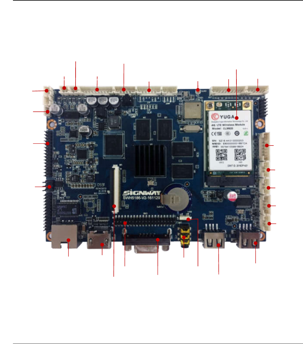
3Profile
3.1 Profile
Front View
Speaker Left
Speaker Right
Main Power Input
Back light
Remote WiFi/BT Antenna
WiFi/BT Antenna
SPI Extension
USB Extension
USB Extension
3G Extension
USB Extension
LAN HDMI
LVDS Output
VGA(optional)
Fan
MIC
Audio
U_BOOT USB
TTL
TTL
MIPI(optional)
HDMI IN
EDP
Chapter 2Specification
Signway Media Player Board SWH-5180 SPEC V2.0 6
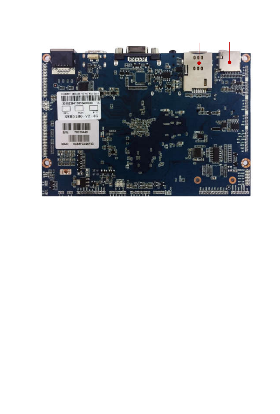
Rear View
TF
SIM
Chapter 2Profile
Signway Media Player Board SWH-5180 SPEC V2.0 7
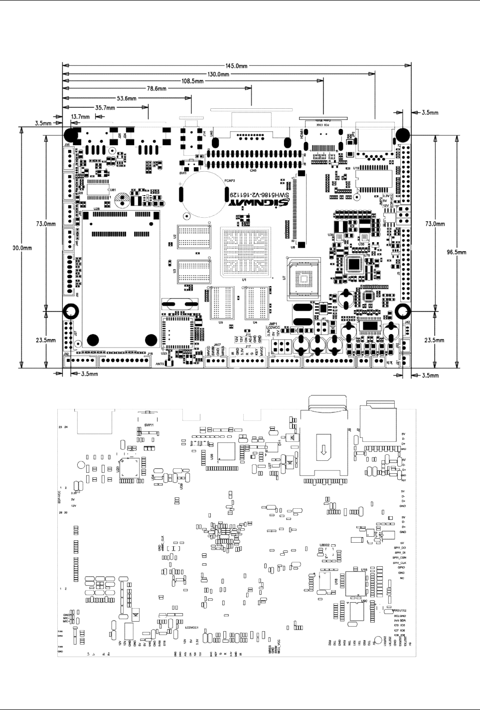
3.2 Dimensions
Length:145mm, Width:100mm,Front Max. Height: 9mm,Rear Max Height:4mm, Screw Hole:Φ3.5mm
Signway Media Player Board SWH-5180 SPEC V2.0 8
3.3 Structure
Right
LAN/WLAN
Speaker
LVDS line
Backlight
Left
Fan
Power

Signway Media Player Board SWH-5180 SPEC V2.0 9
3G/4G
J32
J35
CN5
J28
HDMI_OUT
U8 SW1
J24
4Interfaces
4.1 Interface Layout
Front
J18
J42
JMP2
J4 J5
JMP1 ANT5 J18
J17
J11
J41
J7
J37
J38
J46
J45
RJ45
VGA_OUT
AU_OUT USB
Chapter 3 Profile
Signway Media Player Board SWH-5180 SPEC V2.0 10
Rear
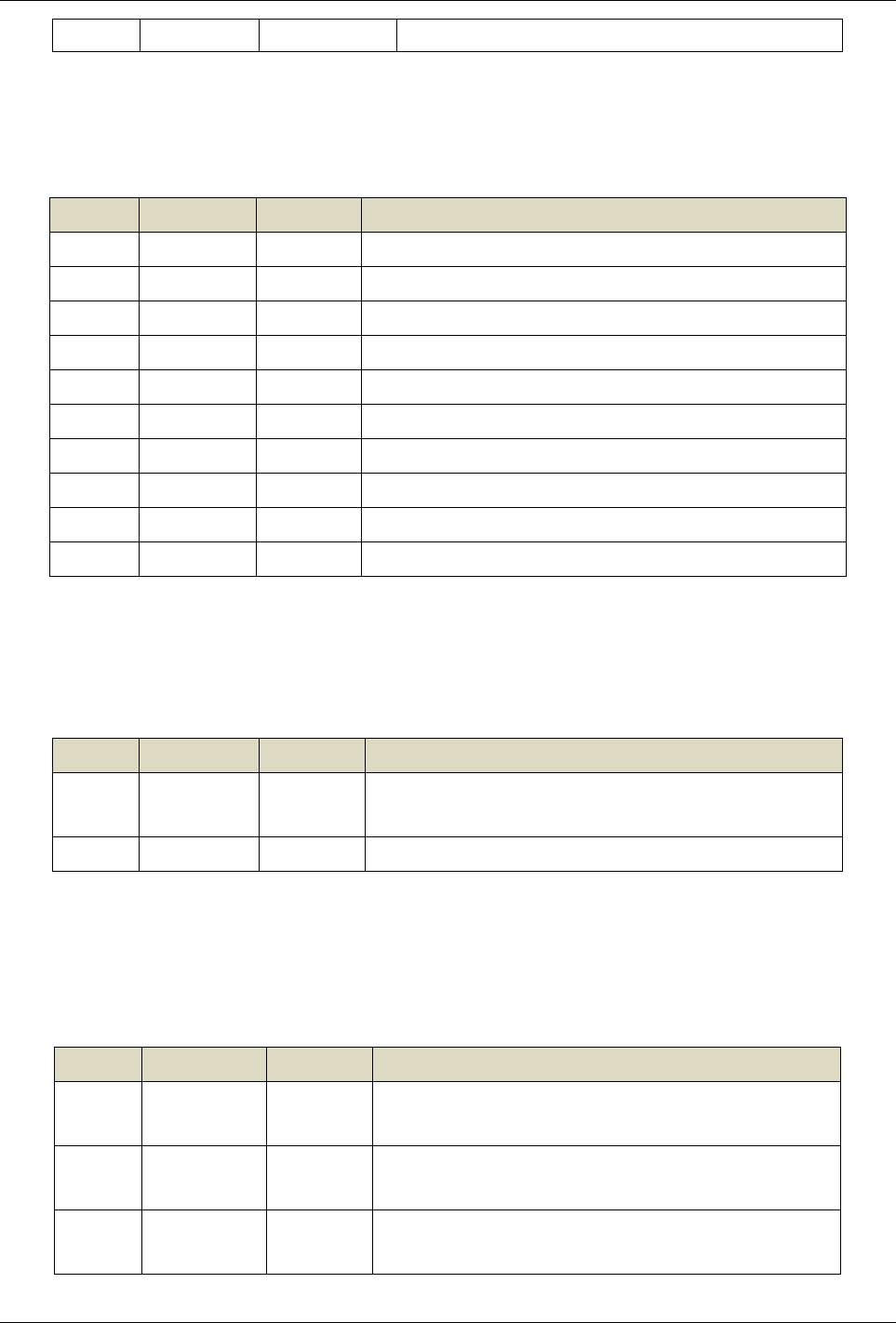
4.2 Interface Description
·J4 Left Speaker Output
Pin No. Pin Name Type Description
1 L- Output Left channel negative
2 L+ Output Left channel positive
·J5 Right Speaker Output
Pin No. Pin Name Type Description
1 R- Output Right channel negative
2 R+ Output Right channel positive
·J7 Main Power Input
Pin No. Pin Name Type Description
J2
J9
Chapter 3 Interfaces
Signway Media Player Board SWH-5180 SPEC V2.0 11
112V Input Total Power Input, 12V
2
3GND Ground Ground
4
55V Input Total Power Input, 5V
6
7GND Ground Ground
8
9 5VSB Input Standby Powe, 5V
10 STB Output Standby power control
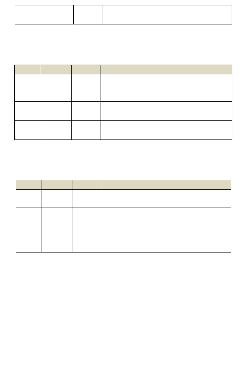
·J11 Backlight Inverter Control
Pin No. Pin Name Type Description
1
12V Power
Output
+12V Backlight Power Output, Switch Controlled,
Max. Current: 3A
Large size multi-tube backlight with more than 3A
current requires separate power supply
2
3 ON Output 3.3V Backlight On/Off Signal, High/Low Configured
4 ADJ Output Backlight DIMMING Control
5GND Ground Ground
6
·J17 Remote Receiver/ Working Indicator/ Button Interface
Pin No. Pin Name Type Description
1 IR Input Remote Receiver Input
2 GND Ground Ground
3 3.3V Power
Output Remote Power 3.3V
4 R Red Light Indicates Standby State
5 G Green Light Indicates Working State
6 KEY Input Outer Button Input
7 MVC Power 3.3V Power Output
Chapter 3 Interfaces
Signway Media Player Board SWH-5180 SPEC V2.0 12
Output
·J18 TTL Serial Port
Pin No. Pin Name Type Description
1 NC Reserved
2 NC Reserved
3 GND Ground Ground
4 RX4 Input UART Data Input, TTL
5 TX4 Output UART Data Output, TTL
6 NC Reserved
7 NC Reserved
8 NC Reserved
9 NC Reserved
10 5V Output 5V
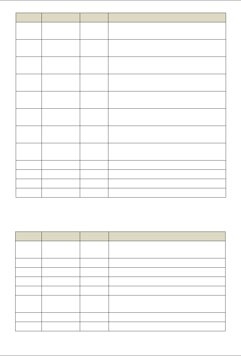
·J21/ J22 Fan
Pin No. Pin Name Type Description
1 FAN Power
Output Fan Power Output, 12V
2 GND Ground Ground
·J28 3G USB Extension
Pin No. Pin Name Type Description
1 5V Power
Output Power Output, +5V
2 D- Input\Out
put D- Signal
3 D+ Input\Out
put D+ Signal
Chapter 3 Interfaces
Signway Media Player Board SWH-5180 SPEC V2.0 13
4 GND Ground Ground
5 RST Output Reset Control
·J32 TTL Serial Port
Pin No. Pin Name Type Description
2 5V Power
Output Power Output, 5V
3 232TX3 Output UART Data Output, TTL
4 232RX3 Input UART Data Input, TTL
5 GND Ground Ground
6 232TX1 Output UART Data Output, TTL
7 232RX1 Input UART Data Input, TTL
·J35 USB Extension
Pin No. Pin Name Type Description
1 5V Power
Output Power Output,5V
2 D- Input\Out
pu D- Signal
3 D+ Input\Out
pu D+ Signal
4 GND Ground Ground
·J37 Reserved IO socket, function reserved
Chapter 3 Interfaces
Signway Media Player Board SWH-5180 SPEC V2.0 14
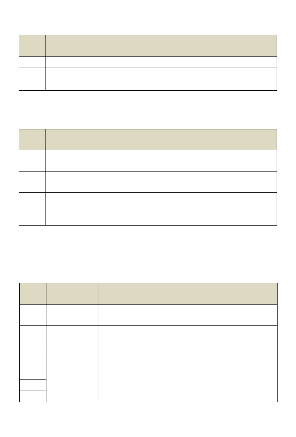
·J38 SPI Extension
Pin No. Pin Name Type Description
1 5V Power
Output Power Output,5V
2 SPI1_DO Output SPI Data Output
3 SPI1_DI Input SPI Data Input
4 SPI1_CSN Output SPI Chip Select
5 SPI1_CLK Output SPI Clock
6 GPIO Output/In
put IO Port, Reserved
7 GND Output SPI Clock Output
8 NC NC
Pin No. Pin Name Type Description
1 IO9 Input/Out
pu Reserved IO
2 IO8 Input/Out
pu Reserved IO
3 IO4 Input/Out
pu Reserved IO
4 IO6 Input/Out
pu Reserved IO
5 IO3 Input/Out
pu Reserved IO
6 IO5 Input/Out
pu Reserved IO
7 3V3 Input/Out
pu Reserved IO
8 SDA Input/Out
pu I2C Data, Reserved
9 SCL Output I2C Clock, Reserved
10 GND Ground Ground
11 URX2 Input Debug Interface, Reserved
12 URT2 Output Debug Interface, Reserved
Chapter 3 Interfaces
Signway Media Player Board SWH-5180 SPEC V2.0 15
·J42 MIC
Pin
No. Pin Name Type Description
1 MIC+ Input Microphone Input Positive Pole
2 MIC- Input Microphone Input Negative Pole
3 GND Ground Ground
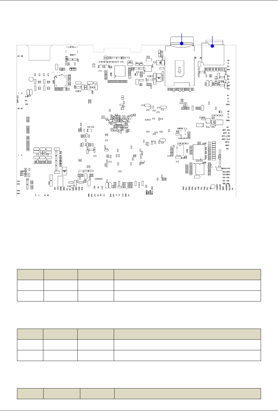
·J45 USB Extension
Pin
No. Pin Name Type Description
1 5V Power
Output Power Output,5V
2 D- Input\Out
put D- Signal
3 D+ Input\Out
put D+ Signal
4 GND Ground Ground
·JMP1 LCD Screen Pressure Selection Interface
JMP1 corresponds to the LCDVCC1 voltage selection on the CN5 socket
Pin
No. Pin Name Type Description
1 3.3V Power
Output Power Output,3.3V
3 5V Power
Output Power Output,5V
5 12V Power
Output Power Output,12V
2
LCDVCC1 Power
Output Screen Pressure Output4
6
Chapter 3 Interfaces
Signway Media Player Board SWH-5180 SPEC V2.0 16
·JMP2 EDP Screen Pressure Selection Interface
JMP2 corresponds to the EDP-VCC voltage selection on the J1 socket
·U8 MIPI Input/Output
Pin
No. Pin Name Type Description
1 5V Output 5V
3 5V Output 5V
5 GND Ground Ground
4 GND Ground Ground
5 BL_EN Output Backlight Enable
6 PWM Output Backlight Brightness Control
7 LCD_EN Output Enable
8 LCD_RST Output Reset
9 GND Ground Ground
10 MIPI_TX_D3N Output MIPI lane3 Output
11 MIPI_TX_D3P Output MIPI lane3 Output
12 GND Ground Ground
13 MIPI_TX_D2N Output MIPI lane2 Output
14 MIPI_TX_D2P Output MIPI lane2 Output
15 GND Ground Ground
16 MIPI_TX_CLKN Output MIPI Clock Output
Pin
No. Pin Name Type Description
1 3.3V Power
Output Power Output,3.3V
3 5V Power
Output Power Output,5V
5 12V Power
Output Power Output,12V
2
EDP-VCC Power
Output Screen Pressure Output4
6

Chapter 3 Interfaces
Signway Media Player Board SWH-5180 SPEC V2.0 17
Pin
No. Pin Name Type Description
17 MIPI_TX_CLKP Output MIPI Clock Output
18 GND Ground Ground
19 MIPI_TX_D1N Output MIPI lane1Output
20 MIPI_TX_D1P Output MIPI lane1Output
21 GND Ground Ground
22 MIPI_TX_D0N Output MIPI lane0Output
23 MIPI_TX_D0P Output MIPI lane0Output
24 GND Ground Ground
25 MIPI_TX/RX_D3N Output/Inp
ut MIPI lane3Output/Input
26 MIPI_TX/RX_D3P Output/Inp
ut MIPIlane3Output/Input
27 GND Ground Ground
28 MIPI_TX/RX_D2N Output/Inp
ut MIPI lane2Output/Input
29 MIPI_TX/RX_D2P Output/Inp
ut MIPI lane2Output/Input
30 GND Ground Ground
31 MIPI_TX/RX_CLKN Output/Inp
ut MIPI Clock
32 MIPI_TX/RX_CLKP Output/Inp
ut MIPI Clock
33 GND Ground Ground
34 MIPI_TX/RX_D1N Output/Inp
ut MIPI lane1Output/Input
35 MIPI_TX/RX_D1P Output/Inp
ut MIPI lane1Output/Input
36 GND Ground Ground
37 MIPI_TX/RX_D0N Output/Inp
ut MIPI lane0Output/Input
38 MIPI_TX/RX_D0P Output/Inp
ut MIPI lane0Output/Input
39 GND Ground Ground
40 MIPI_RST Output MIPI Reset
41 CIF_PDN Output IO Control, Reserved
42 CIF_CLK Output Clock Output, Reserved

Chapter 3 Interfaces
Signway Media Player Board SWH-5180 SPEC V2.0 18
Pin
No. Pin Name Type Description
43 I2C_SCL Output I2C Clock
44 I2C_SDA Input/出I2C Data
45 GND Ground Ground
46 GND Ground Ground
47 VCC15 Output 1.5V Power
48 VCC18 Output 1.8V Power
49 AVDD28 Output Simulation 2.8V
50 VCC28 Output 2.8V Power
·CN5 LVDS Signal Output
Pin
No.
Pin Name Type Description
1
LCDVCC1 Power
Output
LCD Screen Power Output,
3.3V/5V/12V(optional)
2
3
4
GND Ground Power Ground5
6
7 RXO0- Output Pixel0 Negative Data (Odd)
8 RXO0+ Output Pixel0 Positive Data (Odd)
9RXO1- Output Pixel1 Negative Data (Odd)
10 RXO1+ Output Pixel1 Positive Data (Odd)
11 RXO2- Output Pixel2 Negative Data (Odd)
12 RXO2+ Output Pixel2 Positive Data (Odd)
13 GND Ground Power Ground
14
15 RXOC- Output Negative Sampling Clock (Odd)
16 RXOC+ Output Positive Sampling Clock (Odd)
17 RXO3- Output Pixel3 Negative Data (Odd)
18 RXO3+ Output Pixel3 Positive Data (Odd)
19 RXE0- Output Pixel0 Negative Data ( Even )
20 RXE0+ Output Pixel0 Positive Data ( Even )
21 RXE1- Output Pixel1 Negative Data ( Even )

Chapter 3 Electrical Performance
Signway Media Player Board SWH-5180 SPEC V2.0 19
Pin
No.
Pin Name Type Description
21 RXE1+ Output Pixel1 Positive Data ( Even )
23 RXE2- Output Pixel2 Negative Data ( Even )
24 RXE2+ Output Pixel2 Positive Data( Even )
25 GND Ground Power Ground
26
27 RXEC- Output Negative Sampling Clock ( Even )
28 RXEC+ Output Positive Sampling Clock ( Even )
29 RXE3- Output Pixel3 Negative Data ( Even )
30 RXE3+ Output Pixel3 Positive Data ( Even )
31 GND Ground Power Ground
32
33 LCD_HSYNC Output Reserved
34 XN223_BLANK Output Reserved
35 LCD_VSYNC Output Reserved
36 LCD_CLK Input/出Reserved
37 RXO4- Output Pixel2 Negative Data ( Odd )
38 RXO4+ Output Pixel2 Positive Data (Odd )
39 RXE4- Output Pixel2 Negative Data ( Even )
40 RXE4- Output Pixel2 Positive Data ( Even )
·J2 TF Card Slot
·J9 SIM Card Slot
·J41 Place on 2 jumper caps when supply single 12V power
·U28 MINIPCIE slot, expandable 3G / 4G module
·RJ45 LAN
·HDMI_OUT 4KExternal HDMI signal Output, Max. 4K
·AU_OUT Audio Sound Output
·SW1 System forced upgrade button

Chapter 3 Interfaces
Signway Media Player Board SWH-5180 SPEC V2.0 20
·J24 Master IC USB OTG port, can be used for system upgrades;
access system; external USB device
·ANT5 WIFI/BT Antenna
·FCAP2 When the board is powered off, Power is supplied to the RTC
Real-Time Clock
Chapter 3 Interfaces
Signway Media Player Board SWH-5180 SPEC V2.0 21
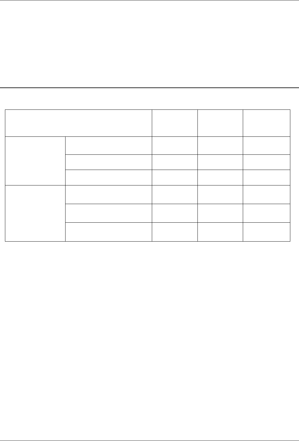
5Electrical Performance
Item Min Typical Max
Parameters
Voltage -- 12V --
Ripple -- -- --
Current -- TBD --
Environment
Relative Humidity -- -- 80%
Working Temperature 0℃ -- 40℃
Storage Temperature 0℃ -- 70℃