Navico BR24 FMCW WITH LINEAR FREQUENCY SWEEP User Manual FMCW Install cover indd
Navico Auckland Limited FMCW WITH LINEAR FREQUENCY SWEEP FMCW Install cover indd
UserManual.wiki
>
Navico
>
BR24 User Manual
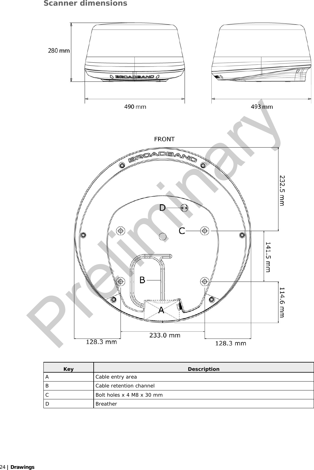
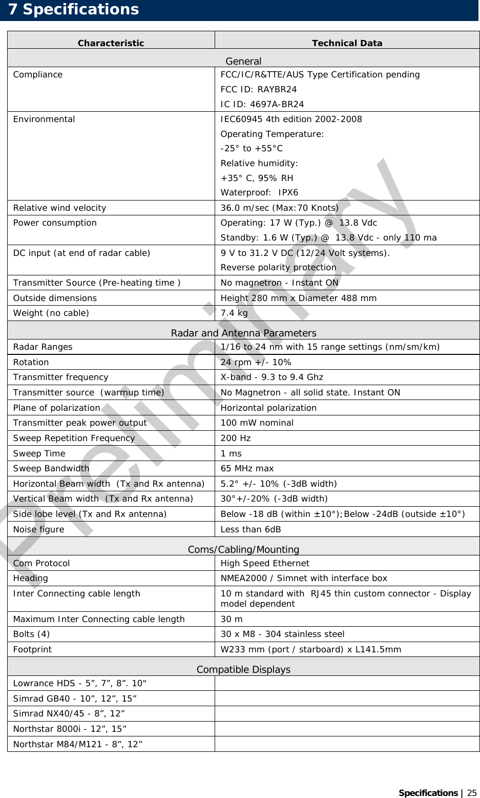
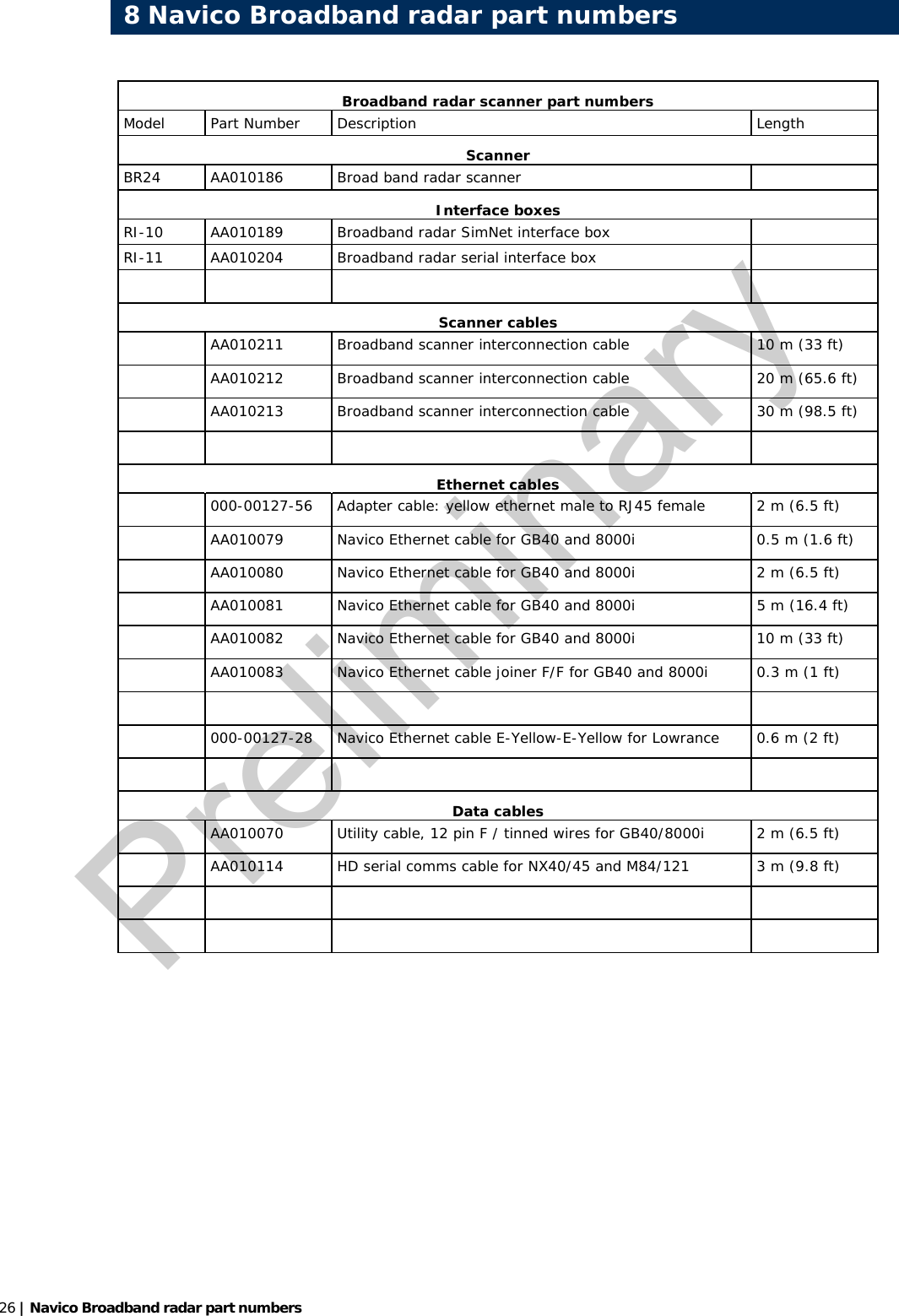
USERS MANUAL
Navigation menu
Upload a User Manual
Namespaces
Wiki Guide
HTML
PDF
Info
Views
User Manual
Discussion / Help
Navigation