Navico BR24 FMCW WITH LINEAR FREQUENCY SWEEP User Manual FMCW Install cover indd
Navico Auckland Limited FMCW WITH LINEAR FREQUENCY SWEEP FMCW Install cover indd
Navico >
USERS MANUAL

www.simrad-yachting.com
www.lowrance.com
www.northstarnav.com.
Brands by Navico - Leader in Marine Electronics
Installation
Manual
Navico Broadband Radar
BR-24
English Preliminary
Preliminary

Navico Radar Broadband Installation manual English, Doc.no. Preliniary
Preliminary

Preface | 1
FCC Statement
Note: This equipment has been tested and complies with the limits for a Class B digital device,
pursuant to Part 15 of the FCC Rules. These limits are designed to provide reasonable
protection against harmful interference in a normal installation. This equipment generates, uses
and can radiate radio frequency energy and, if not installed and used in accordance with the
instructions, may cause harmful interference to radio communications. However, there is no
guarantee that interference will not occur in a particular installation.
If this equipment does cause harmful interference to radio or television reception, which can be
determined by turning the equipment off and on, the user is encouraged to try to correct the
interference by one or more of the following measures:
• Reorient or relocate the receiving antenna.
• Increase the separation between the equipment and receiver.
• Connect the equipment into an output on a circuit different from that to which the receiver is
connected.
• Consult the dealer or an experienced technician for help.
• A shielded cable must be used when connecting a peripheral to the serial ports.
Industry Canada
Operation is subject to the following two conditions:
(1) this device may not cause interference, and
(2) this device must accept any interference, including interference that may cause undesired
operation of the device.
Refer also to the system specifications section.
CE Compliance
Navico New Zealand, declares that this Radar Processor is in compliance with the essential
requirements and other relevant provisions of Directive 1999/5/EC.
1 Preface
Preliminary
2 | Preface
Disclaimer
As Navico is continuously improving this product, we retain the right to make changes to the
product at any time which may not be reflected in this version of the manual. Please contact
your nearest distributor if you require any further assistance.
It is the owner’s sole responsibility to install and use the instrument and transducers in a
manner that will not cause accidents, personal injury or property damage. The user of this
product is solely responsible for observing safe boating practices.
NAVICO HOLDING AS. AND ITS SUBSIDIARIES, BRANCHES AND AFFILIATES DISCLAIM ALL
LIABILITY FOR ANY USE OF THIS PRODUCT IN A WAY THAT MAY CAUSE ACCIDENTS, DAMAGE
OR THAT MAY VIOLATE THE LAW.
Governing Language: This statement, any instruction manuals, user guides and other
information relating to the product (Documentation) may be translated to, or has been
translated from, another language (Translation). In the event of any conflict between any
Translation of the Documentation, the English language version of the Documentation will be
the official version of the Documentation.
This manual represents the product as at the time of printing. Navico Holding AS. and its
subsidiaries, branches and affiliates reserve the right to make changes to specifications without
notice.
Copyright © 2008 Navico Holding AS.
Warranty
The Navico warranty card is supplied as a separate document.
It is shipped with the product registration card.
In case of any queries, refer to Navico.com.
Feedback from you
Your feedback is important and helps Navico ensure that this manual is a valuable resource for
all marine technicians. E-mail your comments or suggestions about this manual to the following
address: tech.writing@navico.com
Preliminary
Preface | 3
Contents
1 Preface ........................................................................................................ 1
FCC Statement.............................................................................................1
Industry Canada...........................................................................................1
CE Compliance .............................................................................................1
Disclaimer ...................................................................................................2
Warranty.....................................................................................................2
Feedback from you .......................................................................................2
2 Introduction to the Navico Broadband radar system ................................... 5
What is Broadband radar?..............................................................................5
Radar system overview..................................................................................7
Warnings.....................................................................................................7
3 Install the radar........................................................................................... 8
Check the parts............................................................................................8
Choose the scanner location...........................................................................9
Mounting the scanner.................................................................................. 10
Mounting the radar interface box .................................................................. 11
4 Wiring the radar system ............................................................................12
Connect interconection cable to the scanner ...................................................12
Connect the interconnection cable to radar interface box..................................12
Connect power ........................................................................................... 14
Connect the Broadband radar to your display.................................................. 16
Lowrance HDS (U.S only)......................................................................................16
Lowrance HDS (Non U.S market) ...........................................................................16
GB40 .................................................................................................................16
8000i.................................................................................................................16
NX40 and NX 45..................................................................................................17
M84 and M121 ....................................................................................................17
Connecting a heading sensor........................................................................ 18
GB40 .................................................................................................................18
NX 40, NX45.......................................................................................................19
8000i NMEA 0183 ................................................................................................19
M-84 and M-121..................................................................................................20
5 Configure displays to use radar ................................................................. 21
Lowrance HDS radar setup...........................................................................21
Simrad GB40 / Northstar 8000i radar setup.................................................... 21
Simrad NX40/45 or Northstar M84/M121 radar setup.......................................22
Preliminary
4 | Preface
6 Drawings ................................................................................................... 23
Radar interface box..................................................................................... 23
Scanner dimensions....................................................................................24
7 Specifications ............................................................................................ 25
8 Navico Broadband radar part numbers ...................................................... 26
9 Maintenance ..............................................................................................27
Preliminary
Introduction to the Navico Broadband radar system | 5
What is Broadband radar?
The Navico Broad band radar uses FMCW (Frequency Modulated Continuous Wave) radar
technology
What is FMCW?
The current normal leisure radar generates microwave pulses with a thermionic device called a
magnetron. This ancient technology sends out bursts of high power microwave energy
periodically, and the radar detector listens to the echoes coming back from each pulse. As the
radar rotates these echoes are built into a 360 degree image.
FMCW radar is different:
Firstly it is solid state – i.e. the transmitter is a semiconductor device, not based on thermoinic
valve technology.
Secondly it transmits continuously, not in pulses and thirdly it measures the time of the echo
not by listening to a received pulse but by varying the frequency of the transmitted signal and
detecting the shift in frequency in the received echo. Hence FMCW – Frequency Modulated
Continuous Wave.
The building up of the image over 360 degrees and the processing of the radar data is the same
as for a magnetron radar.
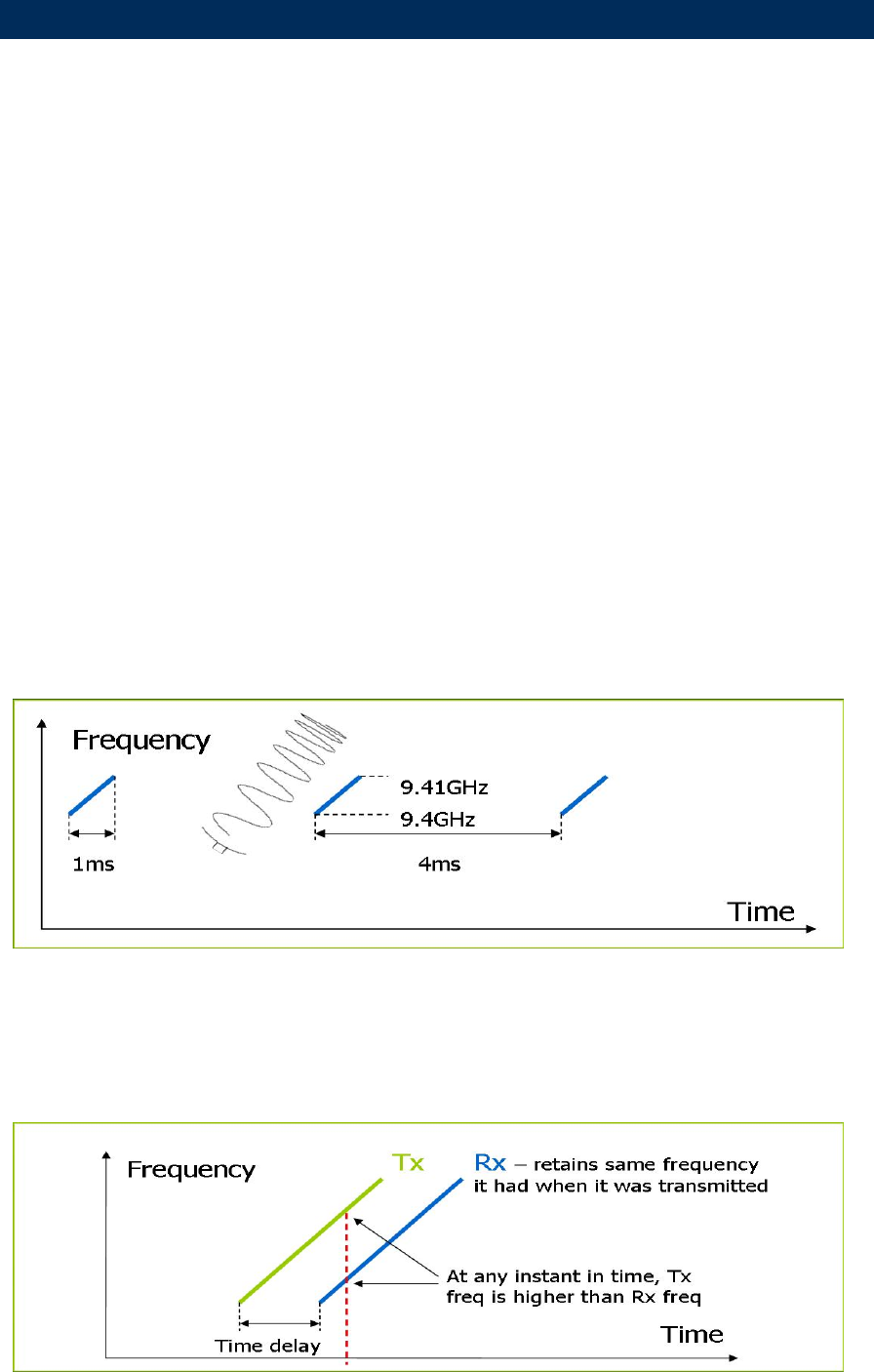
How does FMCW radar work?
FMCW = Frequency Modulated Continuous Wave
The scanner transmits a ‘rising tone’ (Tx wave) with linear increasing frequency. The wave
propagates out from the transmitter retaining the frequency it had when it was transmitted. If it
reflects off an object, it will return to the receiver, still at the frequency it had when originally
transmitted.
Meanwhile the transmitter continues to output an increasing frequency
2 Introduction to the Navico Broadband radar system
Preliminary
6 | Introduction to the Navico Broadband radar system
The difference in the currently transmitted and currently received frequencies, coupled with the
known rate of frequency increase, allows a time of flight to be calculated, from which distance is
calculated
Benefits of FMCW radar
Safer
• low energy emissions, similar to a cell phone
• more flexibility in placement on boat
• can run in anchorages and marinas
Short range performance
• Conventional radars can not see anything closer than 30 meters
• FMCW can see within a few meters of the boat
• See the objects that pose the greatest threat to your boat
Low power
• expands market to small boats and yachts
• easier install, lighter cabling
• great for yachts on ocean passage
Instant power-up
• Conventional radars take 2-3 minutes to heat up the filament: Safety – 2 minutes is a long
time if you are concerned about collision
• Convenience – switch it on and use it
Preliminary

Introduction to the Navico Broadband radar system | 7
Radar system overview
The Navico Broadband radar is a state of the art navigation aid providing outstanding radar
performance with out the limitations of conventional pulse radars such as dangerous high power
microwaves, Standby warm up time, high power consumption and large open arrays which is
what would be required to obtain the same image quality at shorter ranges . The Navico
Broadband radar as an effective range from 1/16 to 24 nm. and has an operating power
consumption of 17 W.
The system consists of radar scanner, an interface box and a interconnection cable. The scanner
is housed in a dome on is of similar size to most 2 kW radars on the market.
The interface box is used to connect displays and heading information. There are two models
(RI-10 and RI-11) depending on the display system used the main difference being one has a
SimNet connector for heading input (RI-10). The other interface box (RI-11) has a connector to
interface to RS422 displays and NMEA 0183 heading sensors. both interface boxes have a
Network connector to interface to Ethernet displays.
Note Lowrance HDS units sold in the USA do not require an interface box and the scanner
connects directly to the display or ethernet switch
Brand Model Radar interface
box used Radar
connection kit Data connection
protocol Chart
overlay MARPA
Lowrance HDS USA N/A Ethernet Yes* Yes**
Lowrance HDS R.O.W RI-11 Ethernet Yes* Yes**
Simrad GB40 RI-10
Ethernet Yes* Yes**
Northstar 8000i RI-11 Ethernet Yes* Yes**
Northstar 8000i + N2k RI-10 Ethernet Yes* YES**
Northstar M series RI-11 RS422 Yes* No
Simrad NX 40/45 RI-11
RS422 Yes* No
*For best chart overlay performance use a heading sensor. Course over ground can be used but
only when moving
** For MARPA it is essential to use a heading sensor with an out put speed of 10 hZ or faster
Warnings
Preliminary

8 | Install the radar
Installation includes:
• mechanical mounting
• electrical wiring
• configuring the display or network system to work with the radar
• adjusting the radar for proper performance
Don't take any shortcuts, and follow these instructions carefully!
This section explains how to:
• choose the correct location for the scanner
• install the scanner on a power boat or a yacht
• choose the correct location for the radar processor
• install the radar processor
Check the parts
NEED A BREAK DOWN OF KITS AND UNDER LYING PARTS
3 Install the radar
Preliminary
Install the radar | 9
Choose the scanner location
The radar's ability to detect targets depends greatly on the position of its scanner. The ideal
location for the scanner is high above the vessel's keel line where there are no obstacles.
A higher installation position increases the radar ranging distance, but it also increases the
minimum range around the vessel where targets cannot be detected.
When you're deciding on the location, consider the following:
• the length of the interconnection cable supplied with your radar is usually sufficient. If you
think you'll need a longer cable, consult your dealer before installation, because a longer
cable may reduce the performance of the radar.
• if the roof of the wheelhouse is the highest existing location, consider installing a radar mast
or a pedestal on which you can mount the scanner. You may also need to construct a
working platform for your own safety during installation and servicing work.
• if you mount the scanner on a pedestal or base, ensure that rain and sea spray can drain
away from it rapidly.
• if you locate the scanner on the mast, position it on the forward side so that there is a clear
view to the front of the vessel.
• the scanner is usually installed parallel to the line of the keel.
• ensure that the location site provides the scanner with a clear view of the front of the vessel.
DON'T DO THIS!
• DON'T install the scanner too high up, where its weight will alter the stability of the vessel
and cause degradation of the radar picture over short ranges.
• DON'T install the scanner close to lamps or exhaust outlets. The heat emissions may
damage the dome. Soot and smoke will degrade the performance of the radar.
• DON'T install the scanner close to the antennas of other equipment such as direction finders,
VHF antennas, GPS equipment and so on, because it may cause interference.
• DON'T install the scanner where a large obstruction (such as an exhaust stack) is at the
same level as the beam, because the obstruction is likely to generate false echoes and/or
shadow zones.
• DON'T install the scanner where it will be subjected to strong vibrations (such as a derrick
post) because these vibrations will degrade the performance of the radar.
Preliminary
10 | Install the radar
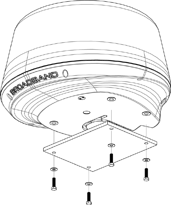
Mounting the scanner
• Use the supplied mounting template and tape it securely to the chosen location site.
• Before drilling, check that:
- you have oriented the mounting template correctly so that the front of the scanner
unit will face the front of the vessel
- the location site is not more than 15 mm (0.6") thick. If the location site is thicker use
longer bolts
Note: The bolts supplied are M8 x 30 mm x 4. If you need to use longer bolts make sure they
are 304 stainless steel and allow for 15 mm (0.6") of thread contact
• the location site allows the drain hole to empty.
• Drill the four holes where shown.
• Remove the mounting template,
• Connect the scanner interconnection cable (see "Connect the Broadband radar to your
display" page 16)
• Position the scanner carefully over the bolt holes so that they are aligned
• Place a spring washer then a plain washer onto each bolt, as shown.
• Screw each bolt into each drill hole from the under side of the location site, and tighten
securely
Preliminary
Install the radar | 11
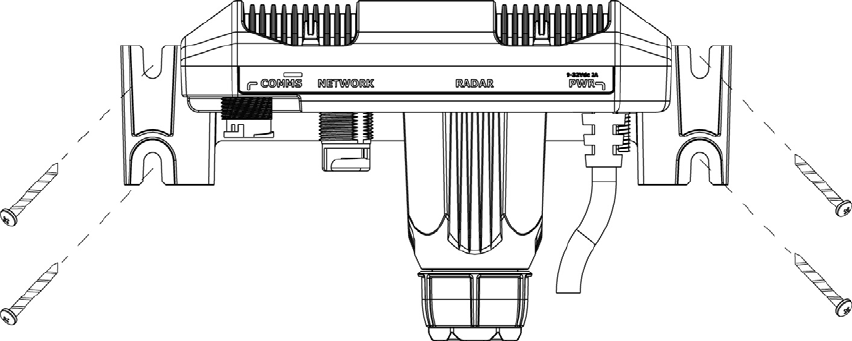
Mounting the radar interface box
• Install the radar interface box in a dry location away from spray, rain, drips and
condensation.
• The radar processor must be located where it can be easily connected to the ship's
ground, the scanner interconnection cable, a power source and the display or display
network.
• Allow enough room for cables to form a drip loop.
• Preferably mount the radar interface box on a vertical surface with cables exiting
downwards.
• Secure to the surface using the four mounting points
Preliminary

12 | Wiring the radar system
Connect interconection cable to the scanner
The scanner interconnection cable connects the scanner to the RI-10 or RI-11 interface box (or
Lowrance HDS U.S only). The cable connects to the scanner using a 14 pin connector.
Insert cable connector on to the male 14 pin plug on the scanner. take care to align the
connector correctly to avoid bending the pins. Secure the locking collar by rotating clockwise
Feed and secure the cable into the cable retention channel
Interconnection cable pin out
Pinout
Conn Wire color RJ45
1 Black Tinned wire
2 Red Tinned wire
3 Yellow Tinned wire
4 Drain Tinned wire
5 N/A N/A
6 Blue RJ45 Pin 4
7 White / Blue RJ45 Pin 5
8 white / Brown RJ45 Pin 7
9 Brown RJ45 Pin 8
10 White / Green RJ45 Pin 3
11 N/A N/A
12 White / Orange RJ45 Pin 1
13 Green RJ45 Pin 6
Scanner connector Cable connector
14 Orange RJ45 Pin 2
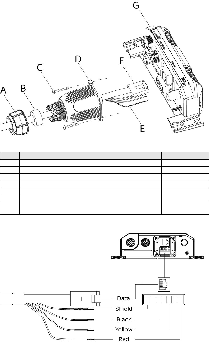
Connect the interconnection cable to radar interface box
• Remove the 4 phillips screws that secure the cable gland housing and disassemble
• slide the lock nut, gland washer, and glad housing on to the scanner cable
• connect power wires to the terminal strip
• connect the RJ45 data connector
• secure the gland housing to the interface box using the 4 screws
• Insert the gland washer into the gland housing
4 Wirin
g
the radar system
Preliminary
Wiring the radar system | 13
• screw the lock nut on to the gland housing
Key Description Part Number
A Lock nut
B Gland washer
C Screws x 4 M3x12mm phillips pan head SR000041-G
D Cable gland housing
E Power wires (see "Connect power" page 14)
F Radar data connector RJ45
G Radar interface box AA010204 (Serial)
AA010189 (Network)
Preliminary
14 | Wiring the radar system
Shortening the cable
It is not recommended to shorten the cable but if it is essential use the pin-out below to re-
terminate the RJ45 connector
RJ45 Connector
Pin Colour
1 White/Orange
2 Orange
3 White/Green
4 Blue
5 White/Blue
6 Green
7 White/Brown
8 Brown
RJ45 Connector 15 mm Heat shrink (10 mm dia)
Connect power
Before connecting power to the system:
• make sure the scanner has been installed and is secured
• make sure the scanner cable is connected to the scanner
• if using the Radar Interface Box make sure all connections have been made to the display
The radar system can operate on voltages of 9-32 V DC. The system requires a (+ V DC) to be
applied to the yellow remote power on wire in order to operate. This can be achieved by one of
three ways.
• Common the red and yellow wires together. Radar will power on when power is applied
• Install a switch that will provide power to the yellow wire. Radar will turn on when switch
is activated
• Connect to the yellow wire to a the external wake up of a suitable display. Radar will turn
on when display is turned on
For systems using a radar interface box
• Connect the red wire to power positive 9-32 V DC. Use a 5 amp fuse or breaker
• Connect the yellow wire to power source that will turn on the system (see above)
• Connect black to power negative
It is recommended where possible to connect the radar interface box to ships ground
Preliminary
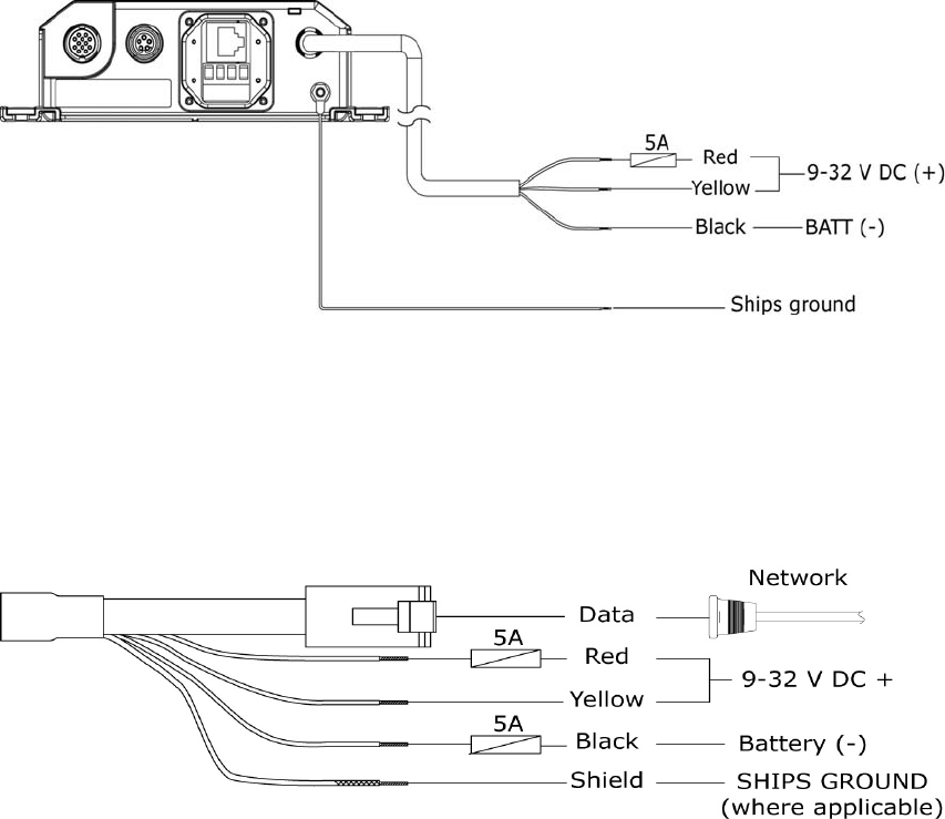
Wiring the radar system | 15
For systems that do not require a Radar Interface Box, connect power directly to the scanner
cable.
Note: Connect shield to ships ground if applicable or connect to battery negative
Preliminary
16 | Wiring the radar system
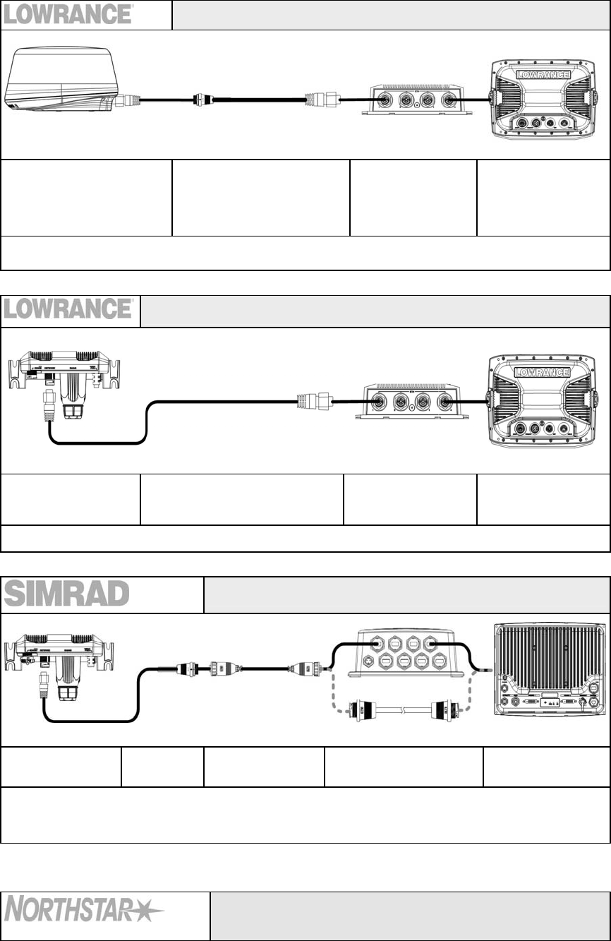
Connect the Broadband radar to your display
Lowrance HDS (U.S only)
Broadband scanner Adapter cable
000-0127-56 0.6 m (2 ft)
Optional 5 port
switch HDS Display
ENET Port
Lowrance broadband in the US market does not require a Radar interface box. the scanner connects
directly the display or ethernet switch via the adaptor cable
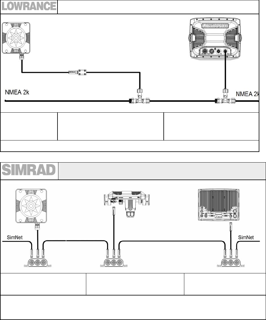
Lowrance HDS (Non U.S market)
RI-11 NETWORK port Ethernet cable Lowrance 5 port
ethernet switch HDS Display
ENET port
GB40
RI-10 NETWORK
port Adaptor
cable Ethernet cable 8 port Ethernet linker
or cross-over cable NETWORK port
Connects to GB40 system via ethernet. Connect a GB40 ethernet cable in between 8 port
ethernet linker (or crossover cable) and supplied adaptor cable. Use only GB40 8000i
ethernet cables
8000i
12" Display processor or Black box processor
Preliminary
Wiring the radar system | 17
RI-11 NETWORK
port Adaptor cable
000-0127-56
Ethernet cable
AA000056
8 port Ethernet linker
(or cross-over cable)
AA010009
(AA010084
NETWORK port
Connects to 8000i system via ethernet. Connect 8000i ethernet cable in between 8 port linker (or
crossover cable) and supplied adaptor cable.
NX40 and NX 45
M84 and M121
RI-11
COMMS port
Data cable
AA010114 3m (9.8 ft)
NX or M series
RADAR port
Preliminary
18 | Wiring the radar system
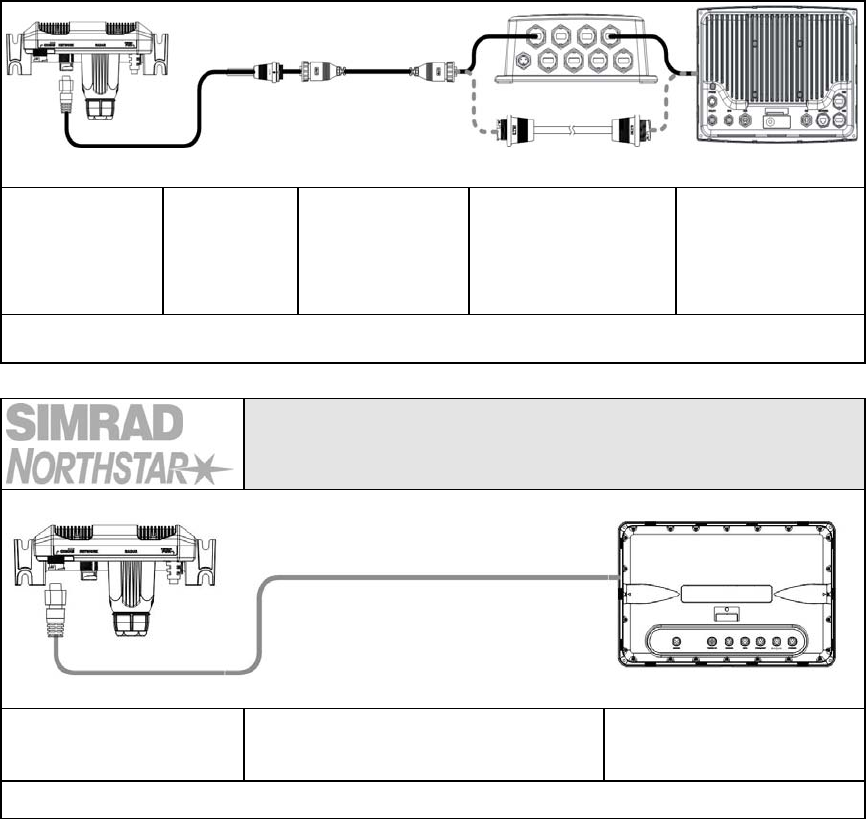
Connecting a heading sensor
SimNet heading
sensor
FC40 or RC42
SimNet to NMEA converter HDS
NMEA 2K port
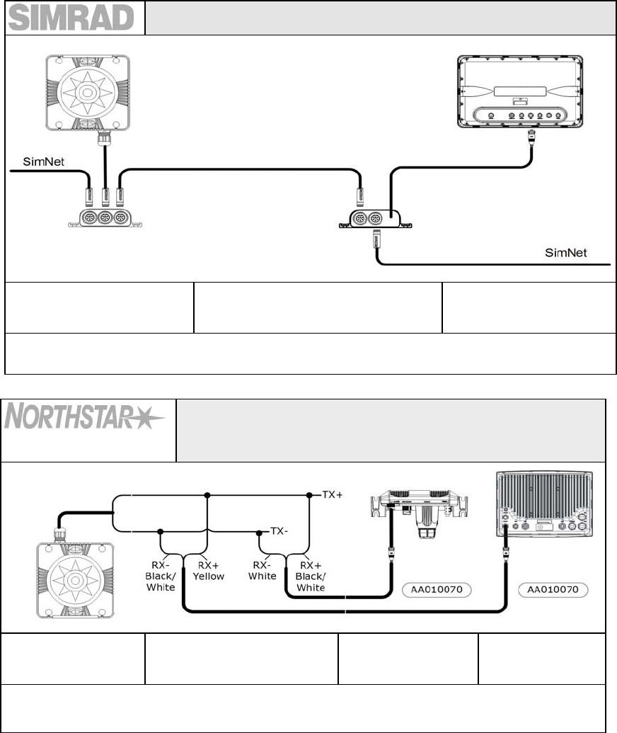
GB40
SimNet heading sensor
FC40 or RC42
RI-10
SimNet port
GB40 Navcomputer
SimNet port
For MARPA functionality on GB40 heading information at 10 Hz needs to be sent to both the RI-11 and the
GB40 NavComputer. Connect a SimNet drop cable from the Simnet backbone to the RI-11 and connect to
the COMS port (SimNet connector)
Preliminary
Wiring the radar system | 19
NX 40, NX45
SimNet heading sensor
FC40 or RC42
AT40 or AT45 SimNet to NMEA 0183
converter NX 40 or NX45
GPS port
For accurate radar chart overlay a heading sensor on the SimNet backbone passes thought the AT40 or
AT45 which connects to the GPS port on the NX display
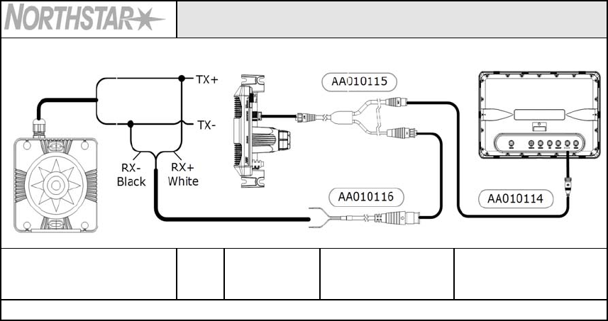
8000i NMEA 0183
12" Display processor, Black box processor, Simrad GB40 not using a
SimNet heading sensor
NMEA0183 Heading
Sensor Junction Box RI-11
COMMS port
8000i navcomputer
Utility port
For MARPA functionality, heading information at 10 Hz needs to be sent to both the RI-11 and the 8000i
master navcomputer. Use the 12 pin cable AA010070 cable from both units to a junction box to share
the same heading source.
Preliminary
20 | Wiring the radar system
M-84 and M-121
NMEA0183 heading sensor Juncti
on box RI-11
COMMS port
Connection kit
AA010112
M-84 or M121 Display
Radar port
For accurate radar overlay use an NMEA0183 heading sensor. Use supplied connection kit
Preliminary

Configure displays to use radar | 21
Setup and configuration of the Broadband radar has been simplified compared to traditional
pulse radars. There is no warm up time or burn in required. there is no "main bang" setup. The
only adjustment needed is to
• Set the scanner height: This is to help the radar calculate for sea clutter
• Adjust the heading marker. This is to align with the heading marker on the screen with
the center line of the vessel, this will compensate for any slight misalignment of the
scanner during installation. Any inaccuracy will me evident when using MARPA or chart
overlay.
Lowrance HDS radar setup
To commission the radar using Lowrance HDS. Set the bearing alignment and antenna height.
Enter radar installation by pressing Menu > Settings > Radar > Installation.
To set the antenna height
• Use the up / down arrows to select antenna height. Use the Left / Right arrows to select
the antenna height. The value will represent the antenna height in the units that have
selected such as feet ot meters.
To start the radar
• Press pages > Radar > Radar State. Use Cursor to edit the radar state. Select transmit to
activate the radar
To adjust the bearing alignment
Use the up / down arrows to select bearing alignment. Use the Left / Right arrows to adust bring
the heading line on the screen to represent the actual heading of the boat. point the boat to the
end of a head land or peninsular. adjust the bearing alignment so th heading line touches the
end of the same head land or peninsular
Simrad GB40 / Northstar 8000i radar setup
To Set antenna height
• Select Pages (Display 8000i) > Setup > Radar.
• Press edit and key in the height of the scanner in feet or meters depending on system
units setting
• Select Return
To Transmit
• From the radar page select Radar Mode
• Select transmit
To change the radar bearing alignment:
• Select Pages (Display 8000i). If you:
- don't have a page that shows the Radar screen in one pane and the Chart screen in
the other pane, edit or create a page that shows these two screens.
- do have a page that shows the Radar screen in one pane and the Chart screen in the
other, select it.
• Check that the Chart screen has the Radar Overlay turned On.
• Select the Radar pane so that it becomes the active pane. If you can't see the Adjust
Radar button, select Return.
5 Confi
g
ure displays to use radar
Preliminary

22 | Configure displays to use radar
• Select Adjust Radar, then select Installation.
• The Bearing Alignment button shows the current setting. Select it to change the setting.
Use the Up and Down buttons to move the radar image one degree at a time, until the
radar overlay is aligned with the chart.
• Select OK.
• Select Return.
Simrad NX40/45 or Northstar M84/M121 radar setup
When the radar is enabled, it will turn on, warm up, and enter standby mode.
To enable the radar functionality:
• Press Setup (NX) or menu twice to display the Setup menu, then select system
• Set Radar to .
Zero bearing
Adjust this on a chart window with the radar overlay on.
• Press Menu twice > Radar > Installation
• Select Zero bearing then use the arrow keys to enter the new bearing angle.
Antenna height
• Press Menu twice > Radar > Installation
• Select Antenna height then enter the height of the antenna above sea level.
Preliminary
Drawings | 23
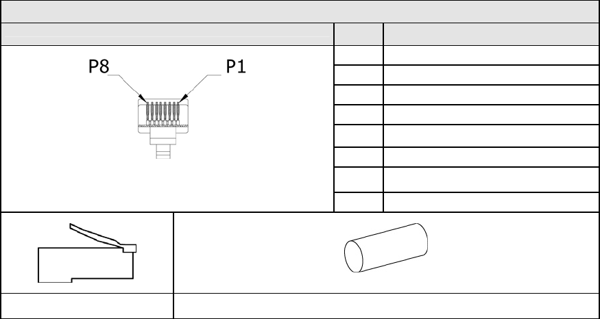
Radar interface box
6 Drawin
g
s
Preliminary
24 | Drawings
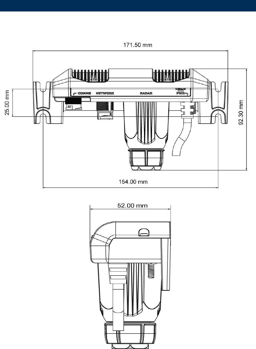
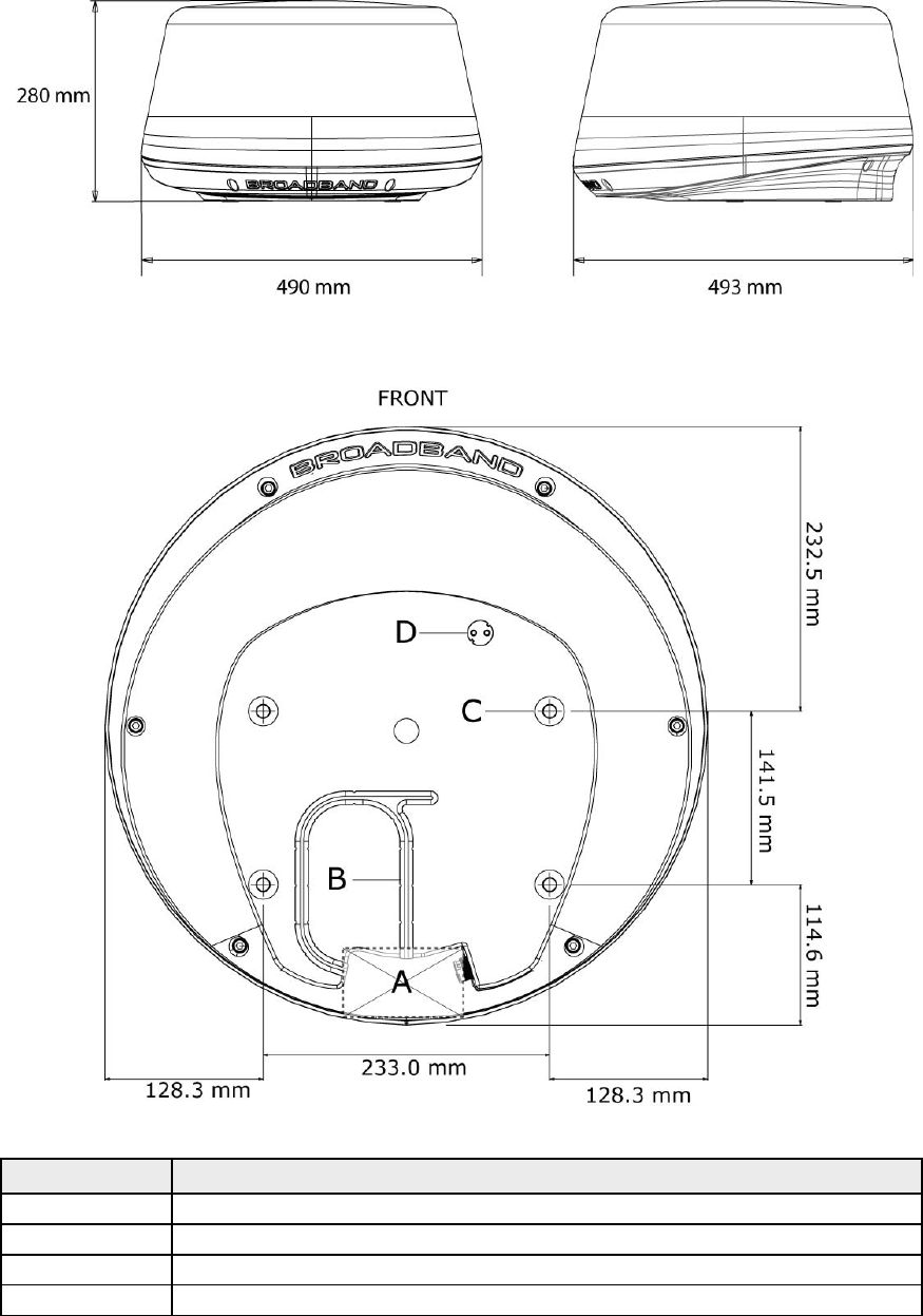
Scanner dimensions
Key Description
A Cable entry area
B Cable retention channel
C Bolt holes x 4 M8 x 30 mm
D Breather
Preliminary

Specifications | 25
Characteristic Technical Data
General
Compliance FCC/IC/R&TTE/AUS Type Certification pending
FCC ID: RAYBR24
IC ID: 4697A-BR24
Environmental IEC60945 4th edition 2002-2008
Operating Temperature:
-25° to +55°C
Relative humidity:
+35° C, 95% RH
Waterproof: IPX6
Relative wind velocity 36.0 m/sec (Max:70 Knots)
Power consumption Operating: 17 W (Typ.) @ 13.8 Vdc
Standby: 1.6 W (Typ.) @ 13.8 Vdc - only 110 ma
DC input (at end of radar cable) 9 V to 31.2 V DC (12/24 Volt systems).
Reverse polarity protection
Transmitter Source (Pre-heating time ) No magnetron - Instant ON
Outside dimensions Height 280 mm x Diameter 488 mm
Weight (no cable) 7.4 kg
Radar and Antenna Parameters
Radar Ranges 1/16 to 24 nm with 15 range settings (nm/sm/km)
Rotation 24 rpm +/- 10%
Transmitter frequency X-band - 9.3 to 9.4 Ghz
Transmitter source (warmup time) No Magnetron - all solid state. Instant ON
Plane of polarization Horizontal polarization
Transmitter peak power output 100 mW nominal
Sweep Repetition Frequency 200 Hz
Sweep Time 1 ms
Sweep Bandwidth 65 MHz max
Horizontal Beam width (Tx and Rx antenna) 5.2° +/- 10% (-3dB width)
Vertical Beam width (Tx and Rx antenna) 30°+/-20% (-3dB width)
Side lobe level (Tx and Rx antenna) Below -18 dB (within ±10°);Below -24dB (outside ±10°)
Noise figure Less than 6dB
Coms/Cabling/Mounting
Com Protocol High Speed Ethernet
Heading NMEA2000 / Simnet with interface box
Inter Connecting cable length 10 m standard with RJ45 thin custom connector - Display
model dependent
Maximum Inter Connecting cable length 30 m
Bolts (4) 30 x M8 - 304 stainless steel
Footprint W233 mm (port / starboard) x L141.5mm
Compatible Displays
Lowrance HDS - 5”, 7”, 8”. 10"
Simrad GB40 - 10”, 12”, 15”
Simrad NX40/45 - 8”, 12”
Northstar 8000i - 12”, 15”
Northstar M84/M121 - 8”, 12”
7 Specifications
Preliminary

26 | Navico Broadband radar part numbers
Broadband radar scanner part numbers
Model Part Number Description Length
Scanner
BR24 AA010186 Broad band radar scanner
Interface boxes
RI-10 AA010189 Broadband radar SimNet interface box
RI-11 AA010204 Broadband radar serial interface box
Scanner cables
AA010211 Broadband scanner interconnection cable 10 m (33 ft)
AA010212 Broadband scanner interconnection cable 20 m (65.6 ft)
AA010213 Broadband scanner interconnection cable 30 m (98.5 ft)
Ethernet cables
000-00127-56 Adapter cable: yellow ethernet male to RJ45 female 2 m (6.5 ft)
AA010079 Navico Ethernet cable for GB40 and 8000i 0.5 m (1.6 ft)
AA010080 Navico Ethernet cable for GB40 and 8000i 2 m (6.5 ft)
AA010081 Navico Ethernet cable for GB40 and 8000i 5 m (16.4 ft)
AA010082 Navico Ethernet cable for GB40 and 8000i 10 m (33 ft)
AA010083 Navico Ethernet cable joiner F/F for GB40 and 8000i 0.3 m (1 ft)
000-00127-28 Navico Ethernet cable E-Yellow-E-Yellow for Lowrance 0.6 m (2 ft)
Data cables
AA010070 Utility cable, 12 pin F / tinned wires for GB40/8000i 2 m (6.5 ft)
AA010114 HD serial comms cable for NX40/45 and M84/121 3 m (9.8 ft)
8 Navico Broadband radar part numbers
Preliminary

Maintenance | 27
Clean the radome using soapy water and a soft cloth. avoid using abrasive cleaning products.
Do not use solvents such as gasoline, acetone, M.E.K etc. as this will damage the dome surface
Upgrading Firmware
9 Maintenance
Preliminary

Navico Broadband Radar BR-24 Installation manual English, Doc.no. Preliniary