Nedap N V INVEXS170 Inductive Proximity Card Reader User Manual manual
N. V. Nederlandsche Apparatenfabriek NEDAP Inductive Proximity Card Reader manual
Contents
- 1. quick start guide
- 2. manual
manual
Date : 23 February 2012 Version 5
This information is furnished for guidance, and with no guarantee as to its accuracy or completeness; its publication conveys no licence under any patent or other right,
nor does the publisher assume liability for any consequence of its use; specifications and availability of goods mentioned in it are subject to change without notice; it is
not to be reproduced in any way, in whole or in part, without the written consent of the publisher.
© Nedap N.V., IDEAS P.O. Box 103 NL-7140 AC GROENLO The Netherlands
Page 1 of 4
Part.no.: 5265800
Invexs 170 readers
Mifare Nedap dual technology readers
GENERAL
The Invexs 170 reader series is capable of reading
(simultaneously) Nedap, Mifare and DESFire credentials due to
its dual reader technology. The Invexs can read Mifare,
DESFire and Nedap cards, and is equipped with keypad and /
or a display.
The Invexs output can be set to either Wiegand, XS RF
modulation or RS485 protocol (plain or encrypted)
Functionality and output are determined by the configuration of
the Invexs reader. The configuration is defined using the
programm AEreco, and deployed by the configuration card or
via AEmon. (More information about configurations can be
found in ConvexsInvexs_InstallGuide_E.)
Three LED’s (red, green, blue) and beeper are included (display version has no LED). Ciphers of the
keypad versions light up after activation, so when not active the ciphers are not visible.
Back panel is available in two colours, black and white (e.g. MNK170B, MNK170W)
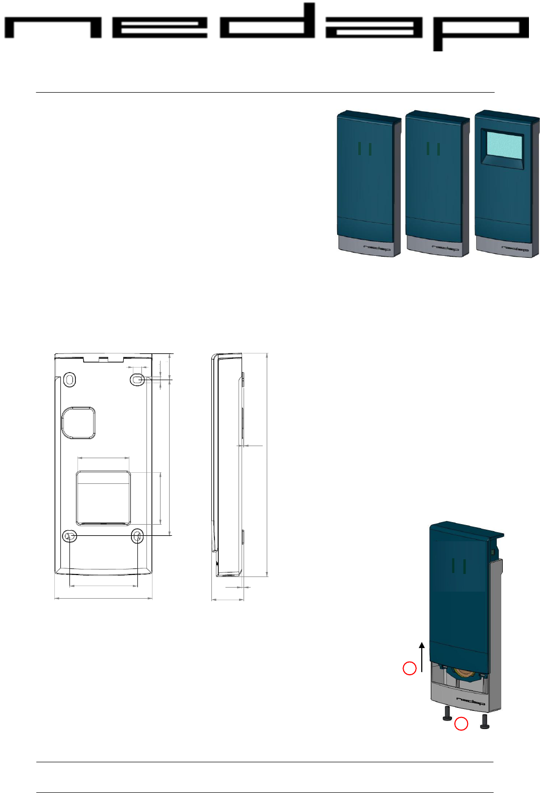
DIMENSIONS
MOUNTING PROCEDURE INVEXS
For mounting the Invexs, the back plane must be placed on the wall first.
For removing the back plane from the Invexs, unscrew the two screws (1) at
the bottom of the Invexs and push the front cover up (2). Mount the back
plane using the 4 holes.
Connections must be made on the connector on the backside of the front.
After making the connections, replace the front and tighten up the two screws
at the bottom of the Invexs.
®
Installation sheet
75.2
52
40
6.8
4.8
20.3
120
8
40
170.5
24.5
1.5
0.5
Dimensions: 171 x 75 x 25 mm.
4 mounting holes available at 52 x
120 mm
Cable outlet: 40 x 40 mm
1
2
3
4
5
6
7
8
9
C
0
E
Un screw
Push up
1
2
1
2
3
4
5
6
7
8
9
C
0
E
1
2
3
4
5
6
7
8
9
C
0
E
Invexs 170 readers
© Nedap N.V. Invexs 170 readers Installation sheet
Page 2 of 4
R
GND
UL*/NA* / BEEP
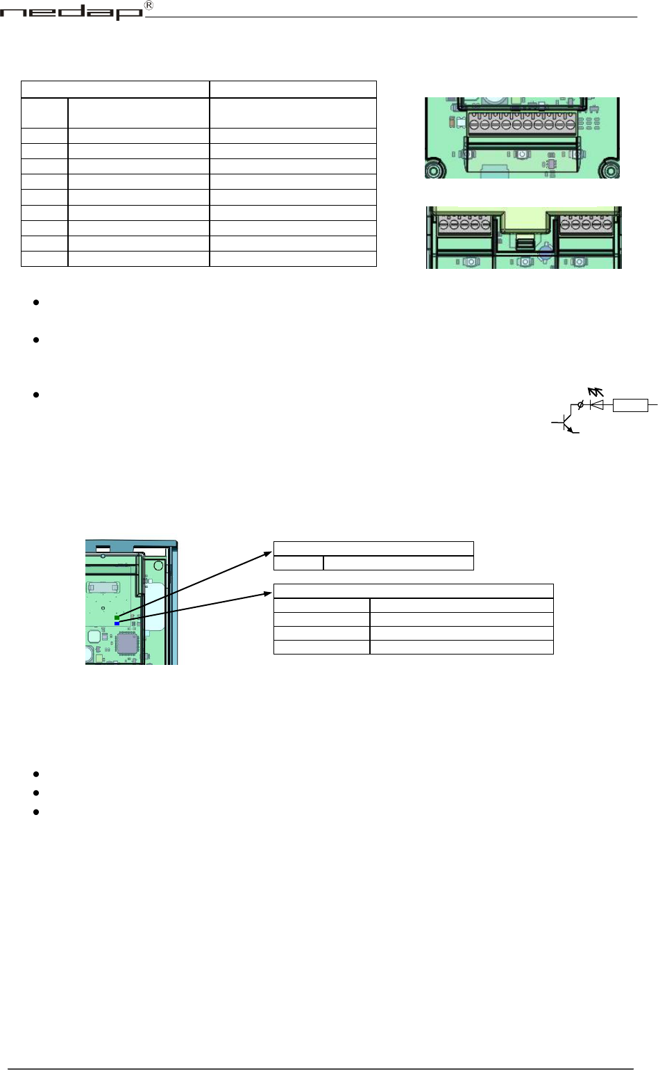
CONNECTIONS
Invexs is not hot-swappable, so when making or changing connections power must be switched Off.
Remark:
Cable shield must be connected to Power GND of Convexs (A2) and GND of external device
(or metal case).
If connected to a 120kHz RF device (AEOS Nedap reader AEpack or XS device) the power is
supplied via the Convexs adapters (AX1014 for AEpacks, AB350 for XS devices). Existing
antenna cabling can then be reused for connecting the ConveXS.
UL*,NA* and BEEP are Open Collector to GND.
If the Convexs adapters are used, the original UL and NA signals are
converted to the UL* and NA*.
LED INDICATORS INSIDE
There are two LED’s available: Blue for Status (of application), Green for Identification (both visible
through two small holes at the back side)
LED INDICATORS FRONT
At the front a three colour LED is positioned at the middle of the Invexs
Depending of the used configuration the function of these LED’s can differ:
Green LED: Card is been authorised (UL led)
Red LED: Card is not authorised (NA led), controller is stand-by
Blue LED:
Blinks fast: No configuration is availabele at this Invexs (present Configuration
card or load Configuration first).
Continuously ON: Determined by configuration: E.g. Reader stand-by.
(Blue LED is activated if UL is OFF and NA is more than 1 sec OFF)
Remark:
Function of LED’s and Beeper is controlled by used application settings of Invexs. Green and Red
LED can be controlled by hardware signals (Connector 8 and 10) or RS485NR, Blue LED
indirectly by UL and NA, if this setting is activated (configuration).
Beeper can be controlled by hardware signal (Connector 7), RS485NR or software (configuration).
Invexs
Function
1
Power /
XSMOD
Power in (10-30VDC) /
XS modulator (120kHz)
2
POWER GND/Shield
Power Ground
3
A (-)
RS485
4
B (+)
RS485
5
D0
Wiegand Data 0
6
D1
Wiegand Data 1
7
BEEP
Beep input
8
UL*
UL led input
9
GND
Led Common Ground
10
NA*
NA led input
1
10
1
10
5
1
6
1
Invexs with display
Invexs without display
ID (green)
Blinking
Card detected
ST: STATUS (blue)
Slow blinking
Application running (operating)
Fast blinking
Downloading or error during loading
2 short flashes
Application present but not active
3 short flashes
No application present
Invexs 170 readers
© Nedap N.V. Invexs 170 readers Installation sheet
Page 3 of 4
FIRMWARE
Pay attention that the firmware loaded in the Invexs together with the Invexs type and configuration
determines functionality and protocols. For the Invexs with screen contact Nedap.
Default (from factory) the Invexs handles the credentials on several ways simultaneously:
XS cards as: RS485NR, RF badge
Mifare cards (CSN) as: RS485NR, RF data
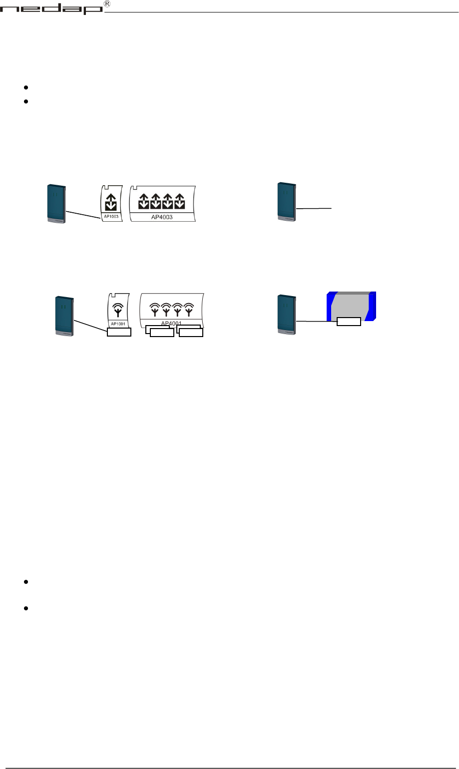
SYSTEM CONFIGURATIONS (how to connect Invexs readers)
Remark: Configurations can be determined by using the configuration card.
Attention: Check the ConvexsInvexs_InstallationGuide chapter 8 (Available reader Firmware) for the
compatibility for the used readers.
TAMPER SWITCH
This tamper switch is an optical device, which is triggered by the amount of light. Depending on the
applied configuration the result of activating the tamper switch can differ.
BEEPER INDICATIONS
Beeper is also used for indication of loading the configuration:
High sound beep (‘happy sound’): Configuration is loaded correct, second high sound beep
indicates that this configuration can be used with this Invexs
Low sound beep (‘unhappy sound’): Configuration is not correct loaded or no configuration
available at startup
Invexs uses existing antenna cabling
(Coax + 3*0,25qmm for LED’s).
On each AEpack-RF interface an AX1014
must be added. Connections: see AX1014
RF interface AEpacks
Accessor III /
SimpleXS
AX1014
AX1014
AX1014
AX1014
AX1014
AB350
RF interface XS systems
Invexs uses existing antenna cabling
(Coax + 3*0,25qmm for LED’s).
On each XS reader-RF interface an AB350
must be added. Connections: see AB350
To APx003 readers with RS485 special encrypted
protocol. (LED’s, Beeper, Keys and Display are
controlled over the RS485 communication)
AEOS RS485 interface
- Third party systems
- AEOS Wiegand
Wiegand interface
Wiegand output connected to Third party systems (or
to AEOS Wiegand interfaces). LED’s andBeeper are
controlled by hard wiring. (PINcode possible)
1
2
3
4
5
6
7
8
9
C
0
E
1
2
3
4
5
6
7
8
9
C
0
E
..--. ~ c:=Ii::3
FI®_R
-=In::,v..:.;e;;.:x""s:...1"-7'-'O'-r::..;:e:..::a:;.=d;.::.er=s
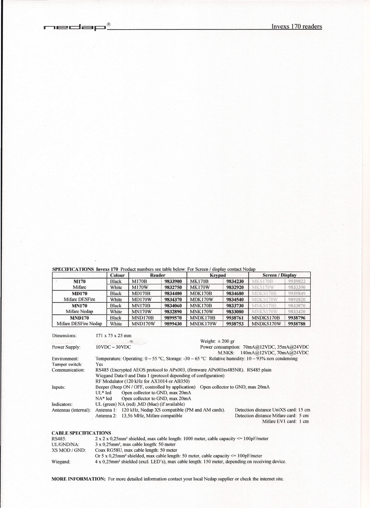
SPECIFICATIONS Invexs 170 Product numbers see table below: For Screen / dis la contact Neda
Colour Reader Ke ad Screen / Dis la
M170 Black M170B 9833900 MK170B 9834230 MKS I 70B 9939822
Mifare Wbite MI70W 9832750 MK170W 9832920 MKS 170W 9833390
MD170 Black MD170B 9834400 MDK170B 9834680 MDKSI70B 9939849
MifareDESFrr~e __ _+~W~h~it~e--~MD~I~7~OW~--~9~83~4~3~7~0_+~MD~K~17~0~W~~~9~8~3~45~4~0~~M~D~K~S~I~70~W~~~98~9~1~8~20~
MN170 Black MNI70B 9834060 MNK170B 9833730 MNKS170B 9833870
NtifareNedap ~W~h~it~e--~MN~I~7~OW__ --~9~83~2~8~9~0-+~~~~17~O_VV__ ~~9~8~3~30~8~0~~M--N-K~S~17-0~W--~~98~3~3~4~20~
MND170 Black MND170B 9899570 MNDK170B 9938761 MNDKS170B 9938796
Ntifare DESFire Ne=-=d=a!:..p_L~VVh~it~e__ L.:.:MND=::..:1~7..::0.:.:vv'---'-i..:::9~89::..:9:...:4:.:::3~0_L~MND:::::...:::::;K:=.17:..::0:...:w-'---'-i~9:..::9:.:::3:::.87.:..:5::::3:....J.-'MND=.:=K::::Sc:.l.:...:70,,-,W,,----,---,,-99::..:3:.::8:..:.7::::88,,----,
Dimensions: 171 x 75 x25 mm
Power Supply:
Weight:
±
200 gr
Power consumption: 70mA@12VDC, 35mA@24VDC
M.NKS: 140mA@12VDC, 70mA@24VDC
Temperature: Operating: 0 - 55°C, Storage: -30 - 65 °C Relative humidity: 10 - 93% non condensing
Yes
RS485 (Encrypted AEOS protocol to APx003, (firmware APx003rs485NR). RS485 plain
Wiegand Data 0 and Data I (protocol depending of configuration)
RF Modulator (120 kHz for AXI014 or AB350)
Beeper (Beep ON / OFF, controlled by application) Open collector to GND, max 20mA
UL
*
led Open collector to GND, max 20mA
NA
*
led Open collector to GND, max 20mA
UL (green) NA (red) ,MD (blue) (if available)
Antenna 1: 120 kHz, Nedap XS compatible (PM and AM cards).
Antenna 2: 13,56 MHz, Mifare compatible
Detection distance UniXS card: 15 cm
Detection distance Mifare card: 5 em
Mifare EY1 card: I em
IOVDC - 30VDC
Environment:
Tamper switch:
Communication:
Inputs:
Indicators:
Antennas (internal):
CABLE SPECIFICATIONS
RS485: 2 x 2 x 0,25mm' shielded, max cable length: 1000 meter, cable capacity <= 100pF/meter
ULlGND/NA: 3 x 0,25mrn', max cable length: 50 meter
XS MOD / GND: Coax RG58U, max cable length: 50 meter
Or 5 x 0,25mm' shielded, max cable length: 50 meter, cable capacity <= 100pF/meter
Wiegand: 4 x 0,25mm' shielded (excl. LED's), max cable length: ISO meter, depending on receiving device.
MORE INFORMATION: For more detailed information contact your local Nedap supplier or check the internet site.
FCC ID: CGDINVEXS170 and IC: 1444A-INVEXS170
Compliance statements (part15.19)
This device complies with part 15 of the FCC Rules and to RSS210 of Industry Canada.
Operation is subject to the following two conditions:
(1) this device may not cause harmful interference, and
(2) this device must accept any interference received, including interference that may cause undesired operation.
Cet appareil se conforme aux normes RSS210 exemptés de license du Industry Canada. L'opération est soumis
aux deux conditions suivantes:
(1) cet appareil ne doit causer aucune interférence, et
(2) cet appareil doit accepter n'importe quelle interférence, y inclus interférence qui peut causer une opération
non pas voulu de cet appareil.
Warning (part15.21)
Changes or modifications not expressly approved by party responsible for compliance could void the user’s
authority to operate the equipment.