Nedap N V SFSB Data Transmission System applied with a Sensor Bridge for lamps User Manual 20110223 Manual Nedap acsens4
N. V. Nederlandsche Apparatenfabriek NEDAP Data Transmission System applied with a Sensor Bridge for lamps 20110223 Manual Nedap acsens4
Contents
- 1. User manual 01
- 2. User manual 02
User manual 02
Option for Nedap Luxon wireless light control system
The Sensor Bridge is introduced to add commercially available sensors to the Nedap Luxon light control system.
Once installed the Sensor Bridge is part of the Senzafil Mesh Network.
Sensor data is transferred by this RF network to minimize wiring efforts.
Amongst the validated sensors you will find sensors to detect light level, movement or room occupancy.
Now it is easy to add sensing capabilities to your Luxon E-series light control system to save more energy.
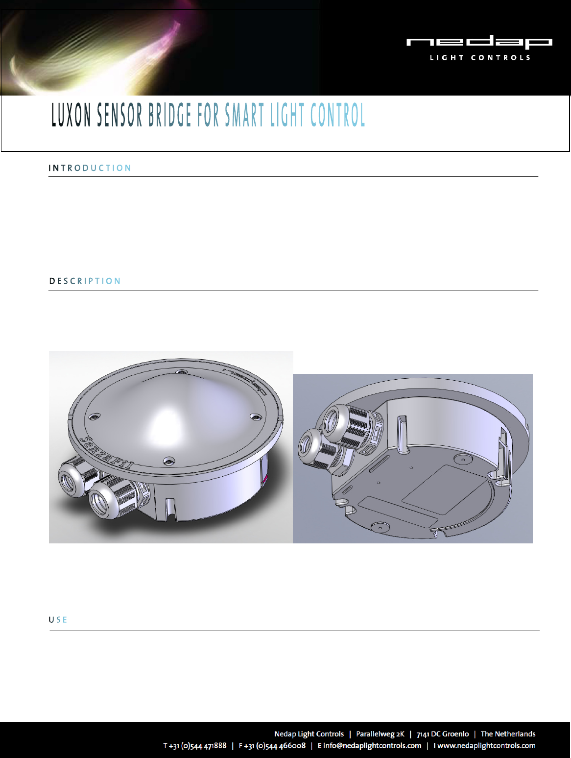
The Luxon Sensor Bridge consists two main parts:
The dome with the RF electronics and microcontroller
The base is used for cable connections for power and sensor.
Figure 1: Luxon Sensor Bridge, version for surface mounting
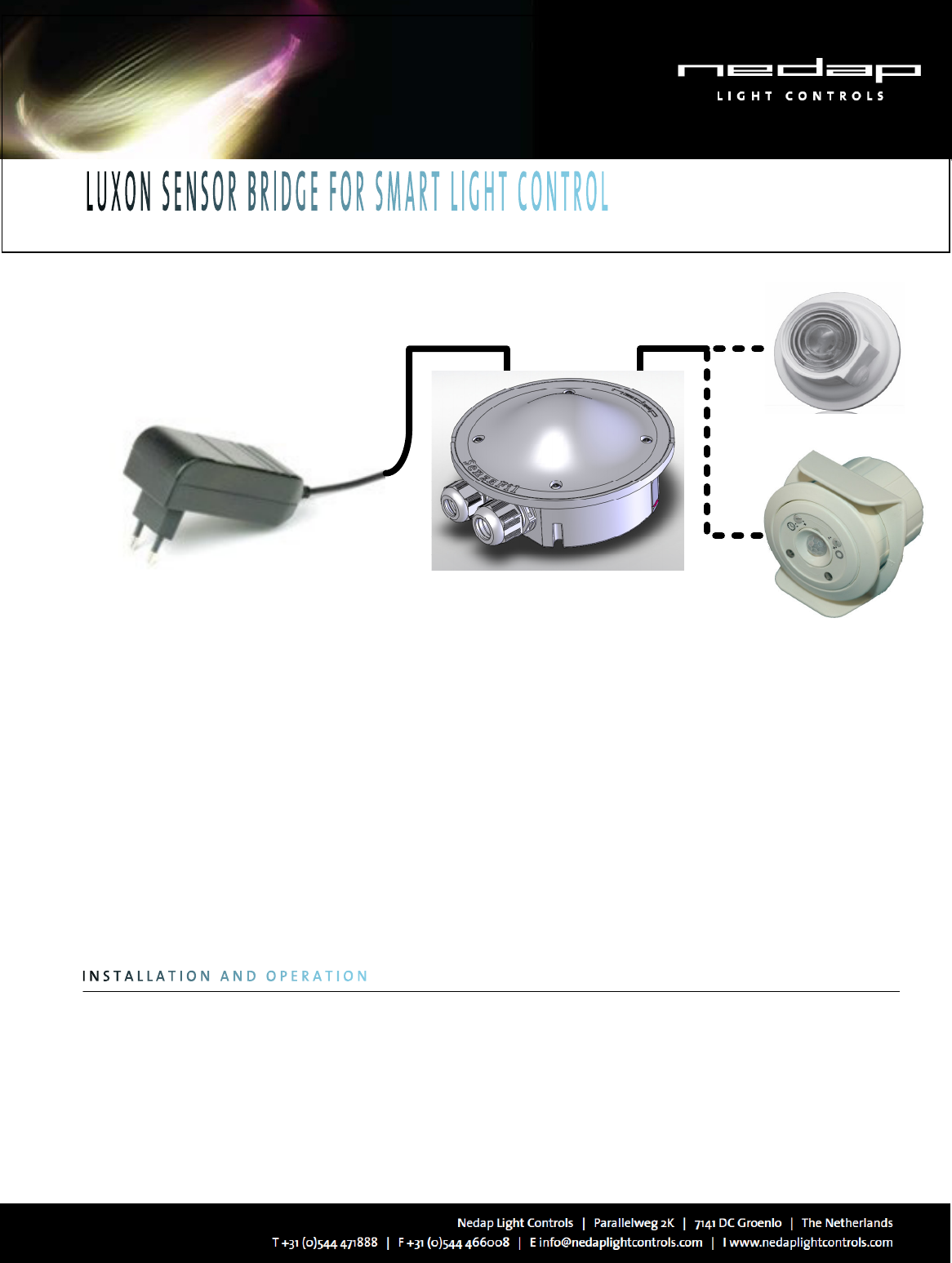
Powering:
The Sensor Bridge is powered from a mains adapter or similar DC-source supplying 12 to 24V. This voltage is also available
for the sensor, so you can choose the supply voltage depending on the voltage needed for the sensor to be used.
Power connection via either a standard DC-plug or screw terminals.
Option for Nedap Luxon wireless light control system
LIGHT SENSOR
MOVEMENT SENSOR
MAINS ADAPTER
NEDAP RF SENSOR BRIDGE
Figure 2: Wiring overview for the Luxon Sensor Bridge
Compatible sensors:
Many sensor types can be used:
- Switches;
- 1 to 10V dimmers (resistive and electronic potentiometers);
- Light sensors;
- Sensors for detection of movement and / or room occupancy.
To select an appropriate sensor that fits your application and your preferences, please use the listing available on our web
site www.nedaplightcontrols.com.
The Sensor Bridge may only be installed and configured by qualified and trained personnel.
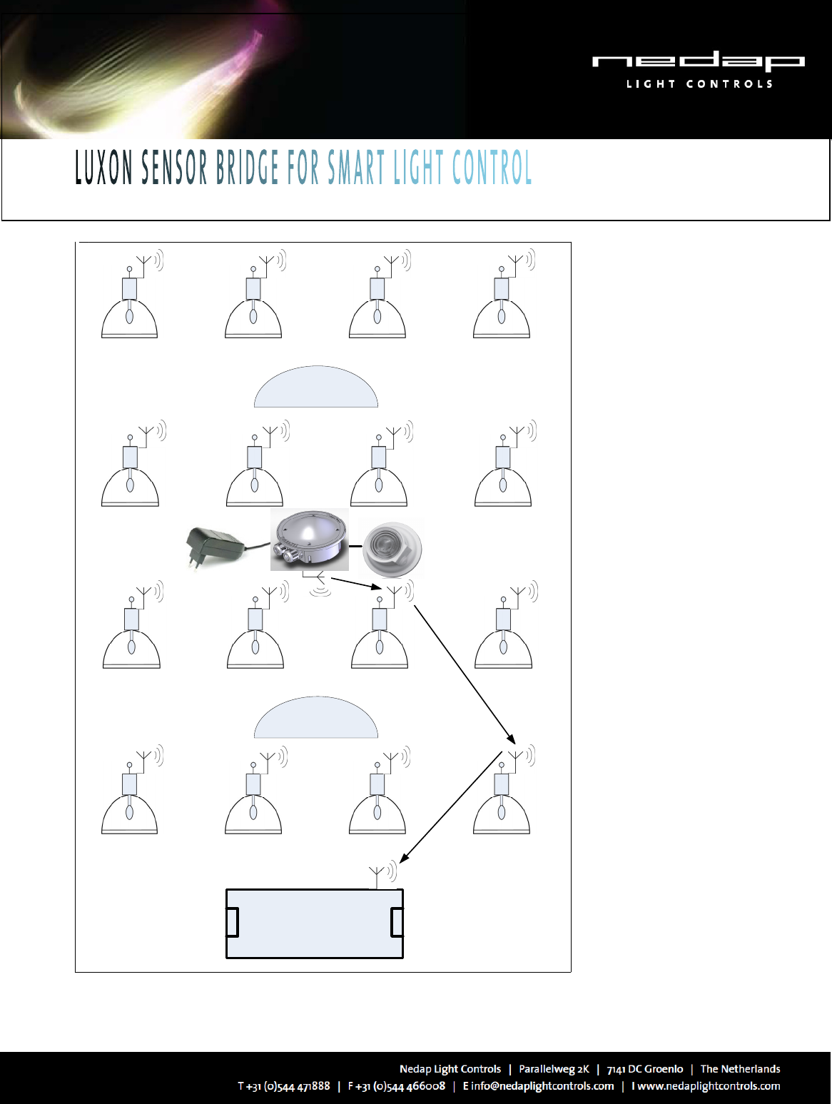
For an installation example please see figure 3 below.
The Sensor Bridge can be ordered for surface mounting or for recessed mounting; the dome should always point
downwards if mounted at approximately the same height as the Senzafil lamp drivers. For recessed mounting, both
clamps can be used to secure the unit to a ceiling element. After finishing the connections, the dome shall be secured to
the base using four torx screws. After powering the Sensor Bridge it shall be configured using the Senzafil Configuration
Tool. From the pick list you can easily select the used sensor with its characteristics.
Option for Nedap Luxon wireless light control system
SKYLIGHT
SKYLIGHT
NEDAP LUXON LIGHT
CONTROLLER
SENSOR
DATA FLOW
IN SENZAFIL
RF MESH
NETWORK
NEDAP LUXON SENSOR
BRIDGE WITH LIGHT
SENSOR
HID LAMPS WITH
NEDAP LAMP
BALLAST
Figure 3: Installation example for the Sensor Bridge with HID lamps controlled via the
Wireless Senzafil Mesh Network in a building with skylights.
Option for Nedap Luxon wireless light control system
Luxon Sensor Bridge for surface mounting: 8018669, ordering nr. 9949348
Luxon Sensor Bridge for recessed mounting: 8019037, ordering nr. 9949356
Description
DescriptionDescription
Description
Details
DetailsDetails
Details
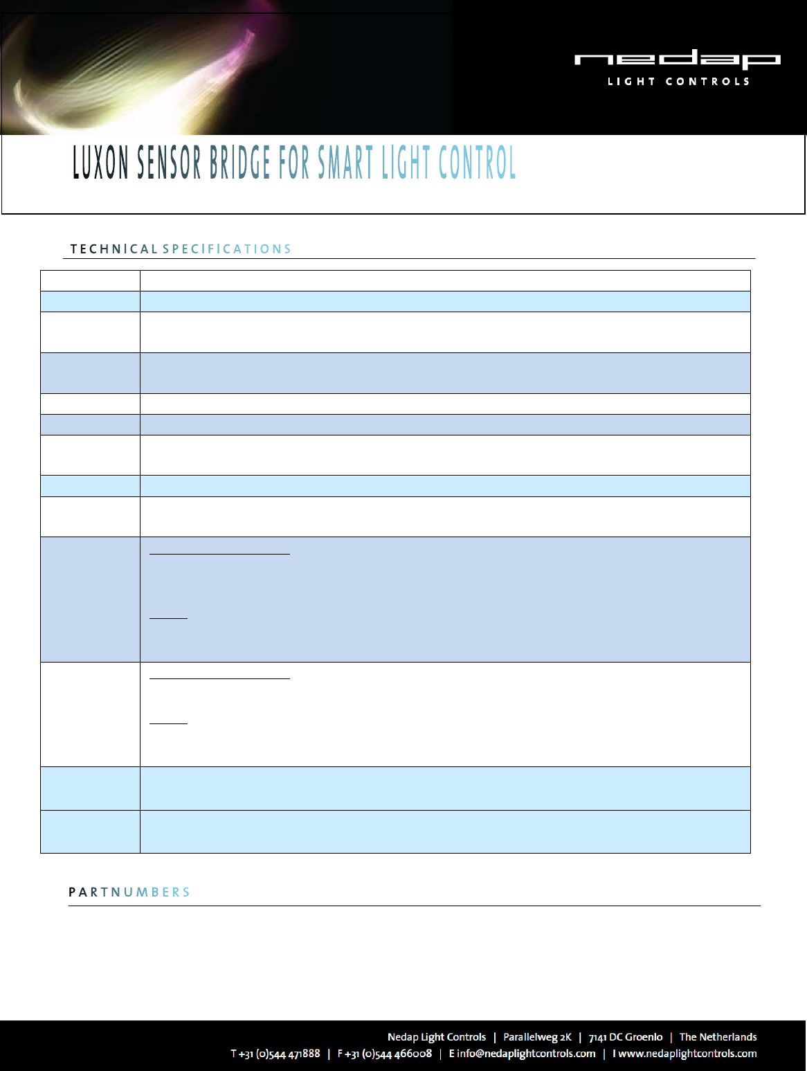
Supply Voltage
10 to 28VDC
Supply current
Sensor Bridge: max 100mA, standby < 20mA
External sensor: max 200mA
Mains adapter
specification
12V / 4W or
24V / 6W
Dimensions Diameter: 130 mm, Height 70 mm
Weight
0.23kg including cable glands
Enclosure
protection IP67 (the en
IP67 (the enIP67 (the en
IP67 (the enclosed cable glands must be used properly)
closed cable glands must be used properly)closed cable glands must be used properly)
closed cable glands must be used properly)
Housing colors Base: light gray, top: milky grey-white
Connector power: standard DC jack with 2.0 mm centre pin or 2 screw terminals 30-18 AWG, or 0.25 to 1.5 sq.mm.
sensor: 3 screw terminals 30-18 AWG, or 0.25 to 1.5 sq.mm.
Safety
United States and Canada
United States and Canada United States and Canada
United States and Canada
An UL listed
An UL listed An UL listed
An UL listed mains adapter
mains adapter mains adapter
mains adapter shall
shallshall
shall
be used
be usedbe used
be used
that meets the NEC Class 2 requirements
that meets the NEC Class 2 requirementsthat meets the NEC Class 2 requirements
that meets the NEC Class 2 requirements
The Sensor bridge is designed to meet UL6
The Sensor bridge is designed to meet UL6The Sensor bridge is designed to meet UL6
The Sensor bridge is designed to meet UL619
1919
19
Europe
EuropeEurope
Europe
An
AnAn
An
EN60950 compliant mains adapter must be used
EN60950 compliant mains adapter must be usedEN60950 compliant mains adapter must be used
EN60950 compliant mains adapter must be used
EMC
United States a
United States aUnited States a
United States and Canada
nd Canada nd Canada
nd Canada
FCC47 part
FCC47 part FCC47 part
FCC47 part 15
15 15
15
Europe
EuropeEurope
Europe
EN
ENEN
EN301
301301
301
489
489489
489-
--
-1 and 489
1 and 4891 and 489
1 and 489-
--
-3
33
3
EN300 328
EN300 328EN300 328
EN300 328
Temperature Operating 0
Operating 0 Operating 0
Operating 0 –
––
–
60°C, Storage
60°C, Storage 60°C, Storage
60°C, Storage -
--
-20 to 80°C
20 to 80°C20 to 80°C
20 to 80°C
Humidity 25 to 95 % RH. Condensing and icing max 5% of time
25 to 95 % RH. Condensing and icing max 5% of time25 to 95 % RH. Condensing and icing max 5% of time
25 to 95 % RH. Condensing and icing max 5% of time
Option for Nedap Luxon wireless light control system
F
FF
FCC Declarations
CC DeclarationsCC Declarations
CC Declarations
Compliance statement (part 15.19)
Compliance statement (part 15.19) Compliance statement (part 15.19)
Compliance statement (part 15.19)
This device complies with part 15 of the FCC Rules and to RSS210 of Industry Canada.
Operation is subject to the following two conditions:
(1) this device may not cause harmful interference, and
(2) this device must accept any interference received, including interference that may cause undesired operation.
Déclaration Conformit
Déclaration ConformitDéclaration Conformit
Déclaration Conformité
éé
é
Cet appareil se conforme aux normes RSS exemptés de license du Industry Canada.
L'opération est soumis aux deux conditions suivantes
(1) cet appareil ne doit causer aucune interférence, et
(2) cet appareil doit accepter n'importe quelle interférence, y inclus interférence qui peut causer une opération non pas voulu de cet appareil.
Warning (part 15.21)
Warning (part 15.21)Warning (part 15.21)
Warning (part 15.21)
Changes or modifications not expressly approved by the party responsible for compliance could void the user’s authority to operate the
equipment.
RF E
RF ERF E
RF Exposure (OET Bulletin 65)
xposure (OET Bulletin 65)xposure (OET Bulletin 65)
xposure (OET Bulletin 65)
To comply with FCC RF exposure requirements for mobile transmitting devices, this transmitter should only be used or installed at locations where
there is at least 20cm separation distance between the antenna and all persons.
Version: 0.4
Date: 20110223