Nedap N V T325RRFMDID ASSY T325R RF+MD+RFID User Manual Manual
N. V. Nederlandsche Apparatenfabriek NEDAP ASSY T325R RF+MD+RFID Manual
UserManual.wiki
>
Nedap N V
>
T325RRFMDID User Manual
>
Manual
Contents
1.
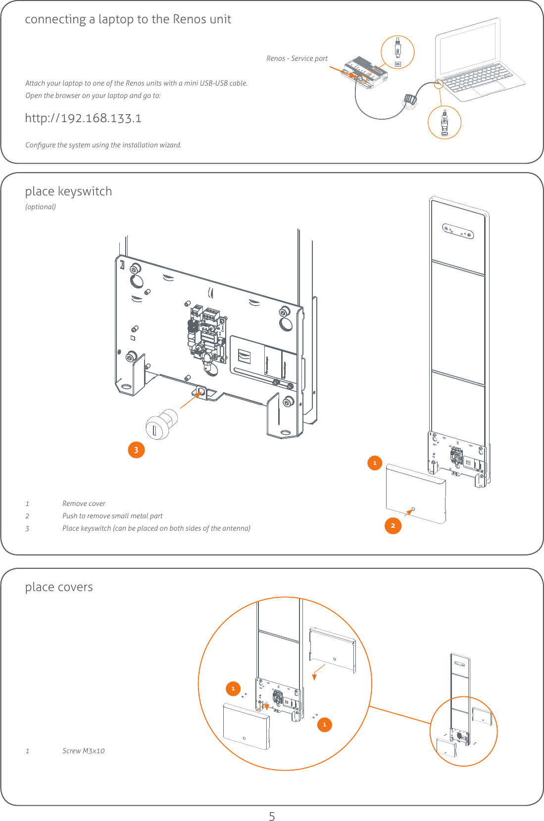
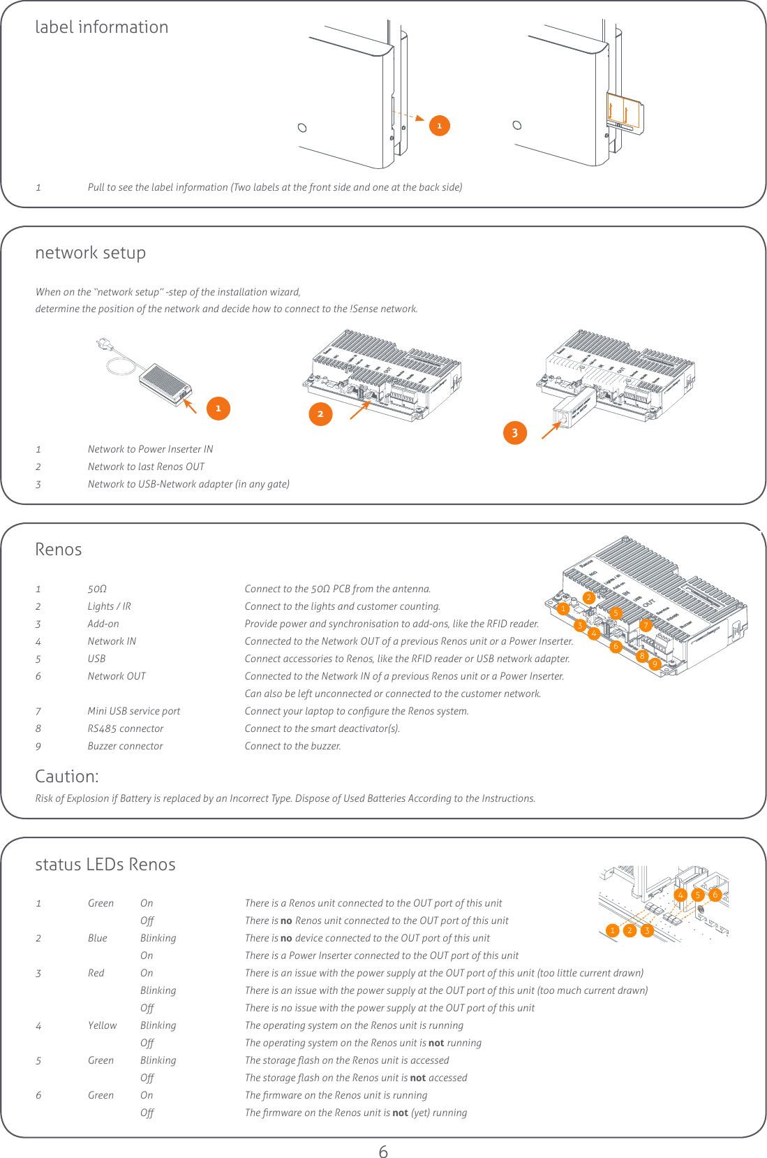
Manual
2.
Manual UHF portion
Manual
Navigation menu
Upload a User Manual
Namespaces
Wiki Guide
HTML
PDF
Info
Views
User Manual
Discussion / Help
Navigation