Nedap N V TDC Deactivator User Manual TDC Duc Buzzer Buzduc V1 60
N. V. Nederlandsche Apparatenfabriek NEDAP Deactivator TDC Duc Buzzer Buzduc V1 60
Contents
- 1. user manual
- 2. User Manual 1
- 3. User Manual 2
User Manual 1

Date: 08 September 2004 Version 1.60
This information is furnished for guidance, and with no guarantee as to its accuracy or completeness; its publication conveys no license under any patent or other right, nor does
the publisher assume liability for any consequence of its use; specifications and availability of goods mentioned in it are subject to change without notice; it is not to be
reproduced in any way, in whole or in part, without the written consent of the publisher.
_________________________________________________________________________________________________________
© Nedap Retail Support P.O. Box 102 NL-7140 AC Groenlo the Netherlands
Installation Sheet
- TDC DUC
- TDC BUZDUC
- TDC BUZZER
- TWO- / FOUR WAY SPLITTER

2
TDC Duc – Buzzer - BuzDuc V1.60 | Nedap Retail Support
© 2004 Nedap Retail Support -
Netherlands
Parallelweg 2d, 7141 DC Groenlo
The software / hardware described in this book / file is furnished under a license agreement and may be used only in accordance with the terms of
the agreement.
Documentation version 1.60
Copyright Notice
All Rights Reserved.
Any technical documentation that is made available by Nedap Retail Support is the copyrighted work of Nedap Retail Support and is owned by Nedap
Retail Support.
NO WARRANTY. The technical documentation is being delivered to you and Nedap Retail Support makes no warranty as to its accuracy or use. Any
use of the technical documentation or the information contained therein is at the risk of the user.
Documentation may include technical or other inaccuracies or typographical errors.
Nedap Retail Support reserves the right to make changes without prior notice.
No part of this publication may be copied without the express written permission of Nedap Retail Support, Parallelweg 2d, 7141 DC Groenlo,
Netherlands.
Trademarks
Nedap, the Nedap logo, Nedap EASi/Net and the Nedap EASi/Net are registered trademarks of Nedap N.V. Groenlo.
Other product names mentioned in this manual may be trademarks or registered trademarks of their respective companies and are hereby
acknowledged.
Printed in the Netherlands

3
TDC Duc – Buzzer - BuzDuc V1.60 | Nedap Retail Support
- support-rs@nedap.com
- H. Hammer
+31 (0) 544-47 15 19
hans.hammer@nedap.com
- H. Broekhuis
+31 (0) 544-47 15 02
han.broekhuis@nedap.com
Visitor’s address:
Nedap Retail Support
Parallelweg 2d
Groenlo
Netherlands
Postal address:
Nedap Retail Support
Postbus 102
7140 AC Groenlo
Fax
+31 (0) 544-46 58 14
Technical Support:

4
TDC Duc – Buzzer - BuzDuc V1.60 | Nedap Retail Support
Technical Support: 3
Visitor’s address: 3
Postal address: 3
Fax 3
Table of content 4
TDC/SDC accessories 5
TDC DUC 6
Adjusting the dip switch SW1 6
Scope settings 7
Connector K3 7
TDC Buzzer 8
Adjusting the buzzer volume 8
TDC Buzduc 9
Connector K3 9
Release versions 9
Two- and four way splitters 10
EASiTM/Net 10
Filters 11
TDC Unit - 2 way splitter / 4 way splitter 11
2 way splitter / 4 way splitter - Antenna 11
2 way splitter / 4 way splitter - DUC 11
2 way splitter / 4 way splitter 11
DUC - Add On antenna 11
Maximum cable length 11
Examples Version 1 12
Examples Version 2 13
Table of content

5
TDC Duc – Buzzer - BuzDuc V1.60 | Nedap Retail Support
For the TDC / SDC are the following accessories available:
• TDC DUC
• TDC Buzzer
• TDC BuzDuc
• Two-way Splitter
• Four-way Splitter
TDC/SDC accessories
6
TDC Duc – Buzzer - BuzDuc V1.60 | Nedap Retail Support
This is a 50 ohms to O-shape (scanner) antenna coupling-unit.
3K
1WS
1K 3X
4X
5X
Ground
The DUC is used to connect an O-shape antenna to a deactivator.
It contains a four-fold dipswitch to switch four tuning capacitors.
In this way it is possible to optimally adapt in 16 steps.
With the present capacitors O-shapes of 450 uH up to 3500uH can be accomodated.
This range is sufficient to accomodate the normal O-shape- and scanner antennas.
With jumper X3 it is possible to connect the system ground to the ground of the housing
if necessary.
It is not recommended to do this to avoid ground loops.
As a default factory setting, this jumper is not placed.
Jumper Default setting Application
X3 off Ground to housing (jumper is present on PCB)
X4 off X4 Off, X5 On, attenuation 3Db
X5 on X4 On, X5 Off, attenuation 0Db
Adjusting the dip switch SW1
Mount the preferred antenna loop and connect it to the DUC.
• The DUC must be as close as possible to the loop (maximum distance is 30cm)
• The wires to the DUC must be twisted
Connect the DUC to the TDC.
Turn on the TDC and choose for the antenna to be adjusted, in the hand terminal mux
menu. Connect the scope to connector K9 and put jumper K8 to position 2-3.
TDC DUC
7
TDC Duc – Buzzer - BuzDuc V1.60 | Nedap Retail Support
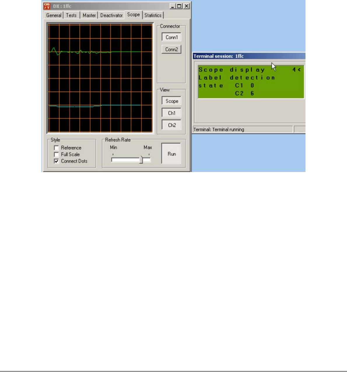
Scope settings
0,5V/div, 200uS/div. Take the channel with the directional coupler test cable. Put the
four dipswitches in the “Off” position. A directional coupler signal with a maximum of 3Vtt
is visible. Choose a combination of switch settings at which the directional coupler is as
small as possible. ( > 500mVtt). This will be the most optimal setting.
OST/Builder
At the terminal screen (7-7-2) use the options 3 or 4 to view the directional coupler
signal.
Attenuate the DUC by using the dipswitch on the (Buz-)DUC PCB and the OS/T Builder.
Try to get the blue line as horizontal as possible
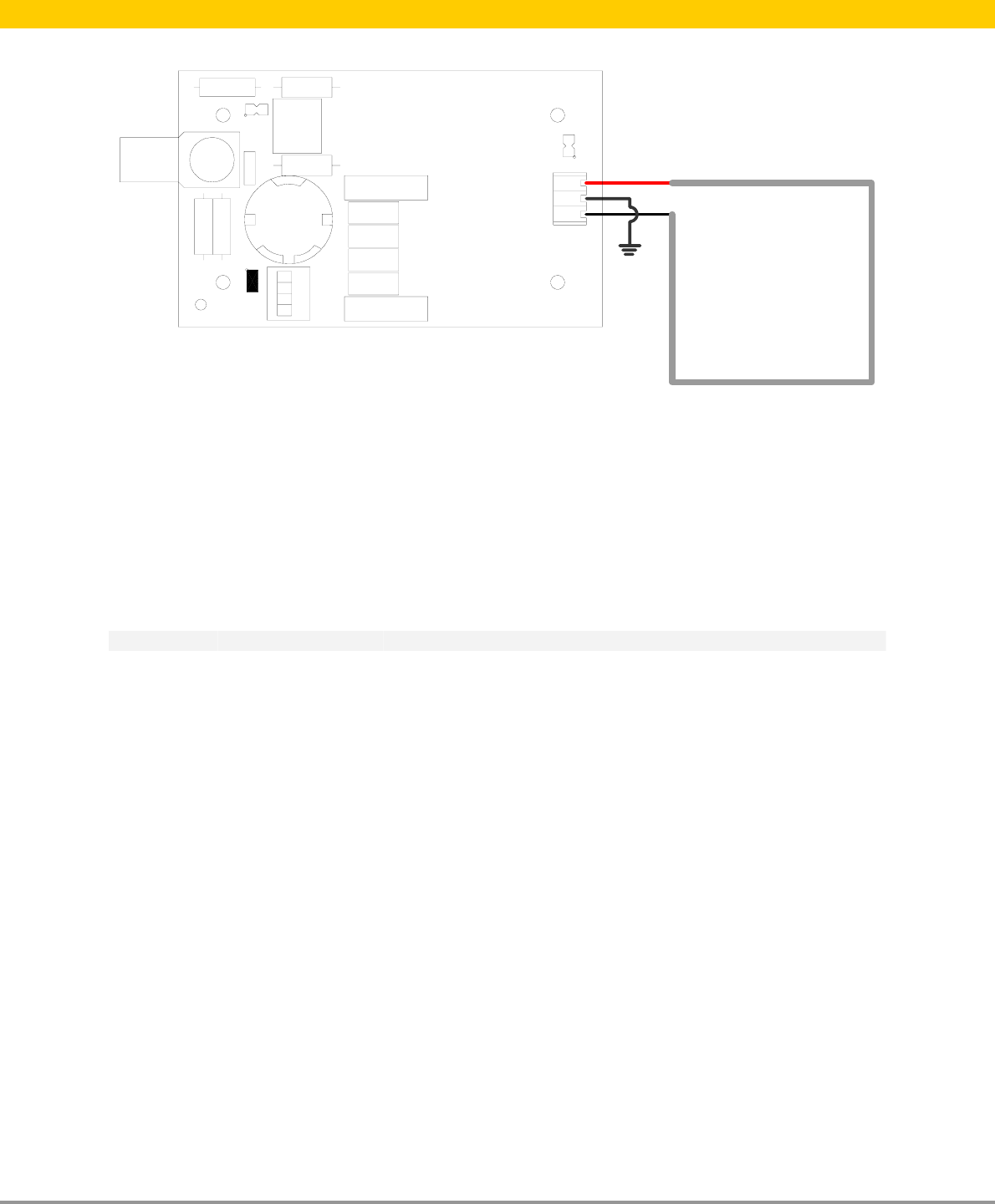
Connector K3
The add-on antenna will be connected to connector K3.
Version 1: two pole connector
The wires of the loop antenna will be connected to the two poles of the connector.
Version 2: three pole connector (April 2004)
The shielding of the cable will be connected to the middle pole, the other two wires to the
other two poles of the connector.
8
TDC Duc – Buzzer - BuzDuc V1.60 | Nedap Retail Support
K1
K2
P1
X3
The TDC contains two independent deactivator channels. When both channels are used, it
is desired to have a sound at the antenna. The TDC buzzer is used to create sound when
an event occurs. It will be placed in the coax cable going to the antenna and will be
activated by the TDC. The buzzer volume is adjustable with pot-meter P1.
With jumper X3 the system ground can be connected with the ground of the housing. It
is recommended not to do this to avoid ground loops. By factory default this jumper is
not placed.
Adjusting the buzzer volume
Mount the TD Buzzer and connect the antenna to the TDC. In the hand held terminal
buzzer test menu the buzzer can be tested. Adjust P1 to the desired volume.
TDC Buzzer
9
TDC Duc – Buzzer - BuzDuc V1.60 | Nedap Retail Support
SW1
K1
K3
X3
X4
X5
P1
The TDC Buzduc is a combination of the TDC Duc and TDC Buzzer. With the TDC Buzduc
a hand- or flatbed scanner antenna with a local buzzer can be realized. The DUC is meant
to connect an O-shape antenna to a deactivator.
It contains a four-fold dipswitch to switch four tuning capacitors.
In this way it is possible to optimally adapt in 16 steps.
With the present capacitors O-shapes of 450uH up to 3500uH can be adapt.
This range is sufficient to adapt the normal O-shape- and scanner antennas.
The buzzer volume is adjustable with pot-meter P1.
With jumper X3 the system ground can be connected with the ground of the housing. It
is recommended not to do this to avoid ground loops. By factory default this jumper is
not placed.
Jumper Default setting Application
X3 off Ground to housing (jumper is present on PCB)
X4 off X4 Off, X5 On, attenuation 3Db
X5 on X4 On, X5 Off, attenuation 0Db
Dip switch adjustments: Same as TDC DUC
Buzzer volume adjustments: Same as TDC Buzzer
Connector K3
The add-on antenna will be connected to connector K3.
Release versions
Version 1: two pole connector K3
The wires of the loop antenna will be connected to the two poles of the connector.
Version 2: three pole connector K3 (>April 2004)
The shielding of the cable will be connected to the middle pole, the other two wires to the
other two poles of the connector.
TDC Buzduc
10
TDC Duc – Buzzer - BuzDuc V1.60 | Nedap Retail Support
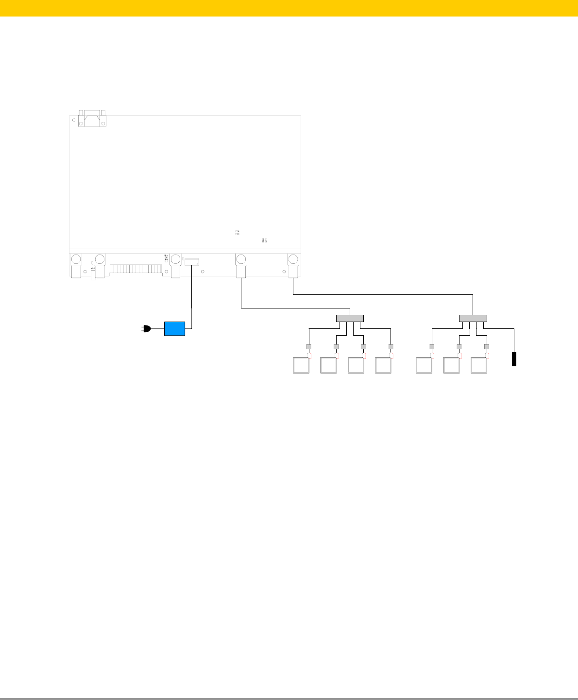
The two- and four way splitters are used to expand the coaxial cable from a channel of
the TDC to for two or four deactivator antennas.
EASiTM/Net
It is not possible to watch the data of one specific antenna in EASiTM/Net. The counting
will be done over the entire group of antenna’s which are connected through the splitter
to one channel of the TDC.
Powersplitter 4x Powersplitter 4x
TDC Standalone
Dummyload
Example:TDC with 2 four way splitters, 7 add-on antenna’s and 7 TDC Ducs or 7 TDC
Buzducs and a dummyload for the last channel
Two- and four way splitters

11
TDC Duc – Buzzer - BuzDuc V1.60 | Nedap Retail Support
TDC Unit - 2 way splitter / 4 way splitter (Belden 9907)
One filter at the TDC, one filter at the splitter and every 9 meters one filter.
2 way splitter / 4 way splitter - Antenna (Belden 9907)
Every 9 meters one filter.
2 way splitter / 4 way splitter - DUC (Belden 9907)
A filter at the DUC and every 9 meters one filter.
2 way splitter / 4 way splitter
Use a 50 Ohm dummy load on every unused output of the splitter is not in use.
DUC - Add On antenna
No filter, distance not longer then 30 centimeter.
Maximum cable length
The maximum cable length from the output of the TDC to the antenna is 15 meters. A
splitter must be placed as close as possible to the antennas.
Filters
12
TDC Duc – Buzzer - BuzDuc V1.60 | Nedap Retail Support
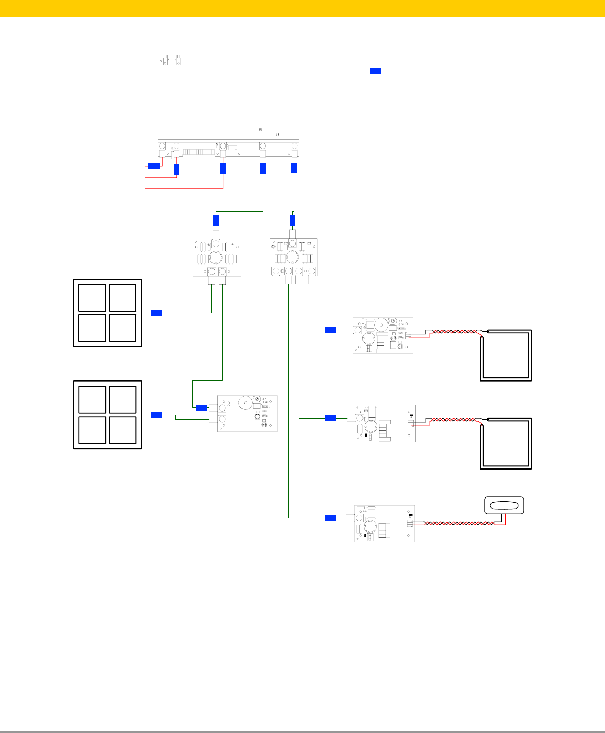
Examples how to connect deactivator antennas to the TDC. Version 1 Duc’s and BuzDuc’s
are used.
CDT
Two way Splitter Four way Splitter
TDC BuzDuc (Version 1)
TDC Duc (Version 1)
TDC Buzzer
TDC Duc (Version 1)
Dummy Load
Loop antenna
Add on antenna
Loop antenna
Deactivator antenna
Deactivator antenna
Master / slave
Sync
Sync
= Filter
Examples Version 1
13
TDC Duc – Buzzer - BuzDuc V1.60 | Nedap Retail Support
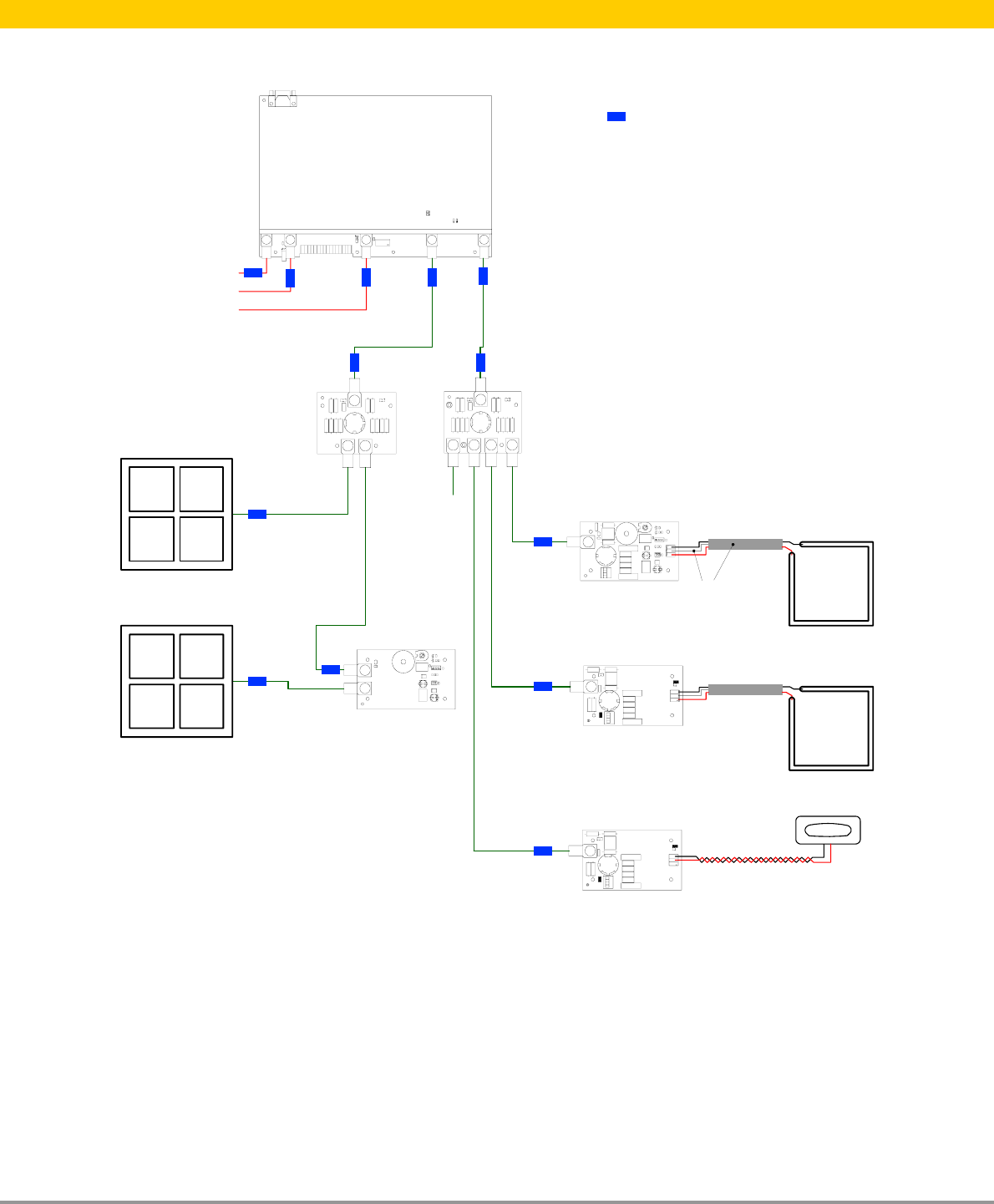
Examples how to connect deactivator antennas to the TDC. Version 2 Duc’s and BuzDuc’s
are used.
CDT
Two way Splitter Four way Splitter
TDC BuzDuc (Version 2)
TDC Duc (Version 2)
TDC Buzzer
TDC Duc (Version 2)
Dummy Load
Loop antenna
Add on antenna
Loop antenna
Deactivator antenna
Deactivator antenna
Master / slave
Sync
Sync
= Filter
Shielding
Examples Version 2