Nedap N V UPASSACC UHF RFID reader User Manual uPASS Access
N. V. Nederlandsche Apparatenfabriek NEDAP UHF RFID reader uPASS Access
UserManual.wiki
>
Nedap N V
>
UPASSACC User Manual
13_uPassAccess_InstallGuide_E CGDUPASSACC
Navigation menu
Upload a User Manual
Namespaces
Wiki Guide
HTML
PDF
Info
Views
User Manual
Discussion / Help
Navigation
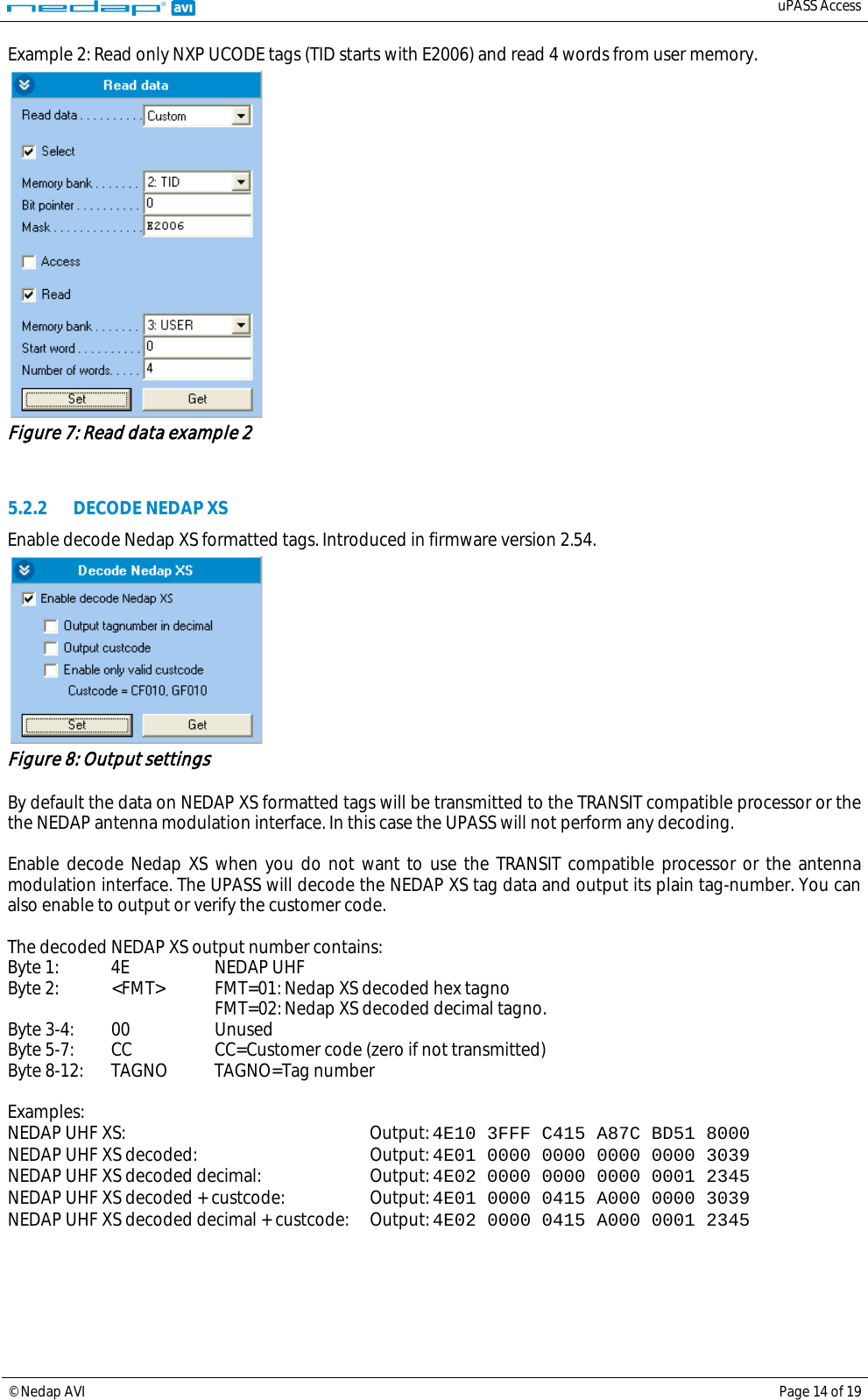
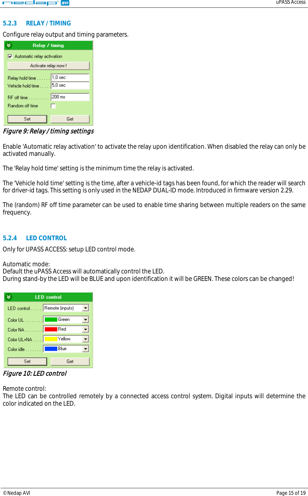
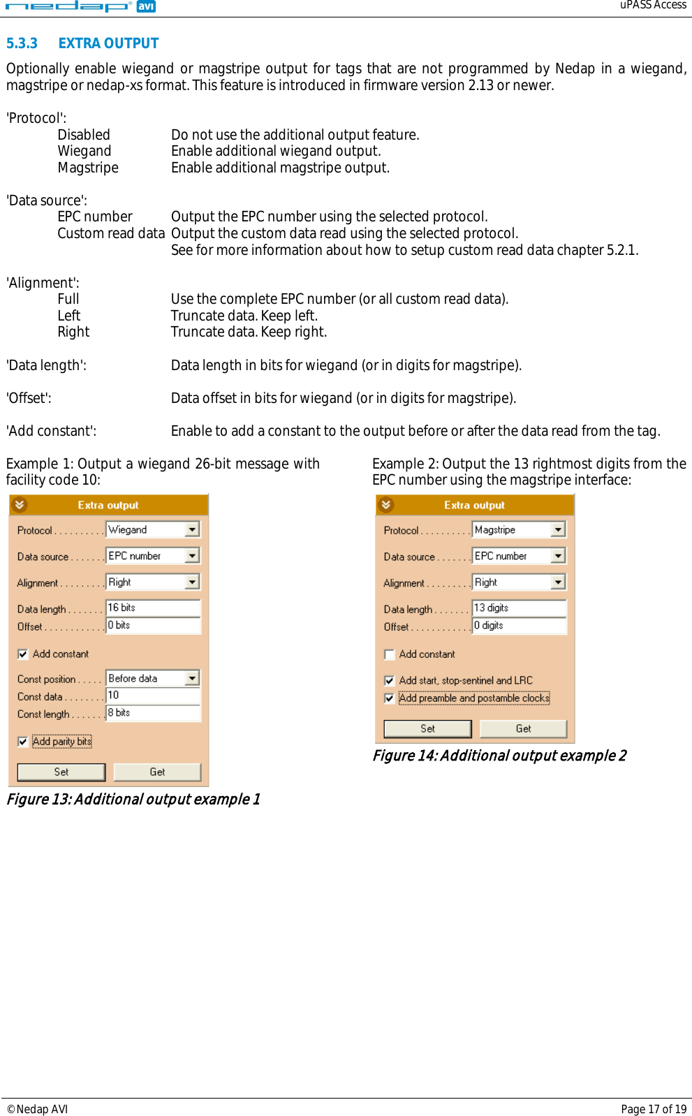
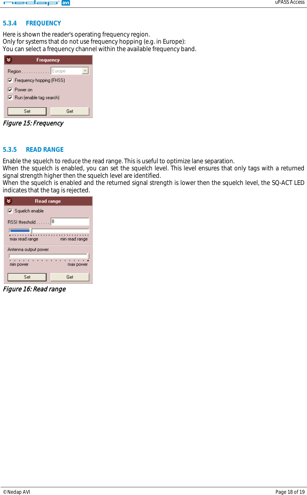
![uPASS Access © Nedap AVI Page 16 of 19 5.3 EXPERT SETTINGS Click 'Options', 'Usermode', 'Expert' to show additional configuration settings for advanced users. 5.3.1 OUTPUT Configure communication output settings. Figure 11: Output settings Select 'Enable serial id-events' to enable the serial output upon identification. Only disable the serial id-events to optimize the identification speed when using the wiegand or magstripe interface or the TRANSIT compatible processor. When 'Fast repeat serial id-events' is selected (default) the serial output is repeated upon every identification. When this option is disabled, the message is only sent once. Enable 'Repeat using hold-time interval' to repeat id-events with hold-time interval. The repeating will be enabled for the serial and also for the wiegand or magstripe interface. 'Enable vehicle id-events' allows enabling or disabling the id-event messages for vehicle-ids. This may be useful in combination with the NEDAP DUAL-ID mode and an access control panel that does not support the dual-id feature. 5.3.2 OUTPUT MESSAGE FORMAT Configure output message format. Figure 12: Output message format The output message format is configurable: <prefix> [<tagstatus>] [<epclen>] [<epc>] [<datlen>] [<data>] <suffix> [ CR/LF ] Note: When the output message format is changed, identified tags may no longer be shown in the UHFTOOL.](https://usermanual.wiki/Nedap-N-V/UPASSACC/User-Guide-1931395-Page-16.png)