Nedap N V UPASSACC UHF RFID reader User Manual uPASS Access
N. V. Nederlandsche Apparatenfabriek NEDAP UHF RFID reader uPASS Access
13_uPassAccess_InstallGuide_E CGDUPASSACC
2013-03-18 Doc.no. 5281326
This information is furnished for guidance, and with no guarantee as to its accuracy or completeness; its publication conveys
no license under any patent or other right, nor does the publisher assume liability for any consequence of its use; specifica-
tions and availability of goods mentioned in it are subject to change without notice; it is not to be reproduced in any way, in
whole or in part, without the written consent of the publisher.
© Nedap AVI Page 1 of 19
uPASS Access
Installation Guide

uPASS Access
© Nedap AVI Page 2 of 19
FCC ID: CGDUPASSACC
IC: 1444A-UPASSACC
Compliace statement:
This device complies with part 15 of the FCC rules and to RSS210 of Industrial Canada.
Operation is subject to the following two conditions:
(1) this device may not cause harmful interference, and
(2) this device must accept any interference received, including interference that may cause undesired operation.
Déclaration conformitè:
Cet appareil se conforme aux normes RSS210 exemptés de license du Industry Canada.
L'opération est soumis aux deux conditions suivantes:
(1) cet appareil ne doit causer aucune interférence, et
(2) cet appareil doit accepter n'importe quelle interférence, y inclus interférence qui peut causer une opération
non pas voulu de cet appareil.
Warning:
Changes or modifications not expressly approved by the party responsible for compliance could void the user's
authority to operate the equipment.
This equipment complies with FCC RF radiation exposure limits set forth for an uncontrolled environment.
This device shall be installed to provide a separation distance of at least 20 cm from all persons.

uPASS Access
© Nedap AVI Page 3 of 19
CONTENTS
1 INTRODUCTION ....................................................................................................................................................................................... 4
1.1 SUPPORTED TAGS ........................................................................................................................................................................ 4
1.2 TAG SECURITY ............................................................................................................................................................................... 5
2 INSTALLATION ......................................................................................................................................................................................... 6
2.1 SAFETY INSTRUCTION ................................................................................................................................................................ 6
2.2 MOUNTING INSTRUCTIONS ...................................................................................................................................................... 6
3 CONNECTIONS ......................................................................................................................................................................................... 8
3.1 POWER SUPPLY ............................................................................................................................................................................. 9
3.2 COMMUNICATION ....................................................................................................................................................................... 9
3.2.1 RS485 .................................................................................................................................................................................. 9
3.2.2 USB ....................................................................................................................................................................................... 9
3.2.3 WIEGAND / MAGSTRIPE ............................................................................................................................................ 10
3.3 LED CONTROL ............................................................................................................................................................................. 11
3.4 TAMPER SWITCH ........................................................................................................................................................................ 11
3.5 NEDAP ANTENNA INTERFACE .............................................................................................................................................. 11
4 UHF FREQUENCIES .............................................................................................................................................................................. 12
4.1 RADIO REGULATIONS .............................................................................................................................................................. 12
4.2 FREQUENCY CHANNEL SELECTION .................................................................................................................................... 12
5 READER CONFIGURATION ................................................................................................................................................................ 13
5.1 UHFTOOL SOFTWARE .............................................................................................................................................................. 13
5.2 SETTINGS ...................................................................................................................................................................................... 13
5.2.1 READ DATA .................................................................................................................................................................... 13
5.2.2 DECODE NEDAP XS ..................................................................................................................................................... 14
5.2.3 RELAY / TIMING ............................................................................................................................................................ 15
5.2.4 LED CONTROL ............................................................................................................................................................... 15
5.3 EXPERT SETTINGS ...................................................................................................................................................................... 16
5.3.1 OUTPUT ........................................................................................................................................................................... 16
5.3.2 OUTPUT MESSAGE FORMAT ................................................................................................................................... 16
5.3.3 EXTRA OUTPUT ............................................................................................................................................................ 17
5.3.4 FREQUENCY ................................................................................................................................................................... 18
5.3.5 READ RANGE ................................................................................................................................................................. 18
A TECHNICAL SPECIFICATIONS .......................................................................................................................................................... 19
B PART NUMBERS .................................................................................................................................................................................... 19

uPASS Access
© Nedap AVI Page 4 of 19
1 INTRODUCTION
The uPASS Access reader offers a revolutionary and enduring solution for hands-free door access. The uPASS
Access has the dimensions of a conventionally access control reader but offers read range unmatched in the
industry. The uPASS Access offers identification up to 2 meter (6 feet) using the latest UHF technology.
The uPASS Access includes a RS485 interface, a wiegand/magstripe and a RF-modulation interface.
The uPASS Access can also be connected to NEDAP AEOS access control hardware such as the AP1001, using the
RF-modulation interface.
The uPASS Access does not offer the TRANSIT compatibility features.
The uPASS Access is equipped with a fixed shielded cable pigtail, 12 x 0.14 mm2
In the case of extending this pigtail cable, ONLY shielded cables shall be used and all shields shall be connected
to the metal case of the external device(s).
, length 5 meter (15 feet). The
cable shield shall be connected to the metal case of the external device or external devices.
1.1 SUPPORTED TAGS
Any EPC Class 1 Gen 2 tag is supported by the uPASS Access.
NEDAP formatted UHF tags can have the following formats:
• NEDAP UHF wiegand tags
These tags will contain all wiegand information including facility code and parity bits. All wiegand formats
can be supported. The reader transparently sends this information via the wiegand outputs. There is no
need to change any DIP-switches or configuration settings. See chapter 3.2.3 for wiring details.
Note: The Wiegand output format is determined by the tag and not by the reader.
• NEDAP UHF magstripe tags
These tags will contain all magstripe information. The reader transparently sends this information onto the
magstripe interface. There is no need to change any DIP-switches or configuration settings. See chapter
3.2.3 for wiring details.
Note: The magstripe output format is determined by the tag and not by the reader.
• NEDAP UHF XS tag
These tags are especially programmed in the same format as our 2.45GHz AVI tags (Compact-Tag, Window-
Button and Heavy-Duty-Tag). The tags will also have a customer-code and id-number. The reader will
modulate the tag-info onto the Nedap antenna interface output, which can be connected to NEDAP AEOS
access control hardware such as the AP1001.
Note: See also the 'decode nedap xs' feature as described in chapter 5.2.2.

uPASS Access
© Nedap AVI Page 5 of 19
1.2 TAG SECURITY
EPC (Electronic Product Code) tags were introduced as a possible successor to the barcode with added
functionalities. The tag emits its EPC in plain text. This makes the tags vulnerable to cloning and counterfeiting
attacks. Unlike many 13MHz smartcards, EPC tags do not support any DES, 3DES or AES encryption.
EPC tags contain a data field known as the Tag Identifier (TID). At the discretion of the EPC manufacturer, the
value may be factory programmed and locked, ensuring that tags have a unique identity and (theoretically)
cannot be cross-copied. This TID based anti-cloning mechanism is not considered to be a strong protection.
NEDAP UHF tags support a locked serialized TID and the uPASS Access reader can be configured to read the TID
data field.
In addition NEDAP has also implemented an advanced anti-cloning and anti-counterfeiting method based upon
a two way authentication. This feature is supported in combination with all NEDAP UHF tags.
By default the uPASS Access reader is configured to read any EPC tag.
We encourage customers to enable the TID-check or the two way authentication. But also advise not to
completely rely on these methods in high-security applications.
uPASS Access
© Nedap AVI Page 6 of 19
2 INSTALLATION
2.1 SAFETY INSTRUCTION
The following safety precautions should be observed during normal use, service and repair.
• The uPASS Access may only be installed and serviced by qualified service personnel.
• Disconnect the power supply before (dis)connecting any wires, uPASS Access is NOT hot-swappable, so
when making or changing connections, power must be switched OFF.
• The cable shield shall be connected with safety ground and the metal case of the external device(s).
• To be sure of safety, do not modify or add anything to the uPASS Access other than mentioned in this
installation guide or indicated by NEDAP N.V.
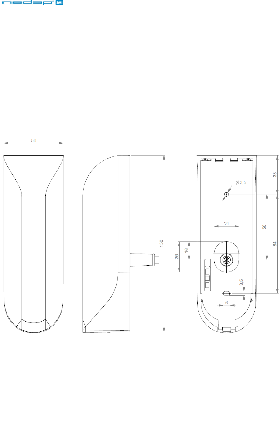
2.2 MOUNTING INSTRUCTIONS
The uPASS Access can be mounted to any surface, including directly to metal. See the picture below for details
about the dimensions.
Figure 1: uPASS Access dimensions (mm)
Mount the base-plate on the required location.
Ensure that it is placed correctly covering the cable entry hole. Properly fix the base-plate into its position using
the 2 screws. When mounting on a stone or concrete wall drill 5mm holes for the plugs. When mounting on
wood, drill with 2.5mm.
uPASS Access
© Nedap AVI Page 7 of 19
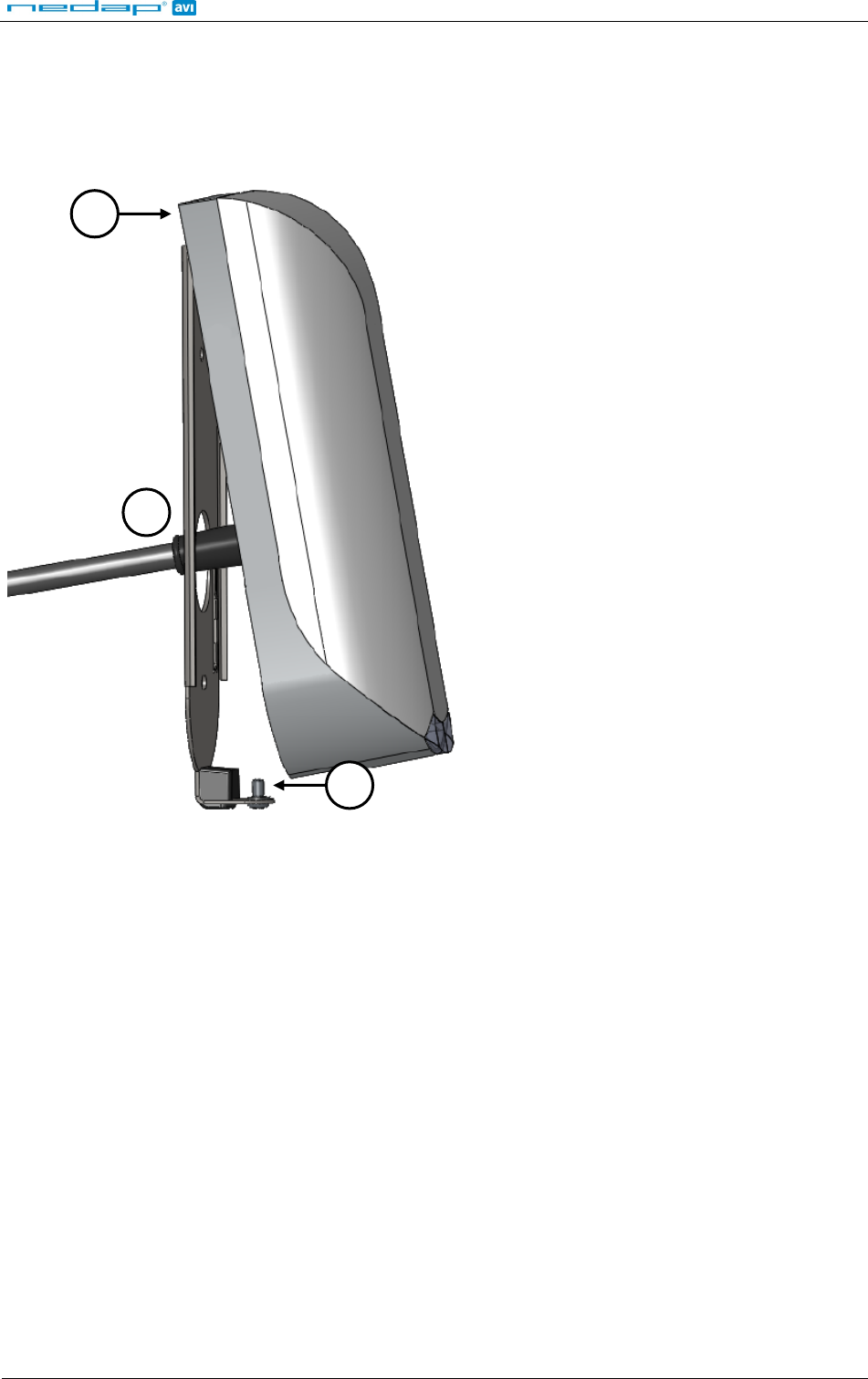
Install the uPASS Access reader onto the base-plate.
1. Feed the cable through the cable entry hole. Important note: minimum bending radius 30mm.
2. Attach the top of the uPASS Access onto the base-plate.
3. Fix the assembly using the screw on the bottom.
Figure 2: uPASS Access installation
1
2
3
uPASS Access
© Nedap AVI Page 8 of 19
3 CONNECTIONS
The uPASS Access is supplied with a 5 meter (15 feet) shielded cable pigtail with 12 multi-color wires.
RED
Power supply 12 - 24VDC.
BLACK
Power supply 0VDC, DC-Ground.
BROWN
RS485 A-
GREEN
RS485 A+
GRAY
Data-0 / Clock
PINK
Data-1 / Data
YELLOW
Tamper switch (normally closed)
GRY/PNK
Tamper switch (common)
RED/BLU
Led_UL_IN*
WHITE
Led_NA_IN*
PURPLE
Nedap antenna interface. RFMOD antenna modulation. Connect to ANT.
BLUE
Beeper_IN*
SHIELD
Shield
Note: Cable shield shall be connected to the metal case of the external device(s).
Cable extensions shall only be made by means of shielded cable(s).
All shields of the shielded cable extensions shall be connected together and to the metal case of the external
device(s).
Led_UL_IN*, Led_NA_IN* and Beeper_IN* are inputs that are active LOW.
uPASS Access
© Nedap AVI Page 9 of 19
3.1 POWER SUPPLY
The uPASS Access requires DC power supply in the range from 12 – 24V.
Maximum current consumption is 1A @ 12VDC, 0.5A @ 24VDC.
Connections:
RED
Power supply 12 - 24VDC.
BLACK
Power supply 0V / DC-ground.
SHIELD
Shield connected to DC-ground .
Note: Extending this connection beyond the 5 meter pig tail length shall ONLY be allowed using shielded cable.
The minimum voltage at the end of the fixed shieled pigtail cable shall be greather then 12VDC -10%
The shield shall be connected to the metal case of the external device.
3.2 COMMUNICATION
3.2.1 RS485
The uPASS Access reader has a RS485 interface for communication with a host system or for configuring reader
settings. The RS485 interface is a 2-wire half-duplex serial communication interface using balanced lines.
Connections:
BROWN
RS485 A- Balanced RX/TX
GREEN
RS485 A+ Balanced RX/TR
SHIELD
Shield connected to DC-ground.
Note: The RS485 interface is disabled while the USB interface is in use!
Extending this connection beyond the 5 meter pig tail length shall ONLY be allowed using shielded twisted pair
cable(2 x 2 x 0.25 mm2
The second twisted pair shall be used for the DC power supply.
) as long as the total length is shorter then 1200 meters, 6000 feet, cable capacity < 100
pF/meter.
The shield shall be connected to the metal case of the external device.
3.2.2 USB
The uPASS Access reader features an USB interface for service, installation and firmware upgrade purposes. The
Mini-USB connector is located on the bottom of the device and can only be reached when the bottom screw is
opened and the uPASS Access is lifted away from the base-plate. This ensures that unauthorized modifications
to the reader settings can be detected using the tamper switch.
The USB interface can be used to configure the reader using the UHFTOOL software.
Note: While the shielded USB cable is connected, the RS485 interface is disabled!
The maximum shielded cable length shall be < 2 meter.
USB Driver installation
Make sure your computer is connected to the internet. The driver should install automatically via Windows
update when the uPASS Access reader is connected to your PC via the USB cable. Follow the driver installation
wizard. If you do not see the Windows update pop-up, you can manually install the driver. To manually install,
you need to go to FTDI’s website at www.ftdichip.com/Drivers/VCP.htm and download the VCP (Virtual Com
Port) drivers for your operating system. Drivers for MacOS and Linux are available as well.
uPASS Access
© Nedap AVI Page 10 of 19
3.2.3 WIEGAND / MAGSTRIPE
The wiegand interface connections also support magstripe.
NEDAP UHF Wiegand tags will generate a wiegand message on the interface.
NEDAP UHF Magstripe tags will generate a magstripe message on the interface.
Other UHF tags will not generate a message on this interface, unless the 'Extra output' settings are used!
The wiegand/magstripe output format is determined by the programmed format of the tag.
Make sure to order the correct tag formatting if you want to use the wiegand or magstripe interface. See also the
UHF tags order guide for more information.
Connections:
Wiegand connections Magstripe connections
GRAY
Data-0 Clock
PINK
Data-1 Data
BLACK
Ground Ground
SHIELD
Shield connected to DC-ground.
Note: Extending these connections beyond the 5 meter pig tail length shall ONLY be allowed using shielded cable (4 x
0.25 mm2
The shield shall be connected to the metal case of the external device.
) as long as the total length is shorter then 150 meters (500 feet).
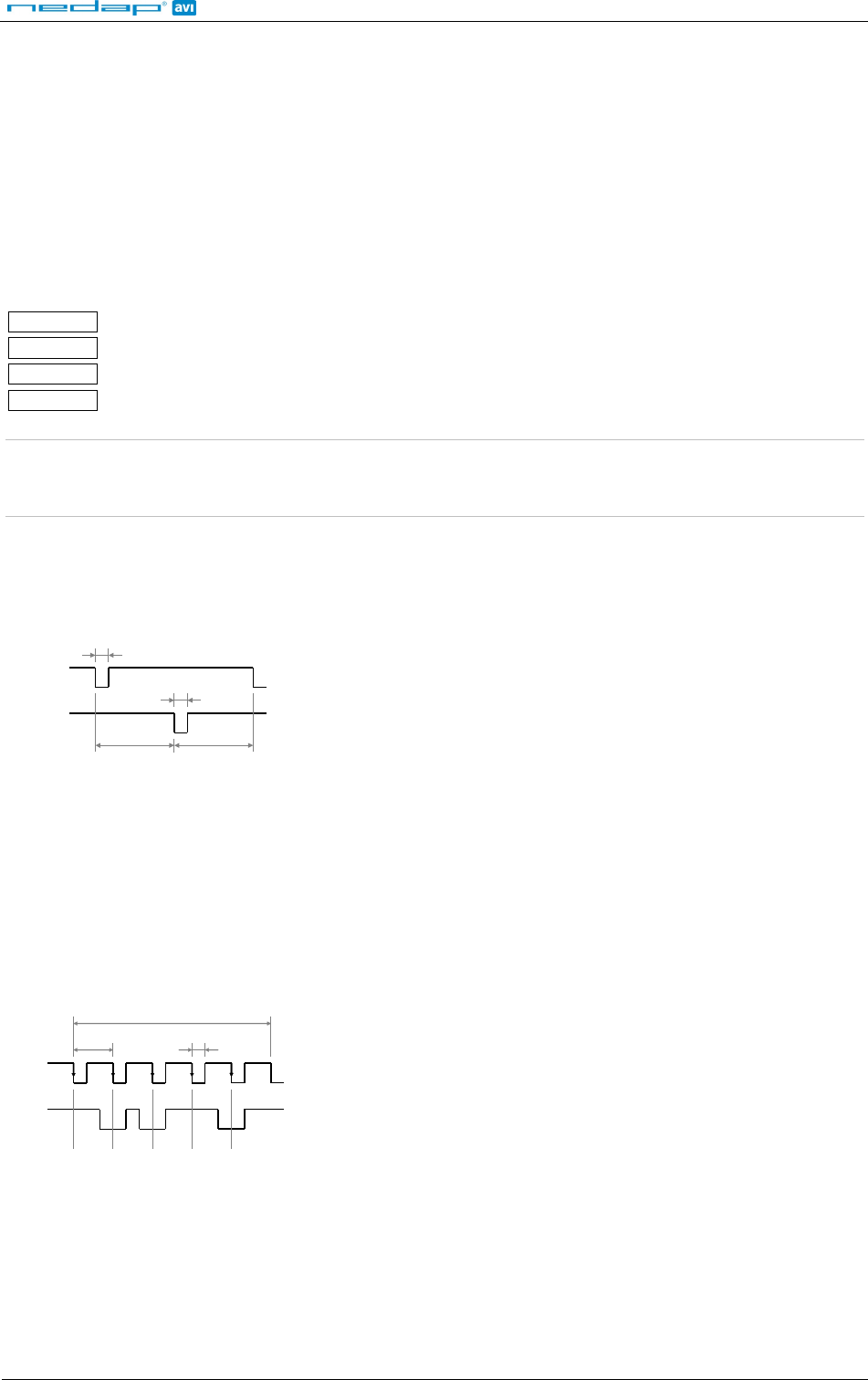
3.2.3.1 WIEGAND TIMING
In the figure below the Wiegand protocol timing is specified.
Tpw
5V
0V
DATA-1
5V
0V
DATA-0
Tpi
Tpi
Tpw
Timing constants:
Tpi Pulse interval time 1msec
Tpw Pulse width time 50µsec
Figure 3: Wiegand protocol timing
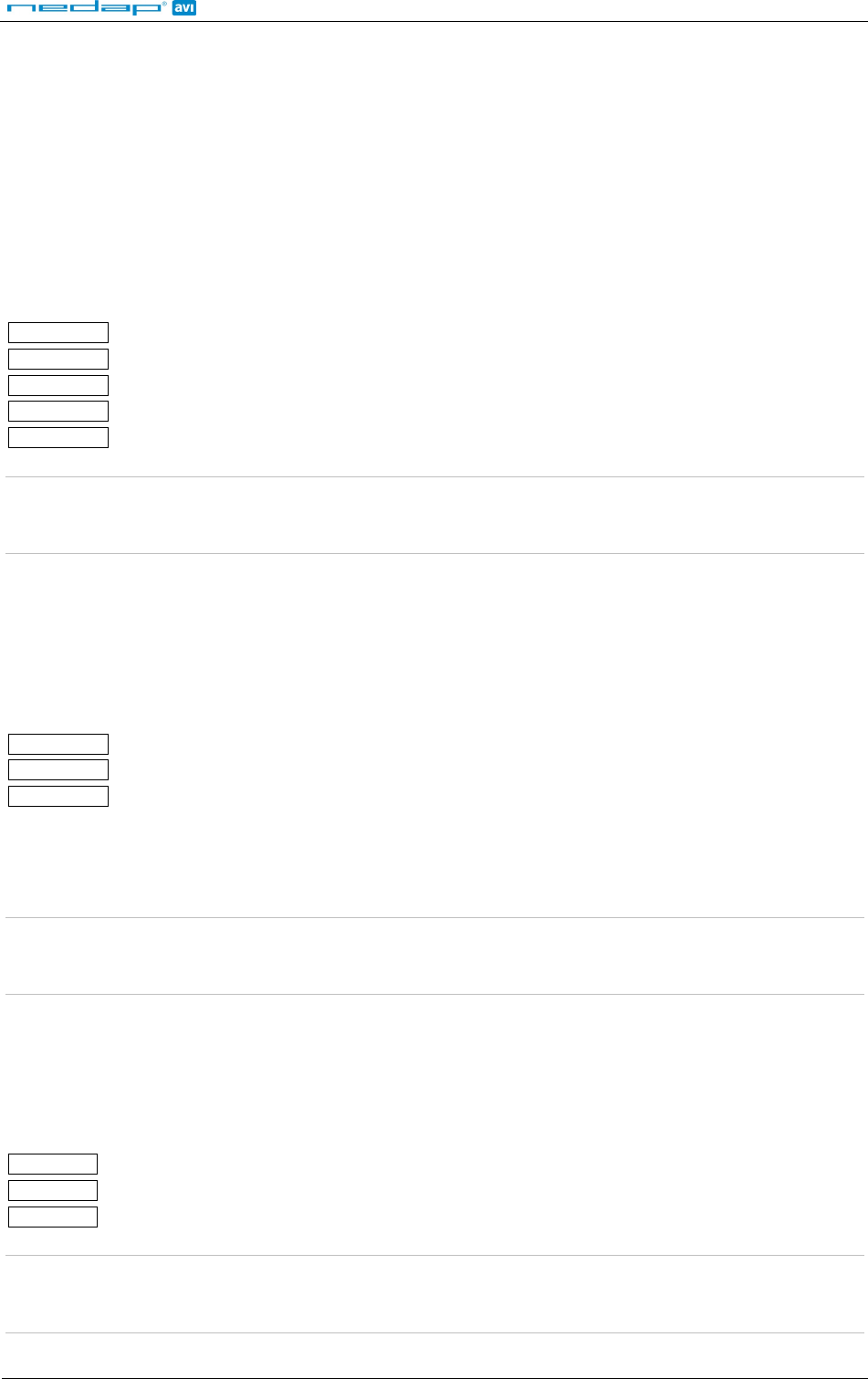
3.2.3.2 MAGSTRIPE TIMING
The magstripe message length is determined by the tag. The first character will be a start-sentinel (0xB). The
message is terminated with an end-sentinel character (0xF) and an LRC character.
The figure below shows the timing for one magstripe character. Each bit consists out of one period low
(220µsec) and two periods high (440µsec). The Data-signal is valid and stable on the falling edge of the Clock-
signal. Before and after the data 16 clock pulses are generated (postamble and preamble).
odd parity
msb
lsb
3300µsec
0
1
1
0
1
220µsec
660µsec
5V
0V
CLK
5V
0V
DAT
Timing constants:
Clock period 660µsec
Clock high 440µsec
Clock low 220µsec
Data pre-amble 16 clock periods
Data post-amble 16 clock periods
Figure 4: Magstripe protocol timing one character
uPASS Access
© Nedap AVI Page 11 of 19
3.3 LED CONTROL
The built-in high intensity LED provides visual feedback that the tag has been read or authorized. The LED and
buzzer can be controlled by the access control system.
Automatic mode:
Default the uPASS Access will automatically control the LED.
During stand-by the LED will be RED and upon identification it will be GREEN. These colors can be changed!
Remote control:
The LED can be controlled remotely by a connected access control system. Digital inputs will determine the
color indicated on the LED. Use UHFTOOL to enable the Remote LED control mode.
RED/BLU
Led_UL_IN*
WHITE
Led_NA_IN*
BLUE
Beeper_IN*
BLACK
Ground
SHIELD
Shield connected to DC-ground.
Note: Extending these connections beyond the 5 meter pig tail length shall ONLY be allowed using shielded cable (4 x
0.25 mm2
The shield shall be connected to the metal case of the external device.
) as long as the total length is shorter then 150 meters (500 feet).
3.4 TAMPER SWITCH
An internal magnet provides tamper indication when the reader is dismounted. This contact may be connected
to an external alarm system. The contacts are normally closed when the reader is in place.
Tamper switches of multiple readers can be connected in series.
Connections:
YELLOW
Tamper switch (normally closed)
GRY/PNK
Tamper switch (common)
SHIELD
Shield connected to DC-ground.
Contact ratings:
Max. current 50 mA (0.5 Volt voltage drop)
Max. switching voltage +24 VDC
Note: Extending this connection beyond the 5 meter pig tail length shall ONLY be allowed using shielded cable (2 x 0.25
mm2
The shield shall be connected to the metal case of the external device.
) as long as the total length is shorter then 150 meters (500 feet).
3.5 NEDAP ANTENNA INTERFACE
The Nedap antenna interface is used to connect the uPASS Access to NEDAP AEOS access control hardware such
as the AP1001. Instead of proximity antenna the uPASS Access can be connected.
Connections:
PURPLE
Nedap antenna interface. RFMOD antenna modulation. Connect to ANT.
BLACK
Nedap antenna interface. Ground, shield. Connect to ANT GND.
SHIELD
Shield connected to DC-ground.
Note: Extending this connection beyond the 5 meter pig tail length shall ONLY be allowed using coaxial cable, RG58U,
as long as the total length is shorter then 100 meters (350 feet).
The shield shall be connected to the metal case of the external device.
uPASS Access
© Nedap AVI Page 12 of 19
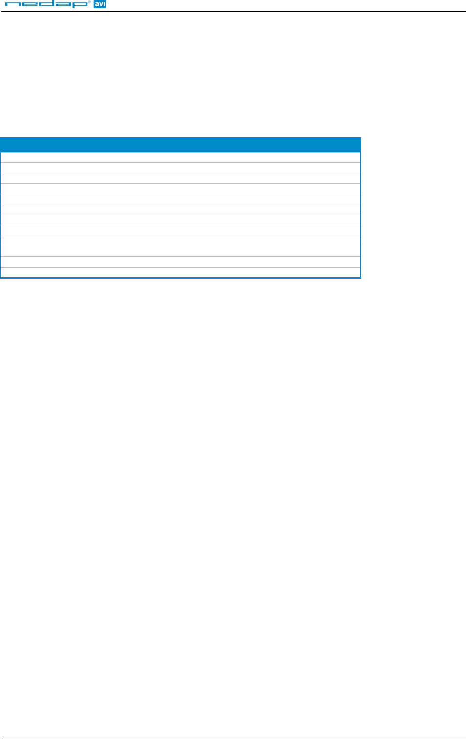
4 UHF FREQUENCIES
4.1 RADIO REGULATIONS
The uPASS Access reader operates on the 860 – 960 MHz band. Regulations in this band are not standardized
world-wide. Generally the regulations can be divided into several regions.
Per region a specific frequency band is available. This frequency band is divided into frequency channels. If local
radio regulations require frequency hopping (FHSS), then the uPASS Access automatically selects and uses the
available channels.
Region Technique Frequency Channels
Europe 865.6 - 867.6 MHz 4
Americas FHSS 902.7 - 927.2 MHz 52
Brazil
FHSS
915.5 - 927.5 MHz
43
China FHSS 920.5 - 924.5 MHz 20
Australia FHSS 920.7 - 925.2 MHz 12
Israel 915.0 - 917.0 MHz 4
Korea FHSS 917.7 - 920.1 MHz 5
New Zealand FHSS 917.7 - 920.1 MHz 8
Japan 917.3 - 920.3 MHz 6
Malaysia 919.8 - 922.2 MHz 5
Taiwan FHSS 922.6 - 927.4 MHz 9
Vietnam 920.7 - 924.3 MHz 7
Table 1: Region specific parameters
4.2 FREQUENCY CHANNEL SELECTION
If no frequency hopping is required, you should select an available frequency channel manually. This can be
realized as described below. Select an available frequency channel to achieve the best performance and to avoid
interference from other readers or equipment.
Use UHFTOOL to setup the frequency channel selection.
uPASS Access
© Nedap AVI Page 13 of 19
5 READER CONFIGURATION
The uPASS reader settings can be configured easily using the UHFTOOL software. Software developers can find
the communication protocol description in the firmware manual.
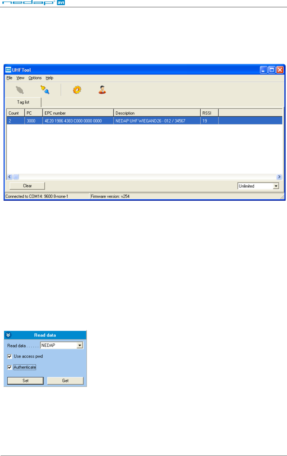
5.1 UHFTOOL SOFTWARE
Figure 5: UHFTOOL software
5.2 SETTINGS
Click 'View', 'Show config sidebar' or press F11 to show the configuration sidebar. In the sidebar the
configuration categories are shown. Expand or collapse the setting panels by clicking on it.
5.2.1 READ DATA
Configure here which tags should be selected, how to access these tags, what data should be read from these
tags and if a security check should be performed.
By default the reader is configured to select ANY TAG and read its EPC number.
Select NEDAP to read only Nedap tags.
NEDAP DUAL-ID (introduced in firmware version 2.29) enables the uPASS to search for Nedap vehicle-id tags.
When a vehicle-id tag is found, the uPASS searches for driver-id tags.
Example 1: Read only NEDAP UHF tags and use two way authentication:
Figure 6: Read data example 1
uPASS Access
© Nedap AVI Page 14 of 19
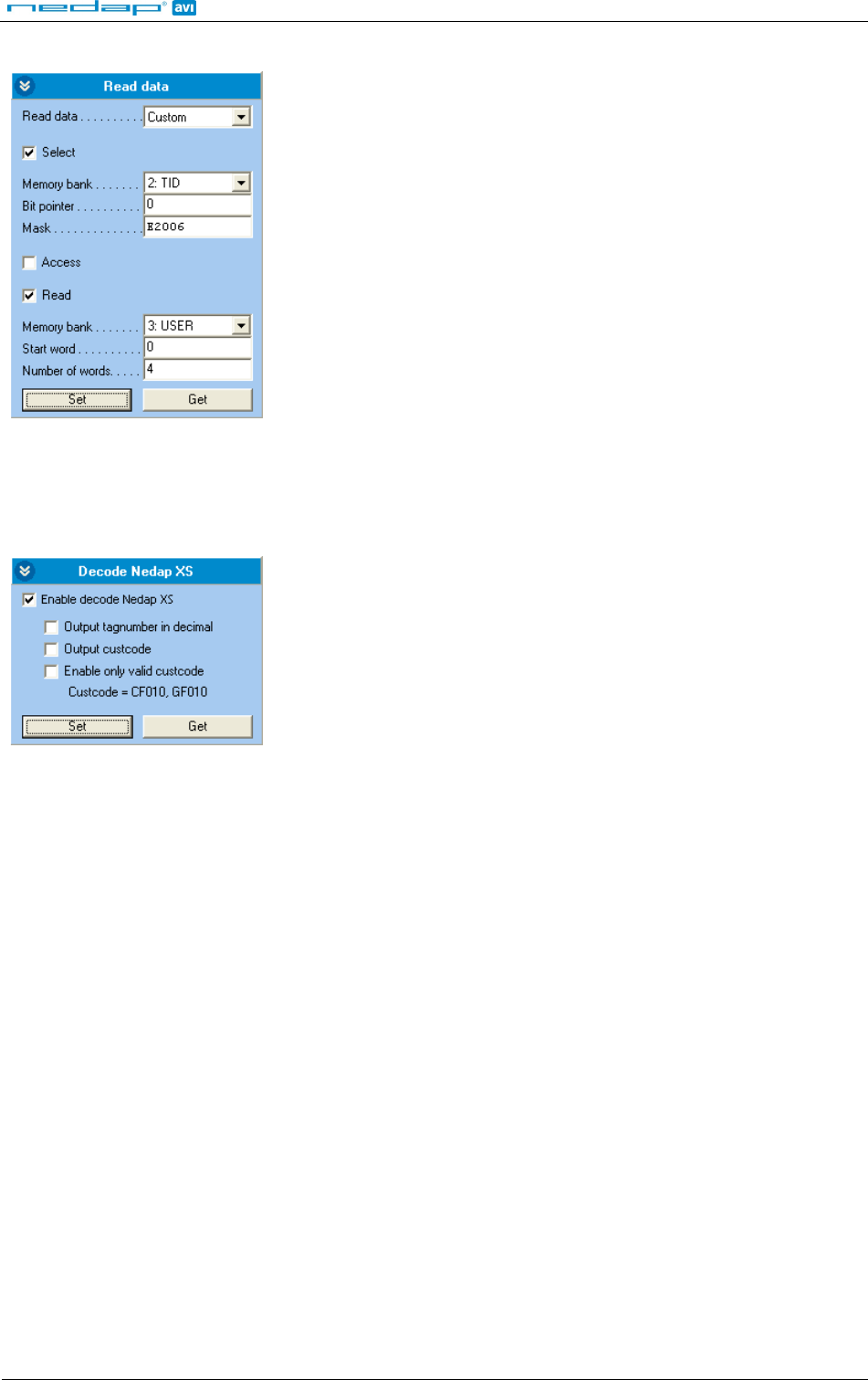
Example 2: Read only NXP UCODE tags (TID starts with E2006) and read 4 words from user memory.
Figure 7: Read data example 2
5.2.2 DECODE NEDAP XS
Enable decode Nedap XS formatted tags. Introduced in firmware version 2.54.
Figure 8: Output settings
By default the data on NEDAP XS formatted tags will be transmitted to the TRANSIT compatible processor or the
the NEDAP antenna modulation interface. In this case the UPASS will not perform any decoding.
Enable decode Nedap XS when you do not want to use the TRANSIT compatible processor or the antenna
modulation interface. The UPASS will decode the NEDAP XS tag data and output its plain tag-number. You can
also enable to output or verify the customer code.
The decoded NEDAP XS output number contains:
Byte 1: 4E NEDAP UHF
Byte 2: <FMT> FMT=01: Nedap XS decoded hex tagno
FMT=02: Nedap XS decoded decimal tagno.
Byte 3-4: 00 Unused
Byte 5-7: CC CC=Customer code (zero if not transmitted)
Byte 8-12: TAGNO TAGNO=Tag number
Examples:
NEDAP UHF XS: Output: 4E10 3FFF C415 A87C BD51 8000
NEDAP UHF XS decoded: Output: 4E01 0000 0000 0000 0000 3039
NEDAP UHF XS decoded decimal: Output: 4E02 0000 0000 0000 0001 2345
NEDAP UHF XS decoded + custcode: Output: 4E01 0000 0415 A000 0000 3039
NEDAP UHF XS decoded decimal + custcode: Output: 4E02 0000 0415 A000 0001 2345
uPASS Access
© Nedap AVI Page 15 of 19
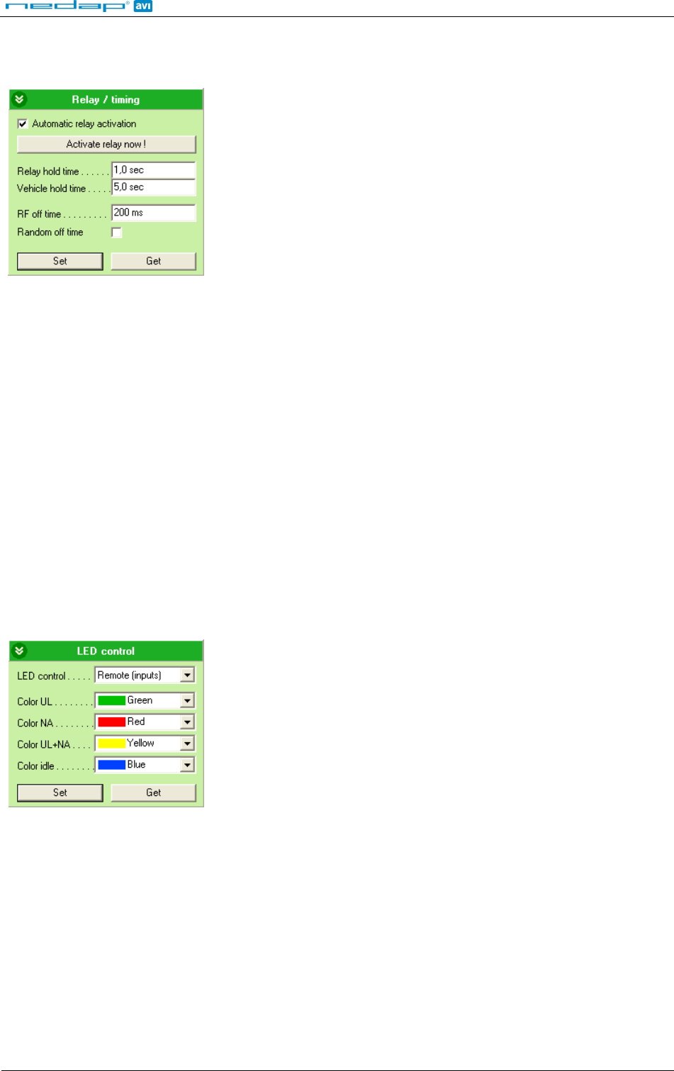
5.2.3 RELAY / TIMING
Configure relay output and timing parameters.
Figure 9: Relay / timing settings
Enable 'Automatic relay activation' to activate the relay upon identification. When disabled the relay can only be
activated manually.
The 'Relay hold time' setting is the minimum time the relay is activated.
The 'Vehicle hold time' setting is the time, after a vehicle-id tags has been found, for which the reader will search
for driver-id tags. This setting is only used in the NEDAP DUAL-ID mode. Introduced in firmware version 2.29.
The (random) RF off time parameter can be used to enable time sharing between multiple readers on the same
frequency.
5.2.4 LED CONTROL
Only for UPASS ACCESS: setup LED control mode.
Automatic mode:
Default the uPASS Access will automatically control the LED.
During stand-by the LED will be BLUE and upon identification it will be GREEN. These colors can be changed!
Figure 10: LED control
Remote control:
The LED can be controlled remotely by a connected access control system. Digital inputs will determine the
color indicated on the LED.
uPASS Access
© Nedap AVI Page 16 of 19
5.3 EXPERT SETTINGS
Click 'Options', 'Usermode', 'Expert' to show additional configuration settings for advanced users.
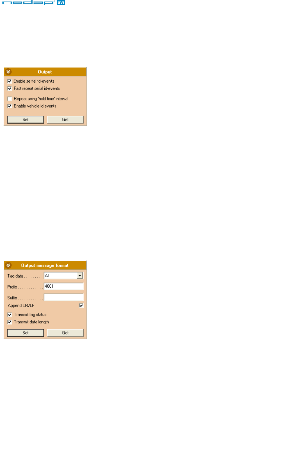
5.3.1 OUTPUT
Configure communication output settings.
Figure 11: Output settings
Select 'Enable serial id-events' to enable the serial output upon identification. Only disable the serial id-events to
optimize the identification speed when using the wiegand or magstripe interface or the TRANSIT compatible
processor.
When 'Fast repeat serial id-events' is selected (default) the serial output is repeated upon every identification.
When this option is disabled, the message is only sent once.
Enable 'Repeat using hold-time interval' to repeat id-events with hold-time interval. The repeating will be
enabled for the serial and also for the wiegand or magstripe interface.
'Enable vehicle id-events' allows enabling or disabling the id-event messages for vehicle-ids. This may be useful
in combination with the NEDAP DUAL-ID mode and an access control panel that does not support the dual-id
feature.
5.3.2 OUTPUT MESSAGE FORMAT
Configure output message format.
Figure 12: Output message format
The output message format is configurable:
<prefix> [<tagstatus>] [<epclen>] [<epc>] [<datlen>] [<data>] <suffix> [ CR/LF ]
Note: When the output message format is changed, identified tags may no longer be shown in the UHFTOOL.
uPASS Access
© Nedap AVI Page 17 of 19
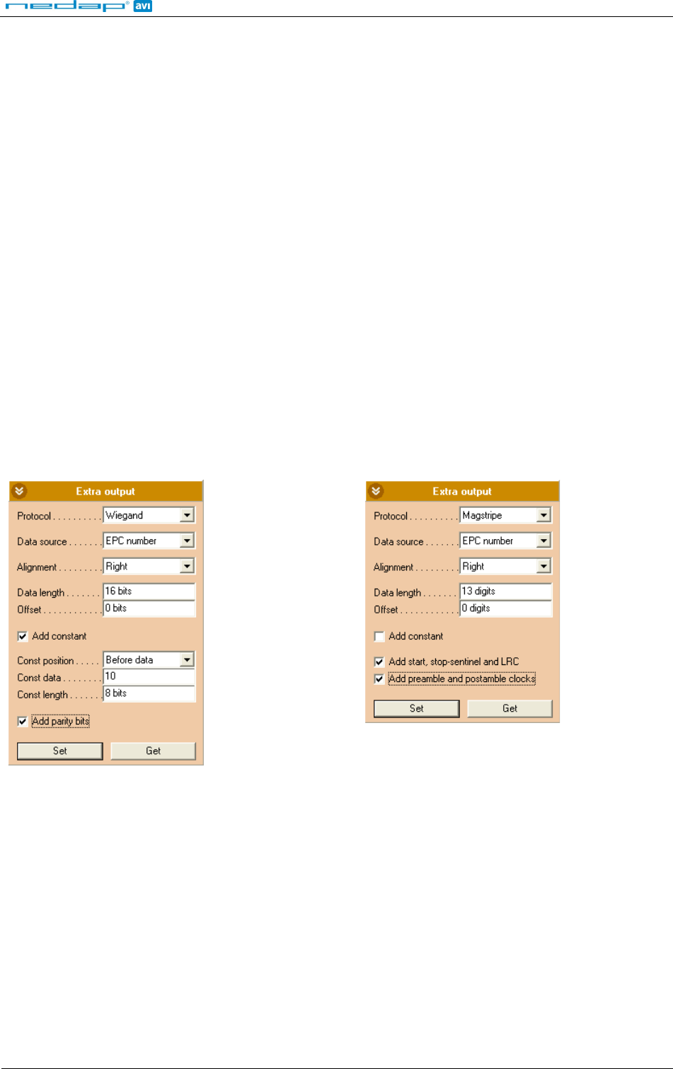
5.3.3 EXTRA OUTPUT
Optionally enable wiegand or magstripe output for tags that are not programmed by Nedap in a wiegand,
magstripe or nedap-xs format. This feature is introduced in firmware version 2.13 or newer.
'Protocol':
Disabled Do not use the additional output feature.
Wiegand Enable additional wiegand output.
Magstripe Enable additional magstripe output.
'Data source':
EPC number Output the EPC number using the selected protocol.
Custom read data Output the custom data read using the selected protocol.
See for more information about how to setup custom read data chapter 5.2.1.
'Alignment':
Full Use the complete EPC number (or all custom read data).
Left Truncate data. Keep left.
Right Truncate data. Keep right.
'Data length': Data length in bits for wiegand (or in digits for magstripe).
'Offset': Data offset in bits for wiegand (or in digits for magstripe).
'Add constant': Enable to add a constant to the output before or after the data read from the tag.
Example 1: Output a wiegand 26-bit message with
facility code 10:
Figure 13: Additional output example 1
Example 2: Output the 13 rightmost digits from the
EPC number using the magstripe interface:
Figure 14: Additional output example 2
uPASS Access
© Nedap AVI Page 18 of 19
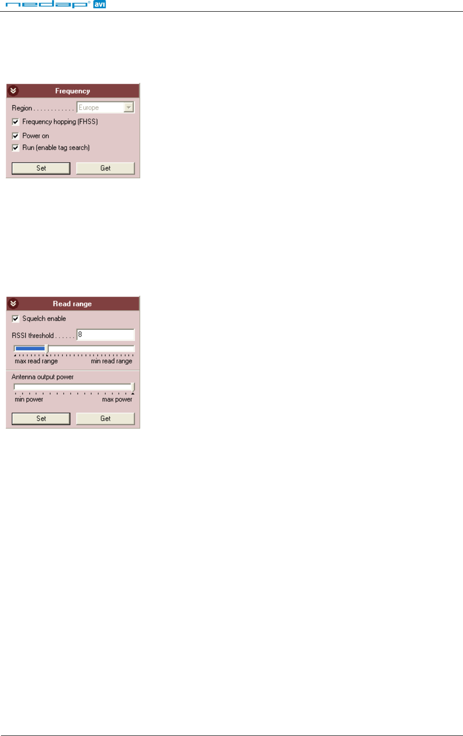
5.3.4 FREQUENCY
Here is shown the reader's operating frequency region.
Only for systems that do not use frequency hopping (e.g. in Europe):
You can select a frequency channel within the available frequency band.
Figure 15: Frequency
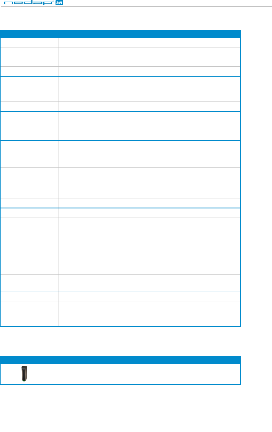
5.3.5 READ RANGE
Enable the squelch to reduce the read range. This is useful to optimize lane separation.
When the squelch is enabled, you can set the squelch level. This level ensures that only tags with a returned
signal strength higher then the squelch level are identified.
When the squelch is enabled and the returned signal strength is lower then the squelch level, the SQ-ACT LED
indicates that the tag is rejected.
Figure 16: Read range
uPASS Access
© Nedap AVI Page 19 of 19
A TECHNICAL SPECIFICATIONS
ITEM SPECIFICATION REMARK
Dimensions 150x50x40mm (5.9 x 1.9 x 1.5 inch)
Weight 0.5 kg (1.1 lbs)
Enclosure Polycarbonate (RAL7016)
Chassis material Aluminum (Zamak5) (RAL9006)
Protection class IP65 (Approx. NEMA4x)
Operational
temperature -30 °C … + 60 °C (-22°F … +140°F)
Relative humidity 10 .. 93 % non condensing
Identification range Up to 2 meters (Line Off Site) (6 feet) With passive NEDAP UHF tags
Power supply 12 … 24VDC ±10% linear power supply
Current consumption 1A @ 12VDC, 0.5A @ 24VDC
Inputs 2 digital input for LED control
1 digital input for buzzer control Active low inputs
Tamper indication Yes by tamper switch Dry contact
Output Wiegand, magstripe (clock & data)
Cable Fixed shielded cable length of 5 meter (16 feet)
included Cable extensions beyond the 5
meter shall ONLY be allowed
using shielded cable
Interfaces RS485 and USB USB local service only
Air interface ISO18000-6C
Operating frequency
Europe: 865 … 868 MHz
Americas: 902 … 928 MHz (FHSS)
Brazil: 915 … 928 MHz (FHSS)
China: 920 … 928 MHz (FHSS)
Australia: 920 … 926 MHz (FHSS)
Polarization Horizontal + Vertical Switched every query round
ERP / EIRP < 1 W (30 dBm) ERP (CE)
< 4 W (36 dBm) EIRP (FCC)
Safety EN 60950
Emission EN 302 208-1,-2 v1.3.1
FCC part 15.247 incl. Spread Spectrum
Industry Canada RSS210
B PART NUMBERS
READERS
NEDAP uPASS Access (EUR)
NEDAP uPASS Access (USA) part number: 9958240
part number: 9206663