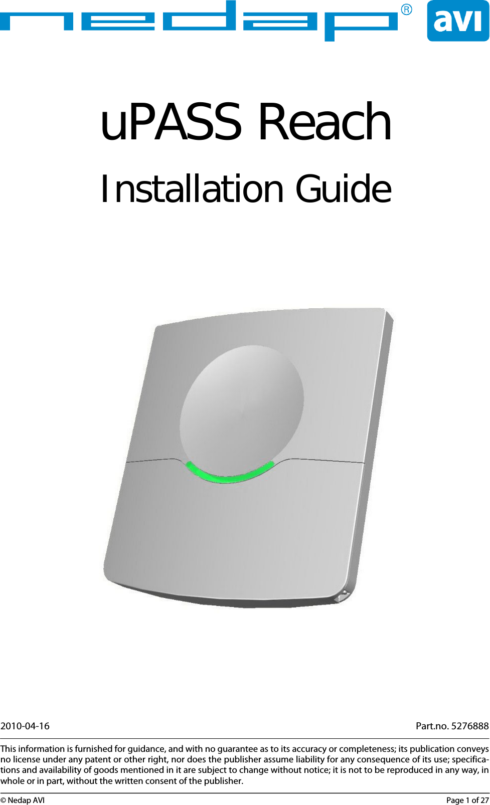
Nedap N V UPASSREACH UHF RFID Reader for EPC Gen2 Class 1 tags User Manual uPASS Reach
N. V. Nederlandsche Apparatenfabriek NEDAP UHF RFID Reader for EPC Gen2 Class 1 tags uPASS Reach
UserManual.wiki
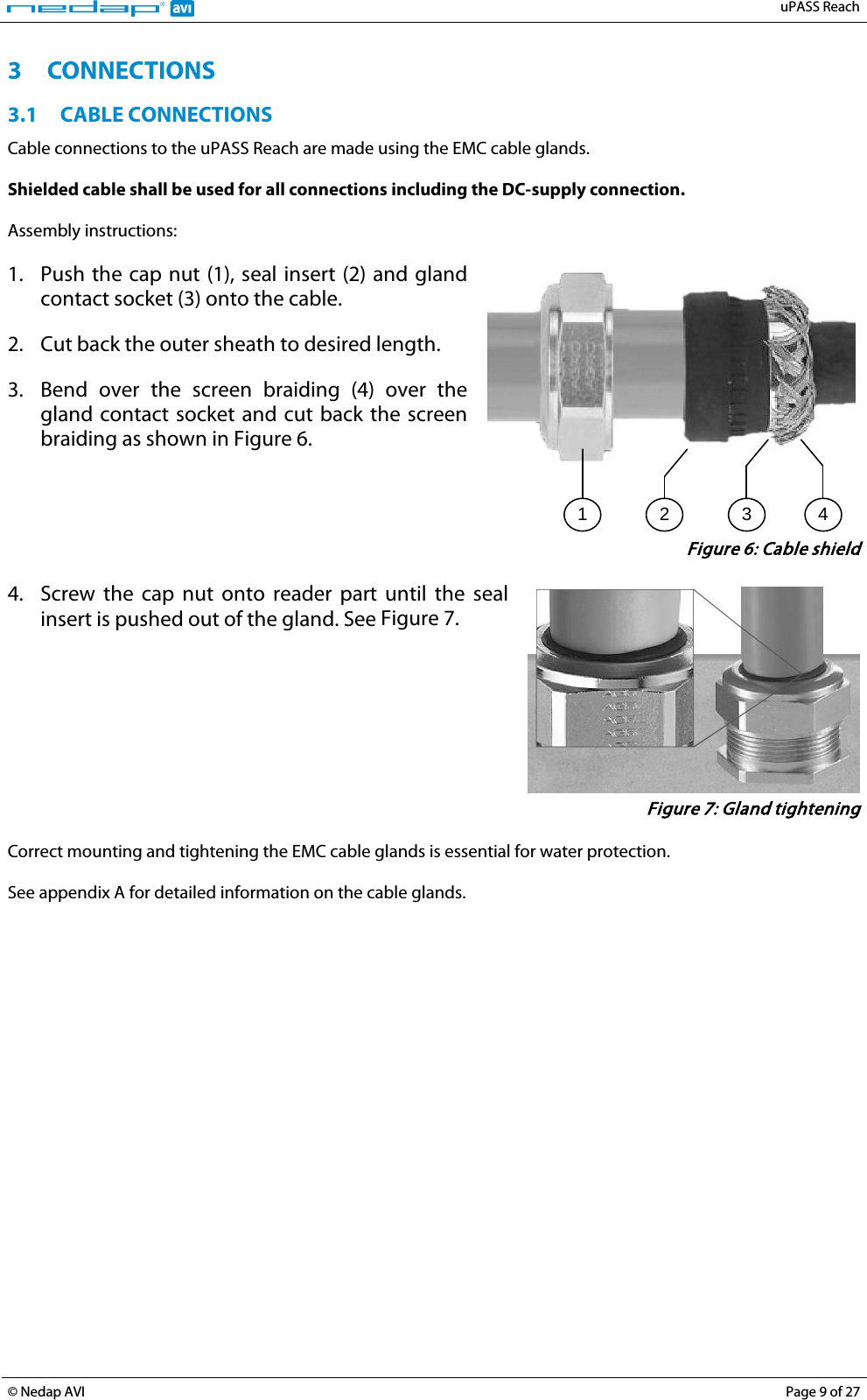
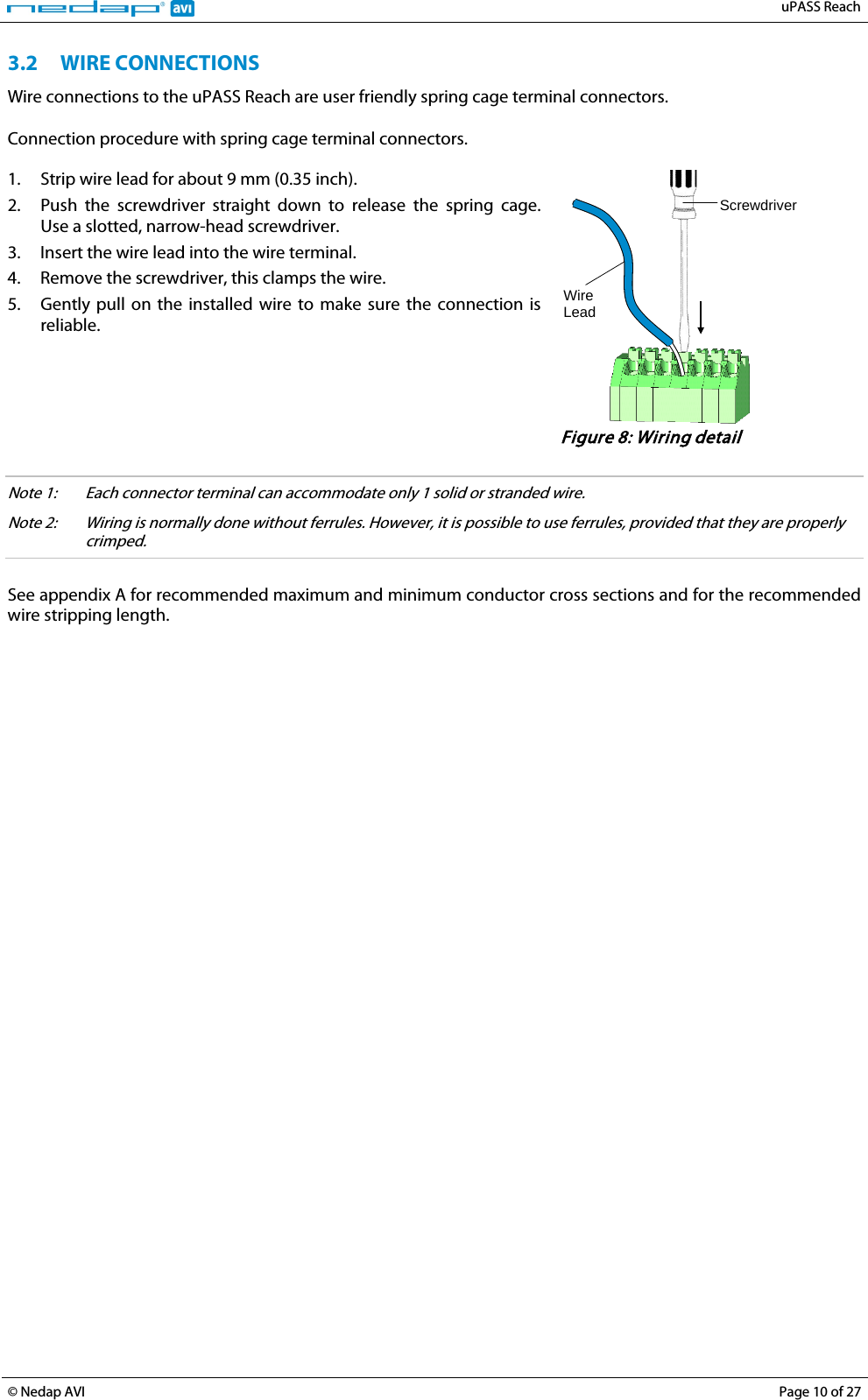
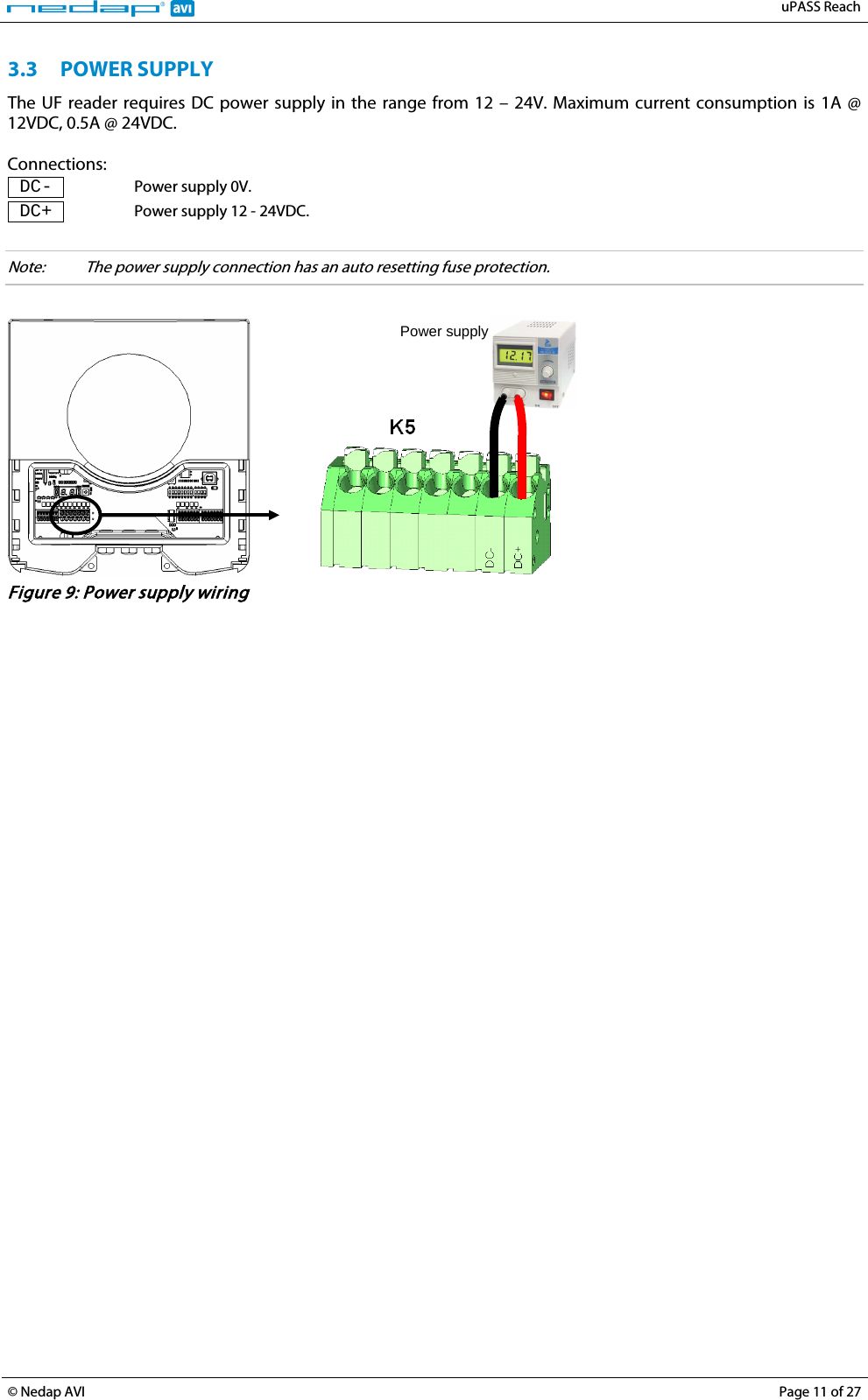
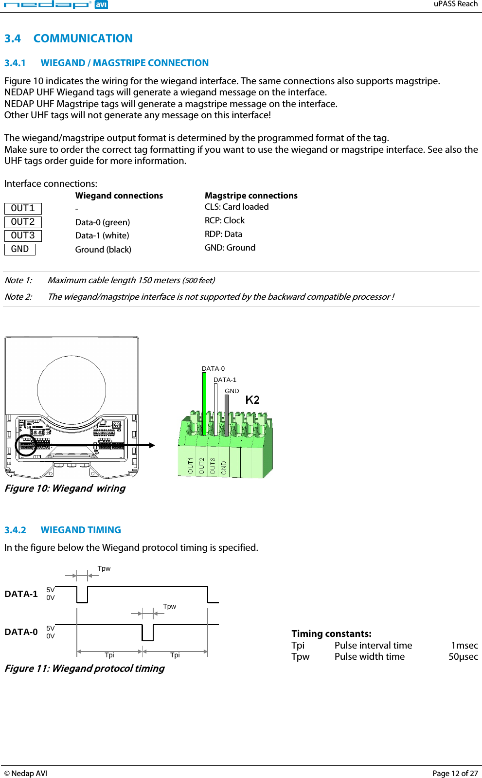
>
Nedap N V
>
UPASSREACH User Manual
>
user manual
Contents
1.
datasheet1
2.
datasheet2
3.
user manual
user manual
Navigation menu
Upload a User Manual
Namespaces
Wiki Guide
HTML
PDF
Info
Views
User Manual
Discussion / Help
Navigation