Nedap N V UPASSREACH UHF RFID Reader for EPC Gen2 Class 1 tags User Manual uPASS Reach
N. V. Nederlandsche Apparatenfabriek NEDAP UHF RFID Reader for EPC Gen2 Class 1 tags uPASS Reach
Contents
- 1. datasheet1
- 2. datasheet2
- 3. user manual
user manual
2010-04-16 Part.no. 5276888
This information is furnished for guidance, and with no guarantee as to its accuracy or completeness; its publication conveys
no license under any patent or other right, nor does the publisher assume liability for any consequence of its use; specifica-
tions and availability of goods mentioned in it are subject to change without notice; it is not to be reproduced in any way, in
whole or in part, without the written consent of the publisher.
© Nedap AVI Page 1 of 27
uPASS Reach
Installation Guide

uPASS Reach
© Nedap AVI Page 2 of 27
FCC ID: CGDUPASSREACH
IC: 1444A-UPASSRCH
This device complies with part 15 of the FCC rules and to RSS210 of Industrial Canada. Operation is subject to the
following two conditions: (1) this device may not cause harmful interference, and (2) this device must accept any
interference received, including interference that may cause undesired operation.
Changes or modifications not expressly approved by the party responsible for compliance could void the user's
authority to operate the equipment.
This equipment complies with FCC RF radiation exposure limits set forth for an uncontrolled environment.
This device shall be installed to provide a separation distance of at least 20 cm from all persons.

uPASS Reach
© Nedap AVI Page 3 of 27
CONTENTS
1 INTRODUCTION ....................................................................................................................................................................................... 4
1.1 OVERVIEW ....................................................................................................................................................................................... 4
1.2 SUPPORTED TAGS ........................................................................................................................................................................ 5
1.3 TAG SECURITY ................................................................................................................................................................................ 5
2 INSTALLATION ......................................................................................................................................................................................... 6
2.1 SAFETY INSTRUCTION ................................................................................................................................................................. 6
2.2 MOUNTING INSTRUCTIONS ...................................................................................................................................................... 6
2.3 ADJUSTABLE MOUNTING BRACKET ...................................................................................................................................... 7
2.4 OPENING THE SERVICE COVER ................................................................................................................................................ 8
1T3 CONNECTIONS ......................................................................................................................................................................................... 9
3.1 CABLE CONNECTIONS ................................................................................................................................................................ 9
3.2 WIRE CONNECTIONS ................................................................................................................................................................ 10
3.3 POWER SUPPLY .......................................................................................................................................................................... 11
3.4 COMMUNICATION .................................................................................................................................................................... 12
3.4.1 WIEGAND / MAGSTRIPE CONNECTION ............................................................................................................... 12
3.4.2 WIEGAND TIMING ....................................................................................................................................................... 12
3.4.3 MAGSTRIPE TIMING .................................................................................................................................................... 13
3.4.4 RS232 CONNECTION .................................................................................................................................................. 14
3.4.5 RS422 CONNECTION .................................................................................................................................................. 15
3.4.6 USB CONNECTION ....................................................................................................................................................... 16
3.5 DIGITAL I/O .................................................................................................................................................................................. 17
3.5.1 RELAY OUTPUT ............................................................................................................................................................. 17
3.5.2 READ DISABLE INPUT ................................................................................................................................................. 18
3.5.3 GENERAL PURPOSE INPUTS ..................................................................................................................................... 18
3.5.4 TAMPER SWITCH .......................................................................................................................................................... 19
1T4 DIP-SWITCH SETTINGS ....................................................................................................................................................................... 20
4.1 COMPATIBILITY MODE ............................................................................................................................................................ 20
4.2 RS232 / RS422 SELECTION ..................................................................................................................................................... 20
4.3 UNUSED SWITCHES .................................................................................................................................................................. 20
5 LED INDICATIONS ................................................................................................................................................................................ 21
6 UHF FREQUENCIES .............................................................................................................................................................................. 22
6.1 RADIO REGULATIONS .............................................................................................................................................................. 22
6.2 FREQUENCY CHANNEL SELECTION .................................................................................................................................... 22
7 READER CONFIGURATION ................................................................................................................................................................ 23
7.1 UHFTOOL SOFTWARE .............................................................................................................................................................. 23
7.2 SETTINGS ...................................................................................................................................................................................... 23
7.2.1 READ DATA .................................................................................................................................................................... 23
7.2.2 OUTPUT ........................................................................................................................................................................... 24
7.2.3 OPTIONS ......................................................................................................................................................................... 24
1T7.3 EXPERT SETTINGS ...................................................................................................................................................................... 25
7.3.1 FREQUENCY ................................................................................................................................................................... 25
7.3.2 SQUELCH ........................................................................................................................................................................ 25
A TECHNICAL SPECIFICATIONS ........................................................................................................................................................... 26
B PART NUMBERS .................................................................................................................................................................................... 27
uPASS Reach
© Nedap AVI Page 4 of 27
1 INTRODUCTION
The uPASS Reach reader offers long range vehicle identification up to 4 meters using the latest UHF technology.
Based on battery free passive UHF the uPASS Reach reader offers a cost effective and enduring solution for
parking access.
The system is based on a uPASS Reach reader and an UHF tag. The readers are installed next to the gate on a
maximum height of 2 meters. The reader is the perfect cure to the problems characteristic of prox and it's ideally
suited for upgrading those installations as the reader can easily be installed on a gooseneck with no need for
additional mounting or rewiring.
The reader output allows the access control or parking system to open the gate when authorized without the
need to present a badge. The built-in high intensity LED provides the user visual feedback that the tag has been
read.
1.1 OVERVIEW
The picture below shows a simplified overview of the components in the reader. The uPASS Reach reader
contains an UHF antenna, UHF processor and an additional backwards compatible processor.
Figure 1: uPASS Reach reader overview
The backwards compatible processor supports existing communication protocols already implemented for the
TRANSIT system. Therefore no additional integration effort is required.
Note: The backwards compatible processor only operates with NEDAP UHF XS formatted tags.
UHF processor
Backward
compatible
processor
(P61, Q70 etc)
UHF
antenna
Wiegand/Magstripe
UART UHF
UART PIC
USB
RS232
RS422
SW1-1
Auto detect USB
SW1-2
uPASS Reach
NEDAP XS
SW1-1
RELAY OUT
READ DISABLE
POWER SUPPLY

uPASS Reach
© Nedap AVI Page 5 of 27
1.2 SUPPORTED TAGS
Any EPC Class 1 Gen 2 tag is supported by the uPASS Reach.
NEDAP formatted UHF tags can have the following formats:
• NEDAP UHF Wiegand tags
These tags will contain all wiegand information including facility code and parity bits. All wiegand formats
can be supported. The reader transparantly sends this information via the wiegand outputs. There is no
need to change any DIP-switches or configuration settings. See chapter 3.4.1 for wiring details.
Note: The wiegand output format is determined by the tag and not by the reader.
• NEDAP UHF Magstripe tags
These tags will contain all magstripe information. The reader transparantly sends this information onto the
magstripe interface. There is no need to change any DIP-switches or configuration settings. See chapter 3.4.1
for wiring details.
Note: The magstripe output format is determined by the tag and not by the reader.
• NEDAP UHF XS tag
These tags are especially programmed in the same format as our 2.45GHz AVI tags (Compact-Tag, Window-
Button and Heavy-Duty-Tag). The tags will also have an customer-code and id-number. The reader will
automatically transmit the tag-info to the backward compatible processor.
Note: When using the backwards compatible processor make sure the compatiblity mode DIP-switch is
set correctly (see chapter 4.1 on page 20).
Non-nedap formatted EPC Class 1 Gen 2 tag are supported, but only using the RS232/422 or USB interface.
1.3 TAG SECURITY
EPC (Electronic Product Code) tags were introduced as a possible successor to the barcode with added
functionalities. The tag emits its EPC in plain text. This makes the tags vulnerable to cloning and counterfeiting
attacks. Unlike many 13MHz smartcards, EPC tags do not support any DES, 3DES or AES encryption.
EPC tags contain a data field known as the Tag Identifier (TID). At the discretion of the EPC manufacturer, the
value may be factory programmed and locked, ensuring that tags have a unique identity and (theoretically)
cannot be cross-copied. This TID based anti-cloning mechanism is not considered to be a strong protection.
NEDAP UHF tags support a locked serialized TID and the uPASS Reach reader can be configured to read the TID
data field.
In addition NEDAP has also implemented an advanced anti-cloning and anti-counterfeiting method based upon
a two way authentication. This feature is supported in combination with all NEDAP UHF tags. See also chapter 7.
By default the uPASS Reach reader is configured to read any EPC tag.
We encourage customers to enable the TID-check or the two way authentication. But also advise not to
completely rely on these methods in high-security applications.
uPASS Reach
© Nedap AVI Page 6 of 27
2 INSTALLATION
2.1 SAFETY INSTRUCTION
The following safety precautions should be observed during normal use, service and repair.
• All shields of the mandatory shielded cable shall be connected with safety ground.
• The uPASS Reach may only be installed and serviced by qualified service personnel.
• Disconnect the power supply before removing or installing any parts.
• To be sure of safety, do not modify or add anything to the uPASS Reach other than mentioned in this
installation guide or indicated by NEDAP N.V.
2.2 MOUNTING INSTRUCTIONS
The uPASS Reach can be mounted to any surface, including directly to metal. Locate an appropriate position. Use
the upper two keyholes (K) to mount the reader. Open the service cover to secure the reader using the two lower
mounting positions (L).
See the picture below for details about the dimensions and the locations of the mounting positions.
L
service cover
K
200mm (7.87"
)
47mm (1.85")
220mm (8.66")
108mm (4.25")
35mm
171mm (6.73")
(1.38")
63mm (2.48")
4.5mm (.17")
∅5mm
(.20")
∅4.5mm
(.17")
rear view
front view
side view
Figure 2: uPASS Reach reader dimensions
uPASS Reach
© Nedap AVI Page 7 of 27
2.3 ADJUSTABLE MOUNTING BRACKET
With the adjustable mounting bracket, the uPASS Reach can be ‘aimed’ at the desired detection area. It can also
be used for mounting the reader to round or square masts (see appendix B for part numbers).
Figure 3: Adjustable mounting bracket
Once the adjustable mounting bracket is assembled, attach the bracket to the wall or mast. After that the uPASS
Reach can be mounted onto the bracket. The ball and socket joint can be used to adjust the reader’s orientation.
Tighten the hex screw on top of the joint to fix the correct orientation.
Note: Maximum diameter for round masts 125mm (4.9 inch)
Maximum diameter for square masts 100mm (3.9 inch)
123mm (4.84")
47mm (1.85")
61mm (2.40")
120mm (4.72")
15mm
(.59")
88mm (3.46")
side view
rear view
∅4.5mm
(.17")
Figure 4: Adjustable mounting bracket dimensions (in mm)
uPASS Reach
© Nedap AVI Page 8 of 27
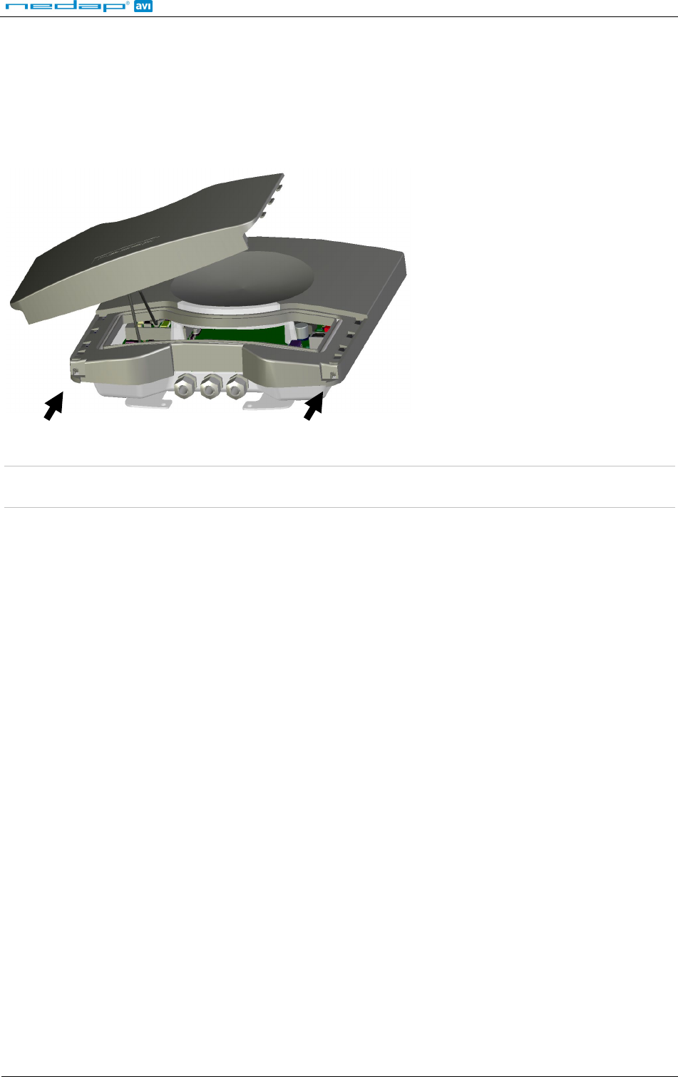
2.4 OPENING THE SERVICE COVER
The service cover can be opened to access the connections (including the USB connector), setup the operating
frequency and view the LED indicators.
Open the screws on the bottom of the device to unlock the service cover. Once the service cover is unlocked, lift
it off.
Figure 5: Opening the service cover
Note: Make sure the screws are completely opened (and closed when placing the cover back on). Don’t worry about
losing the screws, they cannot fall out.
uPASS Reach
© Nedap AVI Page 9 of 27
3 CONNECTIONS
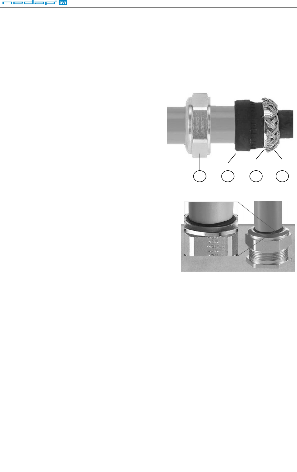
3.1 CABLE CONNECTIONS
Cable connections to the uPASS Reach are made using the EMC cable glands.
Shielded cable shall be used for all connections including the DC-supply connection.
Assembly instructions:
1.
Push the cap nut (1), seal insert (2) and gland
contact socket (3) onto the cable.
2. Cut back the outer sheath to desired length.
3. Bend over the screen braiding (4) over the
gland contact socket and cut back the screen
braiding as shown in Figure 6.
1
2
3
4
Figure 6: Cable shield
4.
Screw the cap nut onto reader part until the seal
insert is pushed out of the gland. See Figure 7.
Figure 7: Gland tightening
Correct mounting and tightening the EMC cable glands is essential for water protection.
See appendix A for detailed information on the cable glands.
uPASS Reach
© Nedap AVI Page 10 of 27
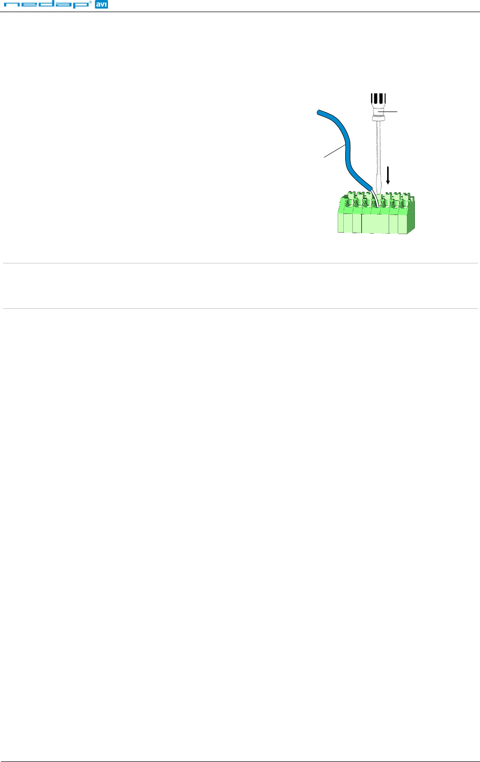
3.2 WIRE CONNECTIONS
Wire connections to the uPASS Reach are user friendly spring cage terminal connectors.
Connection procedure with spring cage terminal connectors.
1.
Strip wire lead for about 9 mm (0.35 inch).
2.
Push the screwdriver straight down to release the spring cage.
Use a slotted, narrow-head screwdriver.
3. Insert the wire lead into the wire terminal.
4. Remove the screwdriver, this clamps the wire.
5.
Gently pull on the installed wire to make sure the connection is
reliable.
Wire
Lead
Screwdriver
Figure 8: Wiring detail
Note 1: Each connector terminal can accommodate only 1 solid or stranded wire.
Note 2: Wiring is normally done without ferrules. However, it is possible to use ferrules, provided that they are properly
crimped.
See appendix A for recommended maximum and minimum conductor cross sections and for the recommended
wire stripping length.
uPASS Reach
© Nedap AVI Page 11 of 27
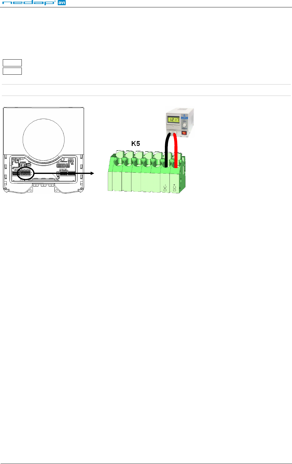
3.3 POWER SUPPLY
The UF reader requires DC power supply in the range from 12 – 24V. Maximum current consumption is 1A @
12VDC, 0.5A @ 24VDC.
Connections:
DC-
Power supply 0V.
DC+
Power supply 12 - 24VDC.
Note: The power supply connection has an auto resetting fuse protection.
Power supply
Figure 9: Power supply wiring
uPASS Reach
© Nedap AVI Page 12 of 27
3.4 COMMUNICATION
3.4.1 WIEGAND / MAGSTRIPE CONNECTION
Figure 10 indicates the wiring for the wiegand interface. The same connections also supports magstripe.
NEDAP UHF Wiegand tags will generate a wiegand message on the interface.
NEDAP UHF Magstripe tags will generate a magstripe message on the interface.
Other UHF tags will not generate any message on this interface!
The wiegand/magstripe output format is determined by the programmed format of the tag.
Make sure to order the correct tag formatting if you want to use the wiegand or magstripe interface. See also the
UHF tags order guide for more information.
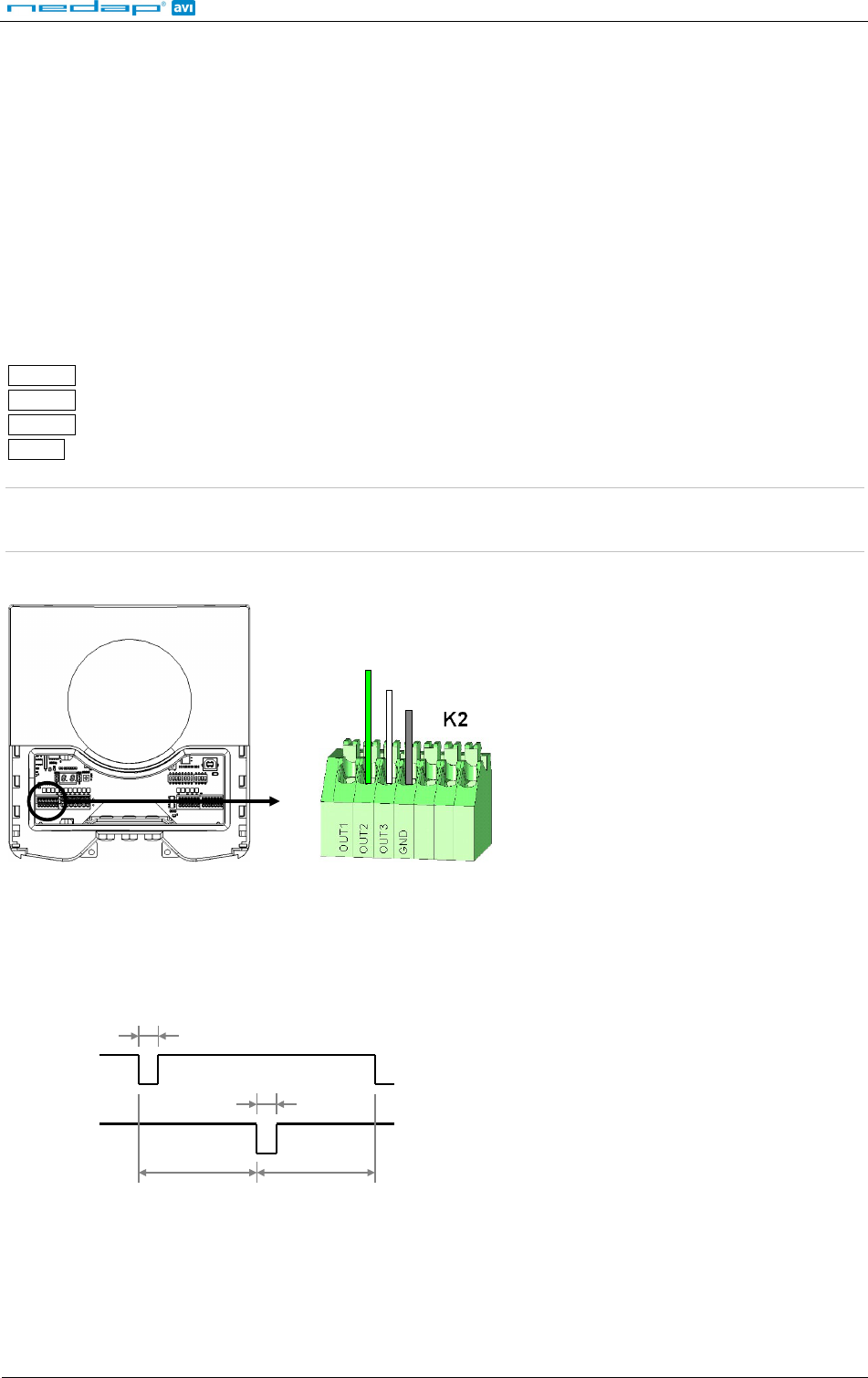
Interface connections:
Wiegand connections Magstripe connections
OUT1
- CLS: Card loaded
OUT2
Data-0 (green) RCP: Clock
OUT3
Data-1 (white) RDP: Data
GND
Ground (black) GND: Ground
Note 1: Maximum cable length 150 meters (500 feet)
Note 2: The wiegand/magstripe interface is not supported by the backward compatible processor !
GND
DATA-1
DATA-0
Figure 10: Wiegand wiring
3.4.2 WIEGAND TIMING
In the figure below the Wiegand protocol timing is specified.
Tpw
5V
0V
DATA-1
5V
0V
DATA-0
Tpi
Tpi
Tpw
Timing constants:
Tpi Pulse interval time 1msec
Tpw Pulse width time 50µsec
Figure 11: Wiegand protocol timing
uPASS Reach
© Nedap AVI Page 13 of 27
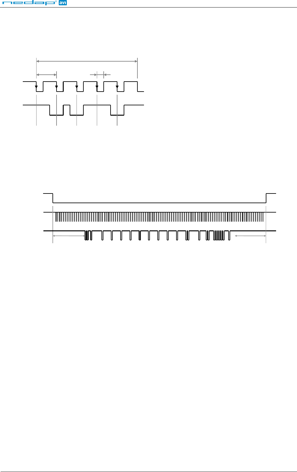
3.4.3 MAGSTRIPE TIMING
In the figure below the timing for one magstripe character is specified. Each bit consists out of one period low
(220µsec) and two periods high (440µsec). The bit times have an accuracy of 10 percent. The data-signal RDP is
valid and stable on the falling edge of the clock-signal RCP.
odd par i t y
ms b
l sb
3300µsec
0
1
1
0
1
220µsec
660µsec
5V
0V
RCP
5V
0V
RDP
Timing constants:
Clock period 660µsec
Clock high 440µsec
Clock low 220µsec
Data preamble 11msec
Data postamble 11msec
Figure 12: Magstripe protocol timing one character
The CLS card loaded signal will be active (=low) during the complete transmission.
Before and after the data 16 clock pulses are generated (postamble and preamble).
The number of data characters is determined by the tag.
Below is an example of a complete magstripe event.
5V
0V
CLS
5V
0V
RDP
5V
0V
RCP
11msec
11msec
Figure 13: Example magstripe event
uPASS Reach
© Nedap AVI Page 14 of 27
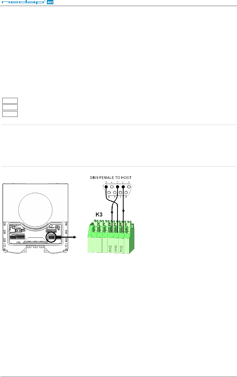
3.4.4 RS232 CONNECTION
The uPASS Reach reader has an on-board RS232 interface for communication with a host system or for
configuring reader settings.
By default the RS232 interface is connected to the UHF processor. This is required when using the UHFtool
software. It is advised to use this tool to configure the reader. Software developers can find the RS232
communication protocol description in the firmware manual.
The RS232 interface can also be connected to the backwards compatible processor. This offers users a
compatible interface with the TRANSIT reader. The communication protocol, baud rate, data format and flow
control depend upon the firmware in the backward compatible processor (e.g. P61 or Q70). See separate
documentation.
Connections:
RXD
Receive data (input)
GND
Ground
TXD
Transmit data (output)
Note 1: The RS232 interface is disabled while the USB interface is in use !!!
Note 2: Enable the on-board RS232 interface by setting DIP-switch SW1-2 to ON. See chapter 4.1 for details.
Note 3: Optionally select the backward compatible processor with DIP-switch SW1-1.
Note 4: Maximum cable length of 15 meters (50 feet) or the cable length equal to a capacitance of 2500pF.
Note 5: The RS232 interface does not support any hardware handshake signals.
Figure 14: RS232 wiring
uPASS Reach
© Nedap AVI Page 15 of 27
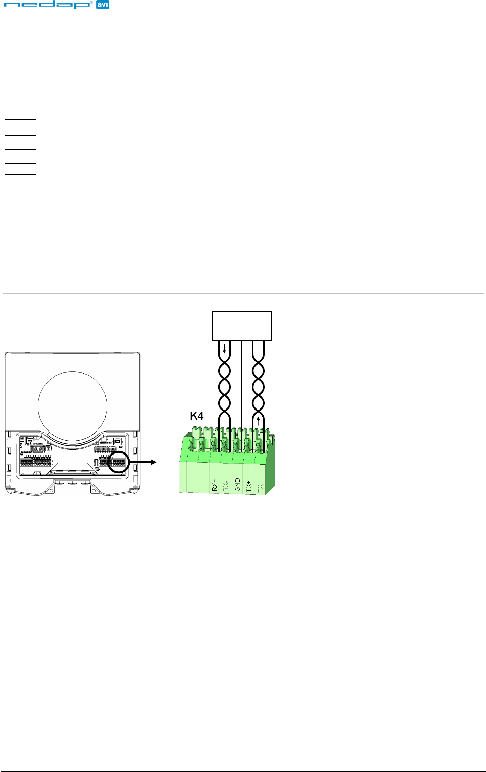
3.4.5 RS422 CONNECTION
The uPASS Reach reader has an on-board RS422 interface. The RS422 interface is similar to the RS232 interface. It
shares the same communication protocol. The RS422 interface is commonly used when longer cable lengths are
required.
Connections:
RX+
Receive line (positive)
RX-
Receive line (negative)
GND
Ground
TX+
Transmission line (positive)
TX-
Transmission line (negative)
RX+ and RX- inputs are terminated with a 120Ω resistor.
TX+ and TX- must be terminated at the host side.
Note 1: The RS422 interface is disabled while the USB interface is in use !!!
Note 2: Enable the on-board RS422 interface by setting DIP-switch SW1-2 to OFF. See chapter 4.1 for details.
Note 3: Optionally select the backward compatible processor with DIP-switch SW1-1.
Note 4: Maximum cable length 1200 meters (4000 feet).
TX-
TX+
GND
RX+
RX-
HOST
Figure 15: RS422 wiring
uPASS Reach
© Nedap AVI Page 16 of 27
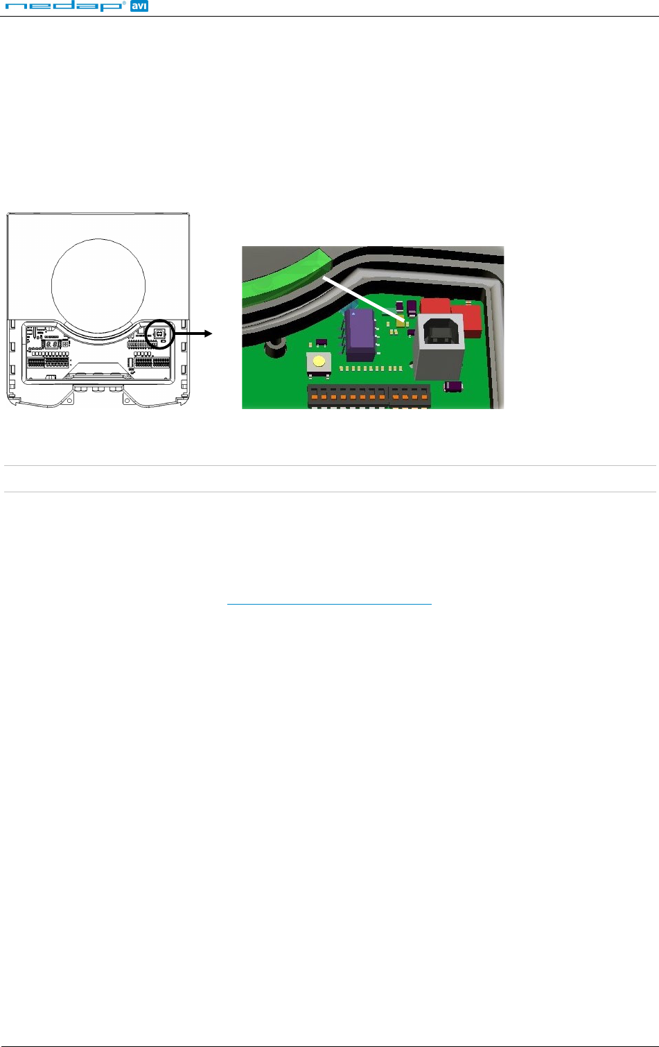
3.4.6 USB CONNECTION
The uPASS Reach reader features an USB interface for service and installation purposes. The USB connector (Type
B) is accessible behind the service cover. The reader will automatically detect when the USB cable is connected.
The USB interface can be used to configure the reader using the UHFtool software (as descibed in chapter 7).
The USB interface can also be used to communicate with the backward compatible processor. For example
upgrade the firmware in the backward compatible processor using the PICload software. Ensure that DIP-switch
SW1-1 is in the correct position.
USB type B
Figure 16: USB interface
Note: While the USB interface is in use, the on-board RS232 and RS422 interfaces are disabled !!!
USB Driver installation
Make sure your computer is connected to the internet. The driver should install automatically via Windows
update when the uPASS Reach reader is connected to your PC via the USB cable. Follow the driver installation
wizard. If you do not see the Windows update pop-up, you can manually install the driver. To manually install,
you need to go to FTDI’s website at www.ftdichip.com/Drivers/VCP.htm and download the VCP (Virtual Com
Port) drivers for your operating system. Drivers for MacOS and Linux are available as well.
uPASS Reach
© Nedap AVI Page 17 of 27
3.5 DIGITAL I/O
3.5.1 RELAY OUTPUT
By default the relay output is automatically activated upon identification of a tag.
When the backward compatible processor is selected, the relay output is controlled by the backward compatible
processor. Please refer to the corresponding firmware manual for details.
The ‘smile’ on the front cover lights-up simultaneously with the relay output.
Connections:
NC
Relay contact normally closed
COM
Relay contact common
NO
Relay contact normally open
Contact ratings:
Max. switching current: 2A
Max. switching voltage: 24VDC
Max. switching power: 50W
CONTACT
SUPPLY
Figure 17: Relay output
uPASS Reach
© Nedap AVI Page 18 of 27
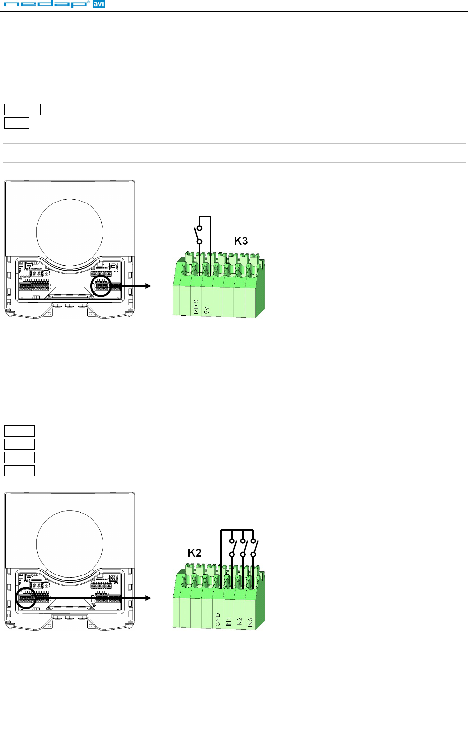
3.5.2 READ DISABLE INPUT
The reading of the uPASS Reach can be completely disabled with the RDIS input. This input is commonly used in
combination with a sensor (e.g. inductive loop) that detects the presence of a person or vehicle. Use always a
relay contact to connect the internal 5V to the RDIS input. When the RDIS input is unused the reader is enabled.
Connections:
RDIS
Read disable input
5V
Internal 5V source for read disable input
Warning: Using an external 5V supply can damage the unit.
Read disable
input
Figure 18: Read disable input
3.5.3 GENERAL PURPOSE INPUTS
Three general purpose inputs are available on the uPASS Reach reader. They have the function as described in
the firmware manual.
Connections:
IN1
General purpose input 1 (active low)
IN2
General purpose input 2 (active low)
IN3
General purpose input 3 (active low)
GND
Ground
General purpose inputs
Figure 19: GPIO inputs
uPASS Reach
© Nedap AVI Page 19 of 27
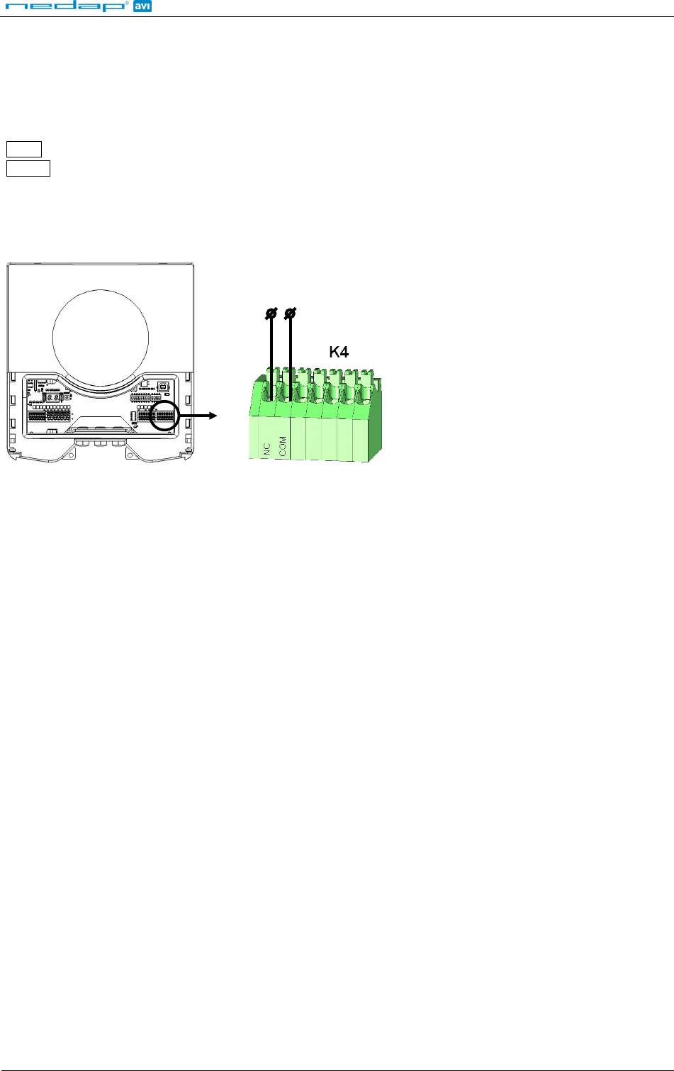
3.5.4 TAMPER SWITCH
An internal magnet provides tamper indication when the service cover is opened. This contact may be
connected to an external alarm system. The contacts are normally closed when the cover is in place.
Tamper switches of multiple readers can be connected in series.
Connections:
NC
Tamper switch (normally closed)
COM
Tamper switch (common)
Contact ratings:
Max. current 50 mA (0.5 Volt voltage drop)
Max. switching voltage +24 VDC
Tamper switch
Figure 20: Tamper switch
uPASS Reach
© Nedap AVI Page 20 of 27
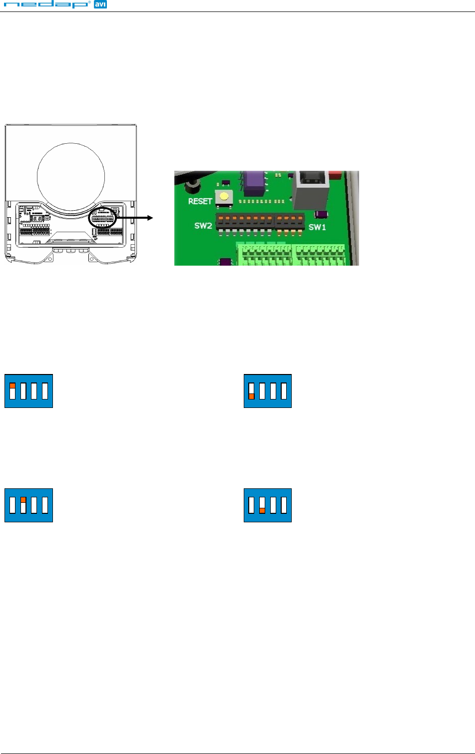
4 DIP-SWITCH SETTINGS
The DIP-switches are located behind the service cover.
Switches SW1-1 through SW1-4 are described below.
The switches SW2-1 through SW2-8 are reserved for the backward compatible processor (e.g. P61 or Q70). Please
refer to the firmware manual for details.
1 2 3 4 5 6 7 8 1 2
3 4
Figure 21: DIP-switches
4.1 COMPATIBILITY MODE
Compatibility mode selection. Enable UHF processor or backward compatible processor (e.g. P61 or Q70).
This selection determines the communication protocol on the USB and RS232/RS422 interfaces. It also
determines the relay output control.
When using wiegand or magstripe communinication the setting of this switch has no effect.
ON
1
2
3
4
SW1
UHF processor
ON
1
2
3
4
SW1
Backward compatible processor (e.g. P61 or Q70)
4.2 RS232 / RS422 SELECTION
On-board RS232 or RS422 interface selection.
ON
1
2
3
4
SW1
On-board RS232 interface enabled
ON
1
2
3
4
SW1
On-board RS422 interface enabled
4.3 UNUSED SWITCHES
The switches SW1-3 and SW1-4 are reserved for future use. It is recommended to leave these switches in the ON
position.
uPASS Reach
© Nedap AVI Page 21 of 27
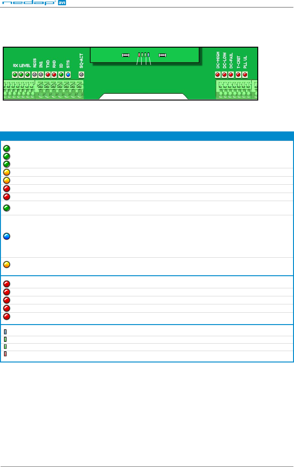
5 LED INDICATIONS
A number of LED’s indicate the current status of the uPASS Reach reader.
UERR
UREAD
UTAG
USTS
E R N I
RESET
TEST
Figure 22:
LED locations
Table 1 below describes the function of each LED.
LED Description
RX LEVEL
LED bar indicating the received tag signal strength. This LED bar may also indicate the
presence of radio interference. In case of interference, try switching to a different frequency.
See chapter 6.
RDIS Read Disable LED. On while reading disabled. See chapter 3.5.2.
IN1 Input 1 status. On when input 1 contact is closed. See chapter 3.5.3.
TXD Transmit serial data (backward compatible processor).
RXD Receive serial data (backward compatible processor).
ID Identification. Blinks fast when a valid transponder is identified (backward compatible
processor).
STS
Status LED (only backward compatible processor).
Slow blinking: System’s heartbeat (0.8 sec on / 0.8 sec off). Indicates that the power is on
and the processor is running.
Fast blinking: Bootloader says hello. Indicated after a restart.
Twice blinking: Configuration menu active.
Off: Abnormal situation.
SQ-ACT Squelch active. When squelch is enabled and the transponder return signal below threshold
level.
DC-HI Power supply voltage too high. See chapter 3.3.
DC-LO Power supply voltage too low. See chapter 3.3.
DC-FAIL Internal supply voltage failure. See chapter 3.3.
T-CRIT Temperature critically high.
PLL UL PLL unlocked. Error indication only. No direct hardware action implemented.
USTS UHF processor status LED. Should be slowly blinking.
UTAG Tag found. RN16 received.
UREAD Tag data read complete.
UERR Error during tag identification.
Table 1: LED indicators
uPASS Reach
© Nedap AVI Page 22 of 27
6 UHF FREQUENCIES
6.1 RADIO REGULATIONS
The uPASS Reach reader operates on the 860 – 960 MHz band. Regulations in this band are not standardized
world-wide. Generally the regulations can be divided into several regions.
Per region a specific frequency band is available. This frequency band is divided into frequency channels. If local
radio regulations require frequency hopping (FHSS), then the uPASS Reach automatically selects and uses the
available channels.
Region Technique Frequency Channels
Europe 865.6 - 867.6 MHz 4
Americas FHSS 902.0 - 928.0 MHz 52
Brazil FHSS 915.0 - 928.0 MHz 43
China FHSS 920.5 - 924.5 MHz 20
Australia FHSS 920.0 - 926.0 MHz 12
Israel 915.0 - 917.0 MHz 4
Japan LBT 952.0 - 954.0 MHz -
Korea FHSS 917.0 - 920.8 MHz -
Table 2: Region specific parameters
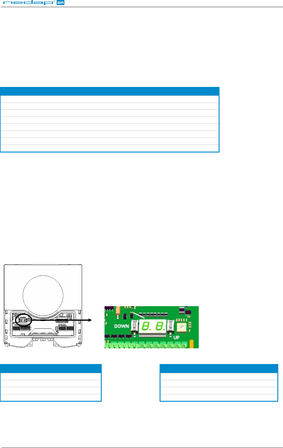
6.2 FREQUENCY CHANNEL SELECTION
If no frequency hopping is required, you should select an available frequency channel manually. This can be
realized as described below. Select an available frequency channel to achieve the best performance and to avoid
interference from other readers or equipment.
Press the UP or DOWN switch once and the display will show a value indicating the currently selected frequency.
Lookup the display value in the table below to find out what the actual operating frequency is.
When the display is on, press the UP switch to select a higher frequency. Similarly, press the DOWN switch to
select a lower frequency.
Alternatively the UHFtool software can be used to setup the frequency channel selection. See also chapter 7.
DISPLAY
Figure 23: frequency channel setting
Display value Frequency Display value Frequency
1 865.7 MHz 1 915.1 MHz
2 866.3 MHz 2 915.7 MHz
3 866.9 MHz 3 916.3 MHz
4 867.5 MHz 4 916.9 MHz
Table 3: Frequency values for Europe Table 4: Frequency values for Israel
uPASS Reach
© Nedap AVI Page 23 of 27
7 READER CONFIGURATION
The uPASS Reach reader settings can be configured easily using the UHFtool software. Software developers can
find the communication protocol description in the firmware manual.
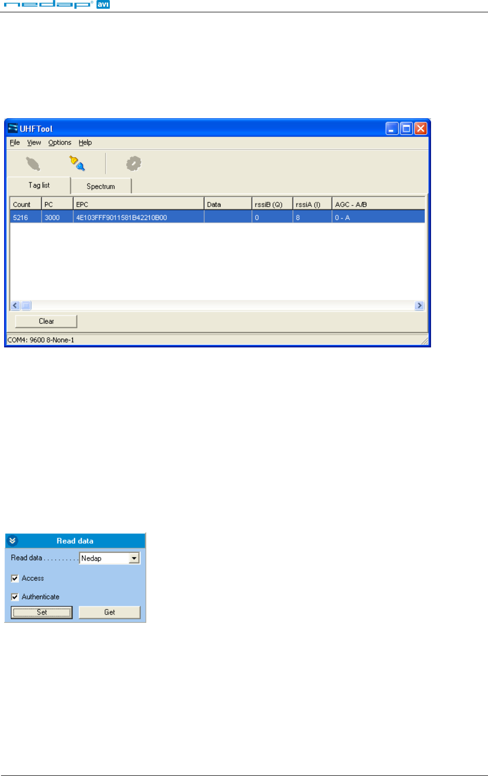
7.1 UHFTOOL SOFTWARE
Figure 24: UHFtool software
7.2 SETTINGS
Click 'View', 'Show config sidebar' or press F11 to show the configuration sidebar. In the sidebar the
configuration categories are shown. Expand or collaps the setting panels by clicking on it.
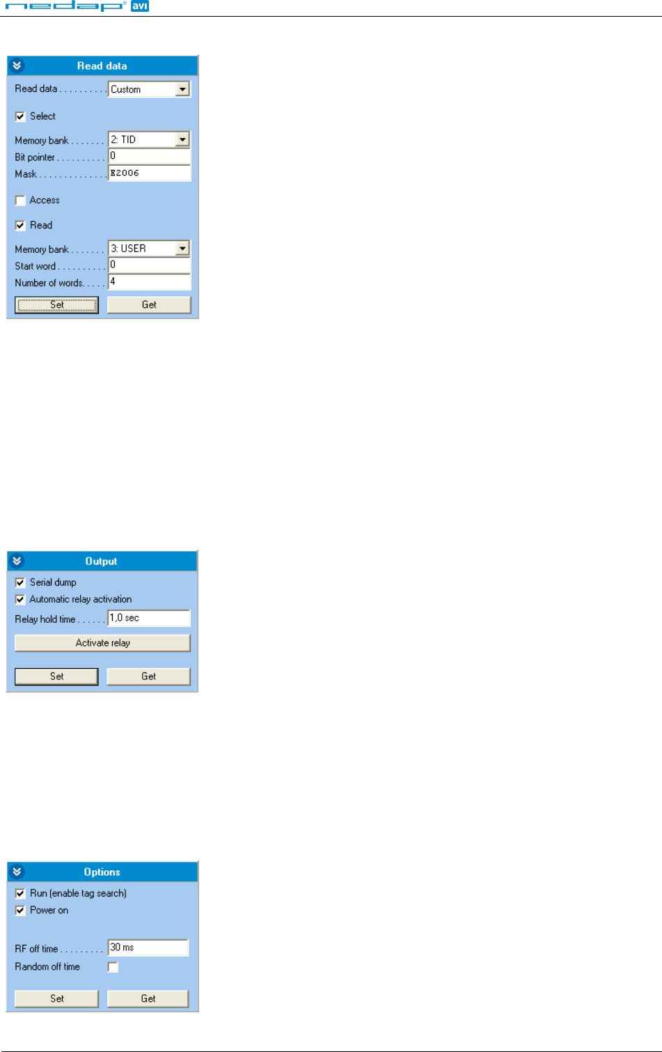
7.2.1 READ DATA
Configure here which tags should be selected, how to access these tags, what data should be read from these
tags and if a security check should be performed.
By default the reader is configured to select any tag and read its EPC number.
Read only NEDAP UHF tags and use two way authentication:
Figure 25: Read data example 1
uPASS Reach
© Nedap AVI Page 24 of 27
Read only NXP UCODE tags (TID starts with E2006) and read 4 words from user memory.
Figure 26: Read data example 2
7.2.2 OUTPUT
Configure UHF processor outputs.
Enable 'Serial dump' to enable the serial output upon identification. Only disable 'Serial dump' to optimize the
identification speed when using the wiegand or magstripe interface or the backwards compatible processor.
Enable 'Automatic relay activation' to activate the relay upon identification. When disabled the relay can only be
activated manually.
The 'Relay hold time' setting is the minimum time the relay is activated.
Figure 27: Output settings
7.2.3 OPTIONS
Configure RF options.
Here the tag searching and RF output power can be enabled/disabled.
For systems that do not use frequency hopping (e.g. in europe) the RF off time parameter can be used to enable
time sharing between multiple readers on the same frequency.
Figure 28: RF Options

uPASS Reach
© Nedap AVI Page 25 of 27
7.3 EXPERT SETTINGS
Click 'Options', 'Usermode', 'Expert' to show additional configuration settings for advanced users.
7.3.1 FREQUENCY
Here you select the operating frequency. Only for systems that do not use frequency hopping (e.g. in europe).
7.3.2 SQUELCH
Enable the squelch to reduce the read range. This is useful to optimize lane separation.
When the squelch is enabled, you can set the squelch level. This level ensures that only tags with a returned
signal strength higher then the squelch level are identified.
When the squelch is enabled and the returned signal strength is lower then the squelch level, the SQ-ACT LED
indicates that the tag is rejected. See also chapter 5.

uPASS Reach
© Nedap AVI Page 26 of 27
A TECHNICAL SPECIFICATIONS
ITEM SPECIFICATION REMARK
Dimensions 200x220x46.5mm (7.87 x 8.66 x 1.83 inch)
Weight 0.75 kg (1.65 lbs)
Enclosure color RAL7016 (light gray)
Enclosure material Polycarbonate
Chassis material Aluminum
Cable entry fittings AGRO Progress MS EMC IP68 4-6mm cable diameter
Recommended wire
stripping length 8 … 10mm (0.3 … 0.4 inch)
L
Connector K5 0.5mm2 … 1.5mm2Springcage type PTSA 1.5 (AWG20 … 16)
Connector K2,3,4 0.14mm2 … 0.5mm2Springcage type PTSA 0.5 (AWG24 … 20)
Protection class IP65
Operational
temperature -30 °C … + 60 °C
Relative humidity 10 .. 93 % non condensing
Identification range Up to 4 meters (12 feet) With passive NEDAP UHF tags
Power supply 12 … 24VDC ±10% linear power supply
Current consumption 1.0A @ 12VDC, 0.5A @ 24VDC
Operating frequency
Europe: 865 … 868 MHz
Americas: 902 … 928 MHz (FHSS)
Brasil: 915 … 928 MHz (FHSS)
China: 920 … 928 MHz (FHSS)
Australia: 920 … 926 MHz (FHSS)
Japan: 952 … 954 MHz
Polarisation Horizontal
ERP / EIRP < 2 W (33 dBm) ERP (CE)
< 4 W (36 dBm) EIRP (FCC)
Immunity EN 301 489 part 1&3 v1.4.1
Safety EN 60950-1:2006
Emission
EN 302 208-2 v1.3.1
FCC part 15.247 incl. Spread Spectrum
Industry Canada RSS210
Shock IEC 68-2-27 Ea 50 G, 6 ms, 10x3 dir
Bump IEC 68-2-29 Eb 25 G, 6ms, 1000x3 dir
Random vibration EN 50155 5 – 150Hz, 5 G, 20 sweeps x 3 dir
uPASS Reach
© Nedap AVI Page 27 of 27
B PART NUMBERS
READERS
NEDAP uPASS Reach (EUR)
NEDAP uPASS Reach (USA)
NEDAP uPASS Reach (JPN)
part number: 9942319
part number: 9945466
part number: 9945474
ACCESSORIES
Adjustable mounting bracket part number: 9875840
Weather protection hood part number: 7591152
Pole mounting kit (includes 7591152) part number: 9943803
TRANSPONDERS
UHF Windshield Tag part number: 9942327
UHF Windshield Tag Tamperproof part number: 9442335
Combi card UHF + Mifare part number: 9442343
Combi card UHF + Nedap part number: 9442351
Combi card UHF + EM part number: 9442360