Nedap N V VP1103 Inductive Card Reader User Manual
N. V. Nederlandsche Apparatenfabriek NEDAP Inductive Card Reader
User Manual
Panel Reader
VP1103
Manual article number 5277078 October 2010 / Manual version 1.1
Service manual
For installation, operation and service
VP1103-200PM-00GB-Panel reader Manual version 1.1
Preface
This manual describes the installation, operation, troubleshooting and maintenance of the Panel
reader. Read this manual entirely and when installing, carefully follow the instructions step by
step as described in the manual.
Pictograms
Please pay extra attention here. This pictogram indicates an important subject.
Version overview
Manual version 1.0 / May 2010 First release.
Manual version 1.1 / October 2010 Wiring adjustment.
This information is furnished for guidance, and with no guarantee as to its accuracy or completeness; its publication conveys no
license under any patent or other right, nor does the publisher assume liability for any consequence of its use; specifications and
availability of goods mentioned in it are subject to change without notice; it is not to be reproduced in any way, in whole or in part,
without the written consent of the publisher.
© Nedap N.V., AGRI P.O. Box 104 NL-7140 AC GROENLO The Netherlands
Model: VP1103
IC: 1444A-VP1103 and FCC ID: CGDVP1103
Compliance statements
This device complies with part 15 of the FCC Rules and to RSS210 of Industry Canada.
Operation is subject to the following two conditions:
(1) this device may not cause harmful interference, and
(2) this device must accept any interference received, including interference that may cause undesired
operation.
Cet appareil se conforme aux normes RSS210 exemptés de license du Industry Canada. L'opération est soumis
aux deux conditions suivantes:
(1) cet appareil ne doit causer aucune interférence, et
(2) cet appareil doit accepter n'importe quelle interférence, y inclus interférence qui peut causer une opération
non pas voulu de cet appareil.
Warning (part15.21)
Changes or modifications not expressly approved by party responsible for compliance could void the user’s
authority to operate the equipment.
This in particular is applicable for the antenna which can be delivered with the System.

VP1103-200PM-00GB-Panel reader Manual version 1.1
Table of contents
Preface and Version overview
Table of contents
1. Introduction .........................................................................................................................1
1.1. Description ............................................................................................................................1
1.2. Functioning............................................................................................................................2
2. Installing the VP1103 Panel reader ...................................................................................3
2.1. Mounting the VP1103 Panel reader......................................................................................3
2.2. Connecting to a PC or a weight scale via RS232.................................................................4
2.2.1. Connecting RS232 via a Sub-D connector..............................................................4
2.2.2. Connecting RS232 via a Velos Panel reader cable.................................................4
2.3. Connecting to a Velos VPU via CAN communication...........................................................5
2.3.1. Connecting one VP1103 Panel reader ....................................................................5
2.3.2. Connecting several VP1103 Panel readers to a Velos VPU ...................................6
3. Starting up operation..........................................................................................................7
3.1. Turn on the power.................................................................................................................7
3.2. Checking the VP1103 Panel reader .....................................................................................7
3.2.1. Checking the CAN communication with an VPU .....................................................7
3.2.2. Checking the RS232 connection to a PC ................................................................7
4. Maintenance, malfunction and disposal...........................................................................8
4.1. Maintenance..........................................................................................................................8
4.2. Malfunction............................................................................................................................8
4.3. Disposal ................................................................................................................................8
Appendix A Technical specifications....................................................................................9
Appendix B Corridor requirements.....................................................................................10
VP1103-200PM-00GB-Panel reader Manual version 1.1 / Page 1
1. Introduction
The VP1103 Panel reader identifies RFID ear tags attached to individual animals. The
identification can be used for registration of the animals that have passed the Panel reader unit
(VP1103). A weight scale can optionally be connected to the Panel reader.
This device complies with Part 15 of the FCC Rules and to RSS-210 of Industry Canada.
Operation is subject to the following two conditions: (1) this device may not cause
harmful interference, and (2) this device must accept any interference received, including
interference that may cause undesired operation.
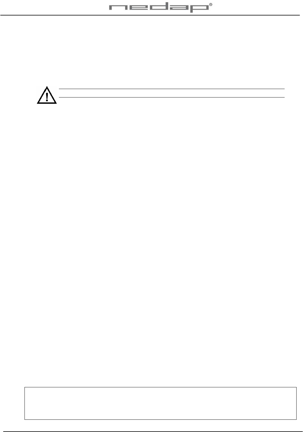
1.1. Description
The VP1103 Panel reader system consists of a Panel reader unit that is connected to a VPU
using CAN communication or a connection to a PC or a weight scale through RS232.
1. Panel reader unit
VP1103
2. Power supply VP2001
and VPU VP8001
3. Optional PC
4. Optional Weight scale
5. Optional Router and
switch
6. Internet
7. RS232 connection
8. CAN communication
9. LAN connection via
UTP cat5 cable
Figure 1. Overview VP1103 Panel reader system
9
8
7
3
1
Weight
scale 4
OR
1
56
3
3
OR
2
VPU
VP2001
OR
VP1103-200PM-00GB-Panel reader Manual version 1.1 / Page 2
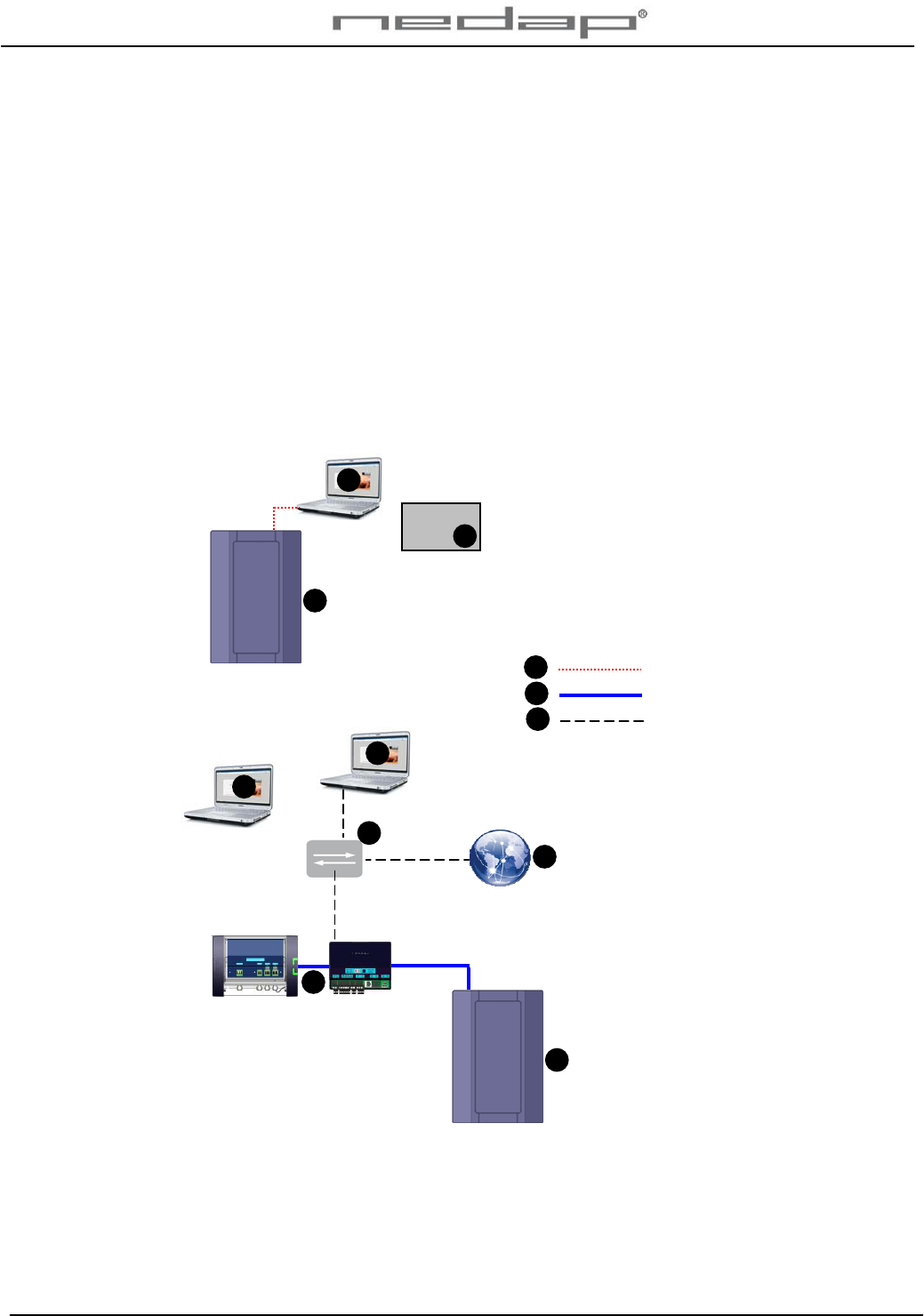
1.2. Functioning
The VP1103 Panel reader creates a magnetic field around the antenna that is used to identify
the tags on ISO frequency 134.2 kHz. The Panel reader is connected to a VPU using CAN
communication or to a PC or a weight scale through RS232.
The Panel reader identifies animals that pass the Panel reader unit. When an animal is
identified by the Panel reader, the tag number will be dumped.
1. VP1103 Panel reader
unit
2. Responder number
(animal identification)
3. Tag number dump
Figure 2. Connection between the Panel reader and the dumped tag numbers
The tag numbers are stored via CAN communication in the VPU or dumped according to the
ISO protocol 11784/11785 via an RS232 connection in e.g. the Windows Hyper Terminal
communication program.
3
2
1
VP1103-200PM-00GB-Panel reader Manual version 1.1 / Page 3
2. Installing the VP1103 Panel reader
2.1. Mounting the VP1103 Panel reader
Installation and service should be done only by trained personnel. Always turn off the main
power when working on the de electrical installation. Keep animals away from the antenna
during installation and service. Close all covers when ready with installation or service.
See Appendix A for technical specifications before mounting. See Appendix B for corridor
requirements.
Mount the Panel reader unit firmly on a wall or at a (non metal) frame.
Mounting requirements:
1. The Panel reader must not be mounted close to any iron. This will influence the
performance of the antenna.
2. The Panel reader must not be mounted close to electrical equipment with
background noise. This can disturb the antenna.
3. The Panel reader must be mounted on a wall close to a stable power supply.
4. The Panel reader must be mounted > 1.5 m. from electrical cables or power supply.
5. The Panel reader may not be exposed to direct sunlight.
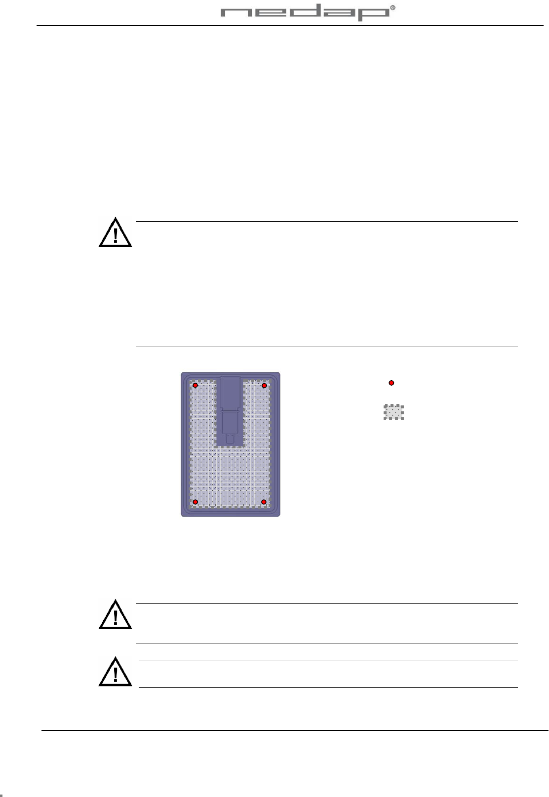
Example mounting
positions
Drill zone at least 4 cm
from the sides
Figure 3. Mounting positions on rear view VP1103 Panel reader
Mount the Panel reader in 4 positions with screws, bolts, and plugs etc. suitable to support the
Panel reader. Use a large washer behind the bolt/screw to give extra support. Use a screw or
washer with a minimum head diameter of 18 mm. The size of the holes in the antenna must be
corresponding with the size of the bolts or screws that are used.
Don’t damage the antenna when drilling holes for mounting the Panel reader. This
could damage the electronics and affect the functioning of the Panel reader. Keep a
minimum drill distance of 4 cm from the sides.
Install cables and power supplies / transformers > 1.5 m. from the Panel reader if
possible.
VP1103-200PM-00GB-Panel reader Manual version 1.1 / Page 4
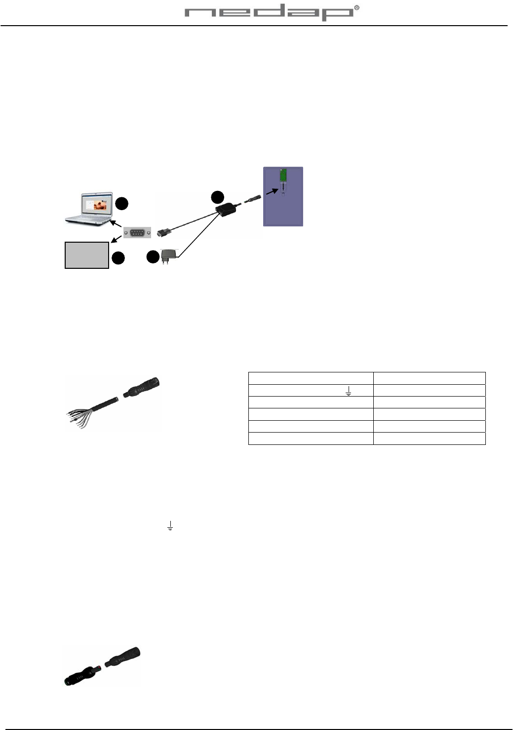
2.2. Connecting to a PC or a weight scale via RS232
2.2.1. Connecting RS232 via a Sub-D connector
Connect a PC or a weight scale to the VP1103 Panel reader RS232 Sub-D connection from the
connector. Use an extension cable (art. nr 7707037) of 4 meters to extend the cable if
necessary.
OR
1. RS232 connection to
PC
2. RS232 connection to
weight scale or other
device
3. Connector
4. Adaptor
Figure 4. VP1103 Panel reader RS232 connection
2.2.2. Connecting RS232 via a Velos Panel reader cable
Connect a PC or a weight scale or other device to the Panel reader via a Velos Panel reader
cable (art.nr.7707029). This cable can also be used for connection to a VPU. Shortening of the
Velos Panel reader cable is allowed.
Use an extension cable (art. nr 7707037) of 4 meters to extend the Velos Panel reader cable if
necessary.
VP1103 PC or Weight scale
Shield -
Black - -
Red + 12-27 V DC
Green (TxD) RxD
Green / White (RxD) TxD
Velos Panel reader cable
Red + Input voltage 12-27 V DC
Black - Minus
Blue CH Not connected
Blue / White CL Not connected
Shield Shielding connected to minus
Orange ~ Synchronization (antenna) HDX
Orange / White ~ Synchronization (antenna) HDX
Green TxD TxD RS232 Communication, normally connected to RxD from PC
Green / White RxD RxD RS232 Communication, normally connected to TxD from PC
Also connect the minus to PC when using RS232 communication
1
2
Weight
scale
3
4

VP1103-200PM-00GB-Panel reader Manual version 1.1 / Page 5
2.3. Connecting to a Velos VPU via CAN communication
2.3.1. Connecting one VP1103 Panel reader
Connect the Panel reader cable (art.nr.7707029) to the VPU connectors.
Shortening of the Velos Panel reader cable (art.nr.7707029) is allowed. Use an extension cable
(art. nr 7707037) of 4 meters to extend the cable if necessary.
VPU VP1103
Orange / White ~
Orange /White
Orange ~
Orange
Shield Shield
Blue / White CL
Blue / White
Blue CH
Blue
Black -
Black
Red +
Red
Not connected Green
Not connected Green / White
VP8001
V
PU
Power supply
(VP2001)
LAN to PC
VP1103-200PM-00GB-Panel reader Manual version 1.1 / Page 6
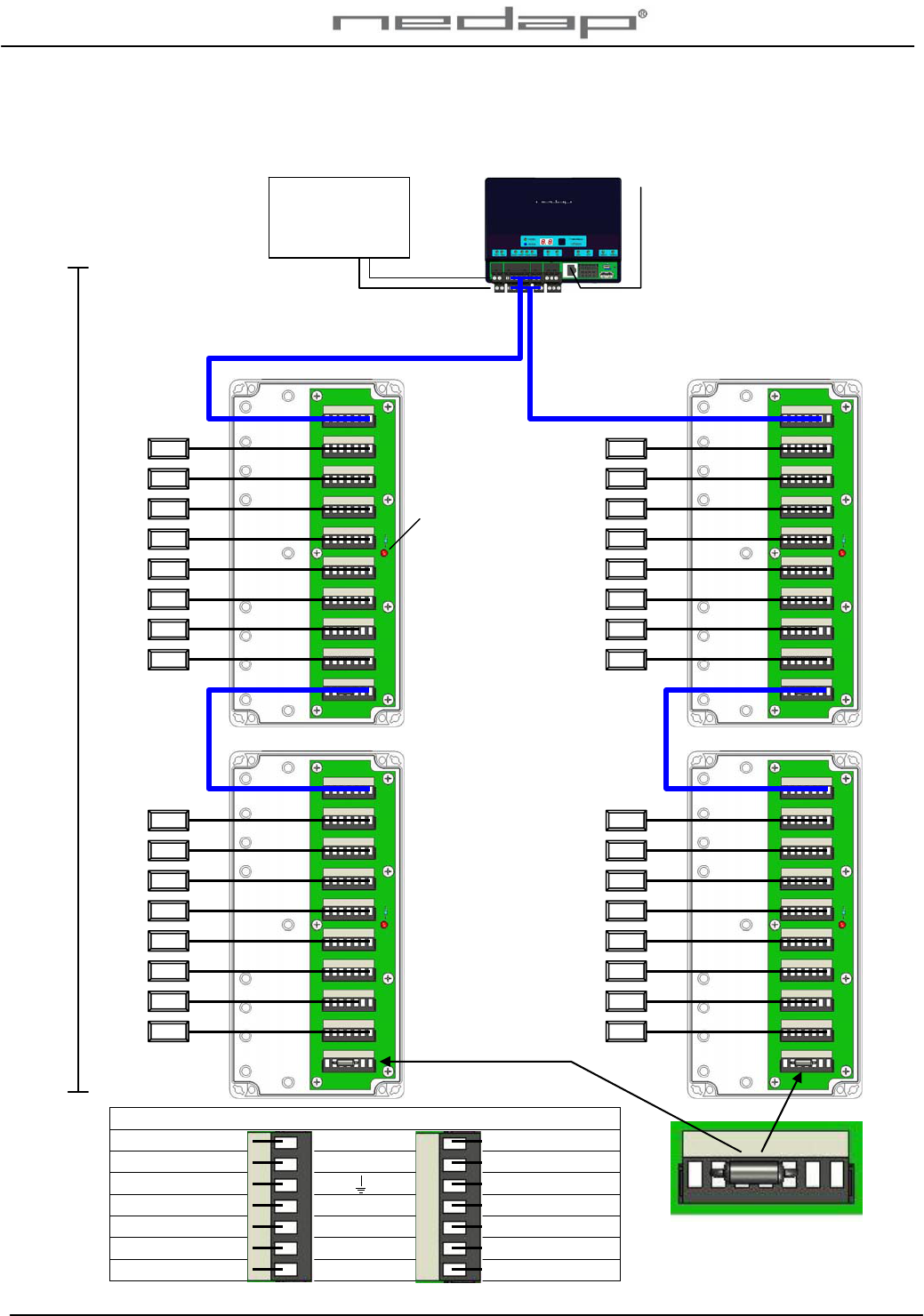
2.3.2. Connecting several VP1103 Panel readers to a Velos VPU
Connect the Panel readers VP1103 to the Velos connection boxes.
VP1103
VP1103
VP1103
VP1103
VP8001
V
PU
Max 80m
From VPU to last VP1103
Velos cable
p
art no. 7705310
End resistor
Only used at last box
Velos cable
Velos cable
Velos cable
Power
indicator
Velos cable VP1103
Orange/white ~
Orange/white
Orange ~
Orange
Shield Shield
Blue/white C
L
Blue/white
Blue C
H
Blue
Black -
Black
Red +
Red
Power supply
(VP2001)
Max = 2x4A
LAN to PC
Keep a distance of
more than 2 meter
between the VP1103
Panel readers to
p
revent interference
VP1103-200PM-00GB-Panel reader Manual version 1.1 / Page 7
3. Starting up operation
The Panel reader is pre-tuned and ready for use.
3.1. Turn on the power
For an RS232 connection: Put the adaptor into an electric socket.
For CAN communication to a VPU: Turn on the Power supply VP2001.
3.2. Checking the VP1103 Panel reader
3.2.1. Checking the CAN connection to the VPU
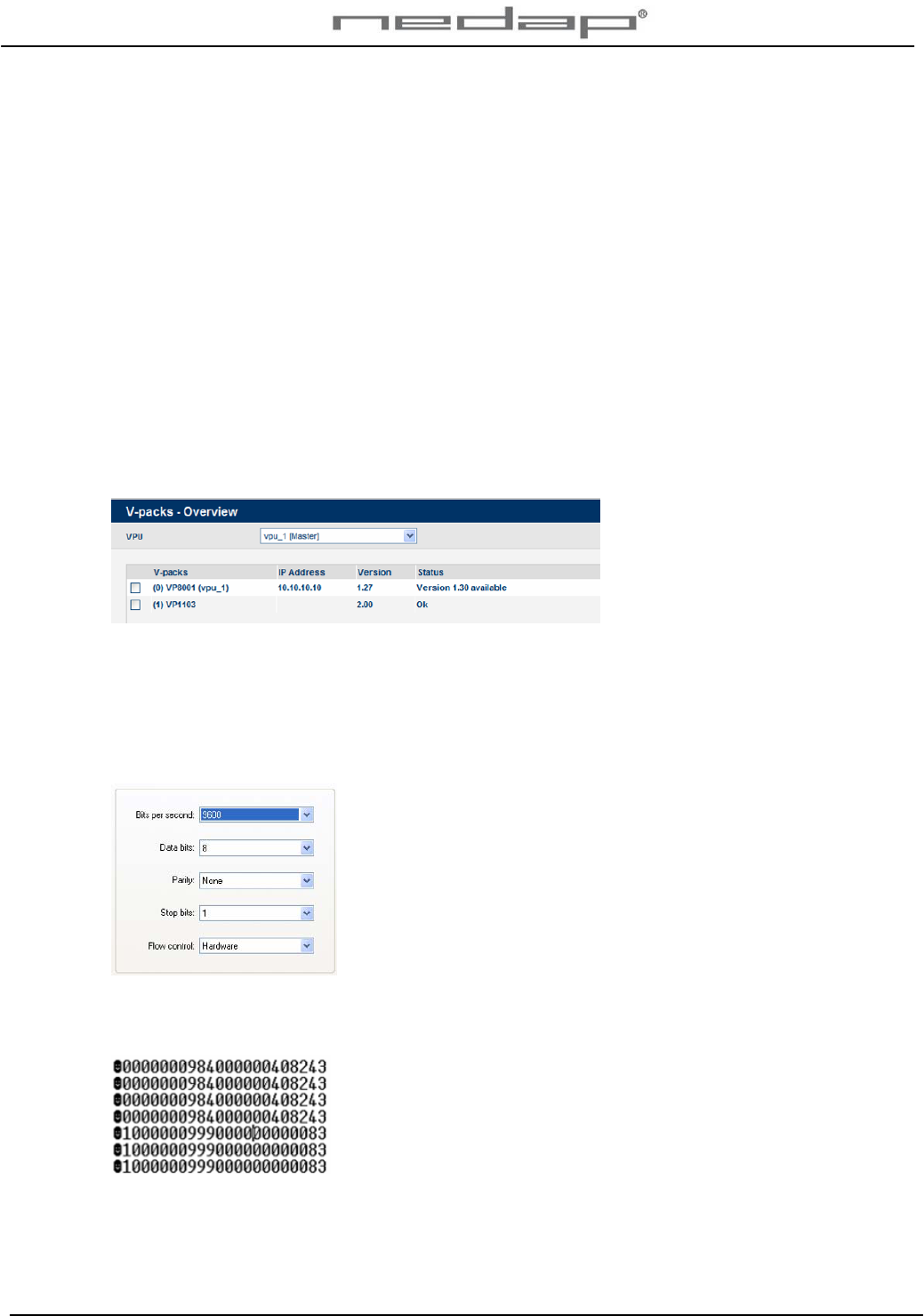
Check the status of the Panel reader that is connected to a VPU in the Velos VPU program web
page Maintenance > V-packs – Overview.
3.2.2. Checking the RS232 connection to a PC
Check the operation of the VP1103 Panel reader that is connected to a PC with the Hyper
Terminal program. Set the baud rate of the Hyper Terminal communication program to 9600.
The other settings are default.
The tags numbers that are identified by the Panel reader will be displayed in the screen
according to the ISO protocol 11784/11785.

VP1103-200PM-00GB-Panel reader Manual version 1.1 / Page 8
4. Maintenance, malfunction and disposal
4.1. Maintenance
Check the operation of the Panel reader regularly.
No regular maintenance is required.
The Panel reader can be cleaned with water and sponge. Avoid (aggressive) cleaning liquids.
4.2. Malfunction
If the Panel reader VP1103 is connected to a VPU, view the actual state of the Panel reader in
the webpage Maintenance > V-packs – Overview.
A reduced antenna performance may be caused by a strong electrical background noise. Install
cables and power supply / transformers > 1.5 m. from the Panel reader.
4.3. Disposal
At discard dispose of materials from the Panel reader in accordance with the current
environmental rules of the state or local governing authorities.
VP1103-200PM-00GB-Panel reader Manual version 1.1 / Page 9
Appendix A Technical specifications
Measurements VP1103 Panel reader
Total height 595 mm
Total width 495 mm
Depth 30 mm
Specifications for transport / installation
Weight VP1103 Panel reader 6.2 kg
Electrical supply
Main supply 100V - 240V
Frequency 50 – 60 Hz
Input voltage (always use Nedap power supply) 12 - 27 V DC
Input current (mA) depends on input voltage 0.75 – 0.5 A
Environmental
Operating temperatures - 10°C / + 50°C
Transport / storage temperatures - 25°C / + 70°C
Relative humidity (non condensing) 10°C / 90%
Enclosure protection class (when cover and cables installed correctly) IP67
The Panel reader may not be exposed to direct sunlight.
The Panel reader must always be transported and stored dry and frost-free.
Other specifications
CAN CAN-bus communication 125 kBit
Power Power consumption 225 mA with antenna switched on (i.c.o. 500 V)
Protected against reverse connection power supply
Software Downloadable by the CAN network
Antennas Internal fixed antenna
Detection distance Depending on used tags
Synchronization Synchronization according to ISO 11785, ISO 24631-7
VP1103-200PM-00GB-Panel reader Manual version 1.1 / Page 10
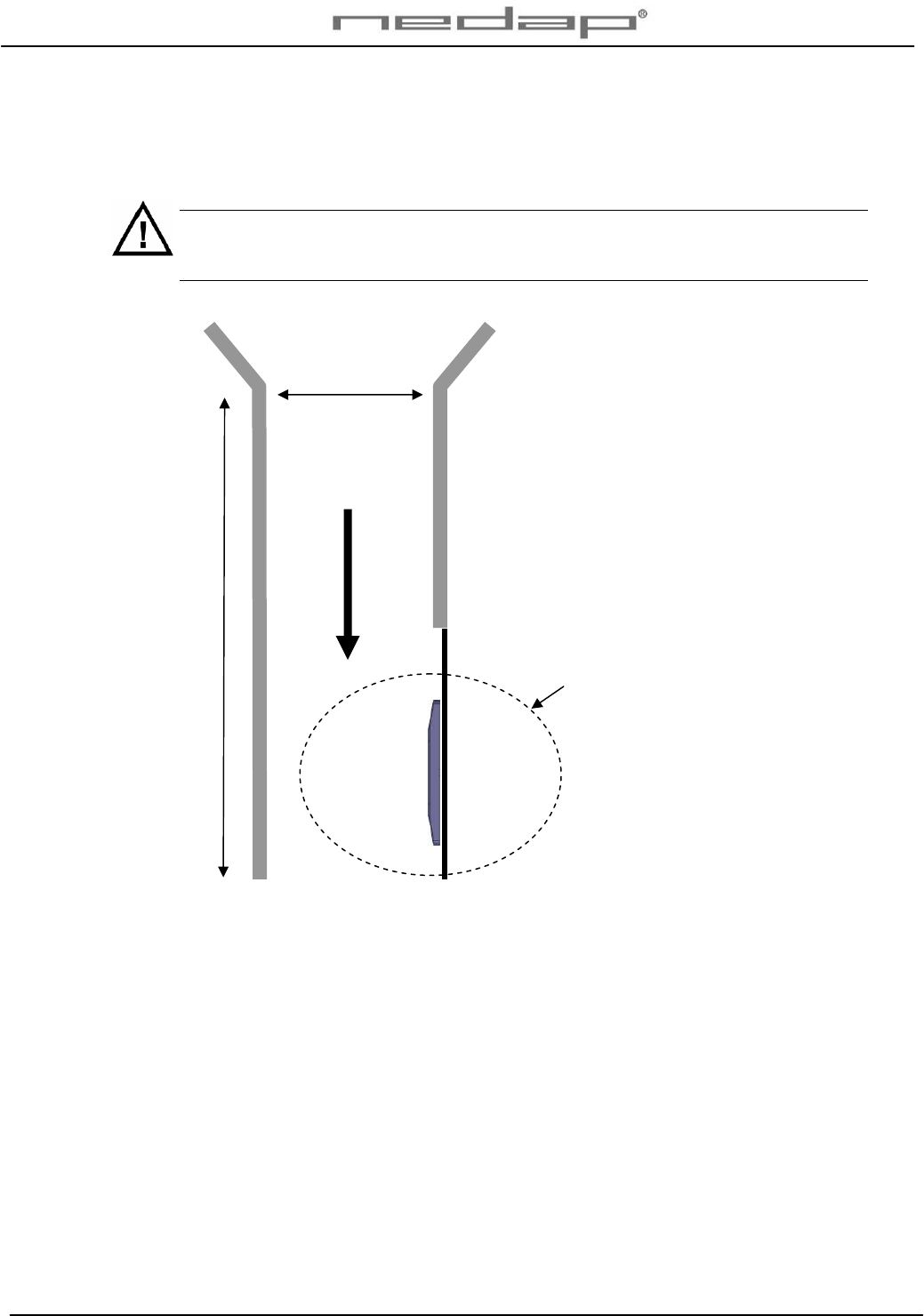
Appendix B Corridor requirements
The maximum corridor width at the Panel reader location will be different for each animal sort
and breed. Make sure the corridor is not too wide at the Panel reader location.
The maximum width of the corridor is essential to achieve a proper working system.
Animals should never be able to pass each other, turn around or walk in the wrong
direction.
IN
The identification distance of the
antenna field
Maximum corridor entrance width:
Allow passage of 1 animal at the
time. Keep the corridor as narrow
as possible.
RFID Eartags : Attach all ear tags
on same side of animals (left in
this example).
The antenna must be mounted at
the side where the tag is
attached.
The identification distance of the
antenna varies per installation. It
depends on the iron and the
background noise in the ISO-
reader area.
Maximum width
1 animal wide
Minimum length 1 animal long