Nedap N V X2 Anti-Pilferage Device User Manual 20120203 Manual X2 V2 0
N. V. Nederlandsche Apparatenfabriek NEDAP Anti-Pilferage Device 20120203 Manual X2 V2 0
UserManual.wiki
>
Nedap N V
>
X2 User Manual
>
User Manual 01
Contents
1.
User Manual 01
2.
User Manual 02
3.
User Manual 03
User Manual 01
Navigation menu
Upload a User Manual
Namespaces
Wiki Guide
HTML
PDF
Info
Views
User Manual
Discussion / Help
Navigation
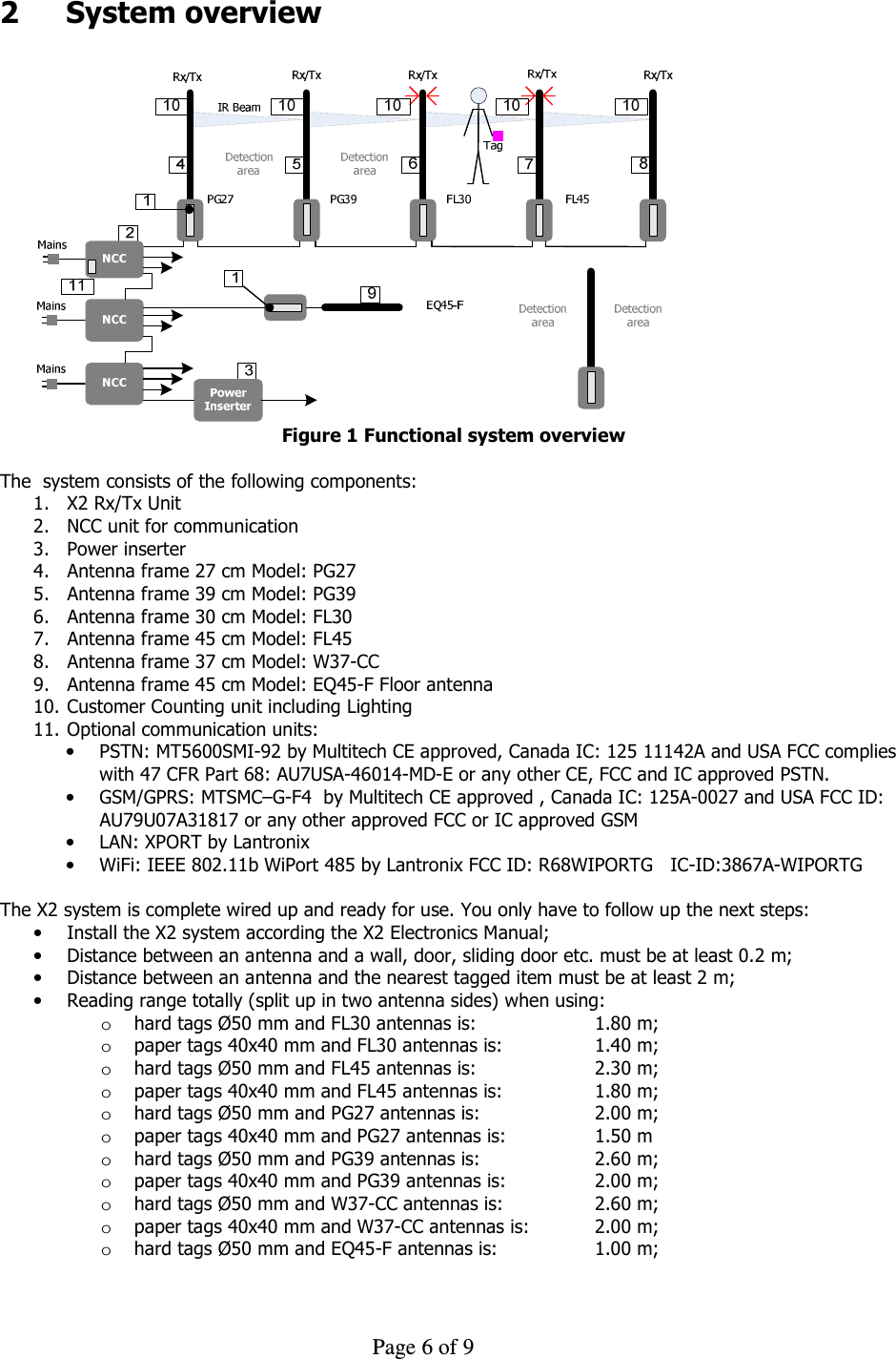
![Page 7 of 9 o paper tags 40x40 mm and EQ45-F antennas is: 0.75 m; • Power up the X2 system • Check the functionality; • Call Nedap Customer Support for quick hands-on problem solution in case of unforeseen problems [see Technical Support]; 3 Wiring diagram Schematically diagrams below shows an example of the connections between used modules. The picture shows the full configuration that can be built up. Ant.Ant.Ant.Ant.Ant.Ant. Figure 2 Example full configuration The connections for a full configuration are: 1. Datacom cable for NCC to Unit X2 Connects Data communication and power from NCC [9203508] to a Unit X2 RX/TX [9938176] 2. Datacom cable between Unit X2 to second Unit X2 Connects the data and power between the X2 RX/TX Units. 3. Coax cable Connects the antenna Match PCBA to X2 RX/TX unit [9938176] for the EAS antennas PG27, PG39, FL30, FL45, W37-CC and EQ45-F 4. Cable for Cusomer counting and lighting unit PG27/PG39 Connects the X2 RX/TX [9938176] to the Customer Counter and lighting unit [7833342] 5. Cable for Cusomer counting and lighting unit W37-CC Connects the X2 RX/TX [9938176] to the Customer Counter and lighting unit [7835361] 6. Cable for Cusomer counting and lighting unit FL30/FL45 Connects the X2 RX/TX [9938176] to one of the Customer counter units [9923373, 9928529, 9936114, 9935207] 7. Cable for lighting module FL30/FL45 Connects the X2 RX/TX [9938176] to the lighting module 8. DC cable from Power adapter to NCC electronics Connects the Power-adapter [9651543] to the NCC main board [7824785] and carries 33V DC power 9. Mains cable Connects the Mains power to the Power-adapter [9651543] 10. Coax cable for GSM antenna Connects the GSM module to the GSM external antenna to contact the GSM network. 11. Datacom cables to slave NCC’s Connects a NCC with the behavior “Master” to NCC devices with the behavior “Slave” 12. Datacom cables for system expansion Connects more antenna strings up to 16 devices with the same function as Wire 1 and 2](https://usermanual.wiki/Nedap-N-V/X2.User-Manual-01/User-Guide-1638937-Page-7.png)