Nedap N V X2 Anti-Pilferage Device User Manual 20120203 Manual X2 V2 0
N. V. Nederlandsche Apparatenfabriek NEDAP Anti-Pilferage Device 20120203 Manual X2 V2 0
Contents
- 1. User Manual 01
- 2. User Manual 02
- 3. User Manual 03
User Manual 01

Page 1 of 9
®
MANUAL Pulse Listen X2
Check-out Line
February 03, 2012 Part#: 9938176
This information is furnished for guidance, and with no guarantee as to its accuracy or completeness;
Its publication conveys no license under patent or other right, nor does the publisher assume
Liability for any consequence of its use; specifications and availability of goods mentioned in it are
Subject to change without notice; it is not to be reproduced in any way, in whole or in part, without the written consent of the publisher.
© N.V. Nederlandsche Apparatenfabriek “Nedap”
Page 2 of 9
Technical Support
E-Mail
info-rs@nedap.com
Postal address
N.V. Nederlandsche Apparatenfabriek “Nedap”, Parallelweg 2, 7141 DC, Groenlo, The Netherlands
Phone
+31 (0) 544-47 11 11
Fax
+31 (0) 544-46 34 75
Safety precautions
CAUTION
RISK OF ELECTRIC SHOCK
DO NOT OPEN
CAUTION: TO REDUCE THE RISK OF ELECTRICAL SHOCK, DO NOT REMOVE COVER (OR BACK). NO USER
-
S
ERVICEABLE PARTS
INSIDE. REFER SERVICING TO QUALIFIED NEDAP SERVICE PERSONNEL.
Lightning flash with an arrowhead, enclosed in a triangle, alerts you to the presence of uninsulated
voltage points inside the product which could cause a serious electrical shock.
An exclamation mark enclosed in a triangle alerts you to important operating and maintenance
instructions in the documentation provided with the product.
WARNING! To avoid the risk of fire or electrical shock, never expose these products to wat
er or operate in a high humidity
environment.
EN 50419:2005
This European Standard specifies a marking
of electrical and electronic equipment in accordance with Article 11(2) of Directive 2002/96/EC
(WEEE); This is in addition to the marking requirement in Article 10(3) of this Directive which
requires producers to mark electrical and electronic equipment put on the market after 13
August 2005 with a ‘crossed-out wheeled bin’ symbol.
that applies to electrical and electronic equipment falling under Annex IA of Directive
2002/96/EC, provided the equipment concerned is not part of another type of equipment that
does not fall within the scope of this Directive. Annex IB of Directive 2002/96/EC contains an
indicative list of the products, which fall under the categories set out in Annex IA of this
Directive;
that serves to clearly identify the producer of the equipment and that the equipment has been
put on the market after 13 August 2005.
© 2012 N.V. Nederlandsche Apparatenfabriek “Nedap” Parallelweg 2 NL-7141 DC Groenlo
The software / hardware described in this book / file is furnished under a license agreement and may be used only in accordance with
the terms of the agreement.
Copyright Notice
All Rights Reserved. Any technical documentation that is made available by N.V. Nederlandsche Apparatenfabriek “Nedap” is the
copyrighted work of N.V. Nederlandsche Apparatenfabriek “Nedap” and is owned by N.V. Nederlandsche Apparatenfabriek “Nedap”.

Page 3 of 9
No warranty
The technical documentation is being delivered to you and Nedap makes no warranty as to its accuracy or use. Any use of the technical
documentation or the information contained therein is at the risk of the user. Documentation may include technical or other inaccuracies
or typographical errors Nedap the right to make changes without prior notice. No part of this publication may be copied without the
express written permission of N.V. Nederlandsche Apparatenfabriek “Nedap” Parallelweg 2, NL-7141 DC Groenlo, Netherlands
Trademarks
Nedap, the Nedap logo, Nedap EASi/Net and the Nedap EASi/Net are registered trademarks of N.V. Nederlandsche Apparatenfabriek
“Nedap”.
Other product names mentioned in this manual may be trademarks or registered trademarks of their respective companies and are
hereby acknowledged.
Printed in the Netherlands
Notice
The documentation is based in a Part numbers and Drawing number structure.
Part number can also be named as Artikel nummer or Article number
Drawing numbers can also be named as: Tekening
Drawing numbers are build up in a the drawing Number with a structure Txxxx-yyy-zz
Txxxx-yyy is the drawing number and extension number zz means:
10 is an overview drawing of the part and can contain wiring and circuit diagrams;
11 is the bill of material;
12 is the circuit diagram of the device.
Xxxx = 0000 – 9999
yyy = 000-999

Page 4 of 9
Table of content
1. Introduction 5
2. System overview 6
3. Wiring diagram 7
4. FCC/IC Declarations 8
5. Specifications X2 9

Page 5 of 9
1 INTRODUCTION
N.V. Nederlandsche Apparatenfabriek “Nedap” further on called Nedap manufactures reliable and scalable
EAS Systems
With this X2 system your able to reduce the shoplifting costs the best in combination with Nedap’s tag line.
The X2 system produces an acoustic – and visual signal when it detects an operating tag by means of the
antennas and will identify a visitor with the active tag on one of his carried items.
X2 is developed for middle scaled configurations. It starts with 2 antennas for one entrance scalable up to
150 entrances. The system is buildup in four different types of components:
• Antennas with the following types: PG27, PG39, FL30, FL45, W37-CC and EQ45-F;
• Transmitter and Receiver units installed into the antennas;
• Network controlled unit named NCC;
• Power inserter.
With the Check-out line X2 you’re able to build big EAS systems connectable to the EASi/Net or Cube system.
Some of the advantages are:
1. On the antenna there is an additional advertising space;
2. The antenna color can be chosen for a fitting look in the shop;
3. There is the opportunity to integrate the customer counting feature to measure the visitor stream;
4. Optional is the communication of the system to the outside world via GSM/GPRS, PSTN, LAN or WiFi;
Further details can be found in the X2 Electronics Manual
Page 6 of 9
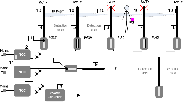
2 System overview
Figure 1 Functional system overview
The system consists of the following components:
1. X2 Rx/Tx Unit
2. NCC unit for communication
3. Power inserter
4. Antenna frame 27 cm Model: PG27
5. Antenna frame 39 cm Model: PG39
6. Antenna frame 30 cm Model: FL30
7. Antenna frame 45 cm Model: FL45
8. Antenna frame 37 cm Model: W37-CC
9. Antenna frame 45 cm Model: EQ45-F Floor antenna
10. Customer Counting unit including Lighting
11. Optional communication units:
• PSTN: MT5600SMI-92 by Multitech CE approved, Canada IC: 125 11142A and USA FCC complies
with 47 CFR Part 68: AU7USA-46014-MD-E or any other CE, FCC and IC approved PSTN.
• GSM/GPRS: MTSMC–G-F4 by Multitech CE approved , Canada IC: 125A-0027 and USA FCC ID:
AU79U07A31817 or any other approved FCC or IC approved GSM
• LAN: XPORT by Lantronix
• WiFi: IEEE 802.11b WiPort 485 by Lantronix FCC ID: R68WIPORTG IC-ID:3867A-WIPORTG
The X2 system is complete wired up and ready for use. You only have to follow up the next steps:
• Install the X2 system according the X2 Electronics Manual;
• Distance between an antenna and a wall, door, sliding door etc. must be at least 0.2 m;
• Distance between an antenna and the nearest tagged item must be at least 2 m;
• Reading range totally (split up in two antenna sides) when using:
o hard tags Ø50 mm and FL30 antennas is: 1.80 m;
o paper tags 40x40 mm and FL30 antennas is: 1.40 m;
o hard tags Ø50 mm and FL45 antennas is: 2.30 m;
o paper tags 40x40 mm and FL45 antennas is: 1.80 m;
o hard tags Ø50 mm and PG27 antennas is: 2.00 m;
o paper tags 40x40 mm and PG27 antennas is: 1.50 m
o hard tags Ø50 mm and PG39 antennas is: 2.60 m;
o paper tags 40x40 mm and PG39 antennas is: 2.00 m;
o hard tags Ø50 mm and W37-CC antennas is: 2.60 m;
o paper tags 40x40 mm and W37-CC antennas is: 2.00 m;
o hard tags Ø50 mm and EQ45-F antennas is: 1.00 m;
Page 7 of 9
o paper tags 40x40 mm and EQ45-F antennas is: 0.75 m;
• Power up the X2 system
• Check the functionality;
• Call Nedap Customer Support for quick hands-on problem solution in case of unforeseen problems
[see Technical Support];
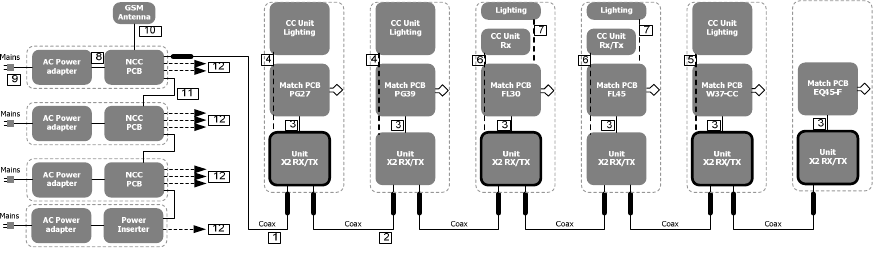
3 Wiring diagram
Schematically diagrams below shows an example of the connections between used modules.
The picture shows the full configuration that can be built up.
Ant.
Ant.
Ant.
Ant.
Ant.
Ant.
Figure 2 Example full configuration
The connections for a full configuration are:
1. Datacom cable for NCC to Unit X2
Connects Data communication and power from NCC [9203508] to a Unit X2 RX/TX [9938176]
2. Datacom cable between Unit X2 to second Unit X2
Connects the data and power between the X2 RX/TX Units.
3. Coax cable
Connects the antenna Match PCBA to X2 RX/TX unit [9938176] for the EAS antennas PG27, PG39, FL30,
FL45, W37-CC and EQ45-F
4. Cable for Cusomer counting and lighting unit PG27/PG39
Connects the X2 RX/TX [9938176] to the Customer Counter and lighting unit [7833342]
5. Cable for Cusomer counting and lighting unit W37-CC
Connects the X2 RX/TX [9938176] to the Customer Counter and lighting unit [7835361]
6. Cable for Cusomer counting and lighting unit FL30/FL45
Connects the X2 RX/TX [9938176] to one of the Customer counter units [9923373, 9928529, 9936114,
9935207]
7. Cable for lighting module FL30/FL45
Connects the X2 RX/TX [9938176] to the lighting module
8. DC cable from Power adapter to NCC electronics
Connects the Power-adapter [9651543] to the NCC main board [7824785] and carries 33V DC power
9. Mains cable
Connects the Mains power to the Power-adapter [9651543]
10. Coax cable for GSM antenna
Connects the GSM module to the GSM external antenna to contact the GSM network.
11. Datacom cables to slave NCC’s
Connects a NCC with the behavior “Master” to NCC devices with the behavior “Slave”
12. Datacom cables for system expansion
Connects more antenna strings up to 16 devices with the same function as Wire 1 and 2

Page 8 of 9
4. FCC/IC Declarations
4 FCC/IC Declarations
Compl
i
ance statements (part15.19)
This device complies with part 15 of the FCC Rules and to RSS210 of Industry Canada.
Operation is subject to the following two conditions:
(1) this device may not cause harmful interference, and
(2) this device must accept any interference received, including interference that may cause
undesired operation.
Cet appareil se conforme aux normes RSS210 exemptés de license du Industry Canada.
L'opération est soumis aux deux conditions suivantes:
(1) cet appareil ne doit causer aucune interférence, et
(2) cet appareil doit accepter n'importe quelle interférence, y inclus interférence qui peut
causer une opération non pas voulu de cet appareil.
Warning (part15.21)
Changes or modifications not expressly approved by party responsible for compliance could
void the user’s authority to operate the equipment.
This in particular is applicable for the antenna which can be delivered with the X2 System.
Information to the User (Part 15.106(b))
Note: This equipment has been tested and found to comply with the limits for a class B digital
devices, pursuant to part 15 of the FCC Rules. These limits are designed to provide
reasonable protection against harmful interference in a residential installation. This equipment
generates, uses and can radiate radio frequent energy and, if not installed and used in
accordance with the instructions, may cause harmful interference to radio communications.
However, there is no guarantee that interference will not occur in a particular installation. If this
equipment does not cause harmful interference to radio or television reception, which can be
determine by turning the equipment off and on , the user is encouraged to try to correct the
interference by one or more of the following measures:
- Reorient or relocate the receiving antenna.
- Increase the separation between the equipment and receiver.
- Connect the equipment into an outlet on a circuit different from that to which the receiver is
connected.
- Consult the dealer or an experienced radio/TV technician for help.
Page 9 of 9
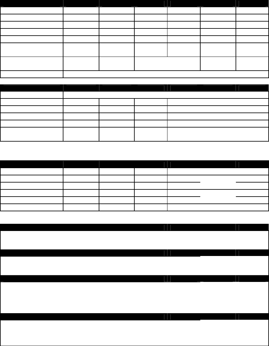
5 Specifications X2.
Enviromental
Description PG27 PG27 PG39 FL30 FL45 W37-CC EQ45-F
Antenna Hight (in mm) 1533 1670 1665 1665 1500 1800
Antenna With (in mm) 273 390 322 462 370 700
Antenna Base (in mm) 104 104 100 100 55
Frame thickness (in mm) 20 20 70 70 40 67
Weight (in kg) 13 20 12 15 8 10
Material Construction PMMA* PMMA Al** Al**
Al**
Copper Polycarbonate
Material Covers Stainles Steel
Stainless
Steel
ABS*** HI-121, Stainless
Steel Eternit Calibre 201-15
Protection Class IP20
*PMMA= Polymethylmethacrylaat **AL=Aluminum ***ABS= Acrylonitril-butadieen-styreen
Description
Min. Typical Max. Condition
Operating frequency 7.4 MHz 8.8 MHz
Operational temperature 0°C 40 °C
Storage temperature -10°C +70°C
Relative Humidity 20% 90% non-condensing
Operating Distance 0.9m 2.4m
Tag and Antenna dependant
see Section 2
Input Requirements and electrical specifications
Description Min. Typical Max. Condition
Input Voltage 100VAC 240VAC Full Range; 50/60Hz
Input Current - - 2A 90VAC 50Hz
Line Frequency 47 Hz 50-60Hz 63Hz -
Inrush Current @25°C 60A 230VAC Cold Start
Operation Voltage 29.1VDC 30VDC 30.9VDC
Power 0 W 30W 230VAC 50Hz
Regulations
Safety approvals of the Power Adapter:
· cULus according to UL/CSA 60950-1
· Japan PSE
· CE Europe according to EN60950-1
Telecom system approval
· Canada IC ID according to RSS210 IC ID: 1444A-
· US according to FCC Part 15 FCC ID: CGD
· CE according to EN 300 330
In compliance with Human exposure assessment according to:
· EN62369-1 and EN50364
· ICNIRP Guidelines
· IEEE C95.1
· RSS102
· ARIB STD-38
Electromagnetic compatibility
· EN 301 489
· IEC 61000-6-2
· IEC 61000-6-3
· CISPR 22 / EN55022