Nedap N V X2 Anti-Pilferage Device User Manual 02
N. V. Nederlandsche Apparatenfabriek NEDAP Anti-Pilferage Device 02
Contents
- 1. User Manual 01
- 2. User Manual 02
- 3. User Manual 03
User Manual 02

- 1 -
manual
X2 Electronics
Februari 2012
- 2 -
Technical Support
E-Mail : support-rs@nedap.com
Safety precautions
CAUTION - RISK OF ELECTRIC SHOCK - DO NOT OPEN
CAUTION: TO REDUCE THE RISK OF ELECTRICAL SHOCK, DO NOT REMOVE COVER (OR BACK). NO USER-SERV-
ICEABLE PARTS INSIDE. REFER SERVICING TO QUALIFIED NEDAP SERVICE PERSONNEL.
Lightning ash with an arrowhead, enclosed in a triangle, alerts you to the presence of uninsulated volt-
age points inside the product which could cause a serious electrical shock.
An exclamation mark enclosed in a triangle alerts you to important operating and maintenance instruc-
tions in the documentation provided with the product.
WARNING! To avoid the risk of re or electrical shock, never expose these products to water or operate in a high humidity
environment.
EN 50419:2005
EN 50419:2005 This European Standard species a marking
• of electrical and electronic equipment in accordance with Article 11(2) of Directive 2002/96/EC
(WEEE); This is in addition to the marking requirement in Article 10(3) of this Directive which re-
quires producers to mark electrical and electronic equipment put on the market after 13 August
2005 with a ‘crossed-out wheeled bin’ symbol.
• that applies to electrical and electronic equipment falling under Annex IA of Directive 2002/96/
EC, provided the equipment concerned is not part of another type of equipment that does not fall
within the scope of this Directive. Annex IB of Directive 2002/96/EC contains an indicative list of the
products, which fall under the categories set out in Annex IA of this Directive;
• that serves to clearly identify the producer of the equipment and that the equipment has been put
on the market after 13 August 2005.
© 2009 Nedap Retail Support Netherlands Parallelweg 2d, 7141 DC Groenlo
The software / hardware described in this book / le is furnished under a license agreement and may be used only in accord-
ance with the terms of the agreement.
Documentation version SAFETY Manual X2 2012
Copyright Notice
All Rights Reserved. Any technical documentation that is made available by Nedap Retail Support is the copyrighted work of Nedap Retail Support and is owned by Nedap Retail Support.
No warranty The technical documentation is being delivered to you and Nedap Retail Support makes no warranty as to its accuracy or use. Any use of the technical documentation or the
information contained therein is at the risk of the user. Documentation may include technical or other inaccuracies or typographical errors Nedap Retail Support the right to make changes
without prior notice. No part of this publication may be copied without the express written permission of Nedap Retail Support, Parallelweg 2d, 7141 DC Groenlo, Netherlands
Trademarks Nedap, the Nedap logo, Nedap EASi/Net and the Nedap EASi/Net are registered trademarks of Nedap N.V. Groenlo.
Other product names mentioned in this manual may be trademarks or registered trademarks of their respective companies and are hereby acknowledged.
Digital Printed in the Netherlands

- 3 -
Table of Contents
2 Technical Support
2 Safety precautions
2 Copyright Notice
4 1. Introduction
4 1.1 Communication functions
4 1.2 Customer Counting
4 1.3 Key Switch
4 1.4 Crying Funtion
5 1.5 Benets
5 1.6 Software version
6 2. Block diagram SDR PCB
6 2.1 Network communication control
6 2.1.1 Hand-terminal-connection
6 2.1.2 Data communication over coax and Power
6 2.2 Anti-deactivation regulation (Detection mode)
6 2.3 Tag Analyzer
6 2.4 Transceiver section
7 2.5 Master - Slave settings and status LEDs
7 2.5.1 View X2 electronics Status
7 2.5.2 Change X2 functionality
7 2.6 X2 approved antennas
7 2.7 Data communication
8 2.8 Customer counting
8 2.9 DC Power Supply
9 3. PCB Components overview
9 3.1 Connector overview
9 3.2 LED overview
10 4. Unit address
10 5. Connection to PC / Laptop
11 6.CongurationManager
11 6.1 PL TAB
11 6.2 PL RX TAB
11 6.3 PL TX TAB
12 6.4 PL Sync TAB
13 6.5 PL Alarm TAB
13 6.6 ASC
13 6.7 Spectrum analyzer
15 7.Systemconguration
15 7.1 Medium scale installation example
17 8.SpecicationsX2
- 4 -
1. Introduction
• System adapt to any environment
• Cognitive (Radio) system (Software Dened Radio)
• It monitors the utilization of the RF spectrum in the neighborhood, and congures it self for best performance
• Quickly and easily upgradeable with enhanced features
• Can be recongured “on-the-y”: Detection or label analyzer
Software radio is the art and science of building radios using software. By radio, we
mean any kind of device that intentionally transmits or receives signals in the radio
frequency (RF) part of the electromagnetic spectrum.
Given the constraints of today’s technology, there is still some RF hardware
involved, but the idea is to get the software as close to the antenna as is feasible.
Ultimately, we’re turning hardware solutions into software solutions.
The label analyzer has an increased detection range, and has a quick detection
and deactivation including important information like accurate Q and frequency
measurement. It can also measure differences in deactivation levels.
The detection system can function without NCC and can be switched into a master.
1.1 Communication functions
Communication remote assistance or data delivery is done by use of an NCC MK2 master unit. There are no
onboard communication functions. With a combination of customer counting and above capabilities you can use,
alter and monitor remote-diagnostics, rmware-upgrade and system
congurations.
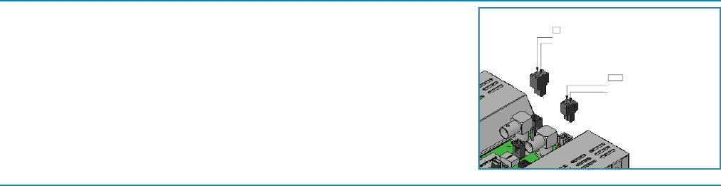
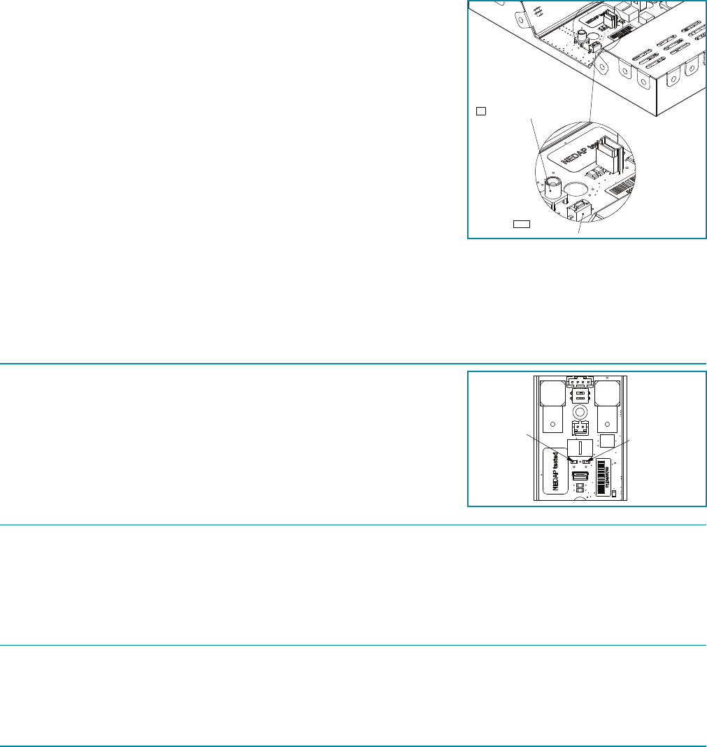
To communicate with the Nedap Conguration Manager, a connection through
USB has to be established. This is a connection between the onboard Mini-USB
connector K210 and an USB connector in the PC or laptop.
1.2 Customer Counting
The X2 PCB has Customer Counting possibilities for one aisle. Gathered data can be shown on the Easinet™.
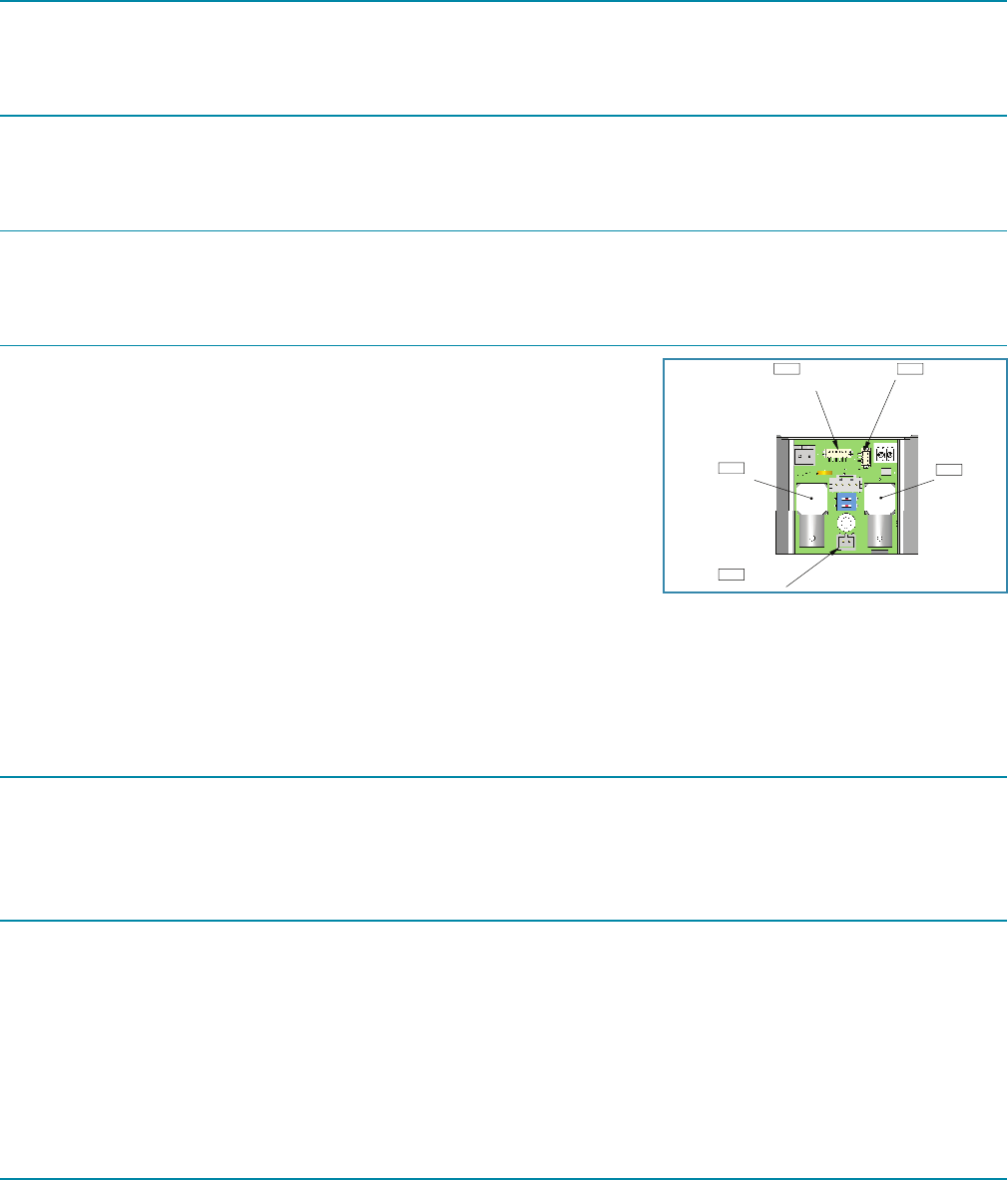
1.3 Key Switch
The X2 can be tted with an Key Switch. The switch has to be connected to K208
(for connector images, see 1.2 Customer Counting).
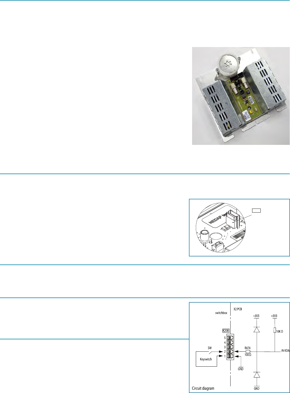
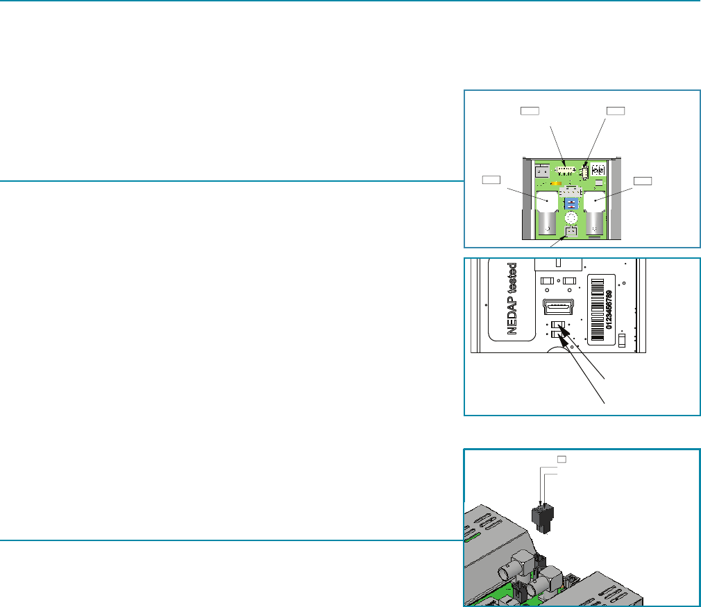
1.4 Crying Funtion
X2 electronics are standard tted with a buzzer for the crying function. The buzzer
will be connected to connector K206.
The buzzer is tted to a mounting plate.
External
USB(mini) cong port
K210
- 5 -
1.5 Benets
• 1 aisle CC option (K208)
• 1 opto input for key switch (K208)
• Standard delivered with a buzzer for use of the crying function option (K206)
• Conguration Manager connection by USB
1.6 Software version
The latest version of the Conguration Manager must be installed for use with the new electronics The sweep time has
changed, there fore all units in a system must have rmware version 2.xxx or higher!
X2
Unit X2 Cable 2 FR + MD
A
C
-
A
YYYY-MM-DD
Documentation released
-
Ref.Nr.
REV.
DATE
DESCRIPTION
APPROVED
N/A
DIM. IN MM
ROUGHNESS ACC.
ISO 1302 in µM
GENERAL TOLERANCES
SCALE:
FORMAT:
DRAWING:
Copyright (c) by N.V. Nederlandsche Apparatenfabriek NEDAP. No part of this
drawing may be reproduced or distributed in any form or by any means, or stored
in a data base or retrieval system without the prior written permission of NEDAP.
A
B
C
D
E
F
6
3
2
5
6
7
8
A3
8017328
N/A
A.01
ARTICLE NUMBER
REV.
ISO A
GROENLO HOLLAND
SHEET:
4
7
8
5
4
3
2
10.01 OF 1
1:2
± 1°
± 0.2
DESCRIPTION
LIN.
ANG.
N/A
??
??
??
DRW:
CHCK:
YYYY-MM-DD
YYYY-MM-DD
YYYY-MM-DD
DSGN:
A
YYYY-MM-DD
Documentation released
Ref.Nr.
REV.
DATE
DESCRIPTION
APPROVED
N/A
DIM. IN MM
ROUGHNESS ACC.
ISO 1302 in µM
GENERAL TOLERANCES
SCALE:
FORMAT:
DRAWING:
Copyright (c) by N.V. Nederlandsche Apparatenfabriek NEDAP. No part of this
drawing may be reproduced or distributed in any form or by any means, or stored
in a data base or retrieval system without the prior written permission of NEDAP.
A
B
C
D
E
F
4
3
2
1
F
E
D
C
B
A
1
2
3
4
A4
8017336
N/A
A
ARTICLE NUMBER
REV.
ISO A
GROENLO HOLLAND
SHEET:
N/A
± 0.2
± 1°
1:1
10.01 OF 1
DESCRIPTION
LIN.
ANG.
DSGN:
??
??
DRW:
CHCK:
2009-MM-DD
2009-MM-DD
2009-MM-DD
??
Buzzer with cable
A
YYYY-MM-DD
Documentation released
Ref.Nr.
REV.
DATE
DESCRIPTION
APPROVED
N/A
DIM. IN MM
ROUGHNESS ACC.
ISO 1302 in µM
GENERAL TOLERANCES
SCALE:
FORMAT:
DRAWING:
Copyright (c) by N.V. Nederlandsche Apparatenfabriek NEDAP. No part of this
drawing may be reproduced or distributed in any form or by any means, or stored
in a data base or retrieval system without the prior written permission of NEDAP.
A
B
C
D
E
F
4
3
2
1
F
E
D
C
B
A
1
2
3
4
A4
4092201-rs
N/A
A
ARTICLE NUMBER
REV.
ISO A
GROENLO HOLLAND
SHEET:
N/A
± 0.2
± 1°
1:1
10.01 OF 1
DESCRIPTION
LIN.
ANG.
DSGN:
??
??
DRW:
CHCK:
2009-MM-DD
2009-MM-DD
2009-MM-DD
??
A
YYYY-MM-DD
Documentation released
Ref.Nr.
REV.
DATE
DESCRIPTION
APPROVED
N/A
DIM. IN MM
ROUGHNESS ACC.
ISO 1302 in µM
GENERAL TOLERANCES
SCALE:
FORMAT:
DRAWING:
Copyright (c) by N.V. Nederlandsche Apparatenfabriek NEDAP. No part of this
drawing may be reproduced or distributed in any form or by any means, or stored
in a data base or retrieval system without the prior written permission of NEDAP.
A
B
C
D
E
F
F
E
D
C
B
A
1
2
3
4
A4
4092201-rs
N/A
A
ARTICLE NUMBER
REV.
ISO A
GROENLO HOLLAND
SHEET:
N/A
± 0.2
± 1°
1:1
10.01 OF 1
DESCRIPTION
LIN.
ANG.
DSGN:
??
??
DRW:
CHCK:
2009-MM-DD
2009-MM-DD
2009-MM-DD
??
2x M3x10 2x M4x10
A
YYYY-MM-DD
Documentation released
Ref.Nr.
REV.
DATE
DESCRIPTION
APPROVED
N/A
DIM. IN MM
ROUGHNESS ACC.
ISO 1302 in µM
GENERAL TOLERANCES
SCALE:
FORMAT:
DRAWING:
Copyright (c) by N.V. Nederlandsche Apparatenfabriek NEDAP. No part of this
drawing may be reproduced or distributed in any form or by any means, or stored
in a data base or retrieval system without the prior written permission of NEDAP.
A
B
C
D
E
F
4
3
2
1
F
E
D
C
B
A
1
2
3
4
A4
4092201-rs
N/A
A
ARTICLE NUMBER
REV.
ISO A
GROENLO HOLLAND
SHEET:
N/A
± 0.2
± 1°
1:1
10.01 OF 1
DESCRIPTION
LIN.
ANG.
DSGN:
??
??
DRW:
CHCK:
2009-MM-DD
2009-MM-DD
2009-MM-DD
??
2x M3x6
Pin 1 = Gnd
Pin 2 = +33Volt in
K1
(YELLOW)
(Not included)
Datacom error (Red)
Power on (Green)
CC 2 (Yellow)
CC 1 (Yellow)
Alarm (Yellow)
No function (2)
50
Ω (1)
ON
OFF
Master/slave switch
Antenna
(TX-out)
USB (mini) cong port
Art.No: 7706707
NC
NC
K102
Pin 2 = - buzzer (black)
Pin 1 =
+
buzzer (red)
Sync in
Sync out
Deact. buzzer
Keyswitch
Customer
counting
K206
K3
K101
K210
SW3
K209
Keyswitch
+3V3
R474
100
Ω
GND
+3V3
IN KSW
X2 PCB
External
switchbox
SW
1
2
3
4
5
10K
Ω
Circuit diagram
K208
GND
(BLUE)
(RED)
(GREEN)
+ 12V for sensors
CC sensor 2
CC sensor 1
Gnd
K211K208
(Not included)
T5276-659
DIM. IN MM
ROUGHNESS ACC.
ISO 1302 in µM
GENERAL TOLERANCES
SCALE:
FORMAT:
DRAWING:
Copyright (c) by N.V. Nederlandsche Apparatenfabriek NEDAP. No part of this
drawing may be reproduced or distributed in any form or by any means, or stored
in a data base or retrieval system without the prior written permission of NEDAP.
6
3
2
1
F
E
D
C
B
A
5
6
7
8
A3
QUICK REFERENCE X2
5276659
c
ARTICLE NUMBER
REV.
ISO A
GROENLO HOLLAND
SHEET:
4
7
8
5
4
3
2
1
45.01 OF 2
1:1
± 1°
± 0.2
DESCRIPTION
LIN.
ANG.
N/A
CB
CB
CB
DRW:
CHCK:
2009-12-18
2009-10-26
2009-10-26
DSGN:
Pin 1 = Gnd
Pin 2 = +33Volt in
K1
(YELLOW)
(Not included)
Datacom error (Red)
Power on (Green)
CC 2 (Yellow)
CC 1 (Yellow)
Alarm (Yellow)
No function (2)
50
Ω (1)
ON
OFF
Master/slave switch
Antenna
(TX-out)
USB (mini) cong port
Art.No: 7706707
NC
NC
K102
Pin 2 = - buzzer (black)
Pin 1 =
+
buzzer (red)
Sync in
Sync out
Deact. buzzer
KeyswitchCustomer
counting
K206
K3
K101
K210
SW3
K209
Keyswitch
+3V3
R474
100
Ω
GND
+3V3
IN KSW
X2 PCB
External
switchbox
SW
1
2
3
4
5
10K
Ω
Circuit diagram
K208
GND
(BLUE)
(RED)
(GREEN)
+ 12V for sensors
CC sensor 2
CC sensor 1
Gnd
K211K208
(Not included)
T5276-659
DIM. IN MM
ROUGHNESS ACC.
ISO 1302 in µM
GENERAL TOLERANCES
SCALE:
FORMAT:
DRAWING:
Copyright (c) by N.V. Nederlandsche Apparatenfabriek NEDAP. No part of this
drawing may be reproduced or distributed in any form or by any means, or stored
in a data base or retrieval system without the prior written permission of NEDAP.
A
B
C
D
E
F
6
3
2
1
F
E
D
C
B
A
5
6
7
8
A3
QUICK REFERENCE X2
5276659
c
ARTICLE NUMBER
REV.
ISO A
GROENLO HOLLAND
SHEET:
4
7
8
5
4
3
2
1
45.01 OF 2
1:1
± 1°
± 0.2
DESCRIPTION
LIN.
ANG.
N/A
CB
CB
CB
DRW:
CHCK:
2009-12-18
2009-10-26
2009-10-26
DSGN:
01
Pin 1 = Gnd
Pin 2 = +33Volt in
K1
(YELLOW)
(Not included)
Datacom error (Red)
Power on (Green)
CC 2 (Yellow)
CC 1 (Yellow)
Alarm (Yellow)
No function (2)
50
Ω (1)
ON
OFF
Master/slave switch
Antenna
(TX-out)
USB (mini) cong port
Pin 2 = - buzzer (black)
Pin 1 =
+
buzzer (red)
Sync in
Deact. buzzer
Keyswitch
Customer
counting
K206
K3
K101
K210
SW3
K209
Keyswitch
+3V3
R474
100
Ω
GND
+3V3
IN KSW
X2 PCB
External
switchbox
SW
1
2
3
4
5
10K
Ω
Circuit diagram
K208
GND
(BLUE)
(RED)
(GREEN)
+ 12V for sensors
CC sensor 2
CC sensor 1
Gnd
K211K208
(Not included)
DIM. IN MM
ROUGHNESS ACC.
ISO 1302 in µM
GENERAL TOLERANCES
SCALE:
FORMAT:
DRAWING:
Copyright (c) by N.V. Nederlandsche Apparatenfabriek NEDAP. No part of this
drawing may be reproduced or distributed in any form or by any means, or stored
in a data base or retrieval system without the prior written permission of NEDAP.
6
3
2
1
F
E
D
C
B
A
5
6
7
A3
QUICK REFERENCE X2
5276659
ARTICLE NUMBER
ISO A
GROENLO HOLLAND
SHEET:
4
7
5
4
3
2
1
45.01 OF 2
1:1
± 1°
± 0.2
DESCRIPTION
LIN.
ANG.
N/A
CB
CB
CB
DRW:
CHCK:
DSGN:
A
-
A
YYYY-MM-DD
Ref.Nr.
REV.
ROUGHNESS ACC.
3
2
1
4
5
Pin 1 = Gnd
Pin 2 = +33Volt in
K1
(YELLOW)
(Not included)
Datacom error (Red)
Power on (Green)
CC 2 (Yellow)
CC 1 (Yellow)
Alarm (Yellow)
No function (2)
50
Ω (1)
ON
OFF
Master/slave switch
Antenna
(TX-out)
USB (mini) cong port
Pin 2 = - buzzer (black)
Pin 1 =
+
buzzer (red)
Sync in
Deact. buzzer
Customer
counting
K206
K3
K101
K210
SW3
K209
Keyswitch
+3V3
R474
100
Ω
GND
+3V3
IN KSW
X2 PCB
External
switchbox
SW
1
2
3
4
5
10K
Ω
Circuit diagram
K208
GND
(BLUE)
(RED)
(GREEN)
+ 12V for sensors
CC sensor 2
CC sensor 1
Gnd
K208
DIM. IN MM
ROUGHNESS ACC.
ISO 1302 in µM
GENERAL TOLERANCES
SCALE:
FORMAT:
DRAWING:
Copyright (c) by N.V. Nederlandsche Apparatenfabriek NEDAP. No part of this
drawing may be reproduced or distributed in any form or by any means, or stored
in a data base or retrieval system without the prior written permission of NEDAP.
6
3
2
1
F
E
D
C
B
A
5
6
7
A3
QUICK REFERENCE X2
5276659
ARTICLE NUMBER
ISO A
GROENLO HOLLAND
SHEET:
4
7
5
4
3
2
1
1:1
± 1°
± 0.2
DESCRIPTION
LIN.
ANG.
N/A
DRW:
CHCK:
DSGN:
Pin 1 = Gnd
Pin 2 = +33Volt in
K1
(YELLOW)
(Not included)
Datacom error (Red)
Power on (Green)
CC 2 (Yellow)
CC 1 (Yellow)
Alarm (Yellow)
No function (2)
50
Ω (1)
ON
OFF
Master/slave switch
Antenna
(TX-out)
USB (mini) cong port
Pin 2 = - buzzer (black)
Pin 1 =
+
buzzer (red)
Sync in
Deact. buzzer
Keyswitch
Customer
counting
K206
K3
K101
K210
SW3
K209
Keyswitch
+3V3
R474
100
Ω
GND
+3V3
IN KSW
X2 PCB
External
switchbox
SW
1
2
3
4
5
10K
Ω
Circuit diagram
K208
GND
(BLUE)
(RED)
(GREEN)
+ 12V for sensors
CC sensor 2
CC sensor 1
Gnd
K211K208
DIM. IN MM
ROUGHNESS ACC.
ISO 1302 in µM
GENERAL TOLERANCES
SCALE:
FORMAT:
DRAWING:
Copyright (c) by N.V. Nederlandsche Apparatenfabriek NEDAP. No part of this
drawing may be reproduced or distributed in any form or by any means, or stored
in a data base or retrieval system without the prior written permission of NEDAP.
6
3
2
1
F
E
D
C
B
A
5
6
7
A3
QUICK REFERENCE X2
5276659
ARTICLE NUMBER
ISO A
GROENLO HOLLAND
SHEET:
4
7
5
4
3
2
1
1:1
± 1°
± 0.2
DESCRIPTION
LIN.
ANG.
N/A
CB
CB
CB
DRW:
CHCK:
DSGN:
Pin 1 = Gnd
Pin 2 = +33Volt in
K1
(YELLOW)
(Not included)
Master/slave switch
Antenna
(TX-out)
USB (mini) cong port
Art.No: 7706707
NC
NC
K102
Pin 2 = - buzzer (black)
Pin 1 =
+
buzzer (red)
Sync in
Sync out
Deact. buzzer
Keyswitch
Customer
counting
K206
K3
K101
K210
SW3
K209
(BLUE)
(RED)
(GREEN)
+ 12V for sensors
CC sensor 2
CC sensor 1
Gnd
K211K208
(Not included)
T5276-659
DIM. IN MM
ROUGHNESS ACC.
ISO 1302 in µM
GENERAL TOLERANCES
SCALE:
FORMAT:
DRAWING:
Copyright (c) by N.V. Nederlandsche Apparatenfabriek NEDAP. No part of this
drawing may be reproduced or distributed in any form or by any means, or stored
in a data base or retrieval system without the prior written permission of NEDAP.
A
B
C
D
E
F
6
5
6
7
8
A3
QUICK REFERENCE X2
5276659
c
ARTICLE NUMBER
REV.
ISO A
GROENLO HOLLAND
SHEET:
4
7
8
5
4
45.01 OF 2
1:1
± 1°
± 0.2
DESCRIPTION
LIN.
ANG.
N/A
CB
CB
CB
DRW:
CHCK:
2009-12-18
2009-10-26
2009-10-26
DSGN:
- 6 -
2. Block diagram SDR PCB
The X2 PCB combines the communication control unit, the transmitter and receiver in one single unit.
2.1 Network communication control
For network communication an external NCC (NCC MK2, SQ) is necessary.
2.1.1 Hand-terminal-connection
The use of a handheld terminal is not available for the X2 unit.
2.1.2 data communication over coax and Power
One of the important features of the X2 electronics is the data-com over the coax
cable. With this feature it’s not necessary to use an extra data-cable between the
units, which simplies the installation of the system. An NCC MK2 unit plays a
central roll in providing the data-com. All the connected units are interrogated
periodically by this unit. If there are messages like an alarm on a connected X2
unit, then the NCC MK2 unit will process this and takes the necessary action:
Sending a command to turn on the lamps on the activated aisle.
The X2 has two slave-sync connectors (K101 and K102) from which the unit can be
driven from a NCC MK2, SQ, DQ or another networking unit.
X2 electronics can also act as a stand-alone unit, without the need for any synchronization. DC power supply always from its
own Master DC input connector K3 or from the power inserter.
2.2 Anti-deactivation regulation (Detection mode)
To prevent unwanted deactivation during detection of a label, the transmitted power will be reduced when a label is in its
proximity. It is a high speed loop. The user will not notice a difference in response.
2.3 Tag Analyzer
In tag analyzer mode, the power is constant. The tag analyzer has the ability to detect, store label information, like accurate Q
and frequency measurement. It can also measure differences in deactivation levels.
By using a piezo a label can be detected, the signal strength will be visualized by a repeating audio signal. When a label is
no longer detected, the gathered information will be stored. When a low Q label is detected, the transmitter signal will be
increased; the label will be quicker deactivated.
2.4 Transceiver section
The X2 makes use of the pulse (transmitter) and listen (receiver) technique. This is the same technique used with radar. This
gives the freedom to use it with mono-antennas.
The X2 uses a transceiver architecture that gives the highest exibility possible today. The analog signal from the antenna is
almost directly converted to digital domain. The transmitter signal is just before the antenna converted to analog.
The analog to digital converter (ADC) has a high dynamic range and runs on a high frequency. This gives the possibility to
handle strong interference without clipping/distorting the wanted label signal in the receiver.
The antenna is connected to K1.
When a single unit X2 is stand-alone no synchronization is necessary. In all other situations the transceiver needs to be
synchronized for best performance.
X2
Unit X2 Cable 2 FR + MD
A
C
-
A
YYYY-MM-DD
Documentation released
-
Ref.Nr.
REV.
DATE
DESCRIPTION
APPROVED
N/A
DIM. IN MM
ROUGHNESS ACC.
ISO 1302 in µM
GENERAL TOLERANCES
SCALE:
FORMAT:
DRAWING:
Copyright (c) by N.V. Nederlandsche Apparatenfabriek NEDAP. No part of this
drawing may be reproduced or distributed in any form or by any means, or stored
in a data base or retrieval system without the prior written permission of NEDAP.
A
B
C
D
E
F
6
3
2
5
6
7
8
A3
8017328
N/A
A.01
ARTICLE NUMBER
REV.
ISO A
GROENLO HOLLAND
SHEET:
4
7
8
5
4
3
2
10.01 OF 1
1:2
± 1°
± 0.2
DESCRIPTION
LIN.
ANG.
N/A
??
??
??
DRW:
CHCK:
YYYY-MM-DD
YYYY-MM-DD
YYYY-MM-DD
DSGN:
A
YYYY-MM-DD
Documentation released
Ref.Nr.
REV.
DATE
DESCRIPTION
APPROVED
N/A
DIM. IN MM
ROUGHNESS ACC.
ISO 1302 in µM
GENERAL TOLERANCES
SCALE:
FORMAT:
DRAWING:
Copyright (c) by N.V. Nederlandsche Apparatenfabriek NEDAP. No part of this
drawing may be reproduced or distributed in any form or by any means, or stored
in a data base or retrieval system without the prior written permission of NEDAP.
A
B
C
D
E
F
4
3
2
1
F
E
D
C
B
A
1
2
3
4
A4
8017336
N/A
A
ARTICLE NUMBER
REV.
ISO A
GROENLO HOLLAND
SHEET:
N/A
± 0.2
± 1°
1:1
10.01 OF 1
DESCRIPTION
LIN.
ANG.
DSGN:
??
??
DRW:
CHCK:
2009-MM-DD
2009-MM-DD
2009-MM-DD
??
Buzzer with cable
A
YYYY-MM-DD
Documentation released
Ref.Nr.
REV.
DATE
DESCRIPTION
APPROVED
N/A
DIM. IN MM
ROUGHNESS ACC.
ISO 1302 in µM
GENERAL TOLERANCES
SCALE:
FORMAT:
DRAWING:
Copyright (c) by N.V. Nederlandsche Apparatenfabriek NEDAP. No part of this
drawing may be reproduced or distributed in any form or by any means, or stored
in a data base or retrieval system without the prior written permission of NEDAP.
A
B
C
D
E
F
4
3
2
1
F
E
D
C
B
A
1
2
3
4
A4
4092201-rs
N/A
A
ARTICLE NUMBER
REV.
ISO A
GROENLO HOLLAND
SHEET:
N/A
± 0.2
± 1°
1:1
10.01 OF 1
DESCRIPTION
LIN.
ANG.
DSGN:
??
??
DRW:
CHCK:
2009-MM-DD
2009-MM-DD
2009-MM-DD
??
A
YYYY-MM-DD
Documentation released
Ref.Nr.
REV.
DATE
DESCRIPTION
APPROVED
N/A
DIM. IN MM
ROUGHNESS ACC.
ISO 1302 in µM
GENERAL TOLERANCES
SCALE:
FORMAT:
DRAWING:
Copyright (c) by N.V. Nederlandsche Apparatenfabriek NEDAP. No part of this
drawing may be reproduced or distributed in any form or by any means, or stored
in a data base or retrieval system without the prior written permission of NEDAP.
A
B
C
D
E
F
F
E
D
C
B
A
1
2
3
4
A4
4092201-rs
N/A
A
ARTICLE NUMBER
REV.
ISO A
GROENLO HOLLAND
SHEET:
N/A
± 0.2
± 1°
1:1
10.01 OF 1
DESCRIPTION
LIN.
ANG.
DSGN:
??
??
DRW:
CHCK:
2009-MM-DD
2009-MM-DD
2009-MM-DD
??
2x M3x10 2x M4x10
A
YYYY-MM-DD
Documentation released
Ref.Nr.
REV.
DATE
DESCRIPTION
APPROVED
N/A
DIM. IN MM
ROUGHNESS ACC.
ISO 1302 in µM
GENERAL TOLERANCES
SCALE:
FORMAT:
DRAWING:
Copyright (c) by N.V. Nederlandsche Apparatenfabriek NEDAP. No part of this
drawing may be reproduced or distributed in any form or by any means, or stored
in a data base or retrieval system without the prior written permission of NEDAP.
A
B
C
D
E
F
4
3
2
1
F
E
D
C
B
A
1
2
3
4
A4
4092201-rs
N/A
A
ARTICLE NUMBER
REV.
ISO A
GROENLO HOLLAND
SHEET:
N/A
± 0.2
± 1°
1:1
10.01 OF 1
DESCRIPTION
LIN.
ANG.
DSGN:
??
??
DRW:
CHCK:
2009-MM-DD
2009-MM-DD
2009-MM-DD
??
2x M3x6
Pin 1 = Gnd
Pin 2 = +33Volt in
K1
(YELLOW)
(Not included)
Datacom error (Red)
Power on (Green)
CC 2 (Yellow)
CC 1 (Yellow)
Alarm (Yellow)
No function (2)
50
Ω (1)
ON
OFF
Master/slave switch
Antenna
(TX-out)
USB (mini) cong port
Art.No: 7706707
NC
NC
K102
Pin 2 = - buzzer (black)
Pin 1 =
+
buzzer (red)
Sync in
Sync out
Deact. buzzer
Keyswitch
Customer
counting
K206
K3
K101
K210
SW3
K209
Keyswitch
+3V3
R474
100
Ω
GND
+3V3
IN KSW
X2 PCB
External
switchbox
SW
1
2
3
4
5
10K
Ω
Circuit diagram
K208
GND
(BLUE)
(RED)
(GREEN)
+ 12V for sensors
CC sensor 2
CC sensor 1
Gnd
K211K208
(Not included)
T5276-659
DIM. IN MM
ROUGHNESS ACC.
ISO 1302 in µM
GENERAL TOLERANCES
SCALE:
FORMAT:
DRAWING:
Copyright (c) by N.V. Nederlandsche Apparatenfabriek NEDAP. No part of this
drawing may be reproduced or distributed in any form or by any means, or stored
in a data base or retrieval system without the prior written permission of NEDAP.
6
3
2
1
F
E
D
C
B
A
5
6
7
8
A3
QUICK REFERENCE X2
5276659
c
ARTICLE NUMBER
REV.
ISO A
GROENLO HOLLAND
SHEET:
4
7
8
5
4
3
2
1
45.01 OF 2
1:1
± 1°
± 0.2
DESCRIPTION
LIN.
ANG.
N/A
CB
CB
CB
DRW:
CHCK:
2009-12-18
2009-10-26
2009-10-26
DSGN:
Pin 1 = Gnd
Pin 2 = +33Volt in
K1
(YELLOW)
(Not included)
Datacom error (Red)
Power on (Green)
CC 2 (Yellow)
CC 1 (Yellow)
Alarm (Yellow)
No function (2)
50
Ω (1)
ON
OFF
Master/slave switch
Antenna
(TX-out)
USB (mini) cong port
Art.No: 7706707
NC
NC
K102
Pin 2 = - buzzer (black)
Pin 1 =
+
buzzer (red)
Sync in
Sync out
Deact. buzzer
Keyswitch
Customer
counting
K206
K3
K101
K210
SW3
K209
Keyswitch
+3V3
R474
100
Ω
GND
+3V3
IN KSW
X2 PCB
External
switchbox
SW
1
2
3
4
5
10K
Ω
Circuit diagram
K208
GND
(BLUE)
(RED)
(GREEN)
+ 12V for sensors
CC sensor 2
CC sensor 1
Gnd
K211K208
(Not included)
T5276-659
DIM. IN MM
ROUGHNESS ACC.
ISO 1302 in µM
GENERAL TOLERANCES
SCALE:
FORMAT:
DRAWING:
Copyright (c) by N.V. Nederlandsche Apparatenfabriek NEDAP. No part of this
drawing may be reproduced or distributed in any form or by any means, or stored
in a data base or retrieval system without the prior written permission of NEDAP.
A
B
C
D
E
F
6
3
2
1
F
E
D
C
B
A
5
6
7
8
A3
QUICK REFERENCE X2
5276659
c
ARTICLE NUMBER
REV.
ISO A
GROENLO HOLLAND
SHEET:
4
7
8
5
4
3
2
1
45.01 OF 2
1:1
± 1°
± 0.2
DESCRIPTION
LIN.
ANG.
N/A
CB
CB
CB
DRW:
CHCK:
2009-12-18
2009-10-26
2009-10-26
DSGN:
01
Pin 1 = Gnd
Pin 2 = +33Volt in
K1
(YELLOW)
(Not included)
Datacom error (Red)
Power on (Green)
CC 2 (Yellow)
CC 1 (Yellow)
Alarm (Yellow)
No function (2)
50
Ω (1)
ON
OFF
Master/slave switch
Antenna
(TX-out)
USB (mini) cong port
Pin 2 = - buzzer (black)
Pin 1 =
+
buzzer (red)
Sync in
Deact. buzzer
Keyswitch
Customer
counting
K206
K3
K101
K210
SW3
K209
Keyswitch
+3V3
R474
100
Ω
GND
+3V3
IN KSW
X2 PCB
External
switchbox
SW
1
2
3
4
5
10K
Ω
Circuit diagram
K208
GND
(BLUE)
(RED)
(GREEN)
+ 12V for sensors
CC sensor 2
CC sensor 1
Gnd
K211K208
(Not included)
DIM. IN MM
ROUGHNESS ACC.
ISO 1302 in µM
GENERAL TOLERANCES
SCALE:
FORMAT:
DRAWING:
Copyright (c) by N.V. Nederlandsche Apparatenfabriek NEDAP. No part of this
drawing may be reproduced or distributed in any form or by any means, or stored
in a data base or retrieval system without the prior written permission of NEDAP.
6
3
2
1
F
E
D
C
B
A
5
6
7
A3
QUICK REFERENCE X2
5276659
ARTICLE NUMBER
ISO A
GROENLO HOLLAND
SHEET:
4
7
5
4
3
2
1
45.01 OF 2
1:1
± 1°
± 0.2
DESCRIPTION
LIN.
ANG.
N/A
CB
CB
CB
DRW:
CHCK:
DSGN:
A
-
A
YYYY-MM-DD
Ref.Nr.
REV.
ROUGHNESS ACC.
3
2
1
4
5
Pin 1 = Gnd
Pin 2 = +33Volt in
K1
(YELLOW)
(Not included)
Datacom error (Red)
Power on (Green)
CC 2 (Yellow)
CC 1 (Yellow)
Alarm (Yellow)
No function (2)
50
Ω (1)
ON
OFF
Master/slave switch
Antenna
(TX-out)
USB (mini) cong port
Pin 2 = - buzzer (black)
Pin 1 =
+
buzzer (red)
Sync in
Deact. buzzer
Customer
counting
K206
K3
K101
K210
SW3
K209
Keyswitch
+3V3
R474
100
Ω
GND
+3V3
IN KSW
X2 PCB
External
switchbox
SW
1
2
3
4
5
10K
Ω
Circuit diagram
K208
GND
(BLUE)
(RED)
(GREEN)
+ 12V for sensors
CC sensor 2
CC sensor 1
Gnd
K208
DIM. IN MM
ROUGHNESS ACC.
ISO 1302 in µM
GENERAL TOLERANCES
SCALE:
FORMAT:
DRAWING:
Copyright (c) by N.V. Nederlandsche Apparatenfabriek NEDAP. No part of this
drawing may be reproduced or distributed in any form or by any means, or stored
in a data base or retrieval system without the prior written permission of NEDAP.
6
3
2
1
F
E
D
C
B
A
5
6
7
A3
QUICK REFERENCE X2
5276659
ARTICLE NUMBER
ISO A
GROENLO HOLLAND
SHEET:
4
7
5
4
3
2
1
1:1
± 1°
± 0.2
DESCRIPTION
LIN.
ANG.
N/A
DRW:
CHCK:
DSGN:
Pin 1 = Gnd
Pin 2 = +33Volt in
K1
(YELLOW)
(Not included)
Datacom error (Red)
Power on (Green)
CC 2 (Yellow)
CC 1 (Yellow)
Alarm (Yellow)
No function (2)
50
Ω (1)
ON
OFF
Master/slave switch
Antenna
(TX-out)
USB (mini) cong port
Pin 2 = - buzzer (black)
Pin 1 =
+
buzzer (red)
Sync in
Deact. buzzer
Keyswitch
Customer
counting
K206
K3
K101
K210
SW3
K209
Keyswitch
+3V3
R474
100
Ω
GND
+3V3
IN KSW
X2 PCB
External
switchbox
SW
1
2
3
4
5
10K
Ω
Circuit diagram
K208
GND
(BLUE)
(RED)
(GREEN)
+ 12V for sensors
CC sensor 2
CC sensor 1
Gnd
K211K208
DIM. IN MM
ROUGHNESS ACC.
ISO 1302 in µM
GENERAL TOLERANCES
SCALE:
FORMAT:
DRAWING:
Copyright (c) by N.V. Nederlandsche Apparatenfabriek NEDAP. No part of this
drawing may be reproduced or distributed in any form or by any means, or stored
in a data base or retrieval system without the prior written permission of NEDAP.
6
3
2
1
F
E
D
C
B
A
5
6
7
A3
QUICK REFERENCE X2
5276659
ARTICLE NUMBER
ISO A
GROENLO HOLLAND
SHEET:
4
7
5
4
3
2
1
1:1
± 1°
± 0.2
DESCRIPTION
LIN.
ANG.
N/A
CB
CB
CB
DRW:
CHCK:
DSGN:
Pin 1 = Gnd
Pin 2 = +33Volt in
K1
(YELLOW)
(Not included)
Master/slave switch
Antenna
(TX-out)
USB (mini) cong port
Art.No: 7706707
NC
NC
K102
Pin 2 = - buzzer (black)
Pin 1 =
+
buzzer (red)
Sync in
Sync out
Deact. buzzer
Keyswitch
Customer
counting
K206
K3
K101
K210
SW3
K209
(BLUE)
(RED)
(GREEN)
+ 12V for sensors
CC sensor 2
CC sensor 1
Gnd
K211K208
(Not included)
T5276-659
DIM. IN MM
ROUGHNESS ACC.
ISO 1302 in µM
GENERAL TOLERANCES
SCALE:
FORMAT:
DRAWING:
Copyright (c) by N.V. Nederlandsche Apparatenfabriek NEDAP. No part of this
drawing may be reproduced or distributed in any form or by any means, or stored
in a data base or retrieval system without the prior written permission of NEDAP.
A
B
C
D
E
F
6
5
6
7
8
A3
QUICK REFERENCE X2
5276659
c
ARTICLE NUMBER
REV.
ISO A
GROENLO HOLLAND
SHEET:
4
7
8
5
4
45.01 OF 2
1:1
± 1°
± 0.2
DESCRIPTION
LIN.
ANG.
N/A
CB
CB
CB
DRW:
CHCK:
2009-12-18
2009-10-26
2009-10-26
DSGN:
- 7 -
The receiver receives its RF reference signal and conguration data from the local
communication control section.
Transmitter:
Although the effective RF power is in the same range as our high power swept
system, the peak signals are much higher. As a consequence of that, the label
can be deactivated at larger distances from the antenna compared to the swept
system. For that reason the X2 has an RF power-control. This control will reduce it’s
transmit power when it detects a label within the deactivation range. Interferences
like a swept system will be suppressed from inuencing the power-control.
In the label analyzer mode the TX power will not decrease, but increase when a low
Q-factor label is brought into the detection eld.
Receiver:
The selectivity and dynamic range is very high. The selectivity is achieved with advanced high-speed digital lter techniques.
This gives the advantages to be able to work in environments with large level interferences.
2.5Master-SlavesettingsandstatusLEDs
Changing the unit functionality between slave and master can be done by pushing
button SW3. (See page 20)
2.5.1 view x2 electronics status
Press button SW3 1x (See page 20).
• When the yellow LED starts to blink and the red LED burns continiously, the X2 is set as a slave.
• When both LED’s are blinking, the X2 is set as master.
2.5.2 cHange x2 functionality
Press button SW3 (See page 20) 2x within 5 seconds to switch to master (or slave) status. The X2 electronics is standard
programmed as slave.
2.6 X2 approved antennas
Nedap has a broad range of antennas. Not all antennas are approved in combination with the X2 electronics. In the near
future more and more antennas will be X2 ready. It is important to know that only HIGH POWER antenna’s can be used for
safety reasons.
At the time of writing this document the following Nedap antennas are approved for use with X2 electronics:
• FL30
• FL45
• D40
• D50
• PG27
• PG39
• EQ45-F
K1
Antenna (Tx-out)
Master/slave switch
SW3
Datacom error(Red)
Alarm(Yellow)
- 8 -
2.7 Data communication
The X2 uses the same communication and synchronization signals as the sweep system of Nedap Retail. The transceiver is
a slave. Slaves are polled by the master. The communication control section, which is the master unit, polls periodically all
connected slaves and relays data to other devices e.q. other control units or PC’s.
With every sweep one slave is polled. The polled slave must answer, this happens
in the same sweep. These poll and answer data packets are used implement the
network functionality.
2.8 Customer counting
The X2 PCB is prepared with customer counting on board. 2 Sensors can be
connected to monitor 1 entrance with direction sensitivity.
The passage between sensors is shaped and buffered and processed by the
processor. In this way incoming and outgoing label alarms can be counted for
separately.
The customer counting wires can be connected to connector K208.
The sensor power output is 12 V dc. It is possible to connect sensor with positive or
negative going output signals.
Two customer counting status LED’s are situated on the PCB to indicate if the
sensors are fully functional.
2.9 DC Power Supply
Power over synchronization is possible for X2. DC supply always from its own
Master DC input connector K3 or from a power inserter .
Pin 1 = Gnd
Pin 2 = +33Volt in
K3
X2
Unit X2 Cable 2 FR + MD
A
C
-
A
YYYY-MM-DD
Documentation released
-
Ref.Nr.
REV.
DATE
DESCRIPTION
APPROVED
N/A
DIM. IN MM
ROUGHNESS ACC.
ISO 1302 in µM
GENERAL TOLERANCES
SCALE:
FORMAT:
DRAWING:
Copyright (c) by N.V. Nederlandsche Apparatenfabriek NEDAP. No part of this
drawing may be reproduced or distributed in any form or by any means, or stored
in a data base or retrieval system without the prior written permission of NEDAP.
A
B
C
D
E
F
6
3
2
5
6
7
8
A3
8017328
N/A
A.01
ARTICLE NUMBER
REV.
ISO A
GROENLO HOLLAND
SHEET:
4
7
8
5
4
3
2
10.01 OF 1
1:2
± 1°
± 0.2
DESCRIPTION
LIN.
ANG.
N/A
??
??
??
DRW:
CHCK:
YYYY-MM-DD
YYYY-MM-DD
YYYY-MM-DD
DSGN:
A
YYYY-MM-DD
Documentation released
Ref.Nr.
REV.
DATE
DESCRIPTION
APPROVED
N/A
DIM. IN MM
ROUGHNESS ACC.
ISO 1302 in µM
GENERAL TOLERANCES
SCALE:
FORMAT:
DRAWING:
Copyright (c) by N.V. Nederlandsche Apparatenfabriek NEDAP. No part of this
drawing may be reproduced or distributed in any form or by any means, or stored
in a data base or retrieval system without the prior written permission of NEDAP.
A
B
C
D
E
F
4
3
2
1
F
E
D
C
B
A
1
2
3
4
A4
8017336
N/A
A
ARTICLE NUMBER
REV.
ISO A
GROENLO HOLLAND
SHEET:
N/A
± 0.2
± 1°
1:1
10.01 OF 1
DESCRIPTION
LIN.
ANG.
DSGN:
??
??
DRW:
CHCK:
2009-MM-DD
2009-MM-DD
2009-MM-DD
??
Buzzer with cable
A
YYYY-MM-DD
Documentation released
Ref.Nr.
REV.
DATE
DESCRIPTION
APPROVED
N/A
DIM. IN MM
ROUGHNESS ACC.
ISO 1302 in µM
GENERAL TOLERANCES
SCALE:
FORMAT:
DRAWING:
Copyright (c) by N.V. Nederlandsche Apparatenfabriek NEDAP. No part of this
drawing may be reproduced or distributed in any form or by any means, or stored
in a data base or retrieval system without the prior written permission of NEDAP.
A
B
C
D
E
F
4
3
2
1
F
E
D
C
B
A
1
2
3
4
A4
4092201-rs
N/A
A
ARTICLE NUMBER
REV.
ISO A
GROENLO HOLLAND
SHEET:
N/A
± 0.2
± 1°
1:1
10.01 OF 1
DESCRIPTION
LIN.
ANG.
DSGN:
??
??
DRW:
CHCK:
2009-MM-DD
2009-MM-DD
2009-MM-DD
??
A
YYYY-MM-DD
Documentation released
Ref.Nr.
REV.
DATE
DESCRIPTION
APPROVED
N/A
DIM. IN MM
ROUGHNESS ACC.
ISO 1302 in µM
GENERAL TOLERANCES
SCALE:
FORMAT:
DRAWING:
Copyright (c) by N.V. Nederlandsche Apparatenfabriek NEDAP. No part of this
drawing may be reproduced or distributed in any form or by any means, or stored
in a data base or retrieval system without the prior written permission of NEDAP.
A
B
C
D
E
F
F
E
D
C
B
A
1
2
3
4
A4
4092201-rs
N/A
A
ARTICLE NUMBER
REV.
ISO A
GROENLO HOLLAND
SHEET:
N/A
± 0.2
± 1°
1:1
10.01 OF 1
DESCRIPTION
LIN.
ANG.
DSGN:
??
??
DRW:
CHCK:
2009-MM-DD
2009-MM-DD
2009-MM-DD
??
2x M3x10 2x M4x10
A
YYYY-MM-DD
Documentation released
Ref.Nr.
REV.
DATE
DESCRIPTION
APPROVED
N/A
DIM. IN MM
ROUGHNESS ACC.
ISO 1302 in µM
GENERAL TOLERANCES
SCALE:
FORMAT:
DRAWING:
Copyright (c) by N.V. Nederlandsche Apparatenfabriek NEDAP. No part of this
drawing may be reproduced or distributed in any form or by any means, or stored
in a data base or retrieval system without the prior written permission of NEDAP.
A
B
C
D
E
F
4
3
2
1
F
E
D
C
B
A
1
2
3
4
A4
4092201-rs
N/A
A
ARTICLE NUMBER
REV.
ISO A
GROENLO HOLLAND
SHEET:
N/A
± 0.2
± 1°
1:1
10.01 OF 1
DESCRIPTION
LIN.
ANG.
DSGN:
??
??
DRW:
CHCK:
2009-MM-DD
2009-MM-DD
2009-MM-DD
??
2x M3x6
Pin 1 = Gnd
Pin 2 = +33Volt in
K1
(YELLOW)
(Not included)
Datacom error (Red)
Power on (Green)
CC 2 (Yellow)
CC 1 (Yellow)
Alarm (Yellow)
No function (2)
50
Ω (1)
ON
OFF
Master/slave switch
Antenna
(TX-out)
USB (mini) cong port
Art.No: 7706707
NC
NC
K102
Pin 2 = - buzzer (black)
Pin 1 =
+
buzzer (red)
Sync in
Sync out
Deact. buzzer
Keyswitch
Customer
counting
K206
K3
K101
K210
SW3
K209
Keyswitch
+3V3
R474
100
Ω
GND
+3V3
IN KSW
X2 PCB
External
switchbox
SW
1
2
3
4
5
10K
Ω
Circuit diagram
K208
GND
(BLUE)
(RED)
(GREEN)
+ 12V for sensors
CC sensor 2
CC sensor 1
Gnd
K211K208
(Not included)
T5276-659
DIM. IN MM
ROUGHNESS ACC.
ISO 1302 in µM
GENERAL TOLERANCES
SCALE:
FORMAT:
DRAWING:
Copyright (c) by N.V. Nederlandsche Apparatenfabriek NEDAP. No part of this
drawing may be reproduced or distributed in any form or by any means, or stored
in a data base or retrieval system without the prior written permission of NEDAP.
6
3
2
1
F
E
D
C
B
A
5
6
7
8
A3
QUICK REFERENCE X2
5276659
c
ARTICLE NUMBER
REV.
ISO A
GROENLO HOLLAND
SHEET:
4
7
8
5
4
3
2
1
45.01 OF 2
1:1
± 1°
± 0.2
DESCRIPTION
LIN.
ANG.
N/A
CB
CB
CB
DRW:
CHCK:
2009-12-18
2009-10-26
2009-10-26
DSGN:
Pin 1 = Gnd
Pin 2 = +33Volt in
K1
(YELLOW)
(Not included)
Datacom error (Red)
Power on (Green)
CC 2 (Yellow)
CC 1 (Yellow)
Alarm (Yellow)
No function (2)
50
Ω (1)
ON
OFF
Master/slave switch
Antenna
(TX-out)
USB (mini) cong port
Art.No: 7706707
NC
NC
K102
Pin 2 = - buzzer (black)
Pin 1 =
+
buzzer (red)
Sync in
Sync out
Deact. buzzer
Keyswitch
Customer
counting
K206
K3
K101
K210
SW3
K209
Keyswitch
+3V3
R474
100
Ω
GND
+3V3
IN KSW
X2 PCB
External
switchbox
SW
1
2
3
4
5
10K
Ω
Circuit diagram
K208
GND
(BLUE)
(RED)
(GREEN)
+ 12V for sensors
CC sensor 2
CC sensor 1
Gnd
K211K208
(Not included)
T5276-659
DIM. IN MM
ROUGHNESS ACC.
ISO 1302 in µM
GENERAL TOLERANCES
SCALE:
FORMAT:
DRAWING:
Copyright (c) by N.V. Nederlandsche Apparatenfabriek NEDAP. No part of this
drawing may be reproduced or distributed in any form or by any means, or stored
in a data base or retrieval system without the prior written permission of NEDAP.
A
B
C
D
E
F
6
3
2
1
F
E
D
C
B
A
5
6
7
8
A3
QUICK REFERENCE X2
5276659
c
ARTICLE NUMBER
REV.
ISO A
GROENLO HOLLAND
SHEET:
4
7
8
5
4
3
2
1
45.01 OF 2
1:1
± 1°
± 0.2
DESCRIPTION
LIN.
ANG.
N/A
CB
CB
CB
DRW:
CHCK:
2009-12-18
2009-10-26
2009-10-26
DSGN:
Pin 1 = Gnd
Pin 2 = +33Volt in
K1
(YELLOW)
(Not included)
Datacom error (Red)
Power on (Green)
CC 2 (Yellow)
CC 1 (Yellow)
Alarm (Yellow)
No function (2)
50
Ω (1)
ON
OFF
Master/slave switch
Antenna
(TX-out)
USB (mini) cong port
Art.No: 7706707
NC
NC
K102
Pin 2 = - buzzer (black)
Pin 1 =
+
buzzer (red)
Sync in
Sync out
Deact. buzzer
Keyswitch
Customer
counting
K206
K3
K101
K210
SW3
K209
Keyswitch
+3V3
R474
100
Ω
GND
+3V3
IN KSW
X2 PCB
External
switchbox
SW
1
2
3
4
5
10K
Ω
Circuit diagram
K208
GND
(BLUE)
(RED)
(GREEN)
+ 12V for sensors
CC sensor 2
CC sensor 1
Gnd
K211K208
(Not included)
T5276-659
DIM. IN MM
ROUGHNESS ACC.
ISO 1302 in µM
GENERAL TOLERANCES
SCALE:
FORMAT:
DRAWING:
Copyright (c) by N.V. Nederlandsche Apparatenfabriek NEDAP. No part of this
drawing may be reproduced or distributed in any form or by any means, or stored
in a data base or retrieval system without the prior written permission of NEDAP.
A
B
C
D
E
F
6
3
2
1
F
E
D
C
B
A
5
6
7
8
A3
QUICK REFERENCE X2
5276659
c
ARTICLE NUMBER
REV.
ISO A
GROENLO HOLLAND
SHEET:
4
7
8
5
4
3
2
1
45.01 OF 2
1:1
± 1°
± 0.2
DESCRIPTION
LIN.
ANG.
N/A
CB
CB
CB
DRW:
CHCK:
2009-12-18
2009-10-26
2009-10-26
DSGN:
01
Pin 1 = Gnd
Pin 2 = +33Volt in
K1
(YELLOW)
(Not included)
Datacom error (Red)
Power on (Green)
CC 2 (Yellow)
CC 1 (Yellow)
Alarm (Yellow)
No function (2)
50
Ω (1)
ON
OFF
Master/slave switch
Antenna
(TX-out)
USB (mini) cong port
Pin 2 = - buzzer (black)
Pin 1 =
+
buzzer (red)
Sync in
Deact. buzzer
Keyswitch
Customer
counting
K206
K3
K101
K210
SW3
K209
Keyswitch
+3V3
R474
100
Ω
GND
+3V3
IN KSW
X2 PCB
External
switchbox
SW
1
2
3
4
5
10K
Ω
Circuit diagram
K208
GND
(BLUE)
(RED)
(GREEN)
+ 12V for sensors
CC sensor 2
CC sensor 1
Gnd
K211K208
(Not included)
DIM. IN MM
ROUGHNESS ACC.
ISO 1302 in µM
GENERAL TOLERANCES
SCALE:
FORMAT:
DRAWING:
Copyright (c) by N.V. Nederlandsche Apparatenfabriek NEDAP. No part of this
drawing may be reproduced or distributed in any form or by any means, or stored
in a data base or retrieval system without the prior written permission of NEDAP.
6
3
2
1
F
E
D
C
B
A
5
6
7
A3
QUICK REFERENCE X2
5276659
ARTICLE NUMBER
ISO A
GROENLO HOLLAND
SHEET:
4
7
5
4
3
2
1
45.01 OF 2
1:1
± 1°
± 0.2
DESCRIPTION
LIN.
ANG.
N/A
CB
CB
CB
DRW:
CHCK:
DSGN:
A
-
A
YYYY-MM-DD
Ref.Nr.
REV.
ROUGHNESS ACC.
3
2
1
4
5
Pin 1 = Gnd
Pin 2 = +33Volt in
K1
(YELLOW)
(Not included)
Datacom error (Red)
Power on (Green)
CC 2 (Yellow)
CC 1 (Yellow)
Alarm (Yellow)
No function (2)
50
Ω (1)
ON
OFF
Master/slave switch
Antenna
(TX-out)
USB (mini) cong port
Pin 2 = - buzzer (black)
Pin 1 =
+
buzzer (red)
Sync in
Deact. buzzer
Customer
counting
K206
K3
K101
K210
SW3
K209
Keyswitch
+3V3
R474
100
Ω
GND
+3V3
IN KSW
X2 PCB
External
switchbox
SW
1
2
3
4
5
10K
Ω
Circuit diagram
K208
GND
(BLUE)
(RED)
(GREEN)
+ 12V for sensors
CC sensor 2
CC sensor 1
Gnd
K208
DIM. IN MM
ROUGHNESS ACC.
ISO 1302 in µM
GENERAL TOLERANCES
SCALE:
FORMAT:
DRAWING:
Copyright (c) by N.V. Nederlandsche Apparatenfabriek NEDAP. No part of this
drawing may be reproduced or distributed in any form or by any means, or stored
in a data base or retrieval system without the prior written permission of NEDAP.
6
3
2
1
F
E
D
C
B
A
5
6
7
A3
QUICK REFERENCE X2
5276659
ARTICLE NUMBER
ISO A
GROENLO HOLLAND
SHEET:
4
7
5
4
3
2
1
1:1
± 1°
± 0.2
DESCRIPTION
LIN.
ANG.
N/A
DRW:
CHCK:
DSGN:
Pin 1 = Gnd
Pin 2 = +33Volt in
K1
(YELLOW)
(Not included)
Datacom error (Red)
Power on (Green)
CC 2 (Yellow)
CC 1 (Yellow)
Alarm (Yellow)
No function (2)
50
Ω (1)
ON
OFF
Master/slave switch
Antenna
(TX-out)
USB (mini) cong port
Pin 2 = - buzzer (black)
Pin 1 =
+
buzzer (red)
Sync in
Deact. buzzer
Keyswitch
Customer
counting
K206
K3
K101
K210
SW3
K209
Keyswitch
+3V3
R474
100
Ω
GND
+3V3
IN KSW
X2 PCB
External
switchbox
SW
1
2
3
4
5
10K
Ω
Circuit diagram
K208
GND
(BLUE)
(RED)
(GREEN)
+ 12V for sensors
CC sensor 2
CC sensor 1
Gnd
K211K208
DIM. IN MM
ROUGHNESS ACC.
ISO 1302 in µM
GENERAL TOLERANCES
SCALE:
FORMAT:
DRAWING:
Copyright (c) by N.V. Nederlandsche Apparatenfabriek NEDAP. No part of this
drawing may be reproduced or distributed in any form or by any means, or stored
in a data base or retrieval system without the prior written permission of NEDAP.
6
3
2
1
F
E
D
C
B
A
5
6
7
A3
QUICK REFERENCE X2
5276659
ARTICLE NUMBER
ISO A
GROENLO HOLLAND
SHEET:
4
7
5
4
3
2
1
1:1
± 1°
± 0.2
DESCRIPTION
LIN.
ANG.
N/A
CB
CB
CB
DRW:
CHCK:
DSGN:
Pin 1 = Gnd
Pin 2 = +33Volt in
K1
(YELLOW)
(Not included)
Master/slave switch
Antenna
(TX-out)
USB (mini) cong port
Art.No: 7706707
NC
NC
K102
Pin 2 = - buzzer (black)
Pin 1 =
+
buzzer (red)
Sync in
Sync out
Deact. buzzer
Keyswitch
Customer
counting
K206
K3
K101
K210
SW3
K209
(BLUE)
(RED)
(GREEN)
+ 12V for sensors
CC sensor 2
CC sensor 1
Gnd
K211K208
(Not included)
T5276-659
DIM. IN MM
ROUGHNESS ACC.
ISO 1302 in µM
GENERAL TOLERANCES
SCALE:
FORMAT:
DRAWING:
Copyright (c) by N.V. Nederlandsche Apparatenfabriek NEDAP. No part of this
drawing may be reproduced or distributed in any form or by any means, or stored
in a data base or retrieval system without the prior written permission of NEDAP.
A
B
C
D
E
F
6
5
6
7
8
A3
QUICK REFERENCE X2
5276659
c
ARTICLE NUMBER
REV.
ISO A
GROENLO HOLLAND
SHEET:
4
7
8
5
4
45.01 OF 2
1:1
± 1°
± 0.2
DESCRIPTION
LIN.
ANG.
N/A
CB
CB
CB
DRW:
CHCK:
2009-12-18
2009-10-26
2009-10-26
DSGN:
CC 1(Yellow)
CC 2(Yellow)
X2
Unit X2 Cable 2 FR + MD
A
C
-
A
YYYY-MM-DD
Documentation released
-
Ref.Nr.
REV.
DATE
DESCRIPTION
APPROVED
N/A
DIM. IN MM
ROUGHNESS ACC.
ISO 1302 in µM
GENERAL TOLERANCES
SCALE:
FORMAT:
DRAWING:
Copyright (c) by N.V. Nederlandsche Apparatenfabriek NEDAP. No part of this
drawing may be reproduced or distributed in any form or by any means, or stored
in a data base or retrieval system without the prior written permission of NEDAP.
A
B
C
D
E
F
6
3
2
5
6
7
8
A3
8017328
N/A
A.01
ARTICLE NUMBER
REV.
ISO A
GROENLO HOLLAND
SHEET:
4
7
8
5
4
3
2
10.01 OF 1
1:2
± 1°
± 0.2
DESCRIPTION
LIN.
ANG.
N/A
??
??
??
DRW:
CHCK:
YYYY-MM-DD
YYYY-MM-DD
YYYY-MM-DD
DSGN:
A
YYYY-MM-DD
Documentation released
Ref.Nr.
REV.
DATE
DESCRIPTION
APPROVED
N/A
DIM. IN MM
ROUGHNESS ACC.
ISO 1302 in µM
GENERAL TOLERANCES
SCALE:
FORMAT:
DRAWING:
Copyright (c) by N.V. Nederlandsche Apparatenfabriek NEDAP. No part of this
drawing may be reproduced or distributed in any form or by any means, or stored
in a data base or retrieval system without the prior written permission of NEDAP.
A
B
C
D
E
F
4
3
2
1
F
E
D
C
B
A
1
2
3
4
A4
8017336
N/A
A
ARTICLE NUMBER
REV.
ISO A
GROENLO HOLLAND
SHEET:
N/A
± 0.2
± 1°
1:1
10.01 OF 1
DESCRIPTION
LIN.
ANG.
DSGN:
??
??
DRW:
CHCK:
2009-MM-DD
2009-MM-DD
2009-MM-DD
??
Buzzer with cable
A
YYYY-MM-DD
Documentation released
Ref.Nr.
REV.
DATE
DESCRIPTION
APPROVED
N/A
DIM. IN MM
ROUGHNESS ACC.
ISO 1302 in µM
GENERAL TOLERANCES
SCALE:
FORMAT:
DRAWING:
Copyright (c) by N.V. Nederlandsche Apparatenfabriek NEDAP. No part of this
drawing may be reproduced or distributed in any form or by any means, or stored
in a data base or retrieval system without the prior written permission of NEDAP.
A
B
C
D
E
F
4
3
2
1
F
E
D
C
B
A
1
2
3
4
A4
4092201-rs
N/A
A
ARTICLE NUMBER
REV.
ISO A
GROENLO HOLLAND
SHEET:
N/A
± 0.2
± 1°
1:1
10.01 OF 1
DESCRIPTION
LIN.
ANG.
DSGN:
??
??
DRW:
CHCK:
2009-MM-DD
2009-MM-DD
2009-MM-DD
??
A
YYYY-MM-DD
Documentation released
Ref.Nr.
REV.
DATE
DESCRIPTION
APPROVED
N/A
DIM. IN MM
ROUGHNESS ACC.
ISO 1302 in µM
GENERAL TOLERANCES
SCALE:
FORMAT:
DRAWING:
Copyright (c) by N.V. Nederlandsche Apparatenfabriek NEDAP. No part of this
drawing may be reproduced or distributed in any form or by any means, or stored
in a data base or retrieval system without the prior written permission of NEDAP.
A
B
C
D
E
F
F
E
D
C
B
A
1
2
3
4
A4
4092201-rs
N/A
A
ARTICLE NUMBER
REV.
ISO A
GROENLO HOLLAND
SHEET:
N/A
± 0.2
± 1°
1:1
10.01 OF 1
DESCRIPTION
LIN.
ANG.
DSGN:
??
??
DRW:
CHCK:
2009-MM-DD
2009-MM-DD
2009-MM-DD
??
2x M3x10 2x M4x10
A
YYYY-MM-DD
Documentation released
Ref.Nr.
REV.
DATE
DESCRIPTION
APPROVED
N/A
DIM. IN MM
ROUGHNESS ACC.
ISO 1302 in µM
GENERAL TOLERANCES
SCALE:
FORMAT:
DRAWING:
Copyright (c) by N.V. Nederlandsche Apparatenfabriek NEDAP. No part of this
drawing may be reproduced or distributed in any form or by any means, or stored
in a data base or retrieval system without the prior written permission of NEDAP.
A
B
C
D
E
F
4
3
2
1
F
E
D
C
B
A
1
2
3
4
A4
4092201-rs
N/A
A
ARTICLE NUMBER
REV.
ISO A
GROENLO HOLLAND
SHEET:
N/A
± 0.2
± 1°
1:1
10.01 OF 1
DESCRIPTION
LIN.
ANG.
DSGN:
??
??
DRW:
CHCK:
2009-MM-DD
2009-MM-DD
2009-MM-DD
??
2x M3x6
Pin 1 = Gnd
Pin 2 = +33Volt in
K1
(YELLOW)
(Not included)
Datacom error (Red)
Power on (Green)
CC 2 (Yellow)
CC 1 (Yellow)
Alarm (Yellow)
No function (2)
50
Ω (1)
ON
OFF
Master/slave switch
Antenna
(TX-out)
USB (mini) cong port
Art.No: 7706707
NC
NC
K102
Pin 2 = - buzzer (black)
Pin 1 =
+
buzzer (red)
Sync in
Sync out
Deact. buzzer
Keyswitch
Customer
counting
K206
K3
K101
K210
SW3
K209
Keyswitch
+3V3
R474
100
Ω
GND
+3V3
IN KSW
X2 PCB
External
switchbox
SW
1
2
3
4
5
10K
Ω
Circuit diagram
K208
GND
(BLUE)
(RED)
(GREEN)
+ 12V for sensors
CC sensor 2
CC sensor 1
Gnd
K211K208
(Not included)
T5276-659
DIM. IN MM
ROUGHNESS ACC.
ISO 1302 in µM
GENERAL TOLERANCES
SCALE:
FORMAT:
DRAWING:
Copyright (c) by N.V. Nederlandsche Apparatenfabriek NEDAP. No part of this
drawing may be reproduced or distributed in any form or by any means, or stored
in a data base or retrieval system without the prior written permission of NEDAP.
6
3
2
1
F
E
D
C
B
A
5
6
7
8
A3
QUICK REFERENCE X2
5276659
c
ARTICLE NUMBER
REV.
ISO A
GROENLO HOLLAND
SHEET:
4
7
8
5
4
3
2
1
45.01 OF 2
1:1
± 1°
± 0.2
DESCRIPTION
LIN.
ANG.
N/A
CB
CB
CB
DRW:
CHCK:
2009-12-18
2009-10-26
2009-10-26
DSGN:
Pin 1 = Gnd
Pin 2 = +33Volt in
K1
(YELLOW)
(Not included)
Datacom error (Red)
Power on (Green)
CC 2 (Yellow)
CC 1 (Yellow)
Alarm (Yellow)
No function (2)
50
Ω (1)
ON
OFF
Master/slave switch
Antenna
(TX-out)
USB (mini) cong port
Art.No: 7706707
NC
NC
K102
Pin 2 = - buzzer (black)
Pin 1 =
+
buzzer (red)
Sync in
Sync out
Deact. buzzer
Keyswitch
Customer
counting
K206
K3
K101
K210
SW3
K209
Keyswitch
+3V3
R474
100
Ω
GND
+3V3
IN KSW
X2 PCB
External
switchbox
SW
1
2
3
4
5
10K
Ω
Circuit diagram
K208
GND
(BLUE)
(RED)
(GREEN)
+ 12V for sensors
CC sensor 2
CC sensor 1
Gnd
K211K208
(Not included)
T5276-659
DIM. IN MM
ROUGHNESS ACC.
ISO 1302 in µM
GENERAL TOLERANCES
SCALE:
FORMAT:
DRAWING:
Copyright (c) by N.V. Nederlandsche Apparatenfabriek NEDAP. No part of this
drawing may be reproduced or distributed in any form or by any means, or stored
in a data base or retrieval system without the prior written permission of NEDAP.
A
B
C
D
E
F
6
3
2
1
F
E
D
C
B
A
5
6
7
8
A3
QUICK REFERENCE X2
5276659
c
ARTICLE NUMBER
REV.
ISO A
GROENLO HOLLAND
SHEET:
4
7
8
5
4
3
2
1
45.01 OF 2
1:1
± 1°
± 0.2
DESCRIPTION
LIN.
ANG.
N/A
CB
CB
CB
DRW:
CHCK:
2009-12-18
2009-10-26
2009-10-26
DSGN:
Pin 1 = Gnd
Pin 2 = +33Volt in
K1
(YELLOW)
(Not included)
Datacom error (Red)
Power on (Green)
CC 2 (Yellow)
CC 1 (Yellow)
Alarm (Yellow)
No function (2)
50
Ω (1)
ON
OFF
Master/slave switch
Antenna
(TX-out)
USB (mini) cong port
Art.No: 7706707
NC
NC
K102
Pin 2 = - buzzer (black)
Pin 1 =
+
buzzer (red)
Sync in
Sync out
Deact. buzzer
Keyswitch
Customer
counting
K206
K3
K101
K210
SW3
K209
Keyswitch
+3V3
R474
100
Ω
GND
+3V3
IN KSW
X2 PCB
External
switchbox
SW
1
2
3
4
5
10K
Ω
Circuit diagram
K208
GND
(BLUE)
(RED)
(GREEN)
+ 12V for sensors
CC sensor 2
CC sensor 1
Gnd
K211K208
(Not included)
T5276-659
DIM. IN MM
ROUGHNESS ACC.
ISO 1302 in µM
GENERAL TOLERANCES
SCALE:
FORMAT:
DRAWING:
Copyright (c) by N.V. Nederlandsche Apparatenfabriek NEDAP. No part of this
drawing may be reproduced or distributed in any form or by any means, or stored
in a data base or retrieval system without the prior written permission of NEDAP.
A
B
C
D
E
F
6
3
2
1
F
E
D
C
B
A
5
6
7
8
A3
QUICK REFERENCE X2
5276659
c
ARTICLE NUMBER
REV.
ISO A
GROENLO HOLLAND
SHEET:
4
7
8
5
4
3
2
1
45.01 OF 2
1:1
± 1°
± 0.2
DESCRIPTION
LIN.
ANG.
N/A
CB
CB
CB
DRW:
CHCK:
2009-12-18
2009-10-26
2009-10-26
DSGN:
01
Pin 1 = Gnd
Pin 2 = +33Volt in
K1
(YELLOW)
(Not included)
Datacom error (Red)
Power on (Green)
CC 2 (Yellow)
CC 1 (Yellow)
Alarm (Yellow)
No function (2)
50
Ω (1)
ON
OFF
Master/slave switch
Antenna
(TX-out)
USB (mini) cong port
Pin 2 = - buzzer (black)
Pin 1 =
+
buzzer (red)
Sync in
Deact. buzzer
Keyswitch
Customer
counting
K206
K3
K101
K210
SW3
K209
Keyswitch
+3V3
R474
100
Ω
GND
+3V3
IN KSW
X2 PCB
External
switchbox
SW
1
2
3
4
5
10K
Ω
Circuit diagram
K208
GND
(BLUE)
(RED)
(GREEN)
+ 12V for sensors
CC sensor 2
CC sensor 1
Gnd
K211K208
(Not included)
DIM. IN MM
ROUGHNESS ACC.
ISO 1302 in µM
GENERAL TOLERANCES
SCALE:
FORMAT:
DRAWING:
Copyright (c) by N.V. Nederlandsche Apparatenfabriek NEDAP. No part of this
drawing may be reproduced or distributed in any form or by any means, or stored
in a data base or retrieval system without the prior written permission of NEDAP.
6
3
2
1
F
E
D
C
B
A
5
6
7
A3
QUICK REFERENCE X2
5276659
ARTICLE NUMBER
ISO A
GROENLO HOLLAND
SHEET:
4
7
5
4
3
2
1
45.01 OF 2
1:1
± 1°
± 0.2
DESCRIPTION
LIN.
ANG.
N/A
CB
CB
CB
DRW:
CHCK:
DSGN:
A
-
A
YYYY-MM-DD
Ref.Nr.
REV.
ROUGHNESS ACC.
3
2
1
4
5
Pin 1 = Gnd
Pin 2 = +33Volt in
K1
(YELLOW)
(Not included)
Datacom error (Red)
Power on (Green)
CC 2 (Yellow)
CC 1 (Yellow)
Alarm (Yellow)
No function (2)
50
Ω (1)
ON
OFF
Master/slave switch
Antenna
(TX-out)
USB (mini) cong port
Pin 2 = - buzzer (black)
Pin 1 =
+
buzzer (red)
Sync in
Deact. buzzer
Customer
counting
K206
K3
K101
K210
SW3
K209
Keyswitch
+3V3
R474
100
Ω
GND
+3V3
IN KSW
X2 PCB
External
switchbox
SW
1
2
3
4
5
10K
Ω
Circuit diagram
K208
GND
(BLUE)
(RED)
(GREEN)
+ 12V for sensors
CC sensor 2
CC sensor 1
Gnd
K208
DIM. IN MM
ROUGHNESS ACC.
ISO 1302 in µM
GENERAL TOLERANCES
SCALE:
FORMAT:
DRAWING:
Copyright (c) by N.V. Nederlandsche Apparatenfabriek NEDAP. No part of this
drawing may be reproduced or distributed in any form or by any means, or stored
in a data base or retrieval system without the prior written permission of NEDAP.
6
3
2
1
F
E
D
C
B
A
5
6
7
A3
QUICK REFERENCE X2
5276659
ARTICLE NUMBER
ISO A
GROENLO HOLLAND
SHEET:
4
7
5
4
3
2
1
1:1
± 1°
± 0.2
DESCRIPTION
LIN.
ANG.
N/A
DRW:
CHCK:
DSGN:
Pin 1 = Gnd
Pin 2 = +33Volt in
K1
(YELLOW)
(Not included)
Datacom error (Red)
Power on (Green)
CC 2 (Yellow)
CC 1 (Yellow)
Alarm (Yellow)
No function (2)
50
Ω (1)
ON
OFF
Master/slave switch
Antenna
(TX-out)
USB (mini) cong port
Pin 2 = - buzzer (black)
Pin 1 =
+
buzzer (red)
Sync in
Deact. buzzer
Keyswitch
Customer
counting
K206
K3
K101
K210
SW3
K209
Keyswitch
+3V3
R474
100
Ω
GND
+3V3
IN KSW
X2 PCB
External
switchbox
SW
1
2
3
4
5
10K
Ω
Circuit diagram
K208
GND
(BLUE)
(RED)
(GREEN)
+ 12V for sensors
CC sensor 2
CC sensor 1
Gnd
K211K208
DIM. IN MM
ROUGHNESS ACC.
ISO 1302 in µM
GENERAL TOLERANCES
SCALE:
FORMAT:
DRAWING:
Copyright (c) by N.V. Nederlandsche Apparatenfabriek NEDAP. No part of this
drawing may be reproduced or distributed in any form or by any means, or stored
in a data base or retrieval system without the prior written permission of NEDAP.
6
3
2
1
F
E
D
C
B
A
5
6
7
A3
QUICK REFERENCE X2
5276659
ARTICLE NUMBER
ISO A
GROENLO HOLLAND
SHEET:
4
7
5
4
3
2
1
1:1
± 1°
± 0.2
DESCRIPTION
LIN.
ANG.
N/A
CB
CB
CB
DRW:
CHCK:
DSGN:
Pin 1 = Gnd
Pin 2 = +33Volt in
K1
(YELLOW)
(Not included)
Master/slave switch
Antenna
(TX-out)
USB (mini) cong port
Art.No: 7706707
NC
NC
K102
Pin 2 = - buzzer (black)
Pin 1 =
+
buzzer (red)
Sync in
Sync out
Deact. buzzer
Keyswitch
Customer
counting
K206
K3
K101
K210
SW3
K209
(BLUE)
(RED)
(GREEN)
+ 12V for sensors
CC sensor 2
CC sensor 1
Gnd
K211K208
(Not included)
T5276-659
DIM. IN MM
ROUGHNESS ACC.
ISO 1302 in µM
GENERAL TOLERANCES
SCALE:
FORMAT:
DRAWING:
Copyright (c) by N.V. Nederlandsche Apparatenfabriek NEDAP. No part of this
drawing may be reproduced or distributed in any form or by any means, or stored
in a data base or retrieval system without the prior written permission of NEDAP.
A
B
C
D
E
F
6
5
6
7
8
A3
QUICK REFERENCE X2
5276659
c
ARTICLE NUMBER
REV.
ISO A
GROENLO HOLLAND
SHEET:
4
7
8
5
4
45.01 OF 2
1:1
± 1°
± 0.2
DESCRIPTION
LIN.
ANG.
N/A
CB
CB
CB
DRW:
CHCK:
2009-12-18
2009-10-26
2009-10-26
DSGN:
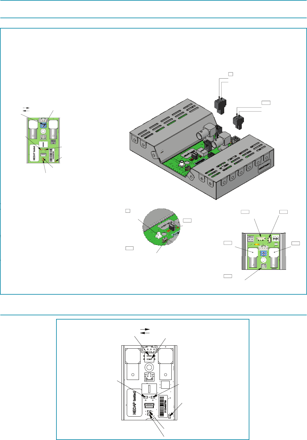
- 9 -
X2
Unit X2 Cable 2 FR + MD
A
C
-
A
YYYY-MM-DD
Documentation released
-
Ref.Nr.
REV.
DATE
DESCRIPTION
APPROVED
N/A
DIM. IN MM
ROUGHNESS ACC.
ISO 1302 in µM
GENERAL TOLERANCES
SCALE:
FORMAT:
DRAWING:
Copyright (c) by N.V. Nederlandsche Apparatenfabriek NEDAP. No part of this
drawing may be reproduced or distributed in any form or by any means, or stored
in a data base or retrieval system without the prior written permission of NEDAP.
A
B
C
D
E
F
6
3
2
5
6
7
8
A3
8017328
N/A
A.01
ARTICLE NUMBER
REV.
ISO A
GROENLO HOLLAND
SHEET:
4
7
8
5
4
3
2
10.01 OF 1
1:2
± 1°
± 0.2
DESCRIPTION
LIN.
ANG.
N/A
??
??
??
DRW:
CHCK:
YYYY-MM-DD
YYYY-MM-DD
YYYY-MM-DD
DSGN:
A
YYYY-MM-DD
Documentation released
Ref.Nr.
REV.
DATE
DESCRIPTION
APPROVED
N/A
DIM. IN MM
ROUGHNESS ACC.
ISO 1302 in µM
GENERAL TOLERANCES
SCALE:
FORMAT:
DRAWING:
Copyright (c) by N.V. Nederlandsche Apparatenfabriek NEDAP. No part of this
drawing may be reproduced or distributed in any form or by any means, or stored
in a data base or retrieval system without the prior written permission of NEDAP.
A
B
C
D
E
F
4
3
2
1
F
E
D
C
B
A
1
2
3
4
A4
8017336
N/A
A
ARTICLE NUMBER
REV.
ISO A
GROENLO HOLLAND
SHEET:
N/A
± 0.2
± 1°
1:1
10.01 OF 1
DESCRIPTION
LIN.
ANG.
DSGN:
??
??
DRW:
CHCK:
2009-MM-DD
2009-MM-DD
2009-MM-DD
??
Buzzer with cable
A
YYYY-MM-DD
Documentation released
Ref.Nr.
REV.
DATE
DESCRIPTION
APPROVED
N/A
DIM. IN MM
ROUGHNESS ACC.
ISO 1302 in µM
GENERAL TOLERANCES
SCALE:
FORMAT:
DRAWING:
Copyright (c) by N.V. Nederlandsche Apparatenfabriek NEDAP. No part of this
drawing may be reproduced or distributed in any form or by any means, or stored
in a data base or retrieval system without the prior written permission of NEDAP.
A
B
C
D
E
F
4
3
2
1
F
E
D
C
B
A
1
2
3
4
A4
4092201-rs
N/A
A
ARTICLE NUMBER
REV.
ISO A
GROENLO HOLLAND
SHEET:
N/A
± 0.2
± 1°
1:1
10.01 OF 1
DESCRIPTION
LIN.
ANG.
DSGN:
??
??
DRW:
CHCK:
2009-MM-DD
2009-MM-DD
2009-MM-DD
??
A
YYYY-MM-DD
Documentation released
Ref.Nr.
REV.
DATE
DESCRIPTION
APPROVED
N/A
DIM. IN MM
ROUGHNESS ACC.
ISO 1302 in µM
GENERAL TOLERANCES
SCALE:
FORMAT:
DRAWING:
Copyright (c) by N.V. Nederlandsche Apparatenfabriek NEDAP. No part of this
drawing may be reproduced or distributed in any form or by any means, or stored
in a data base or retrieval system without the prior written permission of NEDAP.
A
B
C
D
E
F
F
E
D
C
B
A
1
2
3
4
A4
4092201-rs
N/A
A
ARTICLE NUMBER
REV.
ISO A
GROENLO HOLLAND
SHEET:
N/A
± 0.2
± 1°
1:1
10.01 OF 1
DESCRIPTION
LIN.
ANG.
DSGN:
??
??
DRW:
CHCK:
2009-MM-DD
2009-MM-DD
2009-MM-DD
??
2x M3x10 2x M4x10
A
YYYY-MM-DD
Documentation released
Ref.Nr.
REV.
DATE
DESCRIPTION
APPROVED
N/A
DIM. IN MM
ROUGHNESS ACC.
ISO 1302 in µM
GENERAL TOLERANCES
SCALE:
FORMAT:
DRAWING:
Copyright (c) by N.V. Nederlandsche Apparatenfabriek NEDAP. No part of this
drawing may be reproduced or distributed in any form or by any means, or stored
in a data base or retrieval system without the prior written permission of NEDAP.
A
B
C
D
E
F
4
3
2
1
F
E
D
C
B
A
1
2
3
4
A4
4092201-rs
N/A
A
ARTICLE NUMBER
REV.
ISO A
GROENLO HOLLAND
SHEET:
N/A
± 0.2
± 1°
1:1
10.01 OF 1
DESCRIPTION
LIN.
ANG.
DSGN:
??
??
DRW:
CHCK:
2009-MM-DD
2009-MM-DD
2009-MM-DD
??
2x M3x6
Pin 1 = Gnd
Pin 2 = +33Volt in
K1
(YELLOW)
(Not included)
Datacom error (Red)
Power on (Green)
CC 2 (Yellow)
CC 1 (Yellow)
Alarm (Yellow)
No function (2)
50
Ω (1)
ON
OFF
Master/slave switch
Antenna
(TX-out)
USB (mini) cong port
Art.No: 7706707
NC
NC
K102
Pin 2 = - buzzer (black)
Pin 1 =
+
buzzer (red)
Sync in
Sync out
Deact. buzzer
Keyswitch
Customer
counting
K206
K3
K101
K210
SW3
K209
Keyswitch
+3V3
R474
100
Ω
GND
+3V3
IN KSW
X2 PCB
External
switchbox
SW
1
2
3
4
5
10K
Ω
Circuit diagram
K208
GND
(BLUE)
(RED)
(GREEN)
+ 12V for sensors
CC sensor 2
CC sensor 1
Gnd
K211K208
(Not included)
T5276-659
DIM. IN MM
ROUGHNESS ACC.
ISO 1302 in µM
GENERAL TOLERANCES
SCALE:
FORMAT:
DRAWING:
Copyright (c) by N.V. Nederlandsche Apparatenfabriek NEDAP. No part of this
drawing may be reproduced or distributed in any form or by any means, or stored
in a data base or retrieval system without the prior written permission of NEDAP.
6
3
2
1
F
E
D
C
B
A
5
6
7
8
A3
QUICK REFERENCE X2
5276659
c
ARTICLE NUMBER
REV.
ISO A
GROENLO HOLLAND
SHEET:
4
7
8
5
4
3
2
1
45.01 OF 2
1:1
± 1°
± 0.2
DESCRIPTION
LIN.
ANG.
N/A
CB
CB
CB
DRW:
CHCK:
2009-12-18
2009-10-26
2009-10-26
DSGN:
Pin 1 = Gnd
Pin 2 = +33Volt in
K1
(YELLOW)
(Not included)
Datacom error (Red)
Power on (Green)
CC 2 (Yellow)
CC 1 (Yellow)
Alarm (Yellow)
No function (2)
50
Ω (1)
ON
OFF
Master/slave switch
Antenna
(TX-out)
USB (mini) cong port
Art.No: 7706707
NC
NC
K102
Pin 2 = - buzzer (black)
Pin 1 =
+
buzzer (red)
Sync in
Sync out
Deact. buzzer
Keyswitch
Customer
counting
K206
K3
K101
K210
SW3
K209
Keyswitch
+3V3
R474
100
Ω
GND
+3V3
IN KSW
X2 PCB
External
switchbox
SW
1
2
3
4
5
10K
Ω
Circuit diagram
K208
GND
(BLUE)
(RED)
(GREEN)
+ 12V for sensors
CC sensor 2
CC sensor 1
Gnd
K211K208
(Not included)
T5276-659
DIM. IN MM
ROUGHNESS ACC.
ISO 1302 in µM
GENERAL TOLERANCES
SCALE:
FORMAT:
DRAWING:
Copyright (c) by N.V. Nederlandsche Apparatenfabriek NEDAP. No part of this
drawing may be reproduced or distributed in any form or by any means, or stored
in a data base or retrieval system without the prior written permission of NEDAP.
A
B
C
D
E
F
6
3
2
1
F
E
D
C
B
A
5
6
7
8
A3
QUICK REFERENCE X2
5276659
c
ARTICLE NUMBER
REV.
ISO A
GROENLO HOLLAND
SHEET:
4
7
8
5
4
3
2
1
45.01 OF 2
1:1
± 1°
± 0.2
DESCRIPTION
LIN.
ANG.
N/A
CB
CB
CB
DRW:
CHCK:
2009-12-18
2009-10-26
2009-10-26
DSGN:
Pin 1 = Gnd
Pin 2 = +33Volt in
K1
(YELLOW)
(Not included)
Datacom error (Red)
Power on (Green)
CC 2 (Yellow)
CC 1 (Yellow)
Alarm (Yellow)
No function (2)
50
Ω (1)
ON
OFF
Master/slave switch
Antenna
(TX-out)
USB (mini) cong port
Art.No: 7706707
NC
NC
K102
Pin 2 = - buzzer (black)
Pin 1 =
+
buzzer (red)
Sync in
Sync out
Deact. buzzer
Keyswitch
Customer
counting
K206
K3
K101
K210
SW3
K209
Keyswitch
+3V3
R474
100
Ω
GND
+3V3
IN KSW
X2 PCB
External
switchbox
SW
1
2
3
4
5
10K
Ω
Circuit diagram
K208
GND
(BLUE)
(RED)
(GREEN)
+ 12V for sensors
CC sensor 2
CC sensor 1
Gnd
K211K208
(Not included)
T5276-659
DIM. IN MM
ROUGHNESS ACC.
ISO 1302 in µM
GENERAL TOLERANCES
SCALE:
FORMAT:
DRAWING:
Copyright (c) by N.V. Nederlandsche Apparatenfabriek NEDAP. No part of this
drawing may be reproduced or distributed in any form or by any means, or stored
in a data base or retrieval system without the prior written permission of NEDAP.
A
B
C
D
E
F
6
3
2
1
F
E
D
C
B
A
5
6
7
8
A3
QUICK REFERENCE X2
5276659
c
ARTICLE NUMBER
REV.
ISO A
GROENLO HOLLAND
SHEET:
4
7
8
5
4
3
2
1
45.01 OF 2
1:1
± 1°
± 0.2
DESCRIPTION
LIN.
ANG.
N/A
CB
CB
CB
DRW:
CHCK:
2009-12-18
2009-10-26
2009-10-26
DSGN:
01
Pin 1 = Gnd
Pin 2 = +33Volt in
K1
(YELLOW)
(Not included)
Datacom error (Red)
Power on (Green)
CC 2 (Yellow)
CC 1 (Yellow)
Alarm (Yellow)
No function (2)
50
Ω (1)
ON
OFF
Master/slave switch
Antenna
(TX-out)
USB (mini) cong port
Pin 2 = - buzzer (black)
Pin 1 =
+
buzzer (red)
Sync in
Deact. buzzer
Keyswitch
Customer
counting
K206
K3
K101
K210
SW3
K209
Keyswitch
+3V3
R474
100
Ω
GND
+3V3
IN KSW
X2 PCB
External
switchbox
SW
1
2
3
4
5
10K
Ω
Circuit diagram
K208
GND
(BLUE)
(RED)
(GREEN)
+ 12V for sensors
CC sensor 2
CC sensor 1
Gnd
K211K208
(Not included)
DIM. IN MM
ROUGHNESS ACC.
ISO 1302 in µM
GENERAL TOLERANCES
SCALE:
FORMAT:
DRAWING:
Copyright (c) by N.V. Nederlandsche Apparatenfabriek NEDAP. No part of this
drawing may be reproduced or distributed in any form or by any means, or stored
in a data base or retrieval system without the prior written permission of NEDAP.
6
3
2
1
F
E
D
C
B
A
5
6
7
A3
QUICK REFERENCE X2
5276659
ARTICLE NUMBER
ISO A
GROENLO HOLLAND
SHEET:
4
7
5
4
3
2
1
45.01 OF 2
1:1
± 1°
± 0.2
DESCRIPTION
LIN.
ANG.
N/A
CB
CB
CB
DRW:
CHCK:
DSGN:
A
-
A
YYYY-MM-DD
Ref.Nr.
REV.
ROUGHNESS ACC.
3
2
1
4
5
Pin 1 = Gnd
Pin 2 = +33Volt in
K1
(YELLOW)
(Not included)
Datacom error (Red)
Power on (Green)
CC 2 (Yellow)
CC 1 (Yellow)
Alarm (Yellow)
No function (2)
50
Ω (1)
ON
OFF
Master/slave switch
Antenna
(TX-out)
USB (mini) cong port
Pin 2 = - buzzer (black)
Pin 1 =
+
buzzer (red)
Sync in
Deact. buzzer
Customer
counting
K206
K3
K101
K210
SW3
K209
Keyswitch
+3V3
R474
100
Ω
GND
+3V3
IN KSW
X2 PCB
External
switchbox
SW
1
2
3
4
5
10K
Ω
Circuit diagram
K208
GND
(BLUE)
(RED)
(GREEN)
+ 12V for sensors
CC sensor 2
CC sensor 1
Gnd
K208
DIM. IN MM
ROUGHNESS ACC.
ISO 1302 in µM
GENERAL TOLERANCES
SCALE:
FORMAT:
DRAWING:
Copyright (c) by N.V. Nederlandsche Apparatenfabriek NEDAP. No part of this
drawing may be reproduced or distributed in any form or by any means, or stored
in a data base or retrieval system without the prior written permission of NEDAP.
6
3
2
1
F
E
D
C
B
A
5
6
7
A3
QUICK REFERENCE X2
5276659
ARTICLE NUMBER
ISO A
GROENLO HOLLAND
SHEET:
4
7
5
4
3
2
1
1:1
± 1°
± 0.2
DESCRIPTION
LIN.
ANG.
N/A
DRW:
CHCK:
DSGN:
Pin 1 = Gnd
Pin 2 = +33Volt in
K1
(YELLOW)
(Not included)
Datacom error (Red)
Power on (Green)
CC 2 (Yellow)
CC 1 (Yellow)
Alarm (Yellow)
No function (2)
50
Ω (1)
ON
OFF
Master/slave switch
Antenna
(TX-out)
USB (mini) cong port
Pin 2 = - buzzer (black)
Pin 1 =
+
buzzer (red)
Sync in
Deact. buzzer
Keyswitch
Customer
counting
K206
K3
K101
K210
SW3
K209
Keyswitch
+3V3
R474
100
Ω
GND
+3V3
IN KSW
X2 PCB
External
switchbox
SW
1
2
3
4
5
10K
Ω
Circuit diagram
K208
GND
(BLUE)
(RED)
(GREEN)
+ 12V for sensors
CC sensor 2
CC sensor 1
Gnd
K211K208
DIM. IN MM
ROUGHNESS ACC.
ISO 1302 in µM
GENERAL TOLERANCES
SCALE:
FORMAT:
DRAWING:
Copyright (c) by N.V. Nederlandsche Apparatenfabriek NEDAP. No part of this
drawing may be reproduced or distributed in any form or by any means, or stored
in a data base or retrieval system without the prior written permission of NEDAP.
6
3
2
1
F
E
D
C
B
A
5
6
7
A3
QUICK REFERENCE X2
5276659
ARTICLE NUMBER
ISO A
GROENLO HOLLAND
SHEET:
4
7
5
4
3
2
1
1:1
± 1°
± 0.2
DESCRIPTION
LIN.
ANG.
N/A
CB
CB
CB
DRW:
CHCK:
DSGN:
Pin 1 = Gnd
Pin 2 = +33Volt in
K1
(YELLOW)
(Not included)
Master/slave switch
Antenna
(TX-out)
USB (mini) cong port
Art.No: 7706707
NC
NC
K102
Pin 2 = - buzzer (black)
Pin 1 =
+
buzzer (red)
Sync in
Sync out
Deact. buzzer
Keyswitch
Customer
counting
K206
K3
K101
K210
SW3
K209
(BLUE)
(RED)
(GREEN)
+ 12V for sensors
CC sensor 2
CC sensor 1
Gnd
K211K208
(Not included)
T5276-659
DIM. IN MM
ROUGHNESS ACC.
ISO 1302 in µM
GENERAL TOLERANCES
SCALE:
FORMAT:
DRAWING:
Copyright (c) by N.V. Nederlandsche Apparatenfabriek NEDAP. No part of this
drawing may be reproduced or distributed in any form or by any means, or stored
in a data base or retrieval system without the prior written permission of NEDAP.
A
B
C
D
E
F
6
5
6
7
8
A3
QUICK REFERENCE X2
5276659
c
ARTICLE NUMBER
REV.
ISO A
GROENLO HOLLAND
SHEET:
4
7
8
5
4
45.01 OF 2
1:1
± 1°
± 0.2
DESCRIPTION
LIN.
ANG.
N/A
CB
CB
CB
DRW:
CHCK:
2009-12-18
2009-10-26
2009-10-26
DSGN:
3. PCB Components overview
3.1 Connector overview
3.2 LED overview
Power on(Green)
CC 1(Yellow)
CC 2(Yellow)
Datacom error(Red)
Alarm(Yellow)
50
Ω (1)
ON
OFF
No function(2)

- 10 -
4. Unit address
The X2 PCB has one network address. Be sure the correct Functionality Modules are installed
5. Connection to PC / Laptop
The X2 uses a min-usb connector for a direct connection with the Conguration Manager.
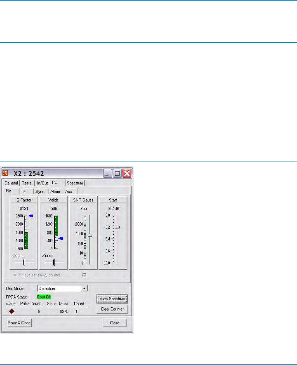
- 11 -
6.CongurationManager
All real-time data displayed in the conguration manager, is a subset from the real data. The data communication is not
showing all data, to limit the load on the data bus.
6.1 PL TAB
Below there are 4 real-time parameters, Alarm (red colored), Pulse Count, Sinus / Gauss and internal label detected
counter. The alarm is indicating that the two blue markers are simultaneous in the green area, when the label is gone this
alarm will immediately dim. The lamp on the antenna will be triggered by this signal but has a hold function. The channel and
corresponding frequency will always give a predicted value of the center frequency of the label. When there is no label, it will
predict it in the noise. This results in random changes.
The counter is an internal counter and independent from the counter used for easi/net. The counter has a reset button ‘clear’.
During switching on the unit, the FPGA on board has to be booted. The FPGA status tells if this process succeeded.
A View Spectrum button will open another window with a real-time plot of the spectrum.
The button Save & Close saves all the control parameters into a ash and closes this window. During next boot, the new
written control parameters will be loaded.
6.2 PL RX TAB
This is the main window that gives a quick overview of the
system dynamics. There are two displays showing information of the
actual Q and number of valids. In this display is a green
colored range. This gives the threshold of the receiver for
generating alarm. When both blue markers are simultaneous in
the green area an alarm will be generated. The zoom control is
centered at the max. value of the Q-factor and the min. value of
the Valids.
The control SNR is automated in case Automatic Sensitivity
Control (ASC) is allways activated. During booting of the unit, the
environment of the antenna must be clean from labels.
Start control is default set to a safe value (-3.2dB). This must be
save for almost all situations. When the installation of all units
is done and stable, you can test if the performance is ok. The
performance can be tweaked to its highest level by changing the Start
control to a lower loss value. The dB scale is indicating the expected
sensitivity performance compared to the perfect situation with a
label of Q=80. In situations of using labels with very low Q, it is
giving the most boost. High Q labels benet not so much from changing this control.
6.3 PL TX TAB
The transmitter can be switched on/off with TX On.
Temperature is monitored and the TX RF power is reduced or switched off when the temperature is above normal.
To prevent label from deactivating, a power control can be used. This control will reduce the RF power at the antenna when
a label enters in its possible deactivation level. The Power meter indicates the actual power of the RF power amplier, where
128 is max. power and 0 is min. power.
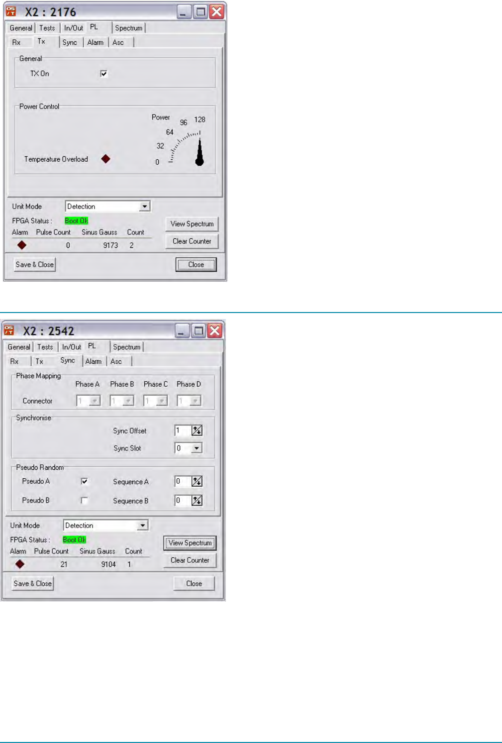
- 12 -
6.4 PL Sync TAB
When the unit is combined with other units, it needs to be
synchronized. This can be switched on/off with unit synchroni-
zation (sync). With unit sync activated, the timing of all the units
will be such that the have no/minimum interference from each
other. The sync offset must be set depending on the connection
to the NCC. When the unit is connected to the master NCC this
offset is 0. When the unit is connected to the rst slave NCC this
offset must be set to 1, the second NCC to 2, third NCC to 3 etc.
There are two sync slots 0 and 1. It is free to select a value. Between
units with a different value one is 0 and the other 1, means they are
100% independent from each other even in an environment with
very strong coupling between antennas at large distances.
Remark: When unit sync is active and no sync is connected, the
buzzer and RF signal are switched off to prevent false alarms
in this and other units. When Unit sync is activated but no sync
signal is connected, the RED LED on the unit is on (D101). So
RED LED D101 on? No RF TX signal and alarm are given.
To synchronize the Nedap Retail sweep system with the X2 we
need to set the correct active phase. When a Nedap swept system is synchronized with the X2, all mux settings on the sweep
system must be set on 4. This gives phases A,B,C and D. When the sweep system is active in phase A and B the X2 must be
switched to the other free phases C and D.
This product only supports a sweep system(s) connected to/congured as the master NCC.
In default setting, all phases are switched to active (value 1). If a swept system is congured to work on phase 1, the chameleon
must have that phase inactive so value 0. In general when synchronizing a swept system with the chameleon, the phases must
be inverted from each other.
Synchronization of Nedap sweep systems other then NCC MK2 (P2) are not supported.
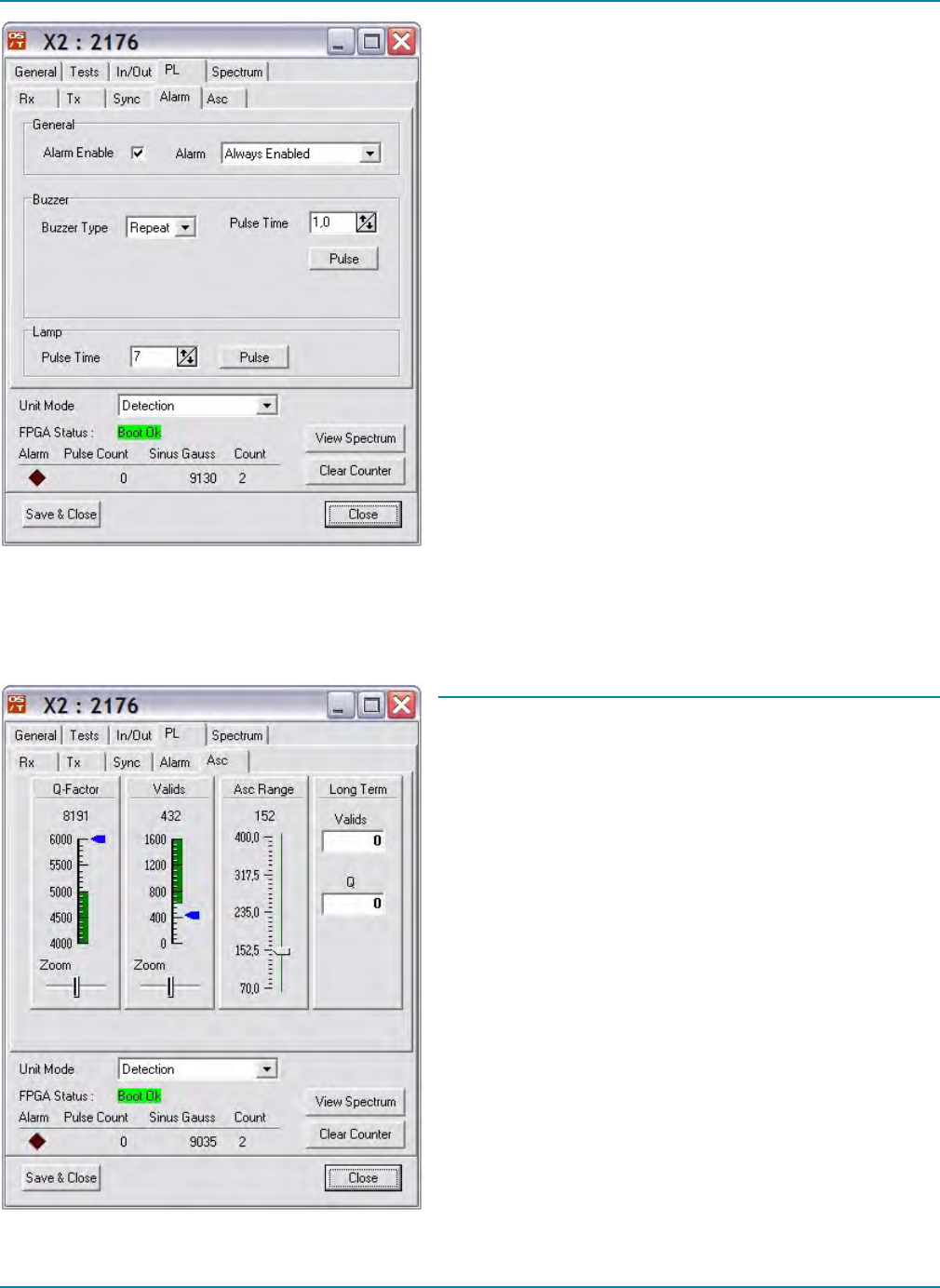
- 13 -
6.5 PL Alarm TAB
Alarm Enable is default active. When no lamp and buzzer
signal must be given it must be switched off. Remember that when
switched off, EASi/Net™ will NOT register events.
Buzzer mode: select between off, whine or continuous
Lamps Pulse mode: is the hold time of the lamp after label is not
in the detection eld
6.6 ASC
With the ASC Range, the sensitivity can be controlled. If there
is a situation that less sensitive is wanted, the ASC range can be
increased (larger number). To decrease (lower sensitive) the
detection range default ASC=100.
Long term valids and log term Q give an indication in the stability
of the unit in this environment. If both are 0 and stay 0, the unit
function stable.
6.7 Spectrum analyzer
Using View Spectrum will open an extra window with a spectrum analyser. The same window can be selected with the TAB
Spectrum.
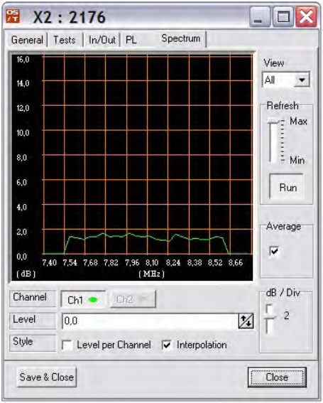
- 14 -
This is a real-time spectrum analyser. On the horizontal axe is
frequency (between 7.4MHz and 8.8MHz), and vertical is level
relative given in dB.
The Level can be changed up/down. Scaling can be changed to
zoom in and out. Average can be switched between quicker
response but more noise to slower response but les noise.
At selection View are 3 choices of view types:
• All : show everything
• Gauss: only update plot when normal noise is detected
• Valid: only update plot when normal noise is detected and the
correct signal to noise (SNR)
These 3 types give you the tools to determine what the spectral
environment looks like. Is the environment clean, is there a carrier,
is there a swept system or is there a pulse-listen system.
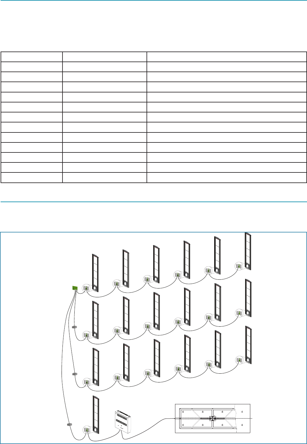
- 15 -
7.Systemconguration
The new X2 electronics can be used as an internal in an antenna or external electronics. By use of an power inserter, 6
electronics can be connected.
An NCC MK2 can communicate with up to a maximum of 24 X2 electronics.
Table 1
Number of antennas Non-connected systems Connected systems
1 - 6 1 power inserter 1 NCC
7 - 12 1 NCC, 1 Power Inserter same as non-connected, plus modem or LAN
13 - 18 1 NCC, 2 Power Inserters same as non-connected, plus modem or LAN
19 - 24 1 NCC, 3 Power Inserters same as non-connected, plus modem or LAN
25 - 30 2 NCC’s, 3 Power Inserter same as non-connected, plus modem or LAN
31 - 36 2 NCC’s, 4 Power Inserters same as non-connected, plus modem or LAN
37 - 42 2 NCC’s, 5 Power Inserters same as non-connected, plus modem or LAN
43 - 48 3 NCC’s, 5 Power Inserters same as non-connected, plus modem or LAN
49 - 54 3 NCC’s, 6 Power Inserters same as non-connected, plus modem or LAN
55 - 60 3 NCC’s, 7 Power Inserters same as non-connected, plus modem or LAN
61 - 66 4 NCC’s, 7 Power Inserters same as non-connected, plus modem or LAN
etc. etc. etc.
7.1Mediumscaleinstallationexample
When using a 4 output NCC, a maximum of 24 PCB’s can be connected. Below an example of a system with 19 antennas and
48 antennas.
NCC MK2
Power
Inserter
Power
Inserter
Power
Inserter
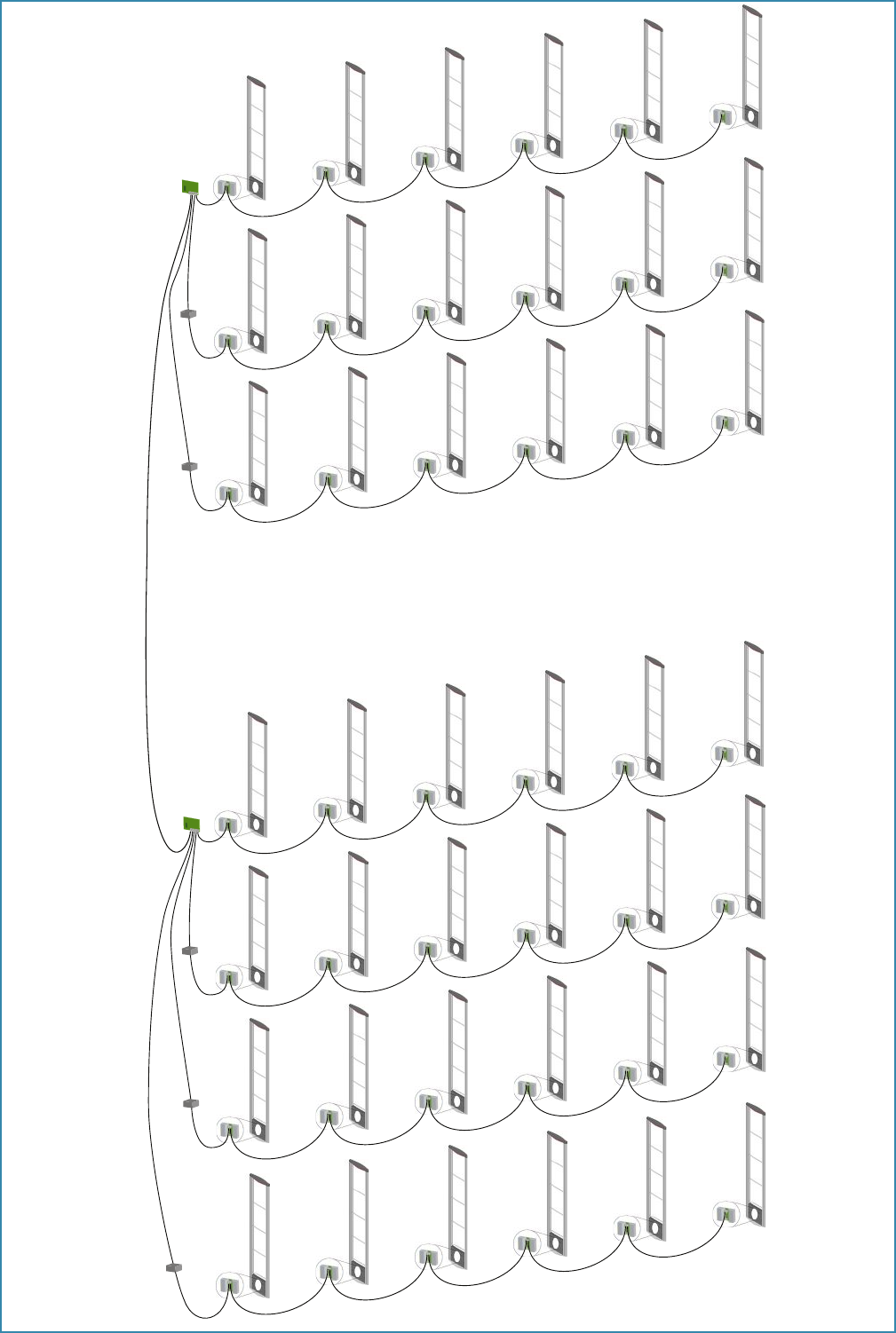
- 16 -
NCC MK2
Power
Inserter
Power
Inserter
NCC MK2
Power
Inserter
Power
Inserter
Power
Inserter

- 17 -
8.SpecicationsX2
Frequency : 8.2 MHz
Antenna Connections : 1x 50 Ohm BNC Transceiver connector
Synchronization : 1x input 50 Ohm BNC
1x output 50 Ohm BNC
Weight : 3 kg
Temperature range : 0°C …+40°C
Power Supply : 30~33V DC, 400mA
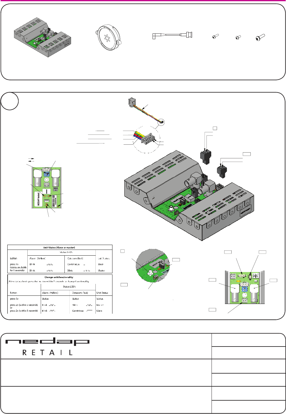
- 18 -
GROENLO - HOLLAND
Copyright © by N.V. Nederlandsche Apparatenfabriek NEDAP. No part of this drawing
may be reproduced or distributed in any form or by any means, or stored in a data base or
retrieval system without the prior written permission of NEDAP.
description:
QUICK REFERENCE X2 | art no. 8017328
doc. article no: 5276659
chk:
rev. : D
drw: CB 2011/03/09
sheet: 45.01 of 1
drawing: T5276-659
X2
Unit X2 Cable 2 FR + MD
A
C
-
A
YYYY-MM-DD
Documentation released
-
Ref.Nr.
REV.
DATE
DESCRIPTION
APPROVED
N/A
DIM. IN MM
ROUGHNESS ACC.
ISO 1302 in µM
GENERAL TOLERANCES
SCALE:
FORMAT:
DRAWING:
Copyright (c) by N.V. Nederlandsche Apparatenfabriek NEDAP. No part of this
drawing may be reproduced or distributed in any form or by any means, or stored
in a data base or retrieval system without the prior written permission of NEDAP.
A
B
C
D
E
F
6
3
2
1
F
E
D
C
B
A
5
6
7
8
A3
8017328
N/A
A.01
ARTICLE NUMBER
REV.
ISO A
GROENLO HOLLAND
SHEET:
4
7
8
5
4
3
2
1
10.01 OF 1
1:2
± 1°
± 0.2
DESCRIPTION
LIN.
ANG.
N/A
??
??
??
DRW:
CHCK:
YYYY-MM-DD
YYYY-MM-DD
YYYY-MM-DD
DSGN:
A
YYYY-MM-DD
Documentation released
Ref.Nr.
REV.
DATE
DESCRIPTION
APPROVED
N/A
DIM. IN MM
ROUGHNESS ACC.
ISO 1302 in µM
GENERAL TOLERANCES
SCALE:
FORMAT:
DRAWING:
Copyright (c) by N.V. Nederlandsche Apparatenfabriek NEDAP. No part of this
drawing may be reproduced or distributed in any form or by any means, or stored
in a data base or retrieval system without the prior written permission of NEDAP.
A
B
C
D
E
F
4
3
2
1
F
E
D
C
B
A
1
2
3
4
A4
8017336
N/A
A
ARTICLE NUMBER
REV.
ISO A
GROENLO HOLLAND
SHEET:
N/A
± 0.2
± 1°
1:1
10.01 OF 1
DESCRIPTION
LIN.
ANG.
DSGN:
??
??
DRW:
CHCK:
2009-MM-DD
2009-MM-DD
2009-MM-DD
??
Buzzer with cable
A
YYYY-MM-DD
Documentation released
Ref.Nr.
REV.
DATE
DESCRIPTION
APPROVED
N/A
DIM. IN MM
ROUGHNESS ACC.
ISO 1302 in µM
GENERAL TOLERANCES
SCALE:
FORMAT:
DRAWING:
Copyright (c) by N.V. Nederlandsche Apparatenfabriek NEDAP. No part of this
drawing may be reproduced or distributed in any form or by any means, or stored
in a data base or retrieval system without the prior written permission of NEDAP.
A
B
C
D
E
F
4
3
2
1
F
E
D
C
B
A
1
2
3
4
A4
4092201-rs
N/A
A
ARTICLE NUMBER
REV.
ISO A
GROENLO HOLLAND
SHEET:
N/A
± 0.2
± 1°
1:1
10.01 OF 1
DESCRIPTION
LIN.
ANG.
DSGN:
??
??
DRW:
CHCK:
2009-MM-DD
2009-MM-DD
2009-MM-DD
??
A
YYYY-MM-DD
Documentation released
Ref.Nr.
REV.
DATE
DESCRIPTION
APPROVED
N/A
DIM. IN MM
ROUGHNESS ACC.
ISO 1302 in µM
GENERAL TOLERANCES
SCALE:
FORMAT:
DRAWING:
Copyright (c) by N.V. Nederlandsche Apparatenfabriek NEDAP. No part of this
drawing may be reproduced or distributed in any form or by any means, or stored
in a data base or retrieval system without the prior written permission of NEDAP.
A
B
C
D
E
F
4
3
2
1
F
E
D
C
B
A
1
2
3
4
A4
4092201-rs
N/A
A
ARTICLE NUMBER
REV.
ISO A
GROENLO HOLLAND
SHEET:
N/A
± 0.2
± 1°
1:1
10.01 OF 1
DESCRIPTION
LIN.
ANG.
DSGN:
??
??
DRW:
CHCK:
2009-MM-DD
2009-MM-DD
2009-MM-DD
??
2x M3x10 2x M4x10
A
YYYY-MM-DD
Documentation released
Ref.Nr.
REV.
DATE
DESCRIPTION
APPROVED
N/A
DIM. IN MM
ROUGHNESS ACC.
ISO 1302 in µM
GENERAL TOLERANCES
SCALE:
FORMAT:
DRAWING:
Copyright (c) by N.V. Nederlandsche Apparatenfabriek NEDAP. No part of this
drawing may be reproduced or distributed in any form or by any means, or stored
in a data base or retrieval system without the prior written permission of NEDAP.
A
B
C
D
E
F
4
3
2
1
F
E
D
C
B
A
1
2
3
4
A4
4092201-rs
N/A
A
ARTICLE NUMBER
REV.
ISO A
GROENLO HOLLAND
SHEET:
N/A
± 0.2
± 1°
1:1
10.01 OF 1
DESCRIPTION
LIN.
ANG.
DSGN:
??
??
DRW:
CHCK:
2009-MM-DD
2009-MM-DD
2009-MM-DD
??
2x M3x6
Pin 1 = Gnd
Pin 2 = +33Volt in
K1
(YELLOW)
(Not included)
Datacom error (Red)
Power on (Green)
CC 2 (Yellow)
CC 1 (Yellow)
Alarm (Yellow)
No function (2)
50
Ω (1)
ON
OFF
Master/slave switch
Antenna
(TX-out)
USB (mini) config port
Art.No: 7706707
NC
NC
K102
Pin 2 = - buzzer (black)
Pin 1 =
+
buzzer (red)
Sync in
Sync out
Deact. buzzer
Keyswitch
Customer
counting
K206
K3
K101
K210
SW3
K209
Keyswitch
+3V3
R474
100
Ω
GND
+3V3
IN KSW
X2 PCB
External
switchbox
SW
1
2
3
4
5
10K
Ω
Circuit diagram
K208
GND
(BLUE)
(RED)
(GREEN)
+ 12V for sensors
CC sensor 2
CC sensor 1
Gnd
K211K208
(Not included)
T5276-659
DIM. IN MM
ROUGHNESS ACC.
ISO 1302 in µM
GENERAL TOLERANCES
SCALE:
FORMAT:
DRAWING:
Copyright (c) by N.V. Nederlandsche Apparatenfabriek NEDAP. No part of this
drawing may be reproduced or distributed in any form or by any means, or stored
in a data base or retrieval system without the prior written permission of NEDAP.
A
B
C
D
E
F
6
3
2
1
F
E
D
C
B
A
5
6
7
8
A3
QUICK REFERENCE X2
5276659
c
ARTICLE NUMBER
REV.
ISO A
GROENLO HOLLAND
SHEET:
4
7
8
5
4
3
2
1
45.01 OF 2
1:1
± 1°
± 0.2
DESCRIPTION
LIN.
ANG.
N/A
CB
CB
CB
DRW:
CHCK:
2009-12-18
2009-10-26
2009-10-26
DSGN:
Pin 1 = Gnd
Pin 2 = +33Volt in
K1
(YELLOW)
(Not included)
Datacom error (Red)
Power on (Green)
CC 2 (Yellow)
CC 1 (Yellow)
Alarm (Yellow)
No function (2)
50
Ω (1)
ON
OFF
Master/slave switch
Antenna
(TX-out)
USB (mini) config port
Art.No: 7706707
NC
NC
K102
Pin 2 = - buzzer (black)
Pin 1 =
+
buzzer (red)
Sync in
Sync out
Deact. buzzer
KeyswitchCustomer
counting
K206
K3
K101
K210
SW3
K209
Keyswitch
+3V3
R474
100
Ω
GND
+3V3
IN KSW
X2 PCB
External
switchbox
SW
1
2
3
4
5
10K
Ω
Circuit diagram
K208
GND
(BLUE)
(RED)
(GREEN)
+ 12V for sensors
CC sensor 2
CC sensor 1
Gnd
K211K208
(Not included)
T5276-659
DIM. IN MM
ROUGHNESS ACC.
ISO 1302 in µM
GENERAL TOLERANCES
SCALE:
FORMAT:
DRAWING:
Copyright (c) by N.V. Nederlandsche Apparatenfabriek NEDAP. No part of this
drawing may be reproduced or distributed in any form or by any means, or stored
in a data base or retrieval system without the prior written permission of NEDAP.
A
B
C
D
E
F
6
3
2
1
F
E
D
C
B
A
5
6
7
8
A3
QUICK REFERENCE X2
5276659
c
ARTICLE NUMBER
REV.
ISO A
GROENLO HOLLAND
SHEET:
4
7
8
5
4
3
2
1
45.01 OF 2
1:1
± 1°
± 0.2
DESCRIPTION
LIN.
ANG.
N/A
CB
CB
CB
DRW:
CHCK:
2009-12-18
2009-10-26
2009-10-26
DSGN:
Pin 1 = Gnd
Pin 2 = +33Volt in
K1
(YELLOW)
(Not included)
Datacom error (Red)
Power on (Green)
CC 2 (Yellow)
CC 1 (Yellow)
Alarm (Yellow)
No function (2)
50
Ω (1)
ON
OFF
Master/slave switch
Antenna
(TX-out)
USB (mini) config port
Art.No: 7706707
NC
NC
K102
Pin 2 = - buzzer (black)
Pin 1 =
+
buzzer (red)
Sync in
Sync out
Deact. buzzer
Keyswitch
Customer
counting
K206
K3
K101
K210
SW3
K209
Keyswitch
+3V3
R474
100
Ω
GND
+3V3
IN KSW
X2 PCB
External
switchbox
SW
1
2
3
4
5
10K
Ω
Circuit diagram
K208
GND
(BLUE)
(RED)
(GREEN)
+ 12V for sensors
CC sensor 2
CC sensor 1
Gnd
K211K208
(Not included)
T5276-659
DIM. IN MM
ROUGHNESS ACC.
ISO 1302 in µM
GENERAL TOLERANCES
SCALE:
FORMAT:
DRAWING:
Copyright (c) by N.V. Nederlandsche Apparatenfabriek NEDAP. No part of this
drawing may be reproduced or distributed in any form or by any means, or stored
in a data base or retrieval system without the prior written permission of NEDAP.
A
B
C
D
E
F
6
3
2
1
F
E
D
C
B
A
5
6
7
8
A3
QUICK REFERENCE X2
5276659
c
ARTICLE NUMBER
REV.
ISO A
GROENLO HOLLAND
SHEET:
4
7
8
5
4
3
2
1
45.01 OF 2
1:1
± 1°
± 0.2
DESCRIPTION
LIN.
ANG.
N/A
CB
CB
CB
DRW:
CHCK:
2009-12-18
2009-10-26
2009-10-26
DSGN:
01
Pin 1 = Gnd
Pin 2 = +33Volt in
K1
(YELLOW)
(Not included)
Datacom error (Red)
Power on (Green)
CC 2 (Yellow)
CC 1 (Yellow)
Alarm (Yellow)
No function (2)
50
Ω (1)
ON
OFF
Master/slave switch
Antenna
(TX-out)
USB (mini) config port
Art.No: 7706707
NC
NC
K102
Pin 2 = - buzzer (black)
Pin 1 =
+
buzzer (red)
Sync in
Sync out
Deact. buzzer
Keyswitch
Customer
counting
K206
K3
K101
K210
SW3
K209
Keyswitch
+3V3
R474
100
Ω
GND
+3V3
IN KSW
X2 PCB
External
switchbox
SW
1
2
3
4
5
10K
Ω
Circuit diagram
K208
GND
(BLUE)
(RED)
(GREEN)
+ 12V for sensors
CC sensor 2
CC sensor 1
Gnd
K211K208
(Not included)
T5276-659
DIM. IN MM
ROUGHNESS ACC.
ISO 1302 in µM
GENERAL TOLERANCES
SCALE:
FORMAT:
DRAWING:
Copyright (c) by N.V. Nederlandsche Apparatenfabriek NEDAP. No part of this
drawing may be reproduced or distributed in any form or by any means, or stored
in a data base or retrieval system without the prior written permission of NEDAP.
A
B
C
D
E
F
6
3
2
1
F
E
D
C
B
A
5
6
7
8
A3
QUICK REFERENCE X2
5276659
c
ARTICLE NUMBER
REV.
ISO A
GROENLO HOLLAND
SHEET:
4
7
8
5
4
3
2
1
45.01 OF 2
1:1
± 1°
± 0.2
DESCRIPTION
LIN.
ANG.
N/A
CB
CB
CB
DRW:
CHCK:
2009-12-18
2009-10-26
2009-10-26
DSGN:
A
C
-
A
YYYY-MM-DD
Documentation released
-
Ref.Nr.
REV.
DATE
DESCRIPTION
APPROVED
N/A
DIM. IN MM
ROUGHNESS ACC.
ISO 1302 in µM
GENERAL TOLERANCES
SCALE:
FORMAT:
DRAWING:
Copyright (c) by N.V. Nederlandsche Apparatenfabriek NEDAP. No part of this
drawing may be reproduced or distributed in any form or by any means, or stored
in a data base or retrieval system without the prior written permission of NEDAP.
A
B
C
D
E
F
6
3
2
1
F
E
D
C
B
A
5
6
7
8
A3
8017328
N/A
A.01
ARTICLE NUMBER
REV.
ISO A
GROENLO HOLLAND
SHEET:
4
7
8
5
4
3
2
1
10.01 OF 1
1:2
± 1°
± 0.2
DESCRIPTION
LIN.
ANG.
N/A
??
??
??
DRW:
CHCK:
YYYY-MM-DD
YYYY-MM-DD
YYYY-MM-DD
DSGN:
Pin 1 = Gnd
Pin 2 = +33Volt in
K1
(YELLOW)
(Not included)
Datacom error (Red)
Power on (Green)
CC 2 (Yellow)
CC 1 (Yellow)
Alarm (Yellow)
No function (2)
50
Ω (1)
ON
OFF
Master/slave switch
Antenna
(TX-out)
USB (mini) config port
Art.No: 7706707
NC
NC
K102
Pin 2 = - buzzer (black)
Pin 1 =
+
buzzer (red)
Sync in
Sync out
Deact. buzzer
Keyswitch
Customer
counting
K206
K3
K101
K210
SW3
K209
Keyswitch
+3V3
R474
100
Ω
GND
+3V3
IN KSW
X2 PCB
External
switchbox
SW
1
2
3
4
5
10K
Ω
Circuit diagram
K208
GND
(BLUE)
(RED)
(GREEN)
+ 12V for sensors
CC sensor 2
CC sensor 1
Gnd
K211K208
(Not included)
T5276-659
DIM. IN MM
ROUGHNESS ACC.
ISO 1302 in µM
GENERAL TOLERANCES
SCALE:
FORMAT:
DRAWING:
Copyright (c) by N.V. Nederlandsche Apparatenfabriek NEDAP. No part of this
drawing may be reproduced or distributed in any form or by any means, or stored
in a data base or retrieval system without the prior written permission of NEDAP.
A
B
C
D
E
F
6
3
2
1
F
E
D
C
B
A
5
6
7
8
A3
QUICK REFERENCE X2
5276659
c
ARTICLE NUMBER
REV.
ISO A
GROENLO HOLLAND
SHEET:
4
7
8
5
4
3
2
1
45.01 OF 2
1:1
± 1°
± 0.2
DESCRIPTION
LIN.
ANG.
N/A
CB
CB
CB
DRW:
CHCK:
2009-12-18
2009-10-26
2009-10-26
DSGN:
- 19 -
- 20 -
parallelweg 2d 7141 dc groenlo the netherlands t +31 (0) 544 47 15 55 f +31 (0) 544 46 58 14
e info-rs@nedap.com www.nedapretail.com
BACK Manual X2 2012