NetComm Wireless NTC3000 M2M SERIAL MODEM User Manual USERS MANUAL
NetComm Wireless Limited M2M SERIAL MODEM USERS MANUAL
UserManual.wiki
>
NetComm Wireless
>
NTC3000 User Manual
USERS MANUAL
Navigation menu
Upload a User Manual
Namespaces
Wiki Guide
HTML
PDF
Info
Views
User Manual
Discussion / Help
Navigation

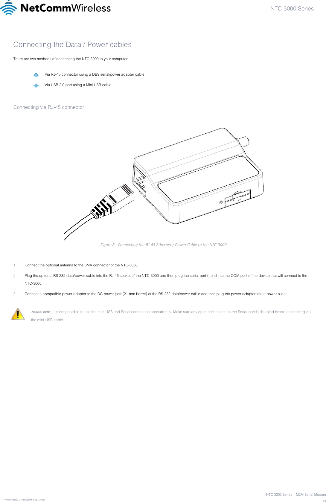

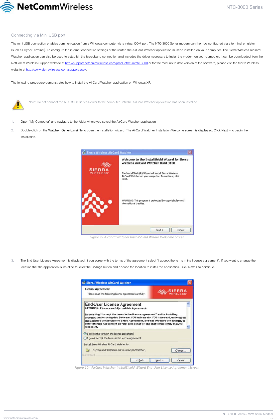
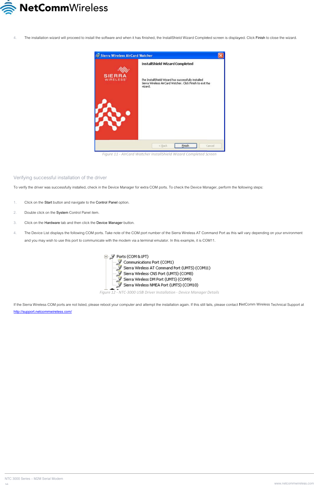

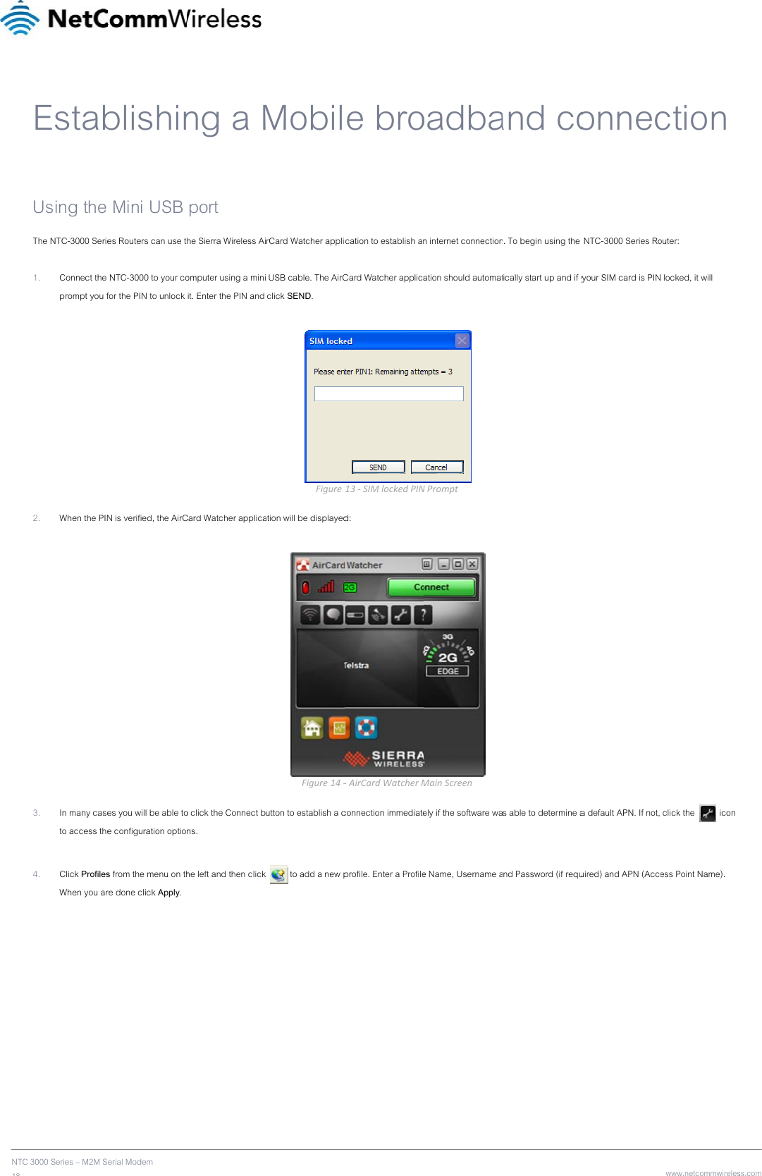
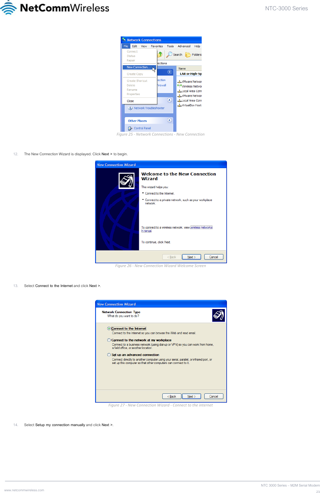
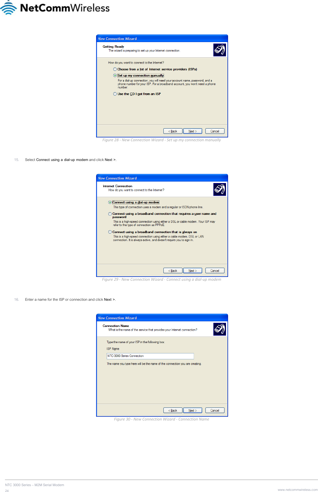
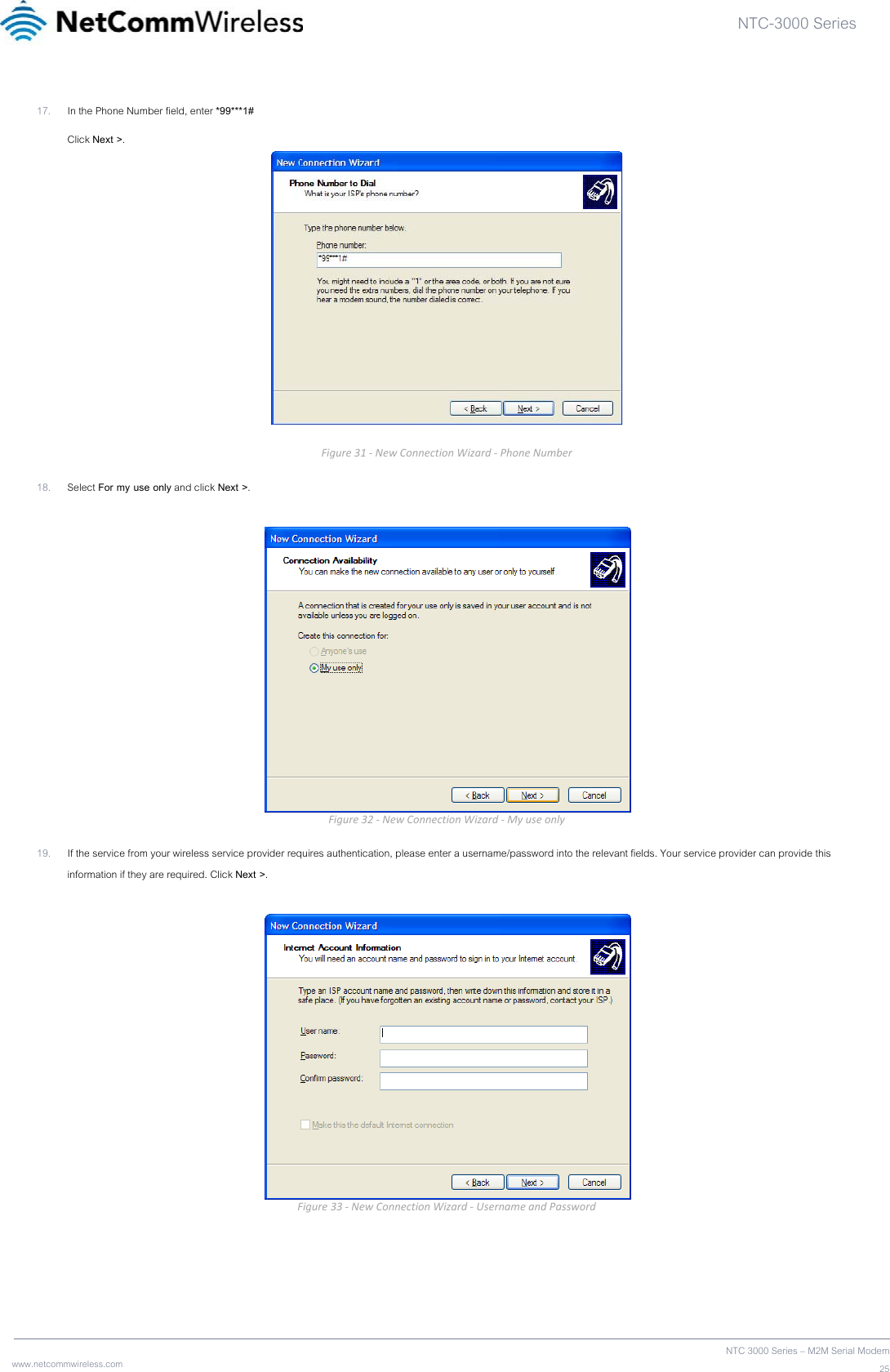
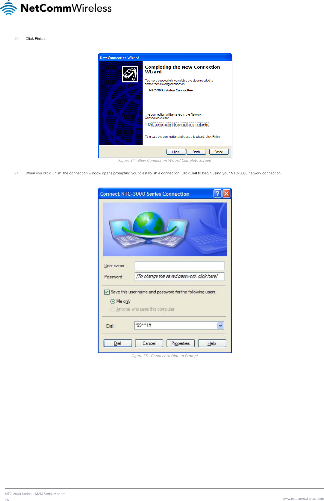
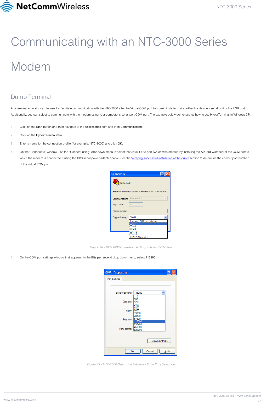
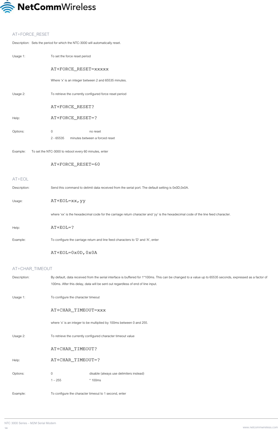
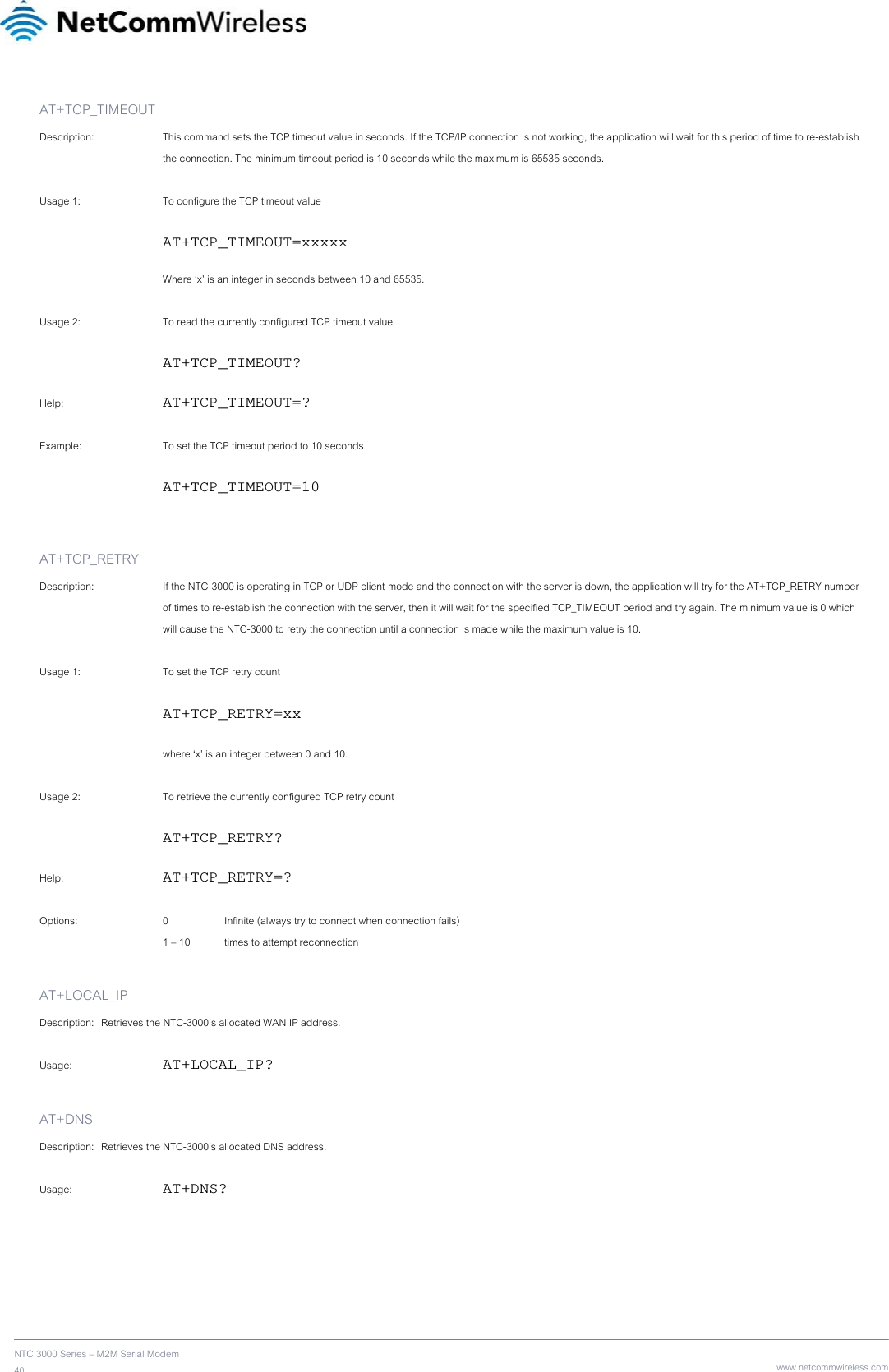
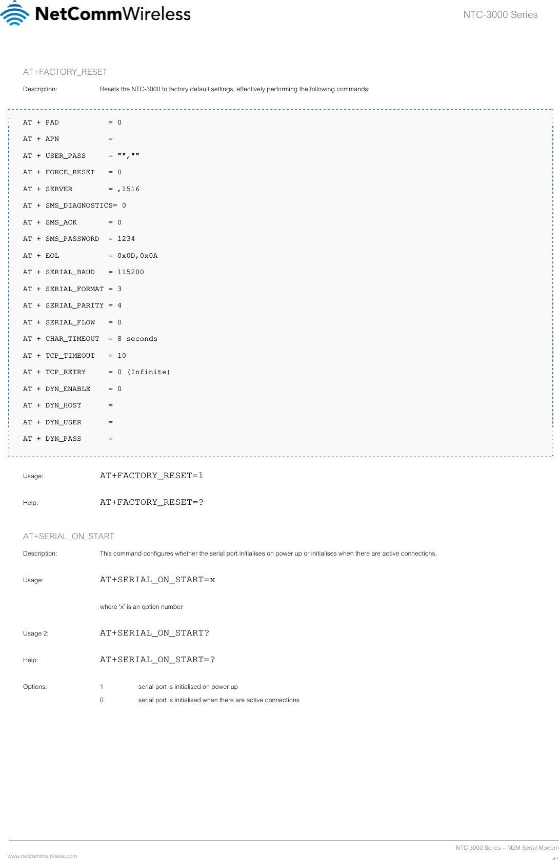
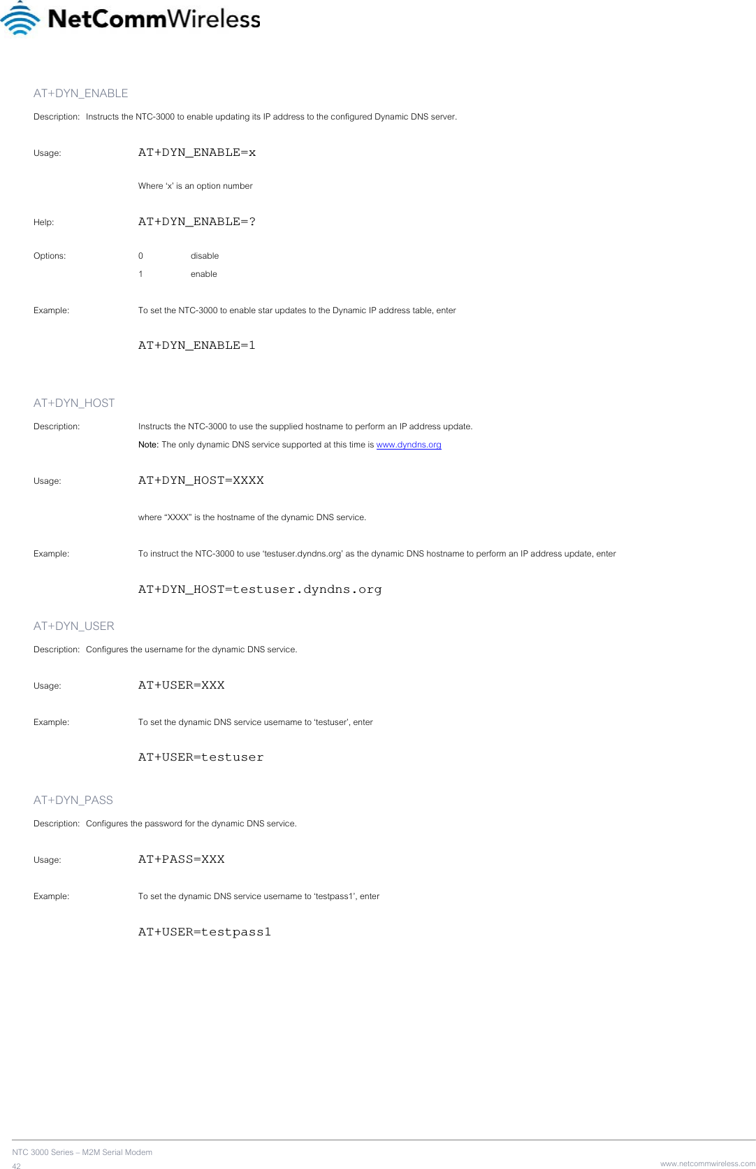
![NTC-3000 Series www.netcommwireless.com NTC 3000 Series – M2M Serial Modem31AT+APN Description: Sets the Access Point Name (APN) used to connect to the broadband network. The default setting is blank. Usage 1: To set the APN AT+APN=xxxx where ‘xxxx’ is the APN that you wish to use. Usage 2: To retrieve the currently configured APN AT+APN? Example: To set the APN to ‘testAPN’ enter AT+APN=testAPN AT+USER_PASS Description: Sets the username and password used to connect to the broadband network. Usage 1: To set the username and password AT+USER_PASS=”xxxx”,”xxxx” Usage 2: To retrieve the currently configured username and password AT+USER_PASS? Help: AT+USER_PASS=? Options: username the user name for the broadband account password the password for the broadband account Example: To configure the username as ‘user1’ and password as ‘testpass’ enter AT+USER_PASS=”user1”,”testpass” AT+SERIAL_BAUD Description: Sets the baud rate used for communication between the modem and the connected device. Usage 1: To set the baud rate AT+SERIAL_BAUD=[baud] Usage 2: To retrieve the currently configured baud rate AT+SERIAL_BAUD? Help: AT+SERIAL_BAUD=? Options: 300, 600, 1200. 2400. 4800, 9600, 19200, 38400, 57600, 115200 (default value), 230400, 460800, 921600. Example: To configure the baud rate to 115200bps enter AT+SERIAL_BAUD=115200](https://usermanual.wiki/NetComm-Wireless/NTC3000/User-Guide-2184497-Page-31.png)