NetComm Wireless NTC3000 M2M SERIAL MODEM User Manual USERS MANUAL
NetComm Wireless Limited M2M SERIAL MODEM USERS MANUAL
USERS MANUAL
N
N
TC-30
0
U
0
0 Seri
e
se
r
s – M2
M
r
Gu
M
Serial
ide
Modem
NTC
2
3000 Series – M2M S
Copyright
Copyright©2013 N
e
The information co
n
without prior writte
n
Please
n
Save Our Env
i
When this equipme
The cardboard box
dispose of this ele
c
municipal governm
e
Please be responsi
This manual c
NetComm NTC-30
0
NetComm NTC-30
0
NetComm NTC-30
0
1.0 - Initial docu
m
1.1 - Updated la
y
1.2 - Added Net
C
erial Modem
e
tComm Wireless Li
m
n
tained herein is pro
p
n
consent of NetCom
m
n
ote: This document
ironment
nt has reached the
e
x
, the plastic contain
e
c
tronic equipment al
o
ent.
ble and protect our
e
overs the follo
w
0
0-01
0
0-02
0
0-03
m
ent release
y
out of Hardware Ins
C
omm Wireless Ope
n
m
ited.
A
ll rights reser
v
p
rietary to NetComm
m
Wireless Limited.
is subject to change
e
nd of its useful life, i
t
e
d in the packaging,
o
ng with your househ
e
nvironment.
w
ing products:
tallation and Establi
s
n
AT Custom Applica
t
v
ed.
Wireless Limited. N
o
without notice.
t
must be taken to a
r
and the parts that m
a
old waste. You may
b
DOCUMEN
T
s
hing a Mobile broad
t
ion section based o
n
o
part of this docum
e
r
ecycling centre and
a
ke up this device c
a
be subject to penalti
e
T
VERSION
band connection se
c
n
software version 1.
e
nt may be translate
d
processed separat
e
a
n be recycled in ac
c
e
s or sanctions und
e
c
tions. Updated des
c
0.13
, transcribed, repro
d
e
ly from domestic wa
s
c
ordance with regio
n
e
r the law. Instead, a
s
c
riptions of interface
s
d
uced, in any form, o
ste.
n
ally established reg
u
s
k for disposal instru
c
s
.
www.netcommwirele
s
r by any means
u
lations. Never
c
tions from your
DATE
26/04/2013
24/06/2013
12/09/2013
s
s.com

NTC-3000 Series
www.netcommwireless.com
NTC 3000 Series –
M2M
Serial Modem
3
1.3 – Corrected RJ-45 to DB9 Serial/Power Adapter Cable diagram 27/11/2013
Table1‐DocumentRevisionHistory

NTC 3000 Series – M2M Serial Modem
4 www.netcommwireless.com
Table of Contents
Overview ............................................................................................................................................. 5
Saf et y and Product Care . ... . .. . ... . .. . ... . .. . ... . .. . ... . .. . .. . ... . .. . ... . .. . ... . .. . ... . .. . ... . .. . ... . .. . ... . .. . ... . .. . ... . .. . . .................... 6
Product Int roduct ion .. .. . ... . .. . ... . .. . ... . .. . ... . .. . ... . .. . ... . .. . ... . .. . ... . .. . ... . .. . ... . .. . ... . .. . ... . .. . ... . .. . .. . ... . .. . ..................... 7
Physical Dimensions and Indicators ............................................................................................................. 8
LED Indicators ........................................................................................................................................................................................................................................................................... 8
Physical Dimensions .................................................................................................................................................................................................................................................................. 8
Interfaces ............................................................................................................................................ 9
Hardware Inst allat ion .. ... . .. . ... . .. . ... . .. . ... . .. . ... . .. . ... . .. . ... . .. . ... . .. . ... . .. . .. . ... . .. . ... . .. . ... . .. . ... . .. . ... . .. . .. . .. . ... . .. . .. . ... . . 10
Inserting the SIM card ............................................................................................................................................................................................................................................................. 10
Mounting the device ................................................................................................................................................................................................................................................................ 11
Connecting the Data / Power cables ...................................................................................................................................................................................................................................... 13
Est ablishing a Mobile broadband connection ..................................................................................... . ... . .. . ... . 18
Using the Mini USB port .......................................................................................................................................................................................................................................................... 18
Using the RJ-45 connector ...................................................................................................................................................................................................................................................... 20
Communicat ing wit h an NTC-3000 Series Modem ... . .. . ... . .. . ... . .. . ... . .. . ... . .. . .. . ... . .. . ... . .. . ... . .. . ... . .. . ... . .. . ... . .. . ... . .. . ... . 27
Dumb Terminal ........................................................................................................................................................................................................................................................................ 27
Open AT Application Framework ............................................................................................................................................................................................................................................ 29
Net Comm Wireless Open AT Cust om Applicat ion ... . .. . ... . .. . ... . .. . .. . ... . .. . ... . .. . ... . .. . ... . .. . ... . .. . ... . .. . ... . .. . ... . .. . ... . . .. . ... . 30
Command List ......................................................................................................................................................................................................................................................................... 30
General Operation ................................................................................................................................................................................................................................................................... 43
Technical Data .................................................................................................................................... 48
Mini USB Connector ................................................................................................................................................................................................................................................................ 48
RJ-45 Connector ...................................................................................................................................................................................................................................................................... 49
RJ-45 to DB9 Serial/Power Adapter Cable ............................................................................................................................................................................................................................. 49
Electrical Specifications .......................................................................................................................................................................................................................................................... 50
Environmental Specifications / Tolerances ............................................................................................................................................................................................................................. 50
Product Service and Support ... . .. . ... . .. . ... . .. . ... . .. . .. . ... . .. . ... . .. . ... . .. . ... . .. . ... . .. . ... . .. . ... . .. . ... . .. . ... . .. . ... . . ... . .. . ... . .. . ... 51
Troubleshooting ....................................................................................................................................................................................................................................................................... 51
Web Based Product References ............................................................................................................................................................................................................................................. 52
FAQs ........................................................................................................................................................................................................................................................................................ 52
Appendix A: Tables .. . ... . .. . ... . .. . ... . .. . ... . .. . ... . .. . ... . .. . ... . .. . ... . .. . ... ... . .. . ... . .. . ... . .. . ... . .. . ... . .. . ... . .. . ... . . . .. . .. . ... . .. . ... . 53
Legal and Regulat ory . ... . .. . ... . .. . ... . .. . ... . .. . .. . ... . .. . ... . .. . ... . .. . ... . .. . ... . .. . ... . .. . ... . .. . ... . .. . ... . .. . ... . .. . ... . . . .. . ... . .. . ... . .. . 54

www
.netcommwireless.com
Ove
r
Introducti
o
This document det
a
Target U
s
This document is e
x
understanding of s
e
Prerequis
A computer with a
t
configuration has b
Notation
The following symb
The following note
r
The following note
p
The following note
p
r
view
o
n
a
ils the process of c
o
s
ers
x
pected to be utilise
d
e
rial based technolo
g
ites
t
erminal emulation p
r
een completed.
ols are used in this
m
r
equires attention
p
rovides a warning
p
rovides relevant inf
o
o
nfiguring the NTC-3
0
d
by system integrat
o
g
ies such as dialup
m
r
ogram (such as Hy
p
m
anual:
o
rmation.
0
00 Series device vi
a
o
rs or experienced h
a
m
odems, AT comma
n
erTerminal), a serial
a
a terminal emulatio
ardware installers w
h
n
ds and legacy data
port, an appropriate
n
program (such as
H
h
o are comfortable
w
collection devices.
power supply and a
H
yperTerminal) as w
e
ith all aspects of IP
b
device to connect t
o
NT
C
NTC 30
0
ell as mounting and
d
b
ased networking an
o
the NTC-3000 Seri
e
C
-3000 Serie
s
0 Series –
M2M
Serial
d
eployment advice.
d possess an
e
s modem after
s
Modem
5

NTC
6
3000 Series – M2M S
Safe
t
The NTC-3000 seri
e
With reference to t
h
I
D
D
o
A
E
U
WARNING:
Disconnect the po
w
Transport
When transporting
t
In the
erial Modem
t
y an
d
e
s offers a hardened
h
e unpacking, install
a
Installation, configur
a
D
o not use or install
t
D
o not use or install
t
o
perating temperatu
r
A
rrange any cables i
E
nsure that the volta
g
U
se only a clean, dr
y
w
er line from the devi
and Han
d
t
he NTC-3000 Serie
s
event the product n
e
d
Pro
d
industrial enclosure
a
tion, use and maint
e
a
tion and disassemb
t
his product near wa
t
his product in extre
m
r
e range (-40°C to 8
5
n a manner such th
a
g
e and rated curren
t
y
cloth to wipe the d
e
ce before servicing.
d
ling
s
, it is recommended
e
eds to be returned,
e
d
uct
C
making it suitable fo
r
e
nance of your electr
o
ly should be perfor
m
t
er to avoid fire or sh
m
ely hot or cold area
5
°C).
a
t they are not likely t
o
of the power source
e
vice. Never apply c
h
to return the produc
t
e
nsure it is securely
C
are
r a variety of remote
r
onic device, the foll
o
m
ed by trained perso
n
ock hazard.
A
void e
x
a
s. Ensure that the d
e
o
be stepped on or
h
e
match the requirem
h
emical cleaners on
t
t
to the original pack
a
packaged with appr
o
deployment location
o
wing basic guidelin
e
n
nel only.
x
posing the equipm
e
e
vice is installed in a
n
h
ave items placed o
n
ents of the device.
D
t
he device.
a
ging. This ensures
t
o
priate padding to p
s
.
e
s are recommended
e
nt to rain or damp a
r
n
area where the tem
them.
o not connect the d
e
t
he product will not
b
r
event damage durin
d
:
r
eas.
m
perature is within th
e
e
vice to an inapprop
r
b
e damaged.
n
g courier transport.
www.netcommwirele
s
e
supported
r
iate power source.
s
s.com

NTC-3000 Series
www.netcommwireless.com
NTC 3000 Series –
M2M
Serial Modem
7
Product Introduction
Product Overview
Small-sized and rugged industrial-grade 3G modem for wireless data communication
Provides reliable RS232 serial data connectivity for various M2M applications
Supports standard AT command set
Supports various networks and service types UMTS/HSDPA/HSUPA & GSM/GPRS/EDGE
Embedded Internet and security protocol stacks
Wide input voltage range 5-36V DC suitable for diverse environments and applications
RS232 serial data connection and power input via RJ45 port
USB 2.0 port for communicating (e.g. Dial-up networking from Windows PC and Mac)
Supports Open AT and AirVantage
DIN rail and wall mount option with removable mounting bracket
SIM card reader with locking tray
Wide operating temperature range -40 to 85°C
Package Contents
The NTC-3000 series package consists of:
NTC-3000 Series Modem
Quick Start Guide
The following items are available as optional accessories:
External antenna
DB9 serial/power adapter cable
Mounting bracket
If any of these items are missing or damaged, please contact NetComm Support immediately by visiting the NetComm Support website at: http://support.netcommwireless.com/ .
Product Features
The NTC-3000 Series is a reliable solution for cost effective deployment in any data telemetry environment. Designed for reliable performance and universal installation it provides 3G
data connectivity for M2M applications enabling remote monitoring, control, management and reporting of industrial and commercial equipment.
The small and rugged form factor is ideal for applications such as metering, rail, road signs, security, transport and vending machines. It can also be used in SCADA (Supervisory
Control and Data Acquisition) scenarios to monitor, control or collect data from remote devices such as farm machinery, water monitoring devices and wind farms.
A serial connection on one end and a 3G connection on the other allows the devices to simply take the serial data and send it over 3G. When connecting through the RJ-45 port to the
serial port of your device, the broadband connection can be established using AT commands in a terminal emulator or through the use of a Windows Dial Up Networking profile. The
modem also comes equipped with a Mini USB port where a connection can be established through either a virtual COM port or Sierra Wireless’s AirCard Watcher application.
The lockable SIM tray along with the rugged nature of the device means you can be assured that your device is working reliably, regardless of the physical location.
NTC 3000 Series – M2M Serial Modem
8 www.netcommwireless.com
Physical Dimensions and Indicators
LED Indicators
The NTC-3000 Series uses two LEDs to display the current system and connection status.
LED INDICATOR COLOUR DEFINITION
Power
Off The Power is off.
Red The Power is on and the NTC-3000 is operating normally.
3G
Off The NTC-3000 is not connected to a 3G network.
Slow flashing green The NTC-3000 is attempting to connect to a 3G network.
Quick flashing green Data is moving across the 3G connection.
Table2‐LEDIndicators
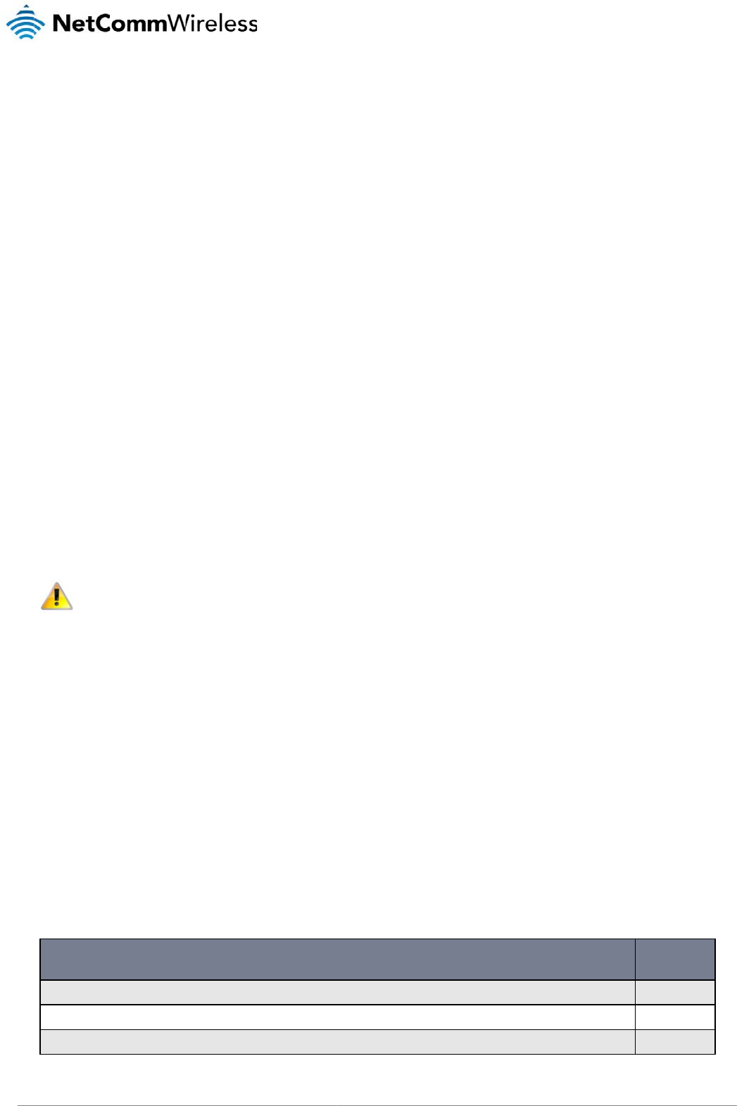
Physical Dimensions
The following page lists the physical dimensions of the NTC-3000 Series as well as the physical dimensions of the mounting bracket which can be used to attach the NTC-3000 Series
to a Type-O DIN Rail or to provide a wall / ceiling mount.
Figure1‐NTC‐3000SeriesDimensions Figure2‐NTC‐3000SeriesMountingBracket
NTC-3000 SERIES
Length 74 mm
Width 24 mm
Height 57 mm
Weight
84g
(w/o mounting bracket and antenna)
MOUNTING BRACKET
Length 80 mm
Width 45 mm
Height 5 mm
Weight
10g
(w/o NTC-3000 attached)
Table3‐DeviceDimensionsTable4‐MountingBracketDimensions

www
.netcommwireless.com
Inter
f
The following interf
a
Note:
http:/
/
f
aces
a
ces are available o
n
RJ-45 (RS-232
D
Mini USB
The driver required
/
support.netcommwi
n
the NTC-3000 Seri
e
INTERFACE
D
B-9 adapter / Power)
for the mini USB virt
u
reless.com/product/
m
e
s:
Tab
u
al COM port and
A
i
r
m
2m/ntc-3000
Provides a serial interf
a
and dial-up networking
DB-9 adapter / power
c
information.
Provides a serial interf
a
networking. Requires t
h
modem may be power
e
le5‐IntegratedD
e
r
Card Watcher appli
c
FUNCT
a
ce via a standard Windo
w
. The serial modem may al
c
able. Refer to the Technic
a
ce via a virtual COM port
f
h
at the SWI driver and 3G
w
e
d from the Mini USB port.
e
vices
c
ation are available f
I
ON
s modem for AT comman
d
so be powered from this i
n
a
l Data section of this man
f
or AT command communi
c
w
atcher application are in
s
r
om the NTC-3000 S
e
NT
C
NTC 30
0
d
communication
n
terface using the
n
ual for more
cation and dial-up
s
talled. The serial
eries Product Suppo
C
-3000 Serie
s
0 Series –
M2M
Serial
rt page at:
s
Modem
9
NTC 3000 Series – M2M Serial Modem
10 www.netcommwireless.com
Hardware Installation
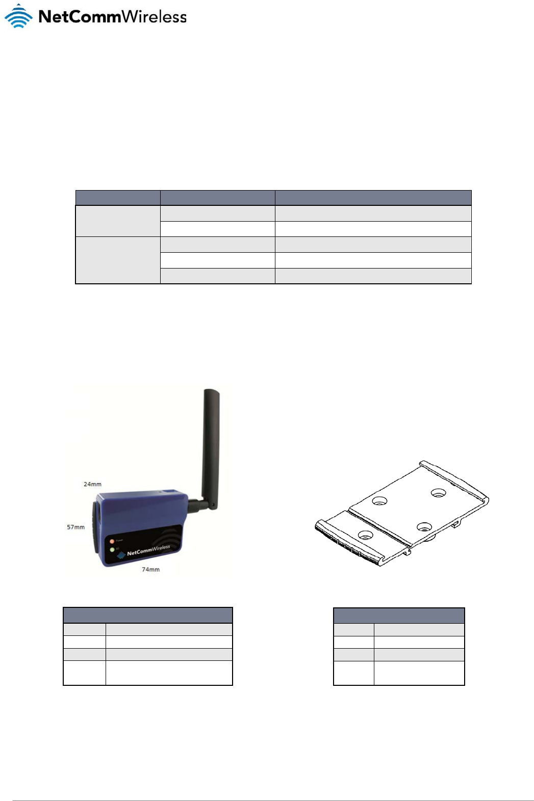
Inserting the SIM card
Please ensure that the NTC-3000 is not connected to the power cable before proceeding.
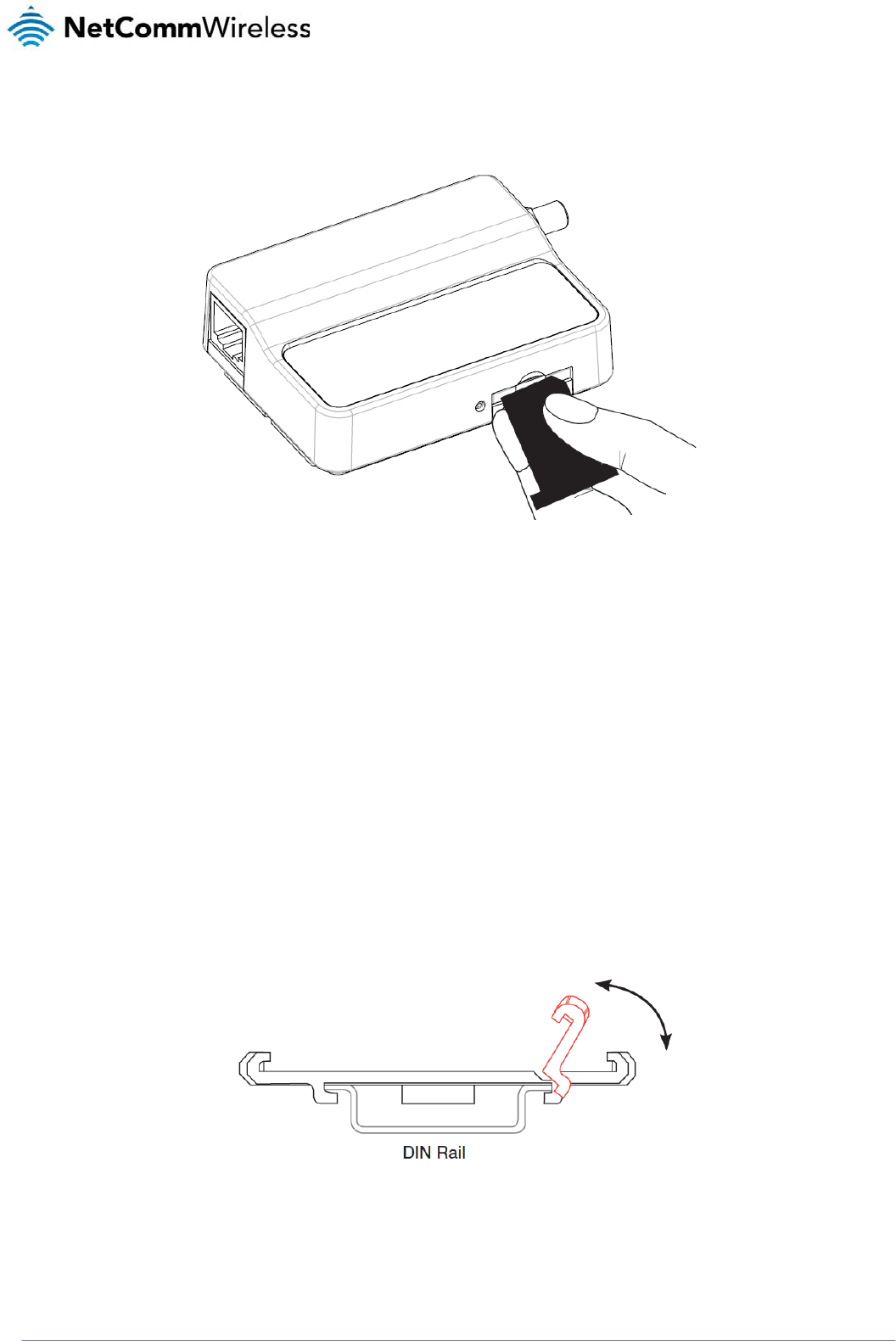
1. Push the small yellow button besides the SIM card holder.
Figure3–AccessingtheNTC‐3000SIMCardSlot
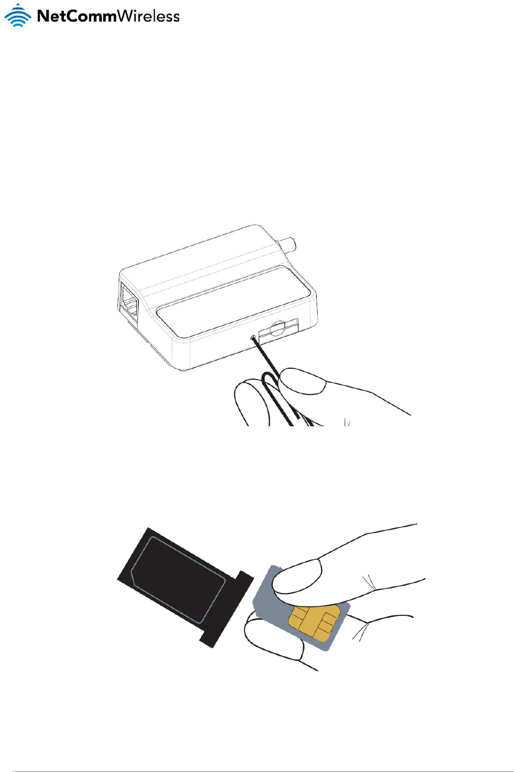
2. Insert the SIM card into the holder with the golden SIM conductor pins facing up.
Figure4‐InsertingaSIMCardintotheNTC‐3000SIMCardHolder
NTC-3000 Series
www.netcommwireless.com
NTC 3000 Series –
M2M
Serial Modem
11
3. Insert the loaded SIM card holder with the SIM conductor pins facing down into the NTC-3000.
Figure5–FaceDownInsertionoftheSIMCardandSIMCardHolder
Mounting the device
The NTC-3000 series modem can be mounted on the wall or a DIN rail by using the mounting bracket. The mounting bracket is made from polyamide, which is a flexible material.
Mounting the NTC-3000 series modem is as simple as bending the mounting bracket to snap into place on the Type-O (Top Hat) DIN rail. This holds the NTC-3000 series modem in
place securely.
Alternatively, the mounting bracket can be screwed onto a wall to provide a permanent fixture.
DIN rail mounting
The NTC-3000 Series mounting bracket has been designed to fit a TS 35 Type-O DIN rail with a 25mm core.
1. Bend / Flex the mounting bracket at the bend line so that the ridges are able to ‘hold’ onto the DIN rail edges as per the diagram above. You also have the option of securing
the mounting bracket further by screwing it into place on the rail.
Figure6‐NTC‐3000‐MountingBracket‐DINRail
NTC 3000 Series – M2M Serial Modem
12 www.netcommwireless.com
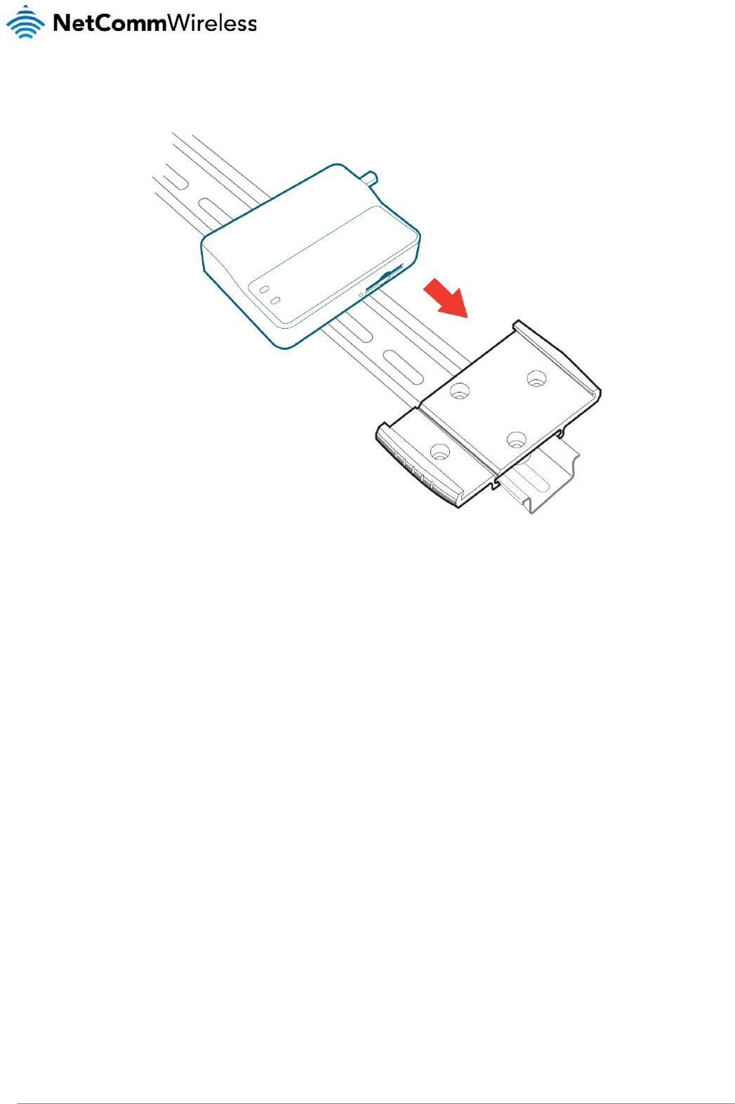
2. Once the bracket is attached to the DIN rail, slide the NTC-3000 Series modem into the mounting bracket to securely fix it in place.
Figure7‐SecuringtheNTC‐3000MountingBrackettotheDINRail
Wall Mounting
1. Select a position on the wall where you would like to mount the NTC-3000 Series modem. Attach the mounting bracket to the chosen wall or ceiling by using the 4 screw holes
(screws not included).
2. Once the bracket is attached to the DIN rail, slide the NTC-3000 Series modem into the mounting bracket to securely fix it in place.
www
.netcommwireless.com
Connecti
n
There are two meth
V
V
Connecting vi
a
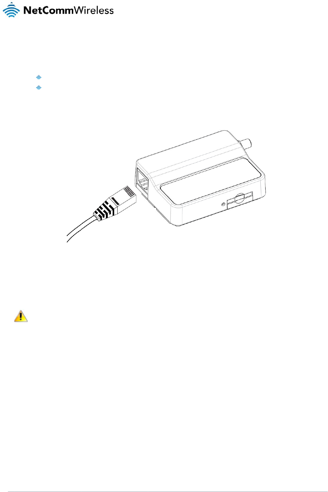
1. Connect the
2. Plug the opti
NTC-3000.
3. Connect a c
o
Please n
the mini-
n
g the Dat
a
ods of connecting th
V
ia RJ-45 connector
V
ia USB 2.0 port usi
n
a
RJ-45 connec
t
optional antenna to
t
onal RS-232 data/p
o
o
mpatible power ad
a
ote: It is not possibl
e
-
USB cable.
a
/ Power
c
e NTC-3000 to your
using a DB9 serial/
p
n
g a Mini USB cable
t
or
Figure
t
he SMA connector
o
o
we
r
cable into the R
J
a
pter to the DC pow
e
e
to use the mini-US
B
c
ables
c
omputer:
ower adapter cable
8‐Connectingthe
R
o
f the NTC-3000.
J
-45 socket of the N
T
e
r
j
ack (2.1mm barrel
B
and Serial connecti
o
RJ‐45Ethernet/P
o
T
C-3000 and then pl
u
l
) of the RS-232 data
/
on concurrently. Ma
k
o
werCabletotheN
u
g the serial port () e
/
power cable and th
e
k
e sure any open co
n
TC
‐3000
nd into the COM por
t
e
n plug the power a
d
n
nection on the Seria
NT
C
NTC 30
0
r
t of the device that
w
d
apter into a power
o
a
l port is disabled be
f
C
-3000 Serie
s
0 Series –
M2M
Serial
w
ill connect to the
utlet.
f
ore connecting via
s
Modem
13

NTC 3000 Series – M2M Serial Modem
14 www.netcommwireless.com
www
.netcommwireless.com
Connecting vi
a
The mini USB conn
e
(such as HyperTer
m
Watcher applicatio
n
NetComm Wireless
website at http://w
w
The following proc
e
Note:
D
1. Open “My C
o
2. Double-clic
k
installation.
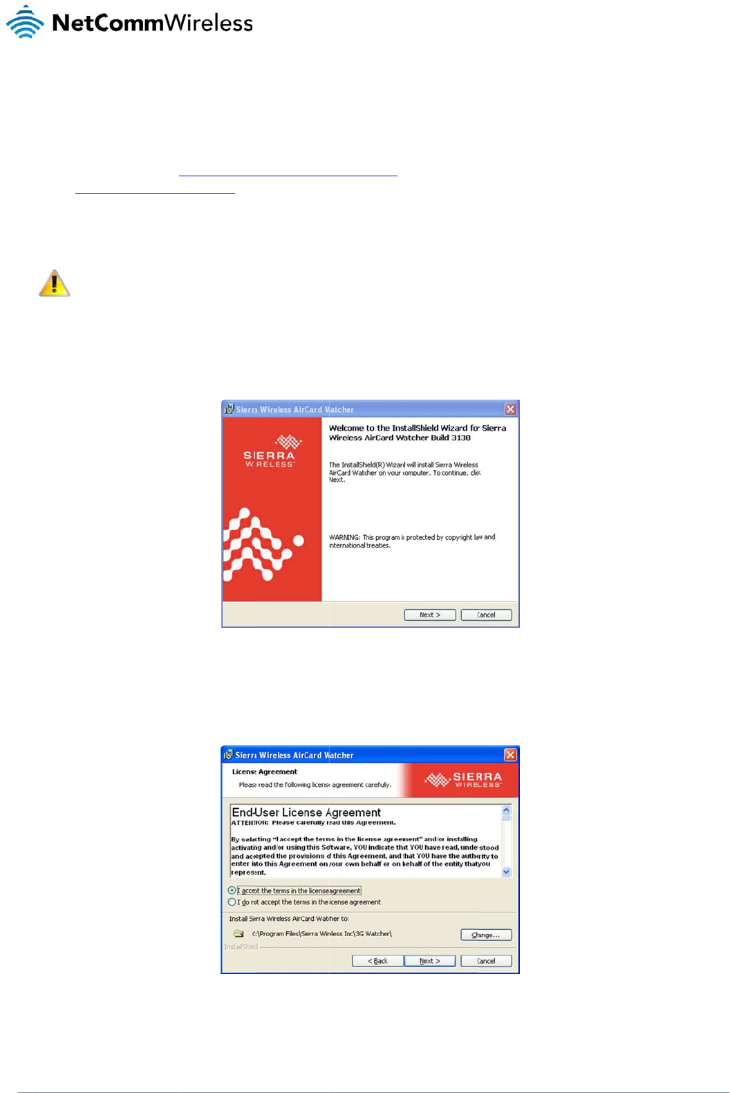
3. The End Us
e
location that
a
Mini USB port
ection enables com
m
m
inal). To configure
t
n
can also be used t
o
Support website at
h
w
w.sierrawireless.co
m
e
dure demonstrates
h
D
o not connect the
N
o
mputer” and navig
a
k
on the Watcher_Ge
n
e
r License Agreeme
n
the application is in
s
m
unication from a Wi
n
t
he internet connecti
o
o
establish the broa
d
h
ttp://support.netco
m
m
/support.aspx.
h
ow to install the Air
C
N
TC-3000 Series Rou
t
a
te to the folder whe
r
n
eric.msi file to open
Fi
g
n
t is displayed. If you
s
talled to, click the C
Figure10‐
AI
n
dows computer via
o
n settings of the rou
t
d
band connection an
d
m
mwireless.com/pro
d
C
ard Watcher applic
a
t
er to the computer
u
e you saved the Air
C
the installation wiza
r
ure9‐
A
IrCardWa
t
agree with the term
s
h
ange button and c
h
I
rCardWatcherIns
t
a virtual COM port.
T
ter, the AirCard Wat
c
d includes the drive
r
d
uct/m2m/ntc-3000.
o
a
tion on Windows X
P
u
ntil the AirCard Wat
c
C
ard Watcher applic
a
r
d. The AirCard Wat
c
t
cherInstallShield
W
s
of the agreement s
e
h
oose the location to
t
allShieldWizardE
n
T
he NTC-3000 Serie
s
c
her application mus
r
necessary to install
o
r for the most up to
d
P
:
c
her application has
a
tion.
c
her Installation Wel
c
W
izardWelcomeSc
r
e
lect “I accept the te
install the applicatio
n
n
d‐UserLicenseAgr
e
s
modem can then b
e
t
be installed on you
r
t
he modem on your
c
d
ate version of the s
o
been installed.
ome screen is displ
a
r
een
rms in the license a
g
n
. Click Next > to co
n
e
ementScreen
NT
C
NTC 30
0
e
configured via a te
r
r computer. The Sier
c
ompute
r
. It can be
d
o
ftware, please visit t
a
yed. Click Next > to
g
reement”. If you wa
n
n
tinue.
C
-3000 Serie
s
0 Series –
M2M
Serial
r
minal emulator
r
a Wireless AirCard
d
ownloaded from th
e
h
e Sierra Wireless
begin the
n
t to change the
s
Modem
15
e
NTC
16
3000 Series – M2M S
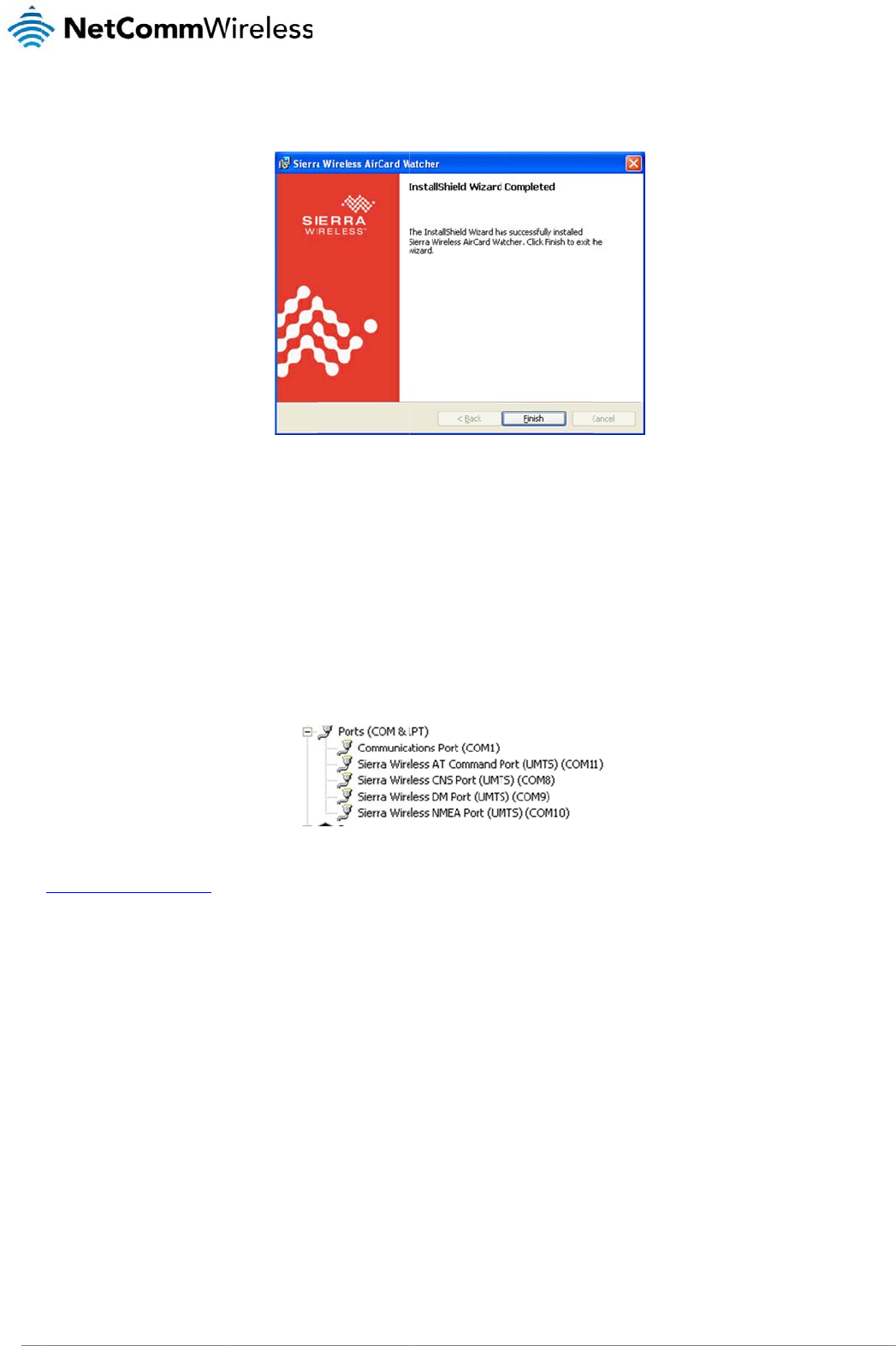
4. The installati
Verifying succ
e
To verify the driver
w
1. Click on the
2. Double click
3. Click on the
4. The Device
L
and you ma
y
If the Sierra Wirele
s
http://support.netco
erial Modem
on wizard will proce
e
e
ssful installati
o
w
as successfully ins
t
Start button and nav
k
on the System Cont
Hardware tab and th
L
ist displays the follo
y
wish to use this po
r
s
s COM ports are no
t
mmwireless.com
/
e
d to install the soft
w
Figu
o
n of the driver
t
alled, check in the
D
igate to the Control
P
rol Panel item.
en click the Device
M
wing COM ports. Ta
k
r
t to communicate wi
t
Figur
e
t
listed, please reboo
w
are and when it has
f
re11‐
A
IrCardWa
t
D
evice Manager for
e
P
anel option.
M
anage
r
button.
k
e note of the COM
p
t
h the modem via a t
e
e
12‐NTC‐3000US
B
t your computer and
finished, the InstallS
h
t
cherInstallShield
W
e
xtra COM ports. To
c
p
ort number of the Si
e
rminal emulator. In
t
B
DriverInstallatio
n
attempt the installat
i
h
ield Wizard Compl
e
W
izardCompleted
S
c
heck the Device M
a
erra Wireless AT Co
m
t
his example, it is C
O
n
‐DeviceManager
on again. If this still
f
ted screen is displa
y
S
creen
nager, perform the f
o
m
mand Port as this
w
O
M11.
Details
f
ails, please contact
N
y
ed. Click Finish to c
o
llowing steps:
w
ill vary depending o
NetComm Wireless
T
www.netcommwirele
s
lose the wizard.
n your environment
T
echnical Support at
s
s.com

NTC-3000 Series
www.netcommwireless.com
NTC 3000 Series –
M2M
Serial Modem
17
NTC
18
3000 Series – M2M S
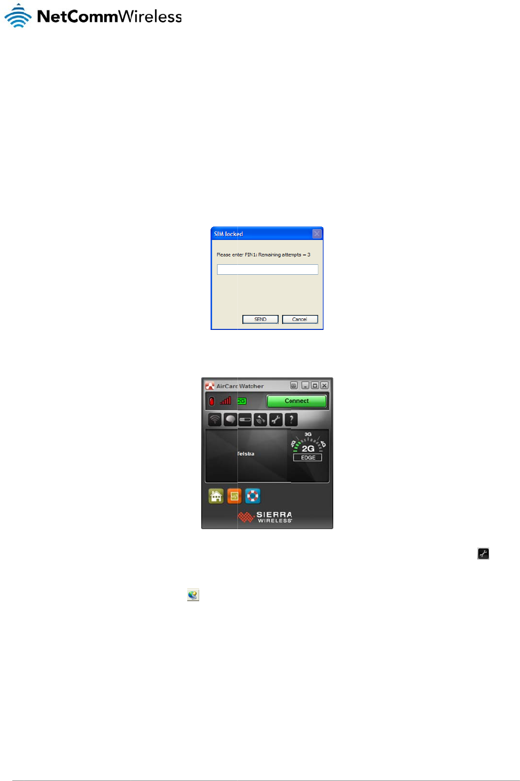
Esta
b
Using the
The NTC-3000 Seri
e
1. Connect the
prompt you
f
2. When the PI
N
3. In many cas
e
to access th
e
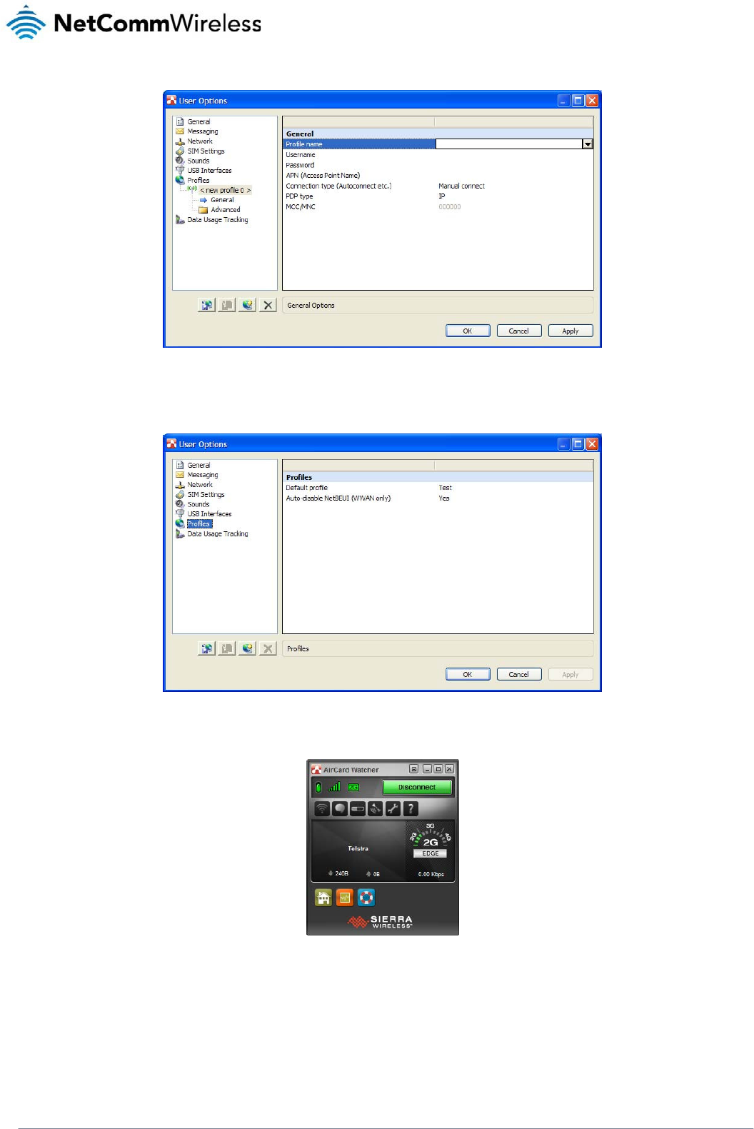
4. Click Profile
s
When you a
r
erial Modem
b
lishi
n
Mini USB
e
s Routers can use t
NTC-3000 to your c
o
f
or the PIN to unlock
N
is verified, the Air
C
e
s you will be able t
o
e
configuration optio
s
from the menu on t
h
r
e done click Apply.
n
g a
M
port
he Sierra Wireless Ai
o
mputer using a mini
it. Enter the PIN and
C
ard Watcher applic
a
o
click the Connect b
ns.
h
e left and then clic
k
M
obil
rCard Watcher appli
USB cable. The Air
C
click SEND.
Figure
a
tion will be displaye
d
Figure14
‐
utton to establish a
c
to add a new
p
e br
o
cation to establish a
n
C
ard Watcher applic
a
13‐SIMlockedPI
N
d
:
‐
A
irCardWatcher
M
c
onnection immediat
e
p
rofile. Enter a Profil
e
o
adb
a
n
internet connectio
n
a
tion should automa
t
N
Prompt
M
ainScreen
e
ly if the software w
a
e
Name, Username
a
a
nd c
o
. To begin using the
t
ically start up and if
y
s able to determine
a
nd Password (if req
u
o
nne
c
NTC-3000 Series R
o
your SIM card is PI
N
a
default APN. If not,
u
ired) and APN (Acc
e
www.netcommwirele
s
c
tion
o
uter:
locked, it will
click the icon
e
ss Point Name).
s
s.com
NTC-3000 Series
www.netcommwireless.com
NTC 3000 Series –
M2M
Serial Modem
19
Figure15‐AIrCardWatcherOptions‐AddNewProfileScreen
5. With the Profiles menu option selected, use the Default Profile drop down list on the right side of the screen to select the profile you created and click OK.
Figure16‐AIrCardWatcherOptions‐ProfilesOptions
6. Click Connect to connect to the mobile broadband network. When you are connected, the Connect button changes to a Disconnect button.
Figure17‐AirCardWatcherApplication–Connected
NTC
20
3000 Series – M2M S
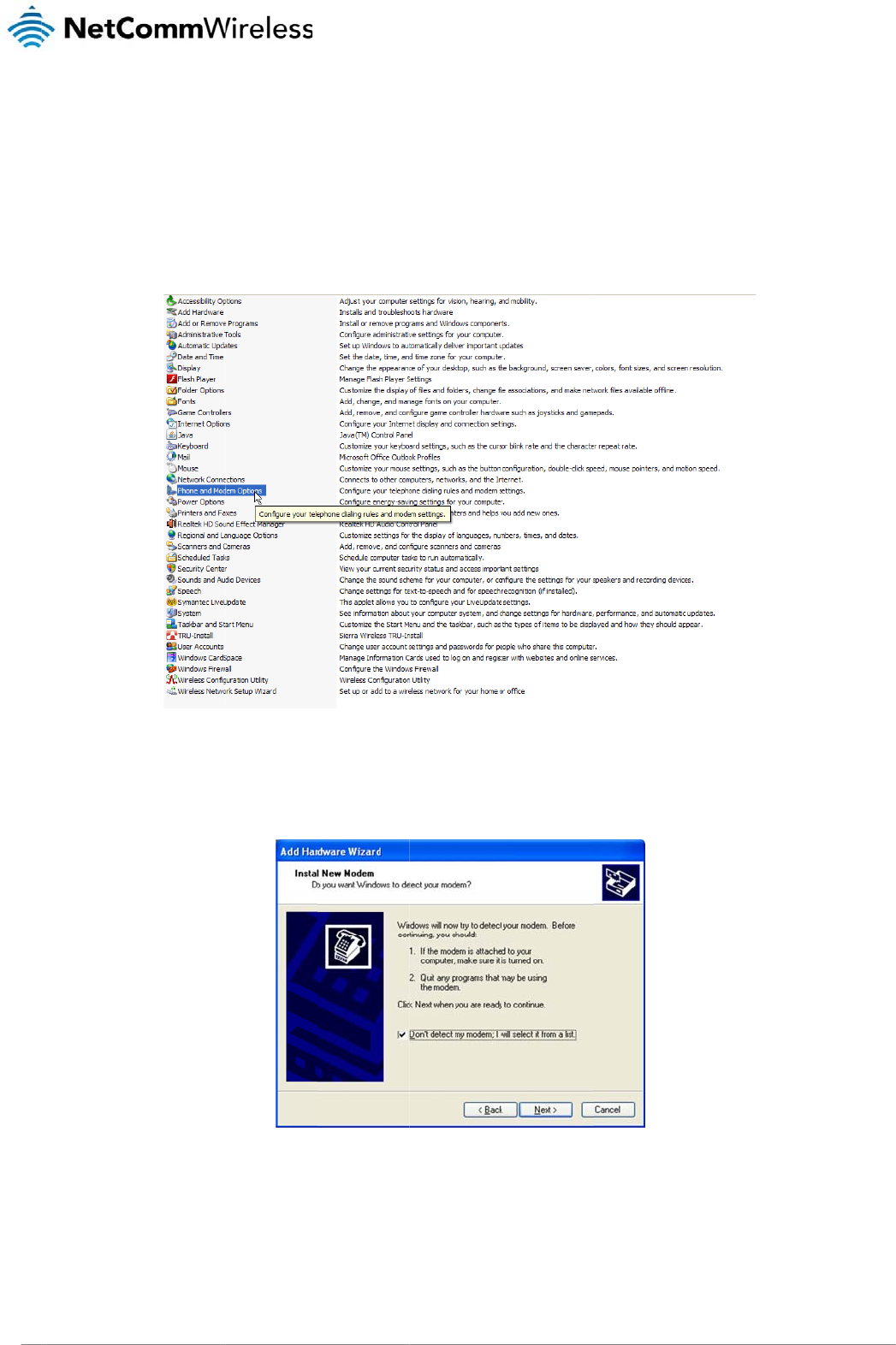
Using the
The NTC-3000 can
process using Win
d
1. Click Start a
n
2. Double click
3. On the Phon
4. Select Don’t
erial Modem
RJ-45 co
n
be used to dial up t
o
d
ows XP, however si
m
n
d then Control Pan
e
k
Phone and Modem
e and Modem Optio
n
detect my modem; I
n
necto
r
o
the internet and pr
o
m
ilar steps can be u
s
e
l.
Options.
n
s window, click Ad
d
will select it from a
Fi
g
o
vide networking usi
n
s
ed in other operatin
g
Figure18‐Contr
o
d
list and then click N
e
g
ure19‐
A
ddHard
w
n
g a standard serial
m
g
systems.
r
olPanel‐Phonea
n
e
xt.
w
areWizard‐Don'
t
m
odem driver. Exam
n
dModemOptions
t
DetectModemO
p
p
le screenshots are
s
tion
shown below to de
m
www.netcommwirele
s
onstrate this
s
s.com
www
.netcommwireless.com
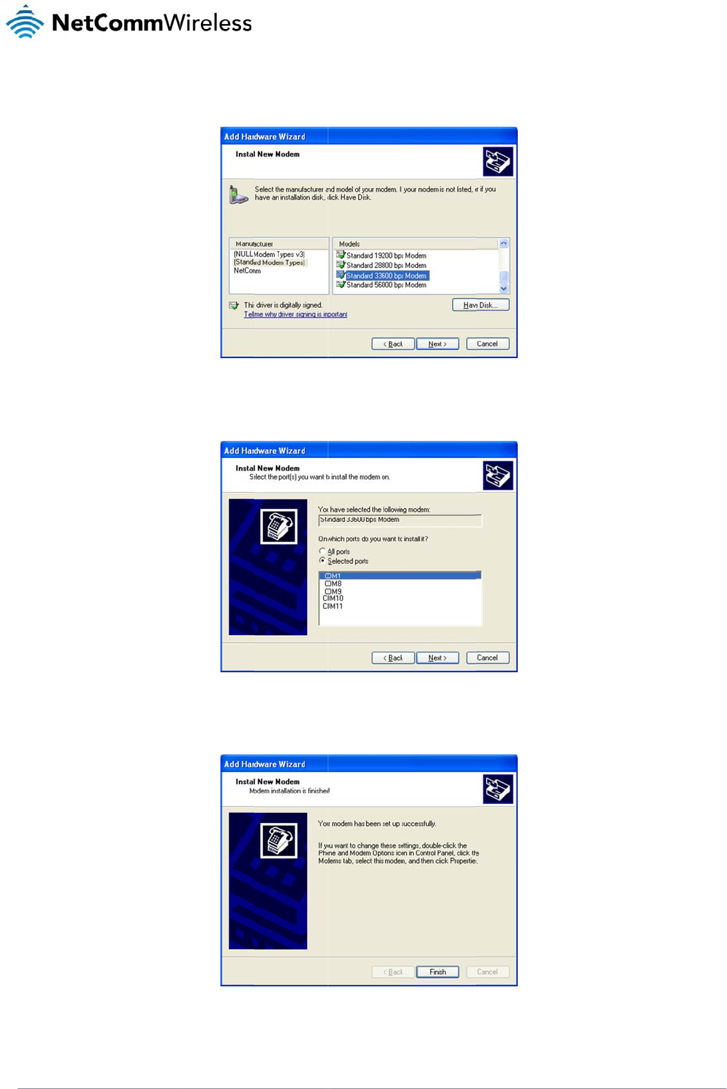
5. Wait a few
m
6. Select the p
o
7. Wait a few
m
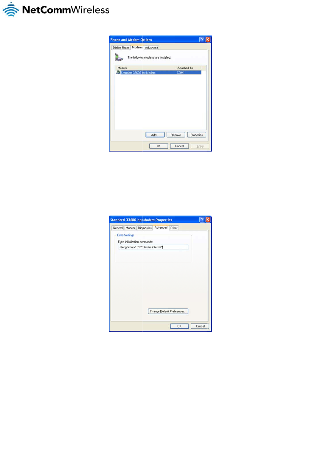
8. The modem
ensure that t
m
oments until the list
i
o
rt that the NTC-300
0
m
oments whilst Wind
o
must now be modifi
e
t
he new modem is s
e
i
s loaded, then sele
c
Fig
0
is connected to an
d
o
ws installs the drive
r
Fig
e
d to add a special i
n
e
lected on the Phone
t Standard 33600 b
p
ure20‐
A
ddHard
w
d
select Next. In the
e
Figure21‐
r
and click Finish on
t
u
re22‐
A
ddHard
w
n
itialisation string to
p
and Modem menu,
p
s modem from the li
s
w
areWizard‐Stan
d
e
xample screenshot
‐
A
ddHardwareWi
z
the final screen of th
w
areWizard‐Mod
e
p
ass the APN inform
a
and click Propertie
s
s
t, and click Next.
d
ard33600kbpsMo
below, the NTC-300
0
z
ard‐COM1
e
wizard.
e
mInstalledSucces
s
a
tion required by yo
u
s
.
d
em
0
is connected via th
e
sf
ull
y
u
r service to connect
NT
C
NTC 30
0
e serial cable to por
t
to the cellular netw
o
C
-3000 Serie
s
0 Series –
M2M
Serial
t
COM1.
rk. To do this,
s
Modem
21
NTC
22
3000 Series – M2M S
9. Click on the
A
at+cgd
c
The ‘apn’ is
y
Click OK.
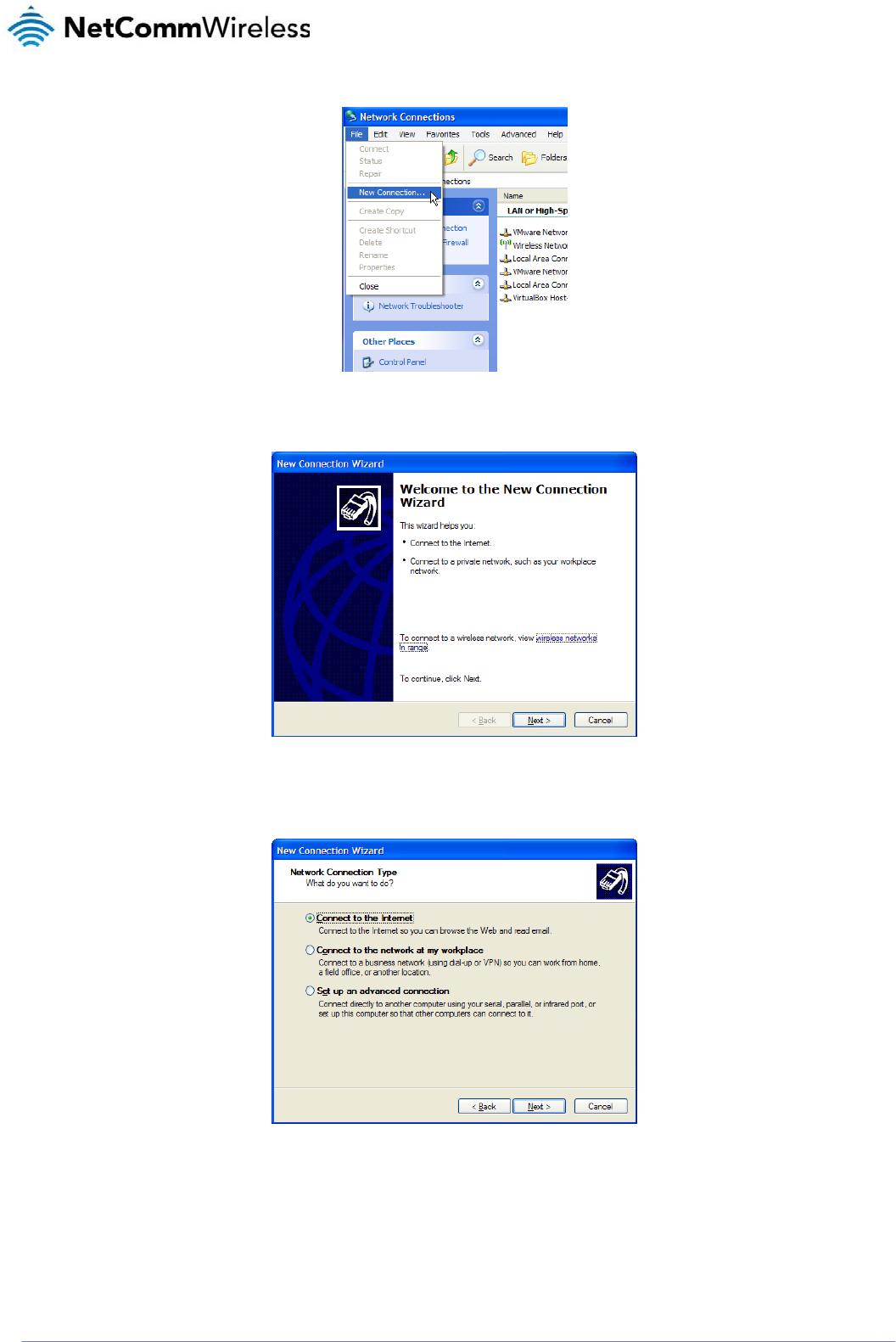
10. Click on Sta
r
11. Click on File
erial Modem
Advanced tab, and t
y
c
ont=1,"IP"
,
y
our Access Point N
a
r
t then Control Panel
then New Connecti
o
y
pe the following init
i
,
"apn"
a
me e.g. for Telstra
y
Figure24‐
S
, then double-click o
o
n.
Figure23‐Phon
e
alization commands
y
ou would type at+
S
tandard33600kbp
s
n Network Connecti
o
e
andModemOpti
o
in the Extra initializ
a
cgdcont=1,"
s
ModemPropertie
o
ns.
o
ns‐ModemsTab
a
tion commands field
IP","telst
r
s
‐Extrainitializati
o
:
r
a.internet
"
o
ncommands
"
www.netcommwirele
s
s
s.com
NTC-3000 Series
www.netcommwireless.com
NTC 3000 Series –
M2M
Serial Modem
23
Figure25‐NetworkConnections‐NewConnection
12. The New Connection Wizard is displayed. Click Next > to begin.
Figure26‐NewConnectionWizardWelcomeScreen
13. Select Connect to the Internet and click Next >.
Figure27‐NewConnectionWizard‐Connecttotheinternet
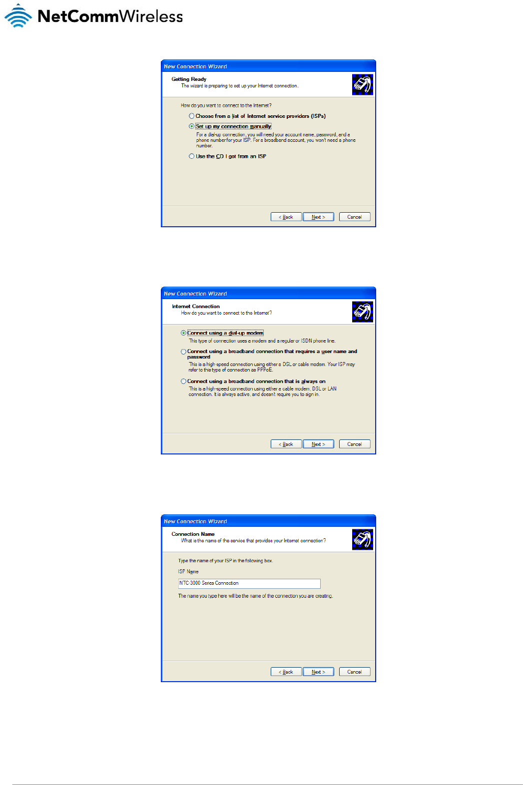
14. Select Setup my connection manually and click Next >.
NTC 3000 Series – M2M Serial Modem
24 www.netcommwireless.com
Figure28‐NewConnectionWizard‐Setupmyconnectionmanually
15. Select Connect using a dial-up modem and click Next >.
Figure29‐NewConnectionWizard‐Connectusingadial‐upmodem
16. Enter a name for the ISP or connection and click Next >.
Figure30‐NewConnectionWizard‐ConnectionName
NTC-3000 Series
www.netcommwireless.com
NTC 3000 Series –
M2M
Serial Modem
25
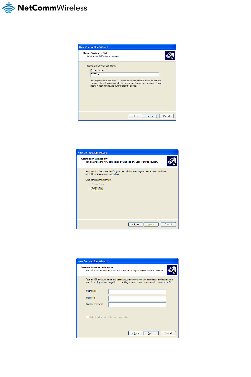
17. In the Phone Number field, enter *99***1#
Click Next >.
Figure31‐NewConnectionWizard‐PhoneNumber
18. Select For my use only and click Next >.
Figure32‐NewConnectionWizard‐Myuseonly
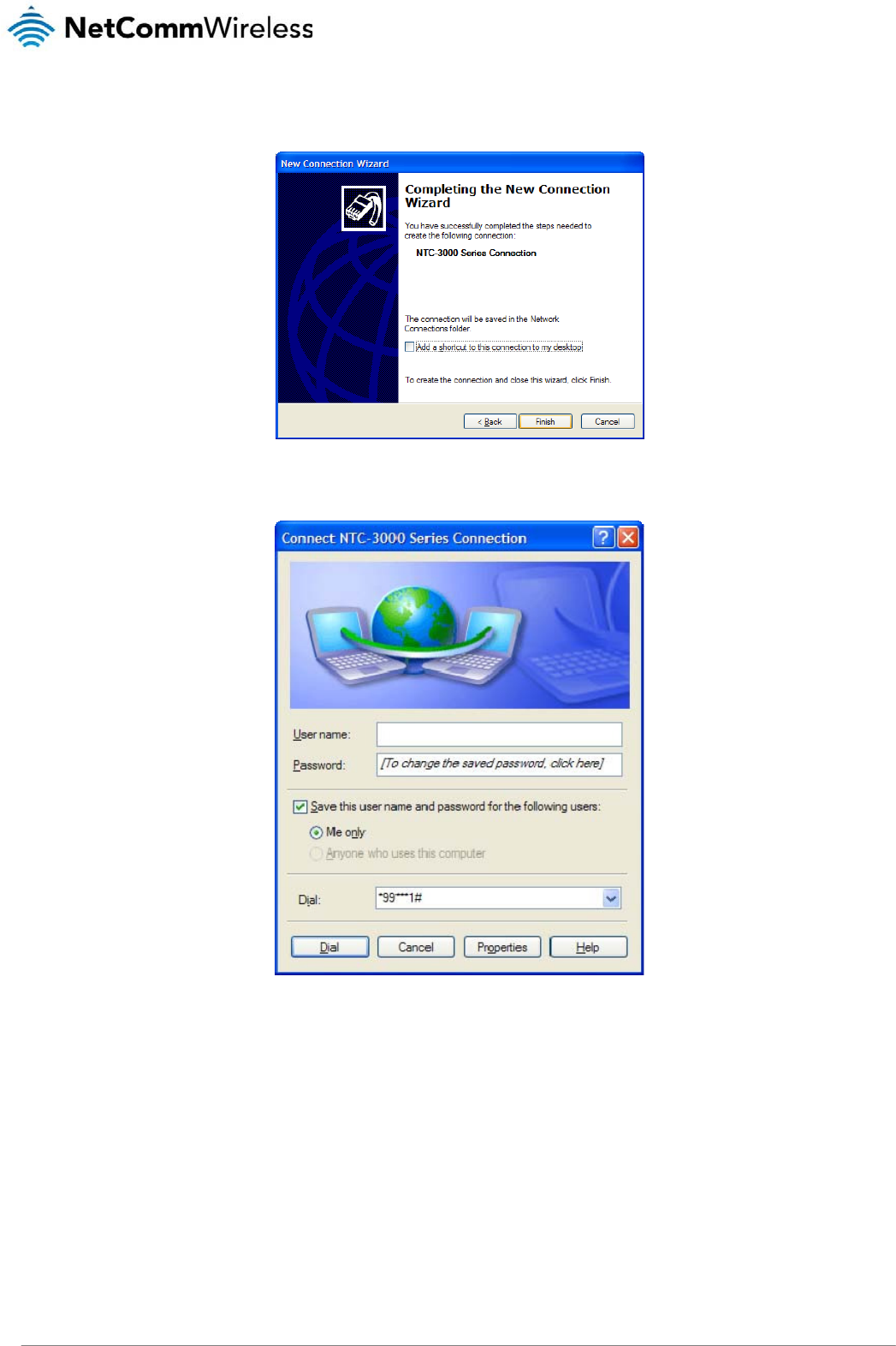
19. If the service from your wireless service provider requires authentication, please enter a username/password into the relevant fields. Your service provider can provide this
information if they are required. Click Next >.
Figure33‐NewConnectionWizard‐UsernameandPassword
NTC 3000 Series – M2M Serial Modem
26 www.netcommwireless.com
20. Click Finish.
Figure34‐NewConnectionWizardCompleteScreen
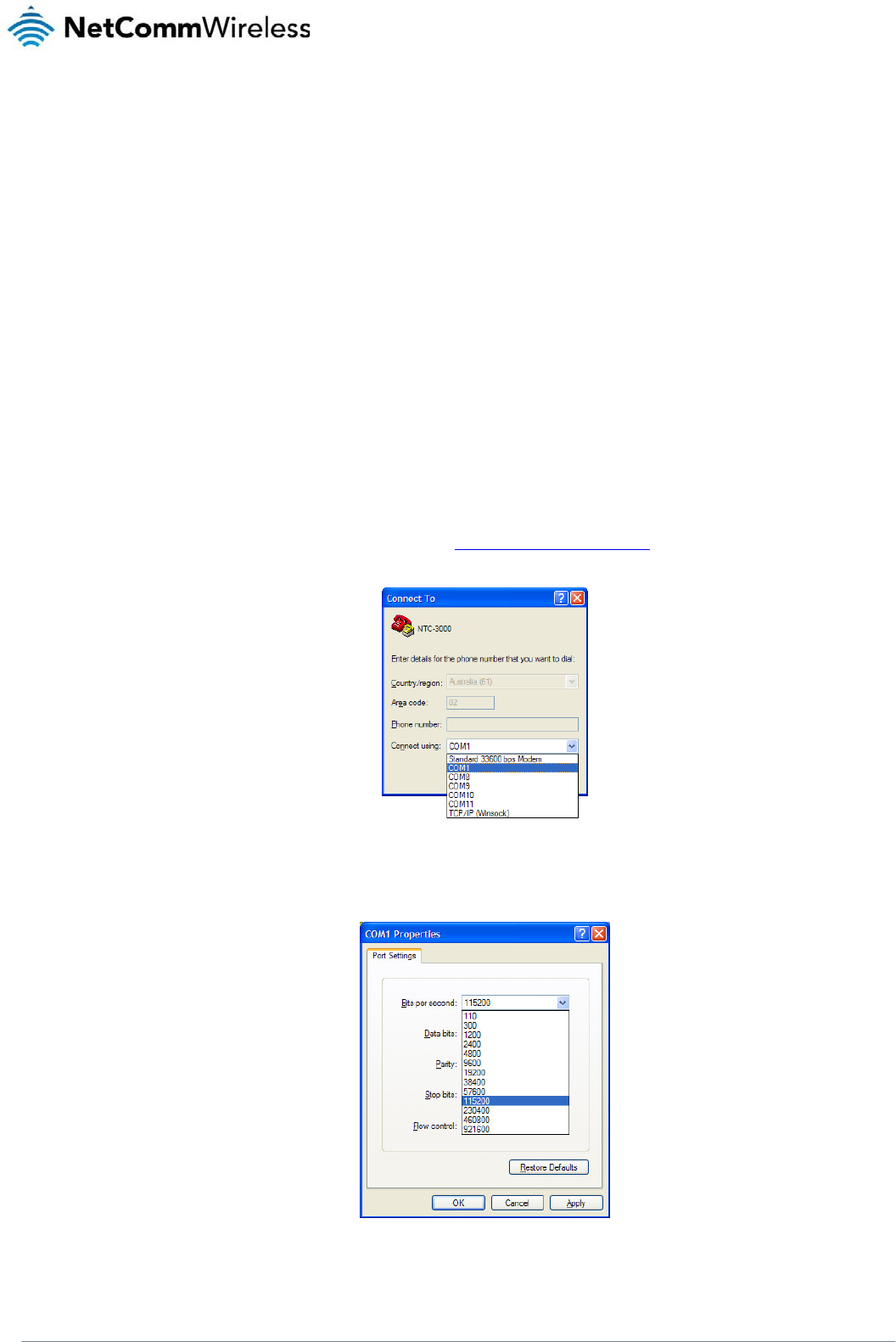
21. When you click Finish, the connection window opens prompting you to establish a connection. Click Dial to begin using your NTC-3000 network connection.
Figure35‐ConnecttoDial‐upPrompt
NTC-3000 Series
www.netcommwireless.com
NTC 3000 Series –
M2M
Serial Modem
27
Communicating with an NTC-3000 Series
Modem
Dumb Terminal
Any terminal emulator can be used to facilitate communication with the NTC-3000 after the Virtual COM port has been installed using either the device’s serial port or the USB port.
Additionally, you can select to communicate with the modem using your computer’s serial port COM port. The example below demonstrates how to use HyperTerminal in Windows XP.
1. Click on the Start button and then navigate to the Accessories item and then Communications.
2. Click on the HyperTerminal item.
3. Enter a name for the connection profile (for example: NTC-3000) and click OK.
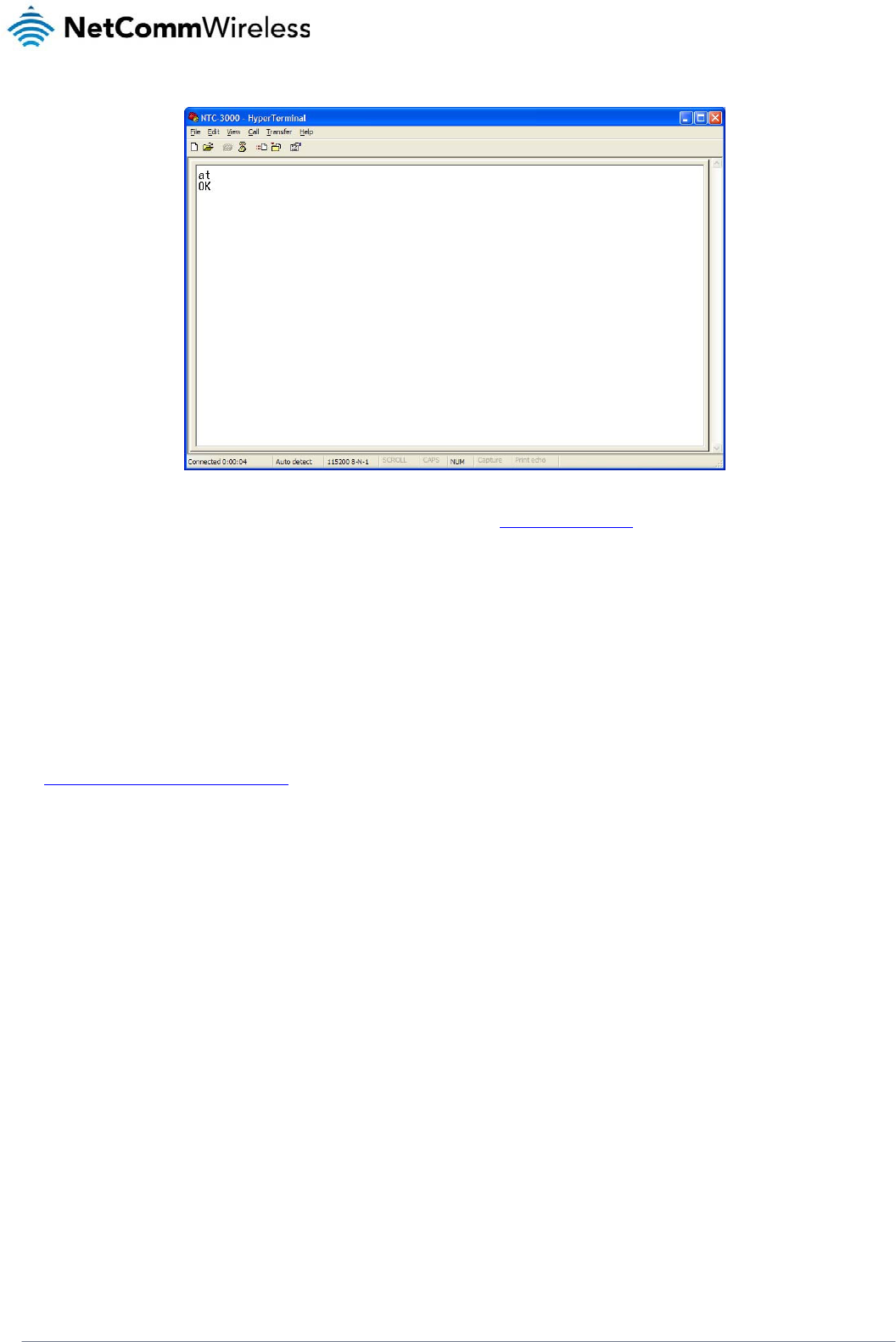
4. On the “Connect to” window, use the “Connect using” dropdown menu to select the virtual COM port (which was created by installing the AirCard Watcher) or the COM port to
which the modem is connected if using the DB9 serial/power adapter cable. See the Verifying successful installation of the driver section to determine the correct port number
of the virtual COM port.
Figure36‐NTC‐3000OperationSettings‐SelectCOMPort
5. On the COM port settings window that appears, in the Bits per second drop down menu, select 115200.
Figure37‐NTC‐3000OperationSettings‐BaudRateSelection

NTC 3000 Series – M2M Serial Modem
28 www.netcommwireless.com
The terminal window display indicates that a connection is open to the NTC-3000 Series. This can be confirmed by entering the command at and receiving the response OK as
shown below:
NTC-3000 Series
www.netcommwireless.com
NTC 3000 Series –
M2M
Serial Modem
29
Using a terminal emulator such as HyperTerminal and the AT command Reference Guide, the NTC-3000 Series router can be configured to perform customised operations. Please
refer to the Supported AT Command Reference Guide available on the NetComm Wireless website at http://www.sierrawireless.com for more information on the functions available.
If you are unable to type at, check that you have selected the correct COM port for the NTC-3000. Alternatively, try to open a connection using a physical COM port with a DB9
serial/power adapter cable attached.
Open AT Application Framework
The NetComm Wireless NTC-3000 Series Routers support the Open AT Application Framework. The Open AT application framework consists of an M2M specific operating system,
libraries and development studio allowing the accelerated creation of embedded M2M applications and sharing of processing resources.
To begin developing M2M applications, download the Open AT Application Framework on the Sierra Wireless developer website at
http://developer.sierrawireless.com/OpenAT/download
NTC
30
3000 Series – M2M S
Net
C
Appl
The NTC-3000 co
m
functionality and su
TCP/UDP servers (
t
Please
may b
e
The NTC-3000 mo
d
NUMBE
R
0
1
2
3
Comman
d
The following is a c
o
AT+PAD
Description: Speci
Usage 1:
Usage 2:
Help:
Options:
Example: To s
w
erial Modem
C
omm
icati
o
m
es pre-loaded with
a
pport fo
r
a number
o
t
ypically another NT
C
note: Installing anot
h
e
used at a time.
d
em has 4 modes av
a
R
MOD
Disabled
TCP Client
TCP Server
UDP Client
d
List
omplete list of com
m
fies the NTC-3000 o
p
To set the o
p
AT+PAD
=
where ‘x’ is
a
To retrieve t
h
AT+PAD
?
AT+PAD
=
0
1
2
3
w
itch the NTC-3000 t
o
AT+PAD
=
Wir
e
o
n
a
NetComm Wireless
o
f terminal command
s
C
-3000) using GSM/
G
h
er custom applicati
o
a
ilable:
E
In this mode
This is the d
e
The NTC-30
0
The NTC-30
0
m
ands for the NetCo
m
p
eration mode.
p
eration mode
=
x
a
n option number.
h
e currently configur
e
?
=
?
disabled
tcp client
tcp server
udp client
o
TCP client mode, e
n
=
1
e
less
O
Open AT custom ap
s
specific to this ap
p
G
PRS connections.
o
n will cause the Ne
t
, the Serial to TCP gatewa
y
e
fault mode. The NTC-300
0
0
0 accepts incoming IP c
o
0
0 transfers UDP data bet
w
m
m Wireless Open A
T
e
d operation mode
n
te
r
O
pe
n
p
plication. This appli
c
p
lication. These com
m
t
Comm Wireless Op
e
y
function is disabled and
t
0 transfers TCP data betw
e
o
nnections and transfers d
a
w
een the serial and IP con
T
custom application
AT
C
c
ation allows the NT
C
m
ands can be used l
e
n AT custom applic
a
DESCRIPTION
t
he NTC-3000 behaves as
e
en the serial and IP conn
e
a
ta between serial and IP
c
n
ections.
:
C
usto
m
C
-3000 to operate in
d
o
cally or by SMS to
s
a
tion to cease functi
o
a normal modem.
e
ctions.
c
onnections.
m
d
ifferent modes, pro
v
s
end or receive seri
a
o
ning as only one cu
s
www.netcommwirele
s
v
iding additional
a
l data to or from
s
tom application
s
s.com

NTC-3000 Series
www.netcommwireless.com
NTC 3000 Series –
M2M
Serial Modem
31
AT+APN
Description: Sets the Access Point Name (APN) used to connect to the broadband network. The default setting is blank.
Usage 1: To set the APN
AT+APN=xxxx
where ‘xxxx’ is the APN that you wish to use.
Usage 2: To retrieve the currently configured APN
AT+APN?
Example: To set the APN to ‘testAPN’ enter
AT+APN=testAPN
AT+USER_PASS
Description: Sets the username and password used to connect to the broadband network.
Usage 1: To set the username and password
AT+USER_PASS=”xxxx”,”xxxx”
Usage 2: To retrieve the currently configured username and password
AT+USER_PASS?
Help: AT+USER_PASS=?
Options: username the user name for the broadband account
password the password for the broadband account
Example: To configure the username as ‘user1’ and password as ‘testpass’ enter
AT+USER_PASS=”user1”,”testpass”
AT+SERIAL_BAUD
Description: Sets the baud rate used for communication between the modem and the connected device.
Usage 1: To set the baud rate
AT+SERIAL_BAUD=[baud]
Usage 2: To retrieve the currently configured baud rate
AT+SERIAL_BAUD?
Help: AT+SERIAL_BAUD=?
Options: 300, 600, 1200. 2400. 4800, 9600, 19200, 38400, 57600, 115200 (default value), 230400, 460800, 921600.
Example: To configure the baud rate to 115200bps enter
AT+SERIAL_BAUD=115200

NTC 3000 Series – M2M Serial Modem
32 www.netcommwireless.com

NTC-3000 Series
www.netcommwireless.com
NTC 3000 Series –
M2M
Serial Modem
33
AT+SERIAL_FORMAT
Description: Sets the serial format used for communication between the modem and the connected device.
Usage 1: To set the serial format
AT+SERIAL_FORMAT=x
where ‘x’ is an option number.
Usage 2: To retrieve the currently configured serial format
AT+SERIAL_FORMAT?
Help: AT+SERIAL_FORMAT=?
Options: 1 8 data 2 stop
2 8 data 1 parity 1 stop
3 8 data 1 stop – default value
4 7 data 2 stop
5 7 data 1 parity 1 stop
6 7 data 1 stop
Example: To set the serial format to 8 data 2 stop enter
AT+SERIAL_FORMAT=1
AT+SERIAL_FLOW
Description: Sets the flow control used for communication between the modem and the connected device.
Usage 1: To set the flow control
AT+SERIAL_FLOW=x
Where ‘x’ is an option number.
Usage 2: To retrieve the currently configured flow control setting
AT+SERIAL_FLOW?
Help: AT+SERIAL_FLOW=?
Options: 0 no flow control, default value
2 hardware, RTSCTS
Example: To set no flow control enter
AT+SERIAL_FLOW=0

NTC 3000 Series – M2M Serial Modem
34 www.netcommwireless.com
AT+SERIAL_PARITY
Description: Sets the serial parity used for communication between the modem and the connected device.
Usage 1: To set the serial parity
AT+SERIAL_PARITY=x
where ‘x’ is an option number.
Usage 2: To retrieve the currently configured serial parity
AT+SERIAL_PARITY?
Help: AT+SERIAL_PARITY=?
Options: 0 Odd
1 Even
4 No parity, default value
Example: To set no serial parity enter
AT+SERIAL_PARITY=4
AT+SERVER
Description: Sets the TCP/UDP server IP address and port or hostname and port. In TCP Client mode this command sets the remote TCP server IP address and remote
port number. In TCP Server mode the port number will be used as the local TCP Server port number. In UDP Client mode, this command will set the UDP
server IP address and remote port number. If a remote UDP socket wants to send back data, it must use this port number.
Usage 1: To set the server IP address and port
AT+SERVER=xxx.xxx.xxx.xxx,yyyyy
Where ‘xxx.xxx.xxx.xxx’ is the server IP address and ‘yyyyy’ is the port number
Usage 2: To set the server hostname and port
AT+SERVER=xxxx,yyyyy
Where ‘xxxx’ is the hostname of the server and ‘yyyy’ is the port number. If no port number is specified, the NTC-3000 uses the default port 1516.
Usage 3: To retrieve the currently configured server IP and port
AT+SERVER?
Help: AT+SERVER=?
Options: ip address the ip address of the server
hostname the hostname of the server
port number the port number of the server
Example 1: To set the IP address of the server to 10.1.193.11 and port to 1516, enter
AT+SERVER=10.1.193.11,1516
Example 2: To set the hostname of the server to ‘testhost.domain.com’ and port to 8888, enter

NTC-3000 Series
www.netcommwireless.com
NTC 3000 Series –
M2M
Serial Modem
35
AT+SERVER=testhost.domain.com,8888

NTC 3000 Series – M2M Serial Modem
36 www.netcommwireless.com
AT+Save
Description: Saves any changes made to the settings using commands in this list. Changes to settings using the commands in this list do not take effect immediately
and must be saved to the board’s flash memory using this command, followed by a reboot. The exception to this is the AT+PAD command which initiates a
save command and reboots the device.
Usage: To save settings to the onboard flash memory
AT+SAVE=1
Example: To save settings to the onboard flash memory, enter
AT+SAVE=1
Then enter
AT+CFUN=1
to perform a reboot so that the new settings take effect.
AT+CFUN
Description: This is a standard AT command which resets the device.
Usage: To reset the device
AT+CFUN=1
AT+SMS_DIAGNOSTICS
Description: Sets the status of the SMS Diagnostics feature on the NTC-3000.
Usage 1: To set the status of SMS Diagnostics
AT+SMS_DIAGNOSTICS=x
Where ‘x’ is an option number.
Help: AT+SMS_DIAGNOSTICS=?
Options: 0 disabled
1 enabled
Example: To enable SMS Diagnostics, enter
AT+SMS_DIAGNOSTICS=1

NTC-3000 Series
www.netcommwireless.com
NTC 3000 Series –
M2M
Serial Modem
37
AT+SMS_PASSWORD
Description: Used to define the password used with the SMS Diagnostics feature. The password is limited to 6 characters. The default password is ‘1234’.
Usage 1: To set the SMS password
AT+SMS_PASSWORD=XXXXXX
Usage 2: To retrieve the current configured password
AT+SMS_PASSWORD?
Help: AT+SMS_PASSWORD=?
Example: To set the password to ‘1234’, enter
AT+SMS_PASSWORD=1234
AT+SMS_ACK
Description: Sets the status of the SMS acknowledgement feature. When enabled, the NTC-3000 sends a reply SMS to inform whether the command was successful.
Usage 1: To configure SMS acknowledgments
AT+SMS_ACK=x
Where ‘x’ is an option number.
Usage 2: To retrieve the SMS acknowledgment status
AT+SMS_ACK?
Help: AT+SMS_ACK=?
Options: 0 disabled
1 enabled
Example: To enable SMS acknowledgements , enter
AT+SMS_ACK=1
AT+VERSION
Description: Displays the version number of the NetComm Wireless custom application installed.
Usage: AT+VERSION?

NTC 3000 Series – M2M Serial Modem
38 www.netcommwireless.com
AT+FORCE_RESET
Description: Sets the period for which the NTC-3000 will automatically reset.
Usage 1: To set the force reset period
AT+FORCE_RESET=xxxxx
Where ‘x’ is an integer between 2 and 65535 minutes.
Usage 2: To retrieve the currently configured force reset period
AT+FORCE_RESET?
Help: AT+FORCE_RESET=?
Options: 0 no reset
2 - 65535 minutes between a forced reset
Example: To set the NTC-3000 to reboot every 60 minutes, enter
AT+FORCE_RESET=60
AT+EOL
Description: Send this command to delimit data received from the serial port. The default setting is 0x0D,0x0A.
Usage: AT+EOL=xx,yy
where ‘xx’ is the hexadecimal code for the carriage return character and ‘yy’ is the hexadecimal code of the line feed character.
Help: AT+EOL=?
Example: To configure the carriage return and line feed characters to ‘D’ and ‘A’, enter
AT+EOL=0x0D,0x0A
AT+CHAR_TIMEOUT
Description: By default, data received from the serial interface is buffered for 1*100ms. This can be changed to a value up to 65535 seconds, expressed as a factor of
100ms. After this delay, data will be sent out regardless of end of line input.
Usage 1: To configure the character timeout
AT+CHAR_TIMEOUT=xxx
where ‘x’ is an integer to be multiplied by 100ms between 0 and 255.
Usage 2: To retrieve the currently configured character timeout value
AT+CHAR_TIMEOUT?
Help: AT+CHAR_TIMEOUT=?
Options: 0 disable (always use delimiters instead)
1 – 255 * 100ms
Example: To configure the character timeout to 1 second, enter

NTC-3000 Series
www.netcommwireless.com
NTC 3000 Series –
M2M
Serial Modem
39
AT+CHAR_TIMEOUT=10

NTC 3000 Series – M2M Serial Modem
40 www.netcommwireless.com
AT+TCP_TIMEOUT
Description: This command sets the TCP timeout value in seconds. If the TCP/IP connection is not working, the application will wait for this period of time to re-establish
the connection. The minimum timeout period is 10 seconds while the maximum is 65535 seconds.
Usage 1: To configure the TCP timeout value
AT+TCP_TIMEOUT=xxxxx
Where ‘x’ is an integer in seconds between 10 and 65535.
Usage 2: To read the currently configured TCP timeout value
AT+TCP_TIMEOUT?
Help: AT+TCP_TIMEOUT=?
Example: To set the TCP timeout period to 10 seconds
AT+TCP_TIMEOUT=10
AT+TCP_RETRY
Description: If the NTC-3000 is operating in TCP or UDP client mode and the connection with the server is down, the application will try for the AT+TCP_RETRY number
of times to re-establish the connection with the server, then it will wait for the specified TCP_TIMEOUT period and try again. The minimum value is 0 which
will cause the NTC-3000 to retry the connection until a connection is made while the maximum value is 10.
Usage 1: To set the TCP retry count
AT+TCP_RETRY=xx
where ‘x’ is an integer between 0 and 10.
Usage 2: To retrieve the currently configured TCP retry count
AT+TCP_RETRY?
Help: AT+TCP_RETRY=?
Options: 0 Infinite (always try to connect when connection fails)
1 – 10 times to attempt reconnection
AT+LOCAL_IP
Description: Retrieves the NTC-3000’s allocated WAN IP address.
Usage: AT+LOCAL_IP?
AT+DNS
Description: Retrieves the NTC-3000’s allocated DNS address.
Usage: AT+DNS?

NTC-3000 Series
www.netcommwireless.com
NTC 3000 Series –
M2M
Serial Modem
41
AT+FACTORY_RESET
Description: Resets the NTC-3000 to factory default settings, effectively performing the following commands:
AT + PAD = 0
AT + APN =
AT + USER_PASS = "",""
AT + FORCE_RESET = 0
AT + SERVER = ,1516
AT + SMS_DIAGNOSTICS= 0
AT + SMS_ACK = 0
AT + SMS_PASSWORD = 1234
AT + EOL = 0x0D,0x0A
AT + SERIAL_BAUD = 115200
AT + SERIAL_FORMAT = 3
AT + SERIAL_PARITY = 4
AT + SERIAL_FLOW = 0
AT + CHAR_TIMEOUT = 8 seconds
AT + TCP_TIMEOUT = 10
AT + TCP_RETRY = 0 (Infinite)
AT + DYN_ENABLE = 0
AT + DYN_HOST =
AT + DYN_USER =
AT + DYN_PASS =
Usage: AT+FACTORY_RESET=1
Help: AT+FACTORY_RESET=?
AT+SERIAL_ON_START
Description: This command configures whether the serial port initialises on power up or initialises when there are active connections.
Usage: AT+SERIAL_ON_START=x
where ‘x’ is an option number
Usage 2: AT+SERIAL_ON_START?
Help: AT+SERIAL_ON_START=?
Options: 1 serial port is initialised on power up
0 serial port is initialised when there are active connections

NTC 3000 Series – M2M Serial Modem
42 www.netcommwireless.com
AT+DYN_ENABLE
Description: Instructs the NTC-3000 to enable updating its IP address to the configured Dynamic DNS server.
Usage: AT+DYN_ENABLE=x
Where ‘x’ is an option number
Help: AT+DYN_ENABLE=?
Options: 0 disable
1 enable
Example: To set the NTC-3000 to enable star updates to the Dynamic IP address table, enter
AT+DYN_ENABLE=1
AT+DYN_HOST
Description: Instructs the NTC-3000 to use the supplied hostname to perform an IP address update.
Note: The only dynamic DNS service supported at this time is www.dyndns.org
Usage: AT+DYN_HOST=XXXX
where “XXXX” is the hostname of the dynamic DNS service.
Example: To instruct the NTC-3000 to use ‘testuser.dyndns.org’ as the dynamic DNS hostname to perform an IP address update, enter
AT+DYN_HOST=testuser.dyndns.org
AT+DYN_USER
Description: Configures the username for the dynamic DNS service.
Usage: AT+USER=XXX
Example: To set the dynamic DNS service username to ‘testuser’, enter
AT+USER=testuser
AT+DYN_PASS
Description: Configures the password for the dynamic DNS service.
Usage: AT+PASS=XXX
Example: To set the dynamic DNS service username to ‘testpass1’, enter
AT+USER=testpass1

NTC-3000 Series
www.netcommwireless.com
NTC 3000 Series –
M2M
Serial Modem
43
General Operation
Upon powering up, the application subscribes to the SMS service and sets up customized AT commands. It then reads the configuration from FLASH. If the device is configured in
normal modem mode (AT+PAD=0), the application will not start GSM or GPRS initialization, TCP or UDP preparation routines.
When TCP/IP has been set up, an IP address will be issued to the NTC-3000. The application can then switch to one of the following modes:
TCP client mode
TCP server mode
UDP client mode
The application can switch to any of these modes by AT command or remotely through SMS. The serial port can be initialized while GSM/GPRS registration in progress. If the flash
configuration area is empty, the default parameters are loaded. The default parameters are as follows:
Serial Port
Baud Rate: 115200
Data Bits: 8
Parity: none
Stop Bit: 1
PDP profile
APN :
User:
Password:
TCP Client
Server :
Port: 1516
The NTC-3000 default running mode is with PAD disabled.

NTC 3000 Series – M2M Serial Modem
44 www.netcommwireless.com
Configuration through SMS
The NTC-3000 can be configured through the serial port with AT commands or remotely through SMS messages. When configuring the NTC-3000 using SMS messages, all the
messages must be prefixed with a password.
The following is a list of SMS commands that may be used:
1. get status
2. get settings
3. get version
4. get force_reset
5. get serial_on_start
6. execute reboot
7. execute save
8. execute pdpcycle
9. execute pdpdown
10. execute pdpup
11. set apn
12. set pdpauth
13. set smspassword
14. set pad
15. set server
16. set dyn_enable
17. set dyn_host
18. set dyn_user
19. set dyn_pass
20. set serial_on_start
21. set force_reset
get status
The NTC-3000 sends an SMS reply with the following information:
IMEI:xxxxx
UpTime:xx:xx:xx
Connection UpTime:xx:xx:xx
IP:xxx.xxx.xxx.xxx

NTC-3000 Series
www.netcommwireless.com
NTC 3000 Series –
M2M
Serial Modem
45
get settings
The NTC-3000 replies with the following information:
APN: testAPN
PDP: testuser@domain.com.au, test
SERVER: 10.1.193.11,1516
PAD: 1
DYN_ENABLE: 1
DYN_HOST: testuser.dyndns.org
DYN_USER: testuser
DYN_PASS: testpass
get version
The NTC-3000 replies with the version of the NetComm Wireless custom application.
get force_reset
The NTC-3000 replies with the current FORCE_RESET period.
get serial_on_start
The NTC-3000 replies with the current SERIAL_ON_START flag.
execute reboot
Instructs the NTC-3000 to perform a reboot immediately.
execute save
Instructs the NTC-3000 to save the current settings to on-board flash memory.
execute pdpcycle
Instructs the NTC-3000 to stop the current PDP session and reconnect it.
execute pdpdown
Instructs the NTC-3000 to stop the active PDP session.
execute pdpup
Instructs the NTC-3000 to connect the PDP.
set apn=xxxxx
Sets the APN used to connect to the PDP session. The new APN will take effect after performing the “execute pdpcycle” command. This new APN won't be saved to on-board flash
memory unless the “execute save” command is issued.
set pdpauth=”user name”,”password”
Sets the username and password used for authentication to the PDP session.
set smspassword=XXXXXX
Sets the SMS password required as a prefix for all SMS commands. The password may be a maximum of 6 characters in length.
set pad=0,1,2,3
Sets the NTC-3000 mode of operation where “0” is “PAD disabled mode", “1” is "TCP client mode", “2” is "TCP server mode" and “3” is "UDP client mode".

NTC 3000 Series – M2M Serial Modem
46 www.netcommwireless.com

NTC-3000 Series
www.netcommwireless.com
NTC 3000 Series –
M2M
Serial Modem
47
set server= ip address/hostname, port
Sets the server IP address or hostname and port that the NTC-3000 will use when operating in TCP server mode.
set dyn_enable=0,1
When this value is set to 1, the NTC-3000 automatically updates the IP address from the dynamic DNS host. When this value is set to 0, the dynamic DNS feature is disabled.
set dyn_host=xxx
Sets the Dynamic DNS hostname.
set dyn_user=xxx
Sets the Dynamic DNS username.
set dyn_pass=xxx
Sets the Dynamic DNS password.
set serial_on_start=0,1
When this value is set to 1, the NTC-3000 enables the serial port when the unit boots up. When this value is set to 0, the NTC-3000 will not start the serial port on boot.
set force_reset=xxxxx
Sets the FORCE_RESET period in minutes. Valid intervals are 2 – 65535 minutes. Setting this value to 0 disables the forced reset function.
NTC 3000 Series – M2M Serial Modem
48 www.netcommwireless.com
Technical Data
The following table lists the hardware specifications of the NTC-3000 Series devices.
MODEL NETCOMM NTC-3000 SERIES
Modem Chipset/Module
Sierra Wireless AirPrime SL8080T (NTC-3000-01)
Sierra Wireless AirPrime SL8082T (NTC-3000-02)
Sierra Wireless AirPrime SL8084T (NTC-3000-03)
UMTS bands
UMTS 850/1900 (NTC-3000-01)
UMTS 900/2100 (NTC-3000-02)
UMTS 850/2100 (NTC-3000-03)
GSM bands Quad-band EDGE/GPRS/GSM 850/900/1800/1900MHz
Maximum Data Throughput / 3G Radio
interface
Peak download rate: 3.6 Mbps
Peak upload rate: 384 Kbps
Maximum Data Throughput / Serial RS232
interface Auto baud rate - 115,200 / 57,600 / 38,400 / 19,200 / 9,600 /4,800 / 2,400 bps
Connectivity
1x RJ-45 port (incl. DB9 adapter) for serial RS-232 connections
1x Mini USB console port (Windows driver available)
SIM Card Reader Lockable tray, supports standard USIM/SIM
Antenna connector 1x SMA
LED Indicators Power, 3G Status
Operating Temperature Normal: -40 ~ 85 °C
Power input 5 ~ 36 V DC via RJ-45 port
Dimensions & Weight 74 x 57 x 24 mm / 84g (w/o mounting bracket and antenna)
Regulatory Compliancy
A-Tick, CE (NTC-3000-02)
A-Tick, CE (NTC-3000-03)
Table6‐TechnicalSpecificationsfortheNTC‐3000Series
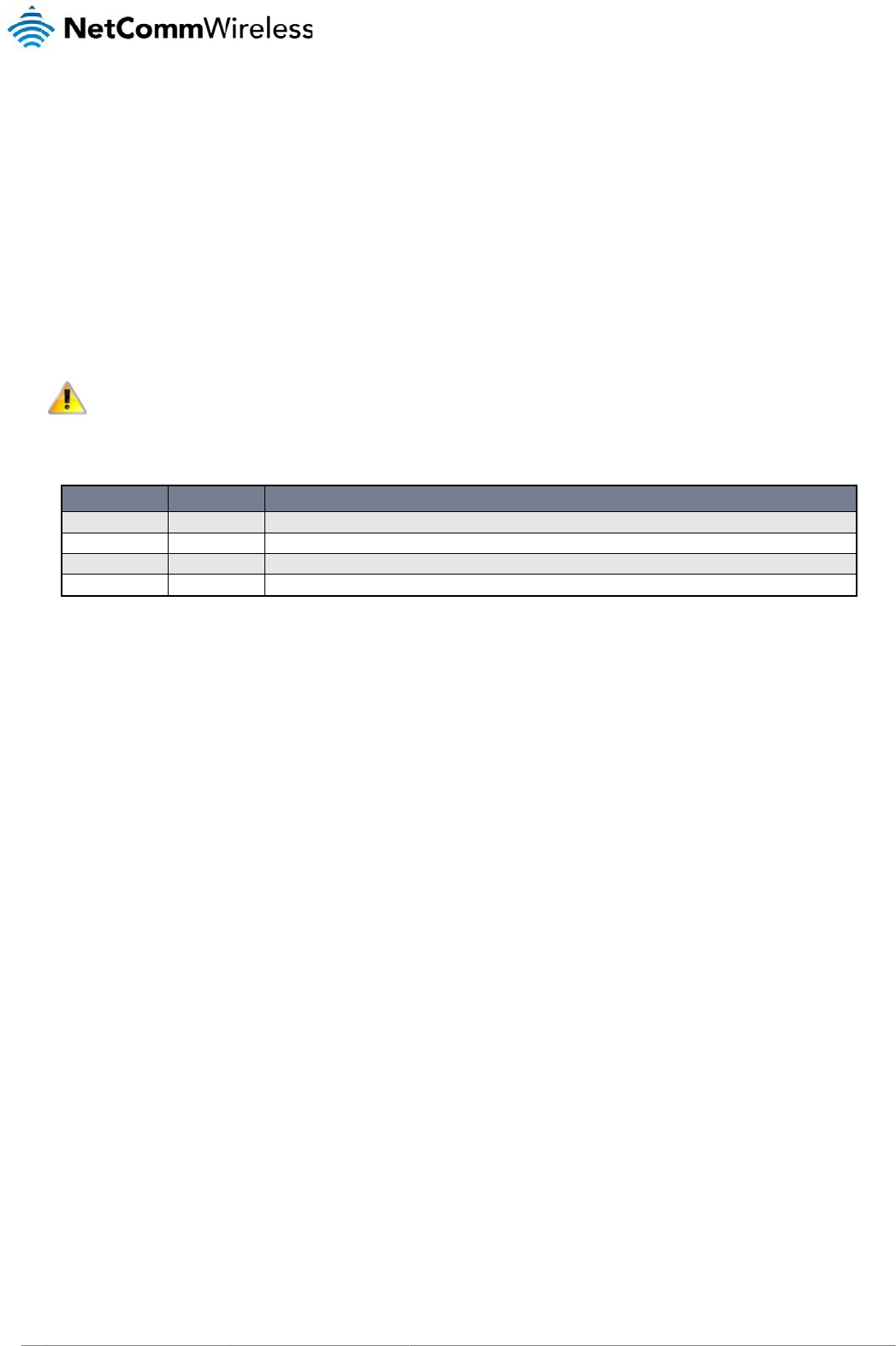
Mini USB Connector
The mini USB connector provides a USB based virtual COM port to facilitate communications to the NTC-3000 series in the event that a COM port fails. This is achieved through the
use of an SWI driver and an accompanying “3G Watcher” application. The connector uses a standard mini USB pin out configuration.
Pin: 1 5
Figure38‐TheMiniUSBConnector
PIN SIGNAL
1 VIN
2 D-
3 D+
4 N/C
5 GND
Table7‐MiniUSBConnectorPinOuts
www
.netcommwireless.com
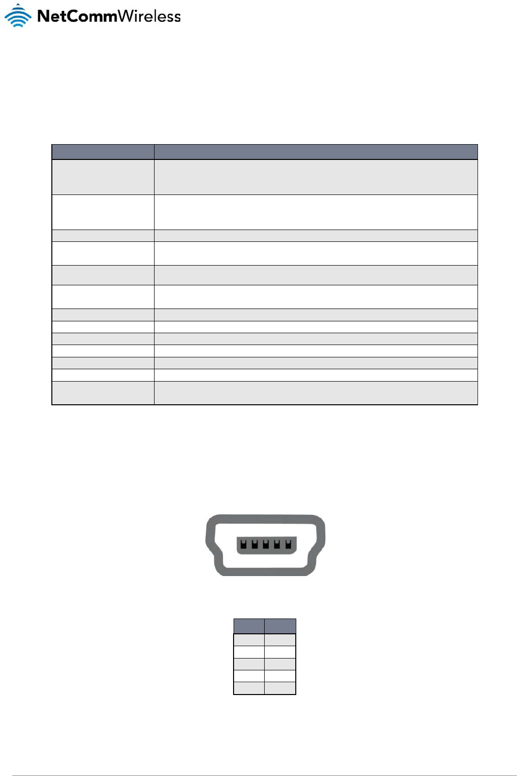
RJ-45 Co
n
The RJ-45 connect
o
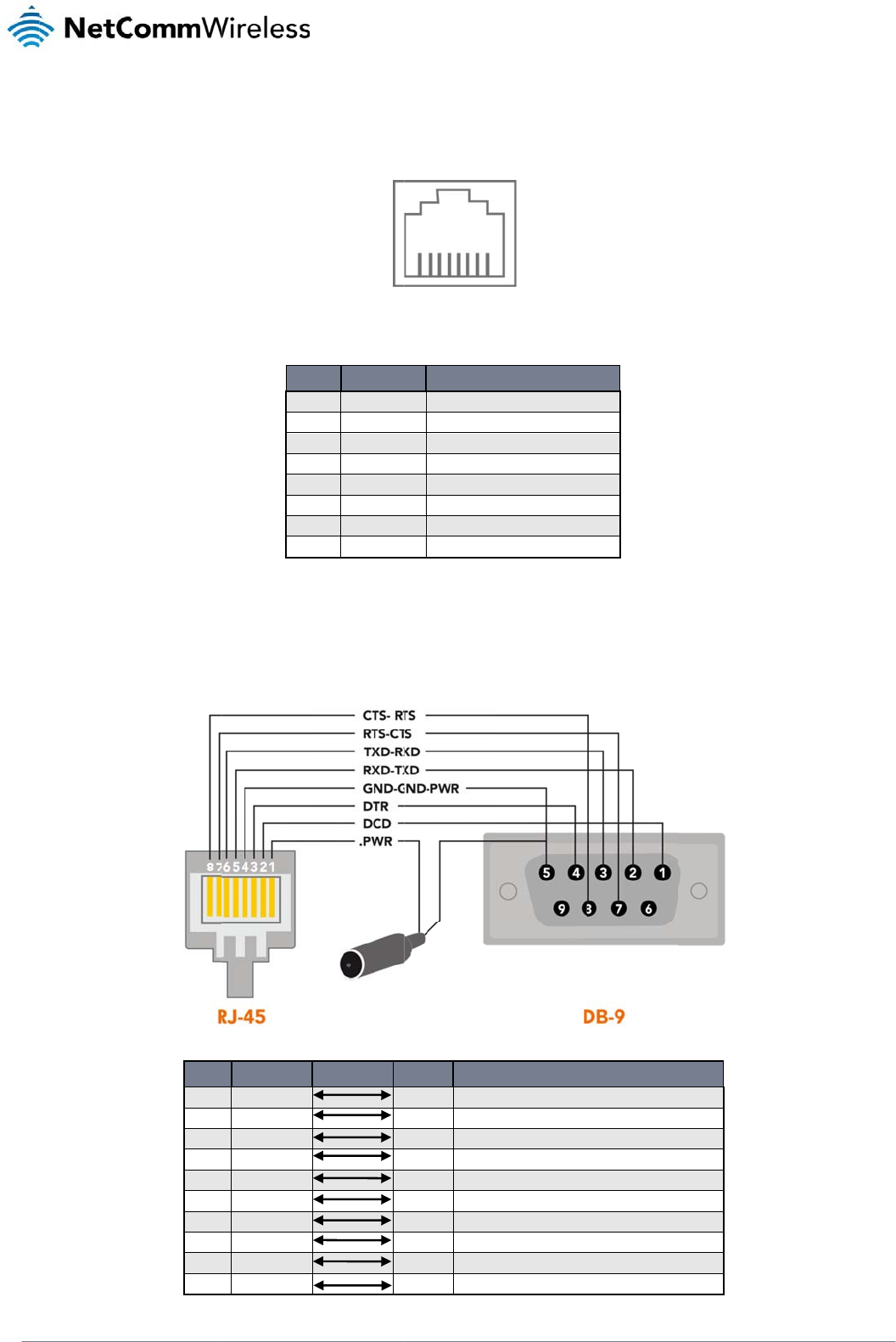
RJ-45 to
D
The following table
n
necto
r
o
r provides an interf
a
D
B9 Serial
/
displays the PIN out
DB9
1
2
3
4
5
6
7
8
9
-
a
ce for a serial data
c
Pi
n
PIN
1
2
3
4
5
6
7
8
/
Power Ad
a
configuration for the
SIGNAL
DCD
RXD
TXD
DTR
GND
DSR
RTS
CTS
RI
Power
c
onnection and for d
e
: 8 1
Figur
e
SIGNAL
VCC
DCD
DTR
GND
RXD
TXD
RTS
CTS
Ta
b
a
pter Cabl
RS-232 serial conn
e
Figure40‐RJ‐4
5
e
vice input power u
s
e
39‐TheRJ‐45Co
n
D
Input voltage 5V
D
Data Carrier Det
e
Data Terminal Re
a
Common Ground
Serial Data out
Serial Data in
Request/Ready t
o
Clear to Send
ble8‐RJ‐45Conne
l
e
e
ction cable that shi
p
5
toDB‐9Serial/Po
w
RJ45
2 Data Car
r
5 Serial Da
t
6 Serial Da
t
3 DTR
4 Common
- Not Use
d
7 Request t
8 Clear to
S
- Not Use
d
1 Red Wire
:
s
ing the pin layout sh
n
necto
r
D
ESCRIPTION
D
C - 36VDC
ct
a
dy
o
Send
ctorPinOuts
p
s with the NTC-300
0
w
erAdapterCable
DESC
R
r
ier Detect
t
a Out
t
a In
Ground GND (Power Gro
u
d
o Send (received by the N
S
end (transmitted by the N
T
d
:
VCC (Input voltage from
5
o
wn below.
series modems.
R
IPTION
nd)
T
C-3000)
T
C-3000)
5
V – 36VDC)
NT
C
NTC 30
0
C
-3000 Serie
s
0 Series –
M2M
Serial
s
Modem
49

NTC 3000 Series – M2M Serial Modem
50 www.netcommwireless.com
Table9‐RJ‐45toDB‐9Serial/PowerConnectorPinOuts
The NTC-3000 is a DCE (Data Circuit-Terminating Environment), so the RTS (Ready To Send) signal is received by the NTC-3000 and the CTS (Clear to Send) signal is transmitted
with flow controlled from both ends.
The DCD (Data Carrier Detect) line is permanently set to one state, i.e. in the high state at the connector, GND at the chip.
Electrical Specifications
A suitable power supply is available on request or via direct purchase from the NetComm Online shop. It is recommended that the NTC-3000 be powered using a 12VDC/1.5A power
supply.
Environmental Specifications / Tolerances
The industrial enclosure of the NTC-3000 Series makes it able to operate over a wide variety of temperatures from -20˚C ~ 50˚C.

www
.netcommwireless.com
Prod
The following secti
o
information.
Troubles
h
1) I am
u
V
V
V
P
2) I only
V
b
Please refer to the
NTC-3000 series.
3) The
N
V
P
4) The 3
V
c
Pleas
5) I am
r
V
6) I am
r
P
If you are still expe
r
http://support.netc
o
uct S
o
n provides some as
s
h
ooting
u
nable to send any
A
V
erify the NTC-3000
V
erify the LEDs on t
h
V
erify your terminal
p
P
ower cycle the NT
C
receive garbage te
x
V
erify that the COM
p
b
een changed.
AT Command refere
N
TC-3000 LEDs are
n
V
erify that the NTC-
3
P
ower cycle the NT
C
G LED is not switchi
n
V
erify that the NTC-
3
c
hecking a mobile t
e
e refer to the AT Co
m
r
eceiving an ‘ERROR
V
erify the AT comm
a
r
eceiving an ‘ERROR
P
lease refer to the e
r
r
iencing issues after
o
mmwireless.com
/
ervic
e
s
istance with issues
t
A
T commands to the
N
is connected to bot
h
h
e front of the NTC-3
0
p
rogram settings or
d
C
-3000 by removing
t
x
t when sending AT
c
p
ort parameters hav
e
nce document for m
o
n
ot lighting up
3
000 series is conne
c
C
-3000 by removing
t
n
g on
3
000 series has suffi
c
e
lephone for availabl
e
m
mand reference do
c
’ response from the
N
a
nd you are utilising
h
(##)’ response from
r
ror codes in the AT
C
performing the abov
e
e
an
d
t
hat may be encount
N
TC-3000
h
the power supply a
n
0
00 are illuminated.
d
evice is set to use t
h
he power supply for
c
ommands to the NT
C
e
not changed since
o
re information on e
n
c
ted to an appropriat
e
he power supply for
c
ient 3G signal stren
g
e
3G coverage.
c
ument for more info
N
TC-3000
h
as the correct synta
x
the NTC-3000 with
a
C
ommand manual w
h
e
checks, please co
n
d
Sup
p
t
ered when using the
n
d an appropriate C
O
h
e appropriate COM
15 seconds and the
n
C
-3000
the NTC-3000 serie
s
n
abling remote acce
s
e power supply and
15 seconds and the
n
g
th to connect by ch
e
rmation on signal str
x specified.
a
n error code that I d
h
ich can be found o
n
n
tact NetComm Tec
h
p
ort
NTC-3000 series as
O
M port.
port.
n
reconnect it.
s
was initially connec
s
s to the
that an active 3G SI
M
n
reconnect it.
e
cking the available
s
ength.
o
n’t understand
n
the Sierra Wireless
h
nical Support by goi
well as providing w
e
t
ed. Garbage text us
M
has been inserted.
s
ignal strength via ei
t
W
ebsite to learn the
ng to:
NT
C
NTC 30
0
e
b based links for pr
o
s
ually indicates that t
h
ther the appropriate
meaning of the Res
u
C
-3000 Serie
s
0 Series –
M2M
Serial
o
duct specific
h
e port speed has
AT command or by
u
lt codes.
s
Modem
51

NTC
52
3000 Series – M2M S
Web Bas
e
The following refer
e
http://www.netcom
m
U
Q
P
FAQs
Q: Is the
A: The
N
Thes
e
functi
o
Q: What
A: The
N
Gene
Q: Does
A: The
m
Q: Can t
h
A: No. T
h
Q: Why
c
A: The
N
Pleas
e
erial Modem
e
d Produc
t
e
nce information is al
m
wireless.com/prod
u
U
ser Manual
Q
uick Start Guide
P
roduct Specificatio
n
NTC-3000 series a
3
N
TC-3000 series is a
b
Creati
n
Creati
n
Creati
n
Creati
n
Conne
c
Conne
c
Email
s
Sendin
e
functions are supp
o
o
ns.
are the port settings
N
TC-3000 series use
s
rally, a port speed o
f
the NTC-3000 Serie
s
m
odem inside the NT
C
h
e mini USB port be
h
e mini USB port re
q
c
an’t I connect an Et
h
N
TC-3000 series use
s
e
refer to the RJ-45
p
t
Referenc
e
so available for the
N
u
ct/m2m/ntc-3000
n
Shee
t
3
G serial modem?
b
le to operate as a 3
G
n
g TCP serve
r
n
g UDP sockets / TC
P
n
g a PING session
n
g a FTP session (up
l
c
t to remote SMTP s
e
c
t to remote HTTP s
e
s
ending / receiving
g an MMS with one
o
o
rted in Sierra Wirele
s
required for the NT
C
s
auto-bauding to de
t
f
115200, 8 data bits
,
s
support circuit and
C
-3000 series supp
o
used to connect to l
e
q
uires Windows XP S
P
h
ernet (RJ-45) cable
s
a serial connection
p
ort pin out diagram i
e
s
N
TC-3000 Series fro
m
G
serial modem, ho
w
P
clients and TCP se
r
oad and download f
i
e
rve
r
e
rve
r
o
r multiple recipients
s
s’s WIPSOFT. Refe
r
C
-3000 Series?
t
ermine the current
c
1 stop bit, no parity
packet switched da
t
o
rts only Packet Swit
c
e
gacy devices?
P
3, Windows Vista S
P
to the NTC-3000 Se
r
through a modified
R
n
the Technical Data
m
the NetComm Sup
p
w
ever it is also so mu
c
rve
r
iles)
r
to the Sierra Wirele
s
c
ommunication port
s
and hardware flow
c
t
a?
c
hed communication
P
2, Windows 7 SP1
o
r
ies?
R
J-45 port utilising s
o
a
chapter for more in
f
p
ort website at
c
h more. It is also a
b
s
s Developer Zone t
o
s
ettings. This occurs
c
ontrol should be fin
e
s
methods.
o
r highe
r
or Mac OS
o
me pins from this to
f
ormation.
le to perform the foll
o
obtain the latest ve
r
w
hen the first A or A
T
e
.
1
0.5.8 or higher to in
provide power. It is
n
o
wing functions:
r
sion of the devkit to
T
is sent to the NTC-
3
n
stall and use.
not suitable for an E
t
www.netcommwirele
s
p
erform these
3
000 series.
t
hernet connection.
s
s.com

NTC-3000 Series
www.netcommwireless.com
NTC 3000 Series –
M2M
Serial Modem
53
Appendix A: Tables
Table 1 - Document Revision History ..................................................................................................................................................................................... 3
Table 2 - LED Indicators ........................................................................................................................................................................................................ 8
Table 3 - Device Dimensions ................................................................................................................................................................................................. 8
Table 4 - Mounting Bracket Dimensions ................................................................................................................................................................................ 8
Table 5 - Integrated Devices .................................................................................................................................................................................................. 9
Table 6 - Technical Specifications for the NTC-3000 Series ............................................................................................................................................... 48
Table 7 - Mini USB Connector Pin Outs ............................................................................................................................................................................... 48
Table 8 - RJ-45 Connector Pin Outs .................................................................................................................................................................................... 49
Table 9 - RJ-45 to DB-9 Serial/Power Connector Pin Outs .................................................................................................................................................. 50

NTC 3000 Series – M2M Serial Modem
54 www.netcommwireless.com
Safety and product care
RF Exposure
Your device contains a transmitter and a receiver. When it is on, it receives and transmits RF energy. When you communicate with your device, the system handling your connection
controls the power level at which your device transmits.
This device meets the government’s requirements for exposure to radio waves.
This device is designed and manufactured not to exceed the emission limits for exposure to radio frequency (RF) energy set by the Federal Communications Commission of the U.S.
Government.
This equipment complies with radio frequency (RF) exposure limits adopted by the Federal Communications Commission for an uncontrolled environment. This equipment should be
installed and operated with minimum distance 20 cm between the radiator & your body.
External antenna
Any optional external antenna used for this transmitter must be installed to provide a separation distance of at least 20 cm from all persons and must not be co-located or operated in
conjunction with any other antenna or transmitter. Please consult the health and safety guide of the chosen antenna for specific body separation guidelines as a greater distance of
separation may be required for high-gain antennas.
Any external antenna gain must meet RF exposure and maximum radiated output power limits of the applicable rule section. The maximum antenna gain for this device as reported to
the FCC is: 1dBi(850MHz) and 1dBi(1900MHz).
FCC Statement
FCC compliance
Federal Communications Commission Notice (United States): Before a wireless device model is available for sale to the public, it must be tested and certified to the FCC that it does
not exceed the limit established by the government-adopted requirement for safe exposure.
FCC regulations
This device complies with part 15 of the FCC Rules. Operation is subject to the following two conditions: (1) This device may not cause harmful interference, and (2) this device must
accept any interference received, including interference that may cause undesired operation.
This device has been tested and found to comply with the limits for a Class B digital device, pursuant to Part 15 of the FCC Rules. These limits are designed to provide reasonable
protection against harmful interference in a residential installation. This equipment generates, uses and can radiate radio frequency energy and, if not installed and used in
accordance with the instructions, may cause harmful interference to radio communications. However, there is no guarantee that interference will not occur in a particular installation. If
this equipment does cause harmful interference to radio or television reception, which can be determined by turning the equipment off and on, the user is encouraged to try to correct
the interference by one or more of the following measures:
Reorientate or relocate the receiving antenna.
Increase the separation between the equipment and receiver.
Connect the equipment into an outlet on a circuit different from that to which the receiver is connected.
Consult the dealer or an experienced radio/TV technician for help.
Changes or modifications not expressly approved by the party responsible for compliance could void the user‘s authority to operate the equipment.

NTC-3000 Series
www.netcommwireless.com
NTC 3000 Series –
M2M
Serial Modem
55
IC regulations
This device complies with Industry Canada licence-exempt RSS standard(s). Operation is subject to the following two conditions:
(1) this device may not cause interference, and
(2) this device must accept any interference, including interference that may cause undesired operation of the device.
Le présent appareil est conforme aux CNR d’Industrie Canada applicables aux appareils radio exempts de licence. L’exploitation est autorisée aux deux conditions suivantes:
(1) l’appareil ne doit pas produire de brouillage, et
(2) l’utilisateur de l’appareil doit accepter tout brouillage radioélectrique subi, même si le brouillage est susceptible d’en compromettre le fonctionnement.”
This Class B digital apparatus complies with Canadian CAN ICES-3 (B)/NMB-3(B).
Cet appareil numérique de la classe B est conforme à la norme NMB-003 du Canada.
IMPORTANT NOTE:
IC radiation exposure statement:
This equipment complies with IC RSS-102 radiation exposure limits set forth for an uncontrolled environment. This equipment should be installed and operated with minimum distance
20cm between the radiator and users body.
Electrical safety
Accessories
Only use approved accessories.
Do not connect with incompatible products or accessories.
Connection to a car
Seek professional advice when connecting a device interface to the vehicle electrical system.
Distraction
Operating machinery
Full attention must be given to operating the machinery in order to reduce the risk of an accident.

NTC 3000 Series – M2M Serial Modem
56 www.netcommwireless.com
Product handling
You alone are responsible for how you use your device and any consequences of its use.
You must always switch off your device wherever the use of a mobile phone is prohibited. Do not use the device without the clip-on covers attached, and do not remove or change the
covers while using the device. Use of your device is subject to safety measures designed to protect users and their environment.
Always treat your device and its accessories with care and keep it in a clean and dust-free place.
Do not expose your device or its accessories to open flames or lit tobacco products.
Do not expose your device or its accessories to liquid, moisture or high humidity.
Do not drop, throw or try to bend your device or its accessories.
Do not use harsh chemicals, cleaning solvents, or aerosols to clean the device or its accessories.
Do not paint your device or its accessories.
Do not attempt to disassemble your device or its accessories, only authorised personnel must do so.
Do not use or install this product in extremely hot or cold areas. Ensure that the device is installed in an area where the temperature is within the supported operating temperature
range (-20°C to 70°C)
Do not use your device in an enclosed environment or where heat dissipation is poor. Prolonged use in such space may cause excessive heat and raise ambient temperature, which
will lead to automatic shutdown of your device or the disconnection of the mobile network connection for your safety. To use your device normally again after such shutdown, cool it in
a well-ventilated place before turning it on.
Please check local regulations for disposal of electronic products.
Do not operate the device where ventilation is restricted
Installation and configuration should be performed by trained personnel only.
Do not use or install this product near water to avoid fire or shock hazard. Avoid exposing the equipment to rain or damp areas.
Arrange power and Ethernet cables in a manner such that they are not likely to be stepped on or have items placed on them.
Ensure that the voltage and rated current of the power source match the requirements of the device. Do not connect the device to an inappropriate power source.
Small children
Do not leave your device and its accessories within the reach of small children or allow them to play with it.
They could hurt themselves or others, or could accidentally damage the device.
Your device contains small parts with sharp edges that may cause an injury or which could become detached and create a choking hazard.
Emergency situations
This device, like any wireless device, operates using radio signals, which cannot guarantee connection in all conditions. Therefore, you must never rely solely on any wireless device
for emergency communications.
Device heating
Your device may become warm during normal use.
Faulty and damaged products
Do not attempt to disassemble the device or its accessories.
Only qualified personnel must service or repair the device or its accessories.
If your device or its accessories have been submerged in water punctured or subjected to a severe fall, do not use until they have been checked at an authorised service centre.
Interference
Care must be taken when using the device in close proximity to personal medical devices, such as pacemakers and hearing aids.
Pacemakers
Pacemaker manufacturers recommend that a minimum separation of 15cm be maintained between a device and a pacemaker to avoid potential interference with the pacemaker.

NTC-3000 Series
www.netcommwireless.com
NTC 3000 Series –
M2M
Serial Modem
57
Hearing aids
People with hearing aids or other cochlear implants may experience interfering noises when using wireless devices or when one is nearby.
The level of interference will depend on the type of hearing device and the distance from the interference source, increasing the separation between them may reduce the interference.
You may also consult your hearing aid manufacturer to discuss alternatives.
Medical devices
Please consult your doctor and the device manufacturer to determine if operation of your device may interfere with the operation of your medical device.
Hospitals
Switch off your wireless device when requested to do so in hospitals, clinics or health care facilities. These requests are designed to prevent possible interference with sensitive
medical equipment.
Interference in cars
Please note that because of possible interference to electronic equipment, some vehicle manufacturers forbid the use of devices in their vehicles unless an external antenna is
included in the installation.
Explosive environments
Petrol stations and explosive atmospheres
In locations with potentially explosive atmospheres, obey all posted signs to turn off wireless devices such as your device or other radio equipment.
Areas with potentially explosive atmospheres include fuelling areas, below decks on boats, fuel or chemical transfer or storage facilities, areas where the air contains chemicals or
particles, such as grain, dust, or metal powders.
Blasting caps and areas
Turn off your device or wireless device when in a blasting area or in areas posted turn off “two-way radios” or “electronic devices” to avoid interfering with blasting operations.

NTC 3000 Series – M2M Serial Modem
58 www.netcommwireless.com
Legal and Regulatory
Intellectual Property Rights
All intellectual property rights (including copyright and trade mark rights) subsisting in, relating to or arising out this Manual are owned by and vested in NetComm Wireless Limited
(ACN 002490486) (NetComm Wireless Limited) (or its licensors). This Manual does not transfer any right, title or interest in NetComm Wireless Limited’s (or its licensors’) intellectual
property rights to you.
You are permitted to use this Manual for the sole purpose of using the NetComm Wireless product to which it relates. Otherwise no part of this Manual may be reproduced, stored in a
retrieval system or transmitted in any form, by any means, be it electronic, mechanical, recording or otherwise, without the prior written permission of NetComm Wireless Limited.
NetComm and NetComm Wireless is a trademark of NetComm Wireless Limited. All other trademarks are acknowledged to be the property of their respective owners.
Customer Information
The Australian Communications & Media Authority (ACMA) requires you to be aware of the following information and warnings:
1. This unit shall be connected to the Telecommunication Network through a line cord which meets the requirements of the AS/CA S008-2011 Standard.
2. This equipment has been tested and found to comply with the Standards for C-Tick and or A-Tick as set by the ACMA. These standards are designed to provide
reasonable protection against harmful interference in a residential installation. This equipment generates, uses, and can radiate radio noise and, if not installed and used
in accordance with the instructions detailed within this manual, may cause interference to radio communications. However, there is no guarantee that interference will not
occur with the installation of this product in your home or office. If this equipment does cause some degree of interference to radio or television reception, which can be
determined by turning the equipment off and on, we encourage the user to try to correct the interference by one or more of the following measures:
a) Change the direction or relocate the receiving antenna.
b) Increase the separation between this equipment and the receiver.
c) Connect the equipment to an alternate power outlet on a different power circuit from that to which the receiver/TV is connected.
d) Consult an experienced radio/TV technician for help.
3. The power supply that is provided with this unit is only intended for use with this product. Do not use this power supply with any other product or do not use any other
power supply that is not approved for use with this product by NetComm Wireless Limited. Failure to do so may cause damage to this product, fire or result in personal
injury.
Consumer Protection Laws
Australian and New Zealand consumer law in certain circumstances implies mandatory guarantees, conditions and warranties which cannot be excluded by NetComm Wireless
Limited and legislation of another country's Government may have a similar effect (together these are the Consumer Protection Laws). Any warranty or representation provided by
NetComm Wireless Limited is in addition to, and not in replacement of, your rights under such Consumer Protection Laws.
If you purchased our goods in Australia and you are a consumer, you are entitled to a replacement or refund for a major failure and for compensation for any other reasonably
foreseeable loss or damage. You are also entitled to have the goods repaired or replaced if the goods fail to be of acceptable quality and the failure does not amount to a major failure.
If you purchased our goods in New Zealand and are a consumer you will also be entitled to similar statutory guarantees.

NTC-3000 Series
www.netcommwireless.com
NTC 3000 Series –
M2M
Serial Modem
59
Product Warranty
All NetComm Wireless products have a standard two (2) year warranty from date of purchase (Product Warranty). For all Product Warranty claims you will require proof of purchase.
All Product Warranties are in addition to your rights and remedies under applicable Consumer Protection Laws which cannot be excluded (see Section 3 above).
Subject to your rights and remedies under applicable Consumer Protection Laws which cannot be excluded (see Section 3 above), the Product Warranty is granted on the following
conditions:
1. The Product Warranty extends to the original purchaser (you / the customer) and is not transferable;
2. The Product Warranty shall not apply to software programs, batteries, power supplies, cables or other accessories supplied in or with the product;
3. The customer complies with all of the terms of any relevant agreement with NetComm Wireless Limited and any other reasonable requirements of NetComm
Wireless Limited including producing such evidence of purchase as NetComm may require;
4. The cost of transporting product to and from NetComm Wireless Limited’s nominated premises is your responsibility;
5. NetComm Wireless Limited does not have any liability or responsibility under the Product Warranty where any cost, loss, injury or damage of any kind, whether
direct, indirect, consequential, incidental or otherwise arises out of events beyond NetComm Wireless Limited’s reasonable control. This includes but is not limited
to: acts of God, war, riot, embargoes, acts of civil or military authorities, fire, floods, electricity outages, lightning, power surges, or shortages of materials or labour;
and
6. The customer is responsible for the security of their computer and network at all times. Security features may be disabled within the factory default settings.
NetComm Wireless Limited recommends that you enable these features to enhance your security.
Subject to your rights and remedies under applicable Consumer Protection Laws which cannot be excluded (see Section 3 above), the Product Warranty is automatically voided if:
1. You, or someone else, use the product, or attempt to use it, other than as specified by NetComm Wireless Limited;
2. The fault or defect in your product is the result of a voltage surge subjected to the product either by the way of power supply or communication line, whether
caused by thunderstorm activity or any other cause(s);
3. The fault is the result of accidental damage or damage in transit, including but not limited to liquid spillage;
4. Your product has been used for any purposes other than that for which it is sold, or in any way other than in strict accordance with the user manual supplied;
5. Your product has been repaired or modified or attempted to be repaired or modified, other than by a qualified person at a service centre authorised by NetComm
Wireless Limited; or
6. The serial number has been defaced or altered in any way or if the serial number plate has been removed.
Limitation of Liability
This clause does not apply to New Zealand consumers. Subject to your rights and remedies under applicable Consumer Protection Laws which cannot be excluded (see Section 3
above), NetComm Wireless Limited accepts no liability or responsibility, for consequences arising from the use of this product. NetComm Wireless Limited reserves the right to change
the specifications and operating details of this product without notice.
If any law implies a guarantee, condition or warranty in respect of goods or services supplied, and NetComm Wireless Limited’s liability for breach of that condition or warranty may
not be excluded but may be limited, then subject to your rights and remedies under any applicable Consumer Protection Laws which cannot be excluded, NetComm Wireless
Limited’s liability for any breach of that guarantee, condition or warranty is limited to:
(i) in the case of a supply of goods, NetComm Wireless Limited doing any one or more of the following: replacing the goods or supplying equivalent goods; repairing
the goods; paying the cost of replacing the goods or of acquiring equivalent goods; or paying the cost of having the goods repaired; or
(ii) in the case of a supply of services, NetComm Wireless Limited doing either or both of the following: supplying the services again; or paying the cost of having the
services supplied again.
To the extent NetComm is unable to limit its liability as set out above, NetComm Wireless Limited limits its liability to the extent such liability is lawfully able to be limited.
Contact
Address: NETCOMM WIRELESS LIMITED, Level 2, 18-20 Orion Road, Lane Cove NSW 2066 Sydney, Australia
ABN: 85 002 490 486
Website: http://www.netcommwireless.com/

NTC 3000 Series – M2M Serial Modem
60 www.netcommwireless.com
Phone: +61(0)2 9424 2070
Fax: +61(0)2 9424 2010
Email: sales@netcommwireless.com, technicalsupport@netcommwireless.com