NetComm Wireless NTC6908 M2M ROUTER User Manual
NetComm Wireless Limited M2M ROUTER Users Manual
UserManual.wiki
>
NetComm Wireless
>
NTC6908 User Manual
Users Manual
Navigation menu
Upload a User Manual
Namespaces
Wiki Guide
HTML
PDF
Info
Views
User Manual
Discussion / Help
Navigation


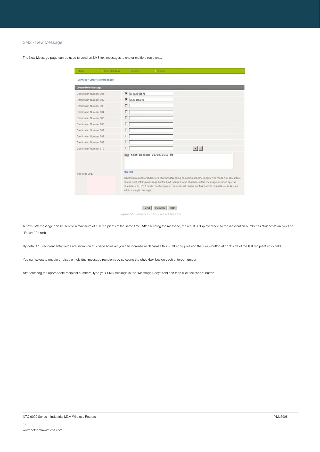
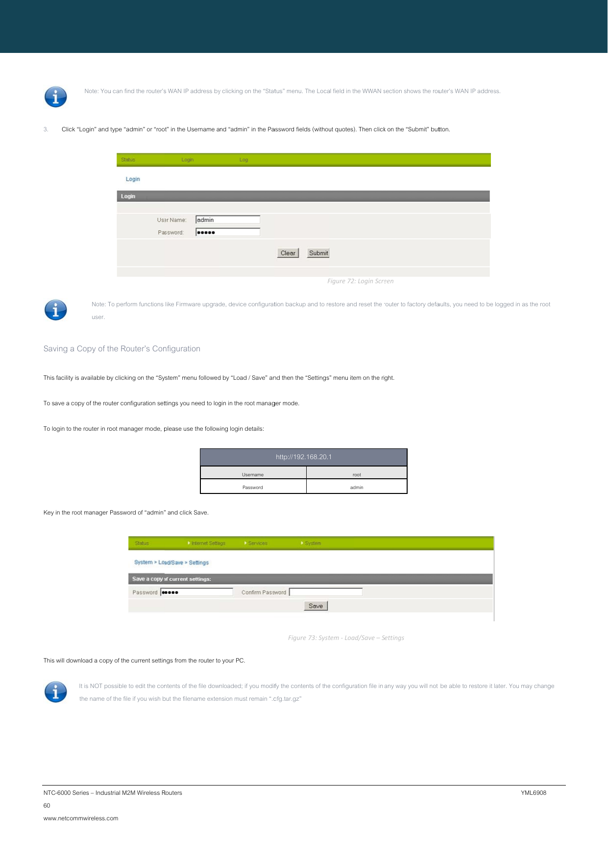
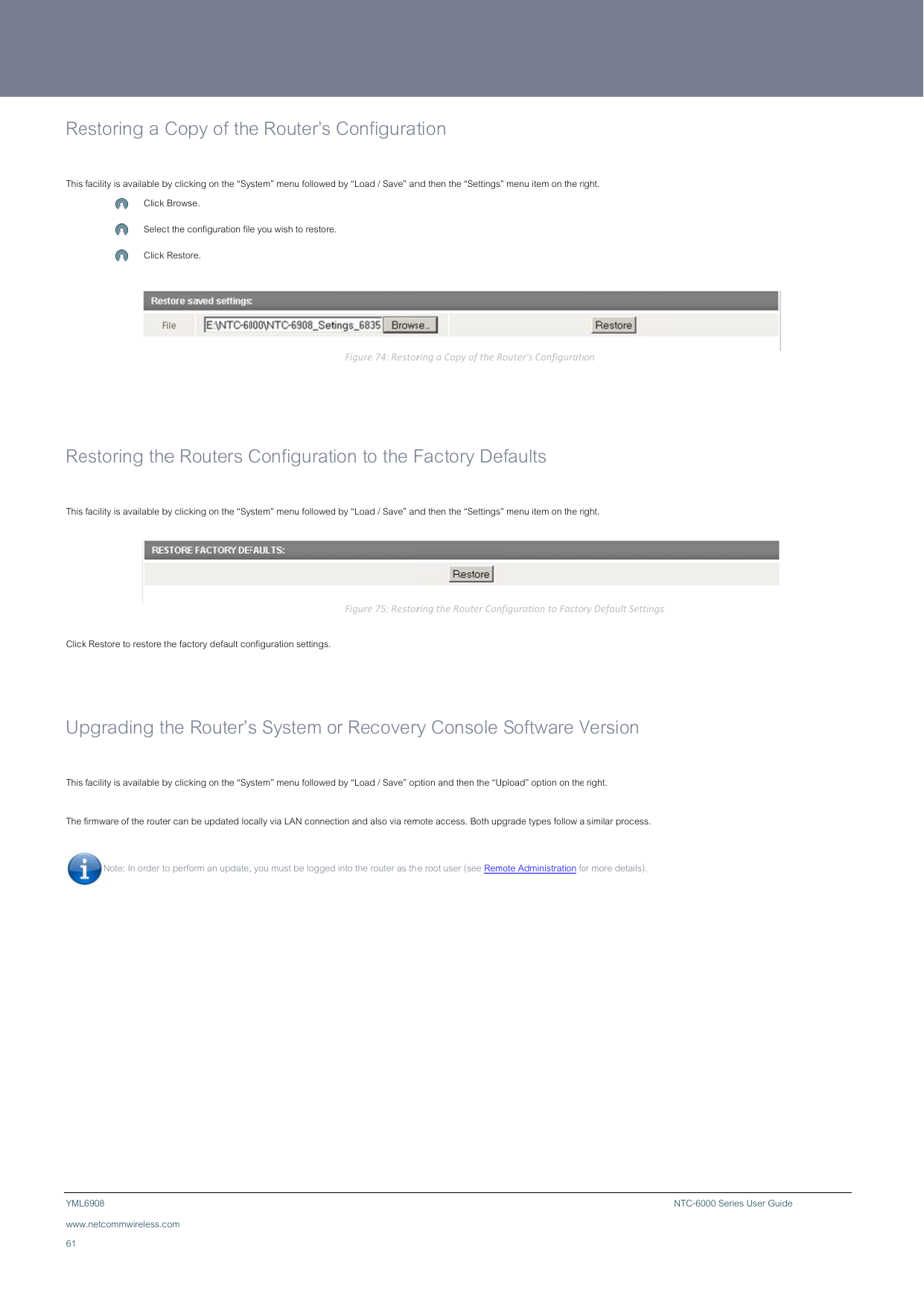
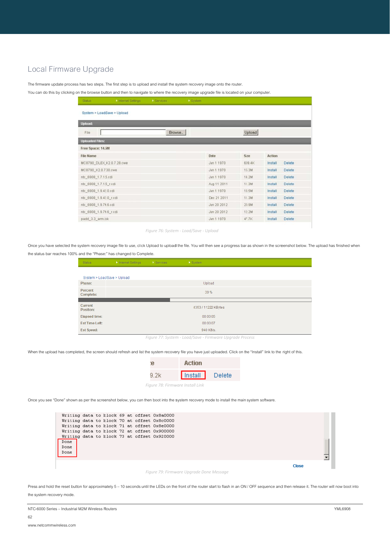
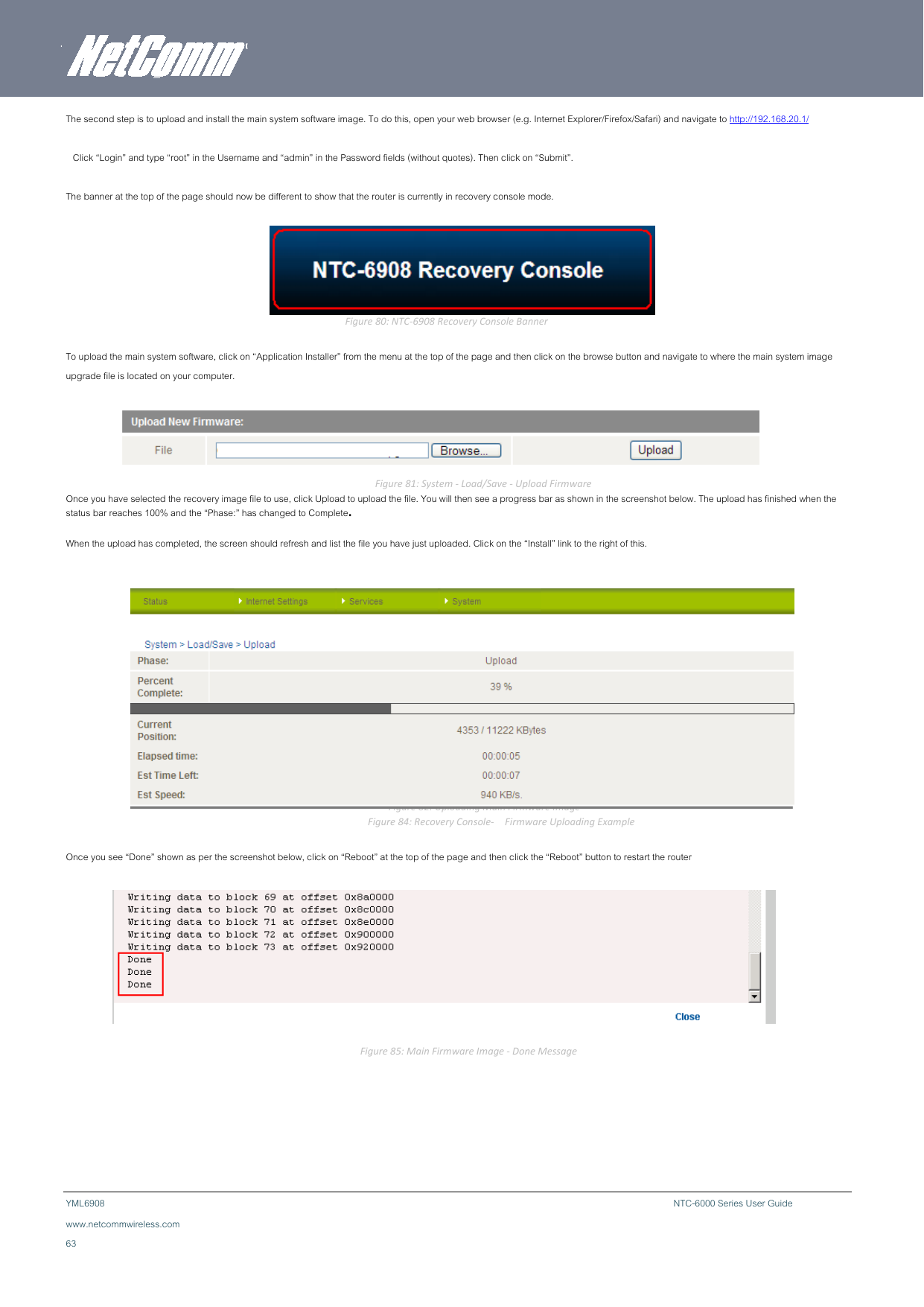
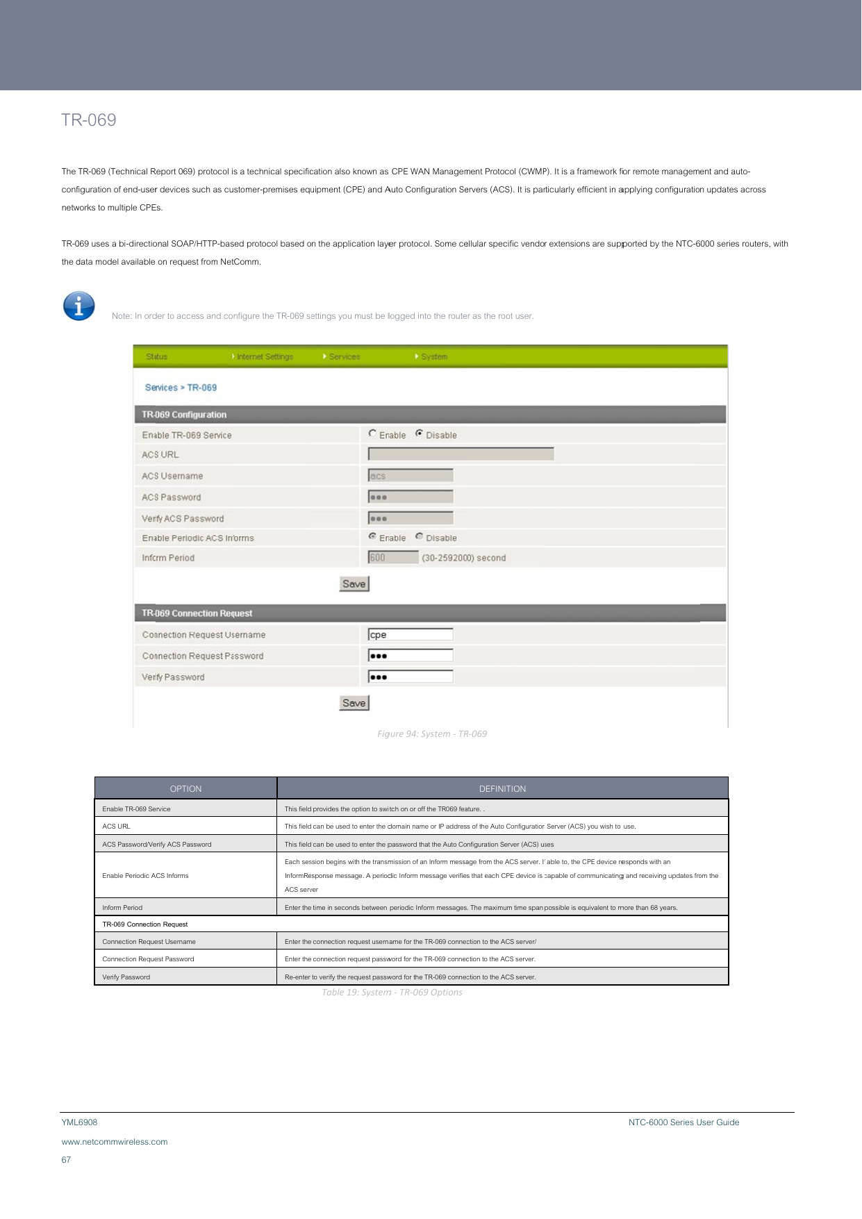
![NTC66 www Sy The TCP conf C-6000 Series – Indus w.netcommwireless.cystem ConfSystem configuration Keepalive can be usfirm the network connstrial M2M Wireless R com figuration n page is used to spesed to ensure the WWnection is still valid. IP KeKeKeKeDiDiRouters ecify an external syslWAN connection doeOPTION / Hostname [:PORT] eepalive eepalive Time eepalive Interval eepalive Probes agnostic Configuration agnostic TCP Port og server and the TCs not become disconFigure93:System The inforSeleThe sentThe The Table18:System NETCOMMCP Keepalive settingsnnect due to inactivitmConfigurationPag IP address and port of thermation sent to. ect to enable or disable the interval between the last pt. time between subsequent number of TCP Keepalive Select this optionEnter the port numbmConfigurationSett CALLDIRECT™ s. y by periodically sengeDEFINITION e external syslog server youe TCP Keepalive function. packet sent and the first TCt TCP Keepalive packets. packets to send. n to enable diagnostic conber you wish the diagnostictings SERIES – NTCding a ping request u would like logging CP keepalive packet being figuration mode. information sent to. C-6000 Seriemessage to a WAN I YML6908 sP address or domain n to](https://usermanual.wiki/NetComm-Wireless/NTC6908/User-Guide-1827390-Page-66.png)