NetComm Wireless NTC6908 M2M ROUTER User Manual
NetComm Wireless Limited M2M ROUTER Users Manual
Users Manual
N
E
P
E
TCOMM
C
Rout
P
refa
c
C
ALLDIRE
C
c
e
C
T
SERIES
NETCOMM CALLDIRECT™
SERIES – NT
C
U
S
C
-6000 Serie
S
ER
G
NTC-
s
G
UID
6
000 Series
E
NT
C
2
ww
w
This
tele
c
If yo
For
p
I
m
With
Co
p
Cop
All ri
The
writt
e
Sa
v
Wh
e
The
elec
Ple
a
C
-6000 Series – Indu
s
w
.netcommwireless.c
manual provides inf
o
c
ommunications ter
m
u find the product to
p
roduct updates, ne
w
m
portant S
a
reference to unpac
k
Do n
o
expo
s
Do n
o
In ad
d
To sa
f
WARN
p
yright
y
right©2011 NetCo
m
ghts reserved.
information containe
e
n consent of NetCo
NOTE: T
h
v
e
Our Envir
o
n
e
n this equipment ha
s
cardboard box, the
p
tronic equipment alo
se be responsible a
n
s
trial M2M Wireless
R
c
om
o
rmation relating to t
m
inology and concep
be broken or malfu
n
w
product releases,
m
a
fety Instru
k
ing, installation, use
o
t use or install this p
s
e the equipment to
r
o
t connect the powe
r
d
ition, do not walk o
n
f
eguard the equipm
e
ING: Disconnect the
m
m Wireless Limited.
d herein is proprieta
r
mm Wireless Limite
d
h
is document is subj
e
n
ment
s
reached the end o
f
p
lastic contained in t
o
ng with your househ
o
n
d protect our enviro
R
outers
he installation, oper
a
ts.
n
ctioning, please con
m
anual revisions, or
s
ctions
and maintenance o
f
roduct near water to
r
ain or damp areas (
e
r
supply cord on elev
n
, step on or mistreat
e
nt against overheati
n
power line from the
d
r
y to NetComm Wirel
d
.
e
ct to change withou
t
f
its useful life, it mus
t
he packaging, and t
h
o
ld waste. You may
b
nment.
DOCUMENT
1.0
1.2
2.1
2.2
2.3
a
tion, and application
tact technical suppo
s
oftware upgrades,
p
your elect
r
onic devi
c
avoid fire or shock h
e
.g. a wet basement
)
ated surfaces. Allow
the cord.
n
g, make sure that a
l
d
evice before servic
i
ess Limited. No part
t
notice.
t
be taken to a recyc
l
h
e parts that make u
p
b
e subject to penalti
e
VERSION
D
J
No
v
Fe
J
J
Table1:NTC‐60
0
NETCOMM
n
of this device. The i
o
rt for immediate ser
v
p
lease visit our web
s
ce, the following ba
s
h
azard. For example,
)
.
w
it to lie freely. There
ll openings in the un
i
ing.
of this document m
a
ling center and proc
e
p this router can be
r
e
s or sanctions und
e
DATE
J
une 2010
v
ember 2010
e
bruary 2011
A
dded
J
une 2011
A
dded
S
J
une 2012
A
d
d
0
0SeriesUserMan
CALLDIRECT™
ndividual reading thi
s
v
ice by email at Tech
s
ite at
www.netcom
m
s
ic guidelines are re
c
near a bathtub, kitc
h
should be no obstru
i
t that offer exposure
a
y be translated, tran
e
ssed separately fro
m
r
ecycled in accorda
n
e
r the law. Instead as
CHANGEH
Internal Release Ver
s
Initial Public Releas
e
GPS and Modem configu
r
S
MS Tools configuration d
o
d
ed TR069 configuration s
e
ualDocumentHist
o
SERIES – NT
C
s
manual is presume
nical.Support@netc
o
wireless.com
ommended:
h
en sink, laundry tub
,
ctions in its path an
d
to air are unobstruc
t
s
cribed, reproduced
m
domestic waste.
n
ce with regionally e
s
k
for disposal instru
c
ISTORY
s
ion (FW 1.52)
e
(FW v1.57)
ation sections (FW v1.7.0)
o
cumentation (FW v1.7.1.5
)
e
ctions (FW v 1.9.79.6)
o
r
y
C
-6000 Serie
e
d to have a basic u
n
o
mmwireless.com
, or near a swimmin
g
d
no heavy items sh
o
t
ed.
d
, in any form, or by
a
s
tablished regulation
c
tions from your mun
i
)
YML6908
s
n
derstanding of
g
pool. Also, do not
o
uld be placed on th
e
a
ny means without p
r
s
. Never dispose of
t
cipal government.
e
cord.
r
ior
t
his

YML6908 NTC-6000 Series User Guide
www.netcommwireless.com
3
T
able
of
Contents
Int roduct ion . .. .. . .. .. .. . .. .. . .. .. . .. .. .. . .. .. . .. .. . .. .. .. . .. .. . .. .. .. . .. .. . .. .. . .. .. .. . .. .. . .. .. . .. .. .. . .. .. . .. .. .. . .. .. . .. .. . .. .. .. . .. .. . .......... 5
Overview ................................................................................................................................................................................................................................................................................................................................... 5
Features .................................................................................................................................................................................................................................................................................................................................... 6
Hardware Overview .. . .. .. .. . .. .. . .. .. .. . .. .. . .. .. . .. .. .. . .. .. . .. .. . .. .. .. . .. .. . .. .. .. . .. .. . .. .. . .. .. .. . .. .. . .. .. .. . .. .. . .. .. . .. .. .. . .. .. . .. .. . .. . . 7
LED Overview............................................................................................................................................................................................................................................................................................................................ 7
Overview of the Router Interfaces ............................................................................................................................................................................................................................................................................................ 8
Configuring your Rout er. .. ......... .. .. .. .. ......... .. .. .. ....... . . . . . . ....... . . . . . . ...... . . . . . . ...... . . . . . . . ...... . . . . . . ...... ....... . . . ..... . . . 10
Inserting the SIM Card ............................................................................................................................................................................................................................................................................................................ 10
Setting Up the Cellular Router ................................................................................................................................................................................................................................................................................................ 10
Preparing Your Computer ....................................................................................................................................................................................................................................................................................................... 12
Accessing the Router Web User Interface ............................................................................................................................................................................................................................................................................. 17
Unlocking the SIM Card .......................................................................................................................................................................................................................................................................................................... 18
Band / Provider Select ion . . ...... . . . . . . ....... . . . . . . ...... . . . . . . ...... . . . . . . . ...... . . . . . . ...... . . . . . . . ...... . . . . . . ...... . . . . . . . ..... . . . . ..... . . . 22
Locking To a Specific Band .................................................................................................................................................................................................................................................................................................... 22
Choosing Your Mobile Broadband Provider Manually ........................................................................................................................................................................................................................................................... 23
Establishing a Connection to a Cellular Network ................................................................................................................................................................................................................................................................... 24
Ethernet Related Commands .................................................................................................................................................................................................................................................................................................. 27
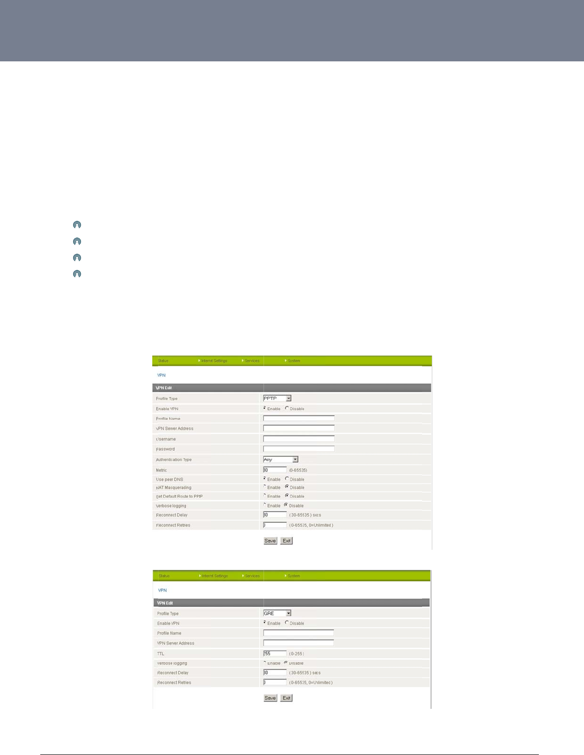
Virtual Private Networks .......................................................................................................................................................................................................................................................................................................... 29
Configuring a PPTP / GRE connection ................................................................................................................................................................................................................................................................................... 29
OpenVPN ................................................................................................................................................................................................................................................................................................................................ 31
IPSec 33
Routing Configuration ............................................................................................................................................................................................................................................................................................................. 35
How to Configure RIP .............................................................................................................................................................................................................................................................................................................. 36
How to Configure VRRP .......................................................................................................................................................................................................................................................................................................... 37
NAT configuration ................................................................................................................................................................................................................................................................................................................... 38
Services
Feat ur
es
..... . . . . . . ...... . . . . . . ..... . . . . . . . ..... . . . . . . ...... . . . . . . ...... . . . . . . ..... . . . . . . . ..... . . . . . . ...... . . . . . . ...... . . . . . . ..... . . . . .. . 39
Services Features ................................................................................................................................................................................................................................................................................................................... 40
GPS 45
SMS Tools ............................................................................................................................................................................................................................................................................................................................... 46
NSUpdate ................................................................................................................................................................................................................................................................................................................................ 57
PADD 錯誤! 尚未定義書籤。
System Features . ...... . . . . . . ....... . . . . . . ...... . . . . . . ...... . . . . . . . ...... . . . . . . ...... . . . . . . . ...... . . . . . . ...... . . . . . . . ...... . . . . . . ...... . . . . . . . ........... 58
Viewing the system log ........................................................................................................................................................................................................................................................................................................... 58
Remote Administration ............................................................................................................................................................................................................................................................................................................ 59
Restoring a Copy of the Router’s Configuration ..................................................................................................................................................................................................................................................................... 61
Remote Firmware Upgrade .................................................................................................................................................................................................................................................................................................... 64
Package Manager ................................................................................................................................................................................................................................................................................................................... 65
System Configuration .............................................................................................................................................................................................................................................................................................................. 66
TR-069 ........................................................................................................................ ............................................................................................................................................................................................................. 67
T
r
oubl eshoot ing
. . . . . . . . . . . . . . . . . . . . . . . . . . . . . . . . . . . . . . . . . . . . . . . . . . . . . . . . . . . . . . . . . . . . . . . . . . . . . . . . . . . . . . . . . . . . . . . . . . . . . . . . . . . . . . . . . . . . . . . . . . . . . . ...... 69
Common problems and solutions. .......................................................................................................................................................................................................................................................................................... 69
Spe cif icat io ns . . . ...... . . . . . . ...... . . . . . . . ...... . . . . . . ...... . . . . . . . ...... . . . . . . ...... . . . . . . ....... . . . . . . ...... . . . . . . ....... . . . ...................... 72
Hardware Specifications ......................................................................................................................................................................................................................................................................................................... 72
Legal & Regulat ory Inf ormat ion ....... . . . . . . ...... . . . . . . ....... . . . . . . ...... . . . . . . ....... . . . . . . ...... . . . . . . ....... . . . . . . ...... . . .. . . . ...... . . . .. 75
Intellectual Property Rights ..................................................................................................................................................................................................................................................................................................... 75
Customer Information .............................................................................................................................................................................................................................................................................................................. 75
Consumer Protection Laws ..................................................................................................................................................................................................................................................................................................... 75
Product Warranty .................................................................................................................................................................................................................................................................................................................... 76
Limitation of Liability ................................................................................................................................................................................................................................................................................................................ 76

NTC-6000 Series – Industrial M2M Wireless Routers YML6908
4
www.netcommwireless.com
NETCOMM CALLDIRECT™ SERIES – NTC-6000 Series
Cont act . . . . ...... . . . . . . ....... . . . . . . ...... . . . . . . ...... . . . . . . . ...... . . . . . . ...... . . . . . . . ...... . . . . . . ...... . . . . . . . ...... . . . . . . ... ...................... 78

YML6908 NTC-6000 Series User Guide
www.netcommwireless.com
5
Introduction
Thank you for purchasing an Industrial HSPA Cellular Network Router from NetComm. This manual illustrates how to set-up and configure your router appropriately for your chosen task. The
router is primarily managed and configured via a web browser. This manual will take you through the steps required to configure and use your unit correctly.
Additionally, the router may be configured via the serial (V.24) port using “AT” (V.250) commands. This method of operation is further detailed in the document: NTC-6000Series_V250 (AT)
Manual_V1-1-0.
Overview
An NTC-6000 series router allows you to build wide area networks utilizing the superior speeds supported by 3G UMTS networks. Employing an embedded 3G UMTS modem module the router
offers downlink speeds of up to 7.2Mbps and uplink speeds of up to 5.76Mbps
The NTC-6000 series provides the user a point-to-point or point-to-multi-point communications link in a single, compact and resilient unit.
As a fully featured cellular router, it supports a large number of communication interfaces and protocols to meet the demands of today’s telemetry and WAN applications.
Designed with remote installation in mind the NTC-6000 series supports multi-level system monitoring giving the user peace of mind the device will keep the lines of communication up and open.
In the event of system corruption, a built-in recovery mode provides the facility to re-install the system software to the router and resume normal operations quickly. Using the recovery console is
further detailed in the document NTC-6XXX Firmware Upgrade VX.X.X.pdf that is part of all NTC-6000 series firmware upgrade packs released, which are available for download in the support
section of our website at www.netcommwireless.com .

NTC-6000 Series – Industrial M2M Wireless Routers YML6908
6
www.netcommwireless.com
NETCOMM CALLDIRECT™ SERIES – NTC-6000 Series
Features
Intelligent industrial cellular router platform supporting various networks and service types UMTS/HSDPA/HSUPA & GSM/GPRS/EDGE
High-speed Atmel 400MHz ARM9-based Microcontroller.
Embedded Sierra HSPA modem module MC8790V (NTC-6908) or MC8792V (NTC-6909) with Qualcomm MSM6290 chipset.
Antenna diversity to improve fringe performance on global HSPA networks.
Wide area data access speeds in 3G mode up to 7.2Mbps in downlink (HSDPA category 8) and up to 5.76Mbps in uplink (HSUPA category 6).
Wide area data access speeds in 2G mode up to 236 kbps (EDGE multi slot class 12).
Rugged metal housing and temperature-hardened electronic components - extended operating temperature -30 to 70°C.
Wide input voltage range: 8 – 28 V DC. Suitable for diverse environments and applications.
Embedded Linux operating system allowing for the installation of custom applications.
Web user interface for easy centralized configuration and management from any computer or smartphone with multi-level administrator access.
10/100Base-TX port for Ethernet connections.
RS-232 port for connection to serial devices.
PAD mode via the serial port.
Integrated GPS for remote position tracking-location mapping via Google Maps.
VPN client for establishing a secure connection over public networks.
Supports SNMP with cellular specific MIB, PPPoE, MAC /NET address filtering,
DHCP/DHCP relay, Dynamic DNS and advanced routing RIP/VRRP
Supports NAT, Port forwarding and a DMZ Host
Configurable APN profiles (drop-down list)
Supports manual network scan
System monitoring, diagnostic log viewer.
Web user interface for easy centralized configuration and management from any PC or smart phone
Remote diagnostics, configuration and firmware update over the air (FOTA)
SMS client allowing advanced SMS diagnostics and command execution
Software Development Kit (SDK) for the creation of custom applications
Dual system management - recovery mode to restore router system software in the event of corruptions locally or remotely.
TR 069 functionality for ACS server management.
YML6908 NTC-6000 Series User Guide
www.netcommwireless.com
7
Hardware Overview
LED Overview
There are a total of five LED’s on the router.
Listed below are the specifications of the LED’s and their corresponding colours.
Figure1:NTC‐6000SeriesLEDs
LED DISPLAY DESCRIPTION
POWER (red) Solid ON The red Power LED indicates power has been applied to the router from the DC power input jack.
TX Rx (amber) Solid ON The amber LED will light upon data being sent to or received from the cellular network.
DCD (green) Solid ON The green Data Carrier Detect LED illuminates to indicate a data connection.
Service Type (green) The green LED will illuminate when cellular network coverage is detected.
Solid ON 3G: Indicates UMTS/HSPA available coverage
Flashing EDGE: Indicates EDGE available coverage
Off 2G: Indicates GSM/GPRS available coverage only.
RSSI (green)
This green LED shows Received Signal Strength. There are three possible states that the RSSI LED can operate in, based upon signal level.
Solid ON Strong: Indicates the RSSI level is -86dbm
Flashing Once a Second Medium: Indicates the RSSI level is -110dbm and -86dbm
Off Fair: Indicates the RSSI level is less than -110dbm
Table2:LEDDescriptions
NT
C
8
ww
w
O
v
C
-6000 Series – Indu
s
w
.netcommwireless.c
v
erview of
Main A
n
Receiv
e
Serial R
Indicat
o
Power
T
Reset B
Etherne
t
SIM Ca
r
s
trial M2M Wireless
R
c
om
the Route
r
FIELD
n
tenna Socket
e
Diversity Antenna Socket
S-232 Port
o
r LEDs
T
erminal Block
utton
t Port
r
d Reader
R
outers
r
Interface
s
s
Female SMA Connect
o
Female SMA Connect
o
For connecting to a te
Indicates the connecti
The screw terminal of
environments
Pressing this button f
o
After installing new fir
m
For direct connection
t
For insertion and rem
o
Table3:Router
I
NETCOMM
Figure
Figure3:
or
or
e
rminal using a DB9-F cabl
ion strength, service type,
the DC power plug and th
e
o
r 10 seconds will set the r
o
m
ware the router must be
r
to your devices through a
o
val of SIM card
I
nterfacePorts
CALLDIRECT™
2:RouterInterface
s
RouterInterfaces
–
DESCRIPTI
O
e
.
data traffic, data carrier c
o
e
wide input voltage rang
e
o
uter into recovery mode
w
r
eset to factory default sett
hub or network router
SERIES – NT
C
s
–LeftSideView
RightSideView
O
N
o
nnection and network con
of 8-28V DC simplify the i
n
w
here firmware or applicati
o
i
ngs before being reco
n
C
-6000 Serie
n
nection strength
nstallation in different indu
on packages can be uplo
a
n
figured.
YML6908
s
s
trial
a
ded.

YML6908 NTC-6000 Series User Guide
www.netcommwireless.com
9
NT
C
10
ww
w
C
You
Ins
e
Pre
s
sho
w
S
e
Atta
c
LED
Pol
C
-6000 Series – Indu
s
w
.netcommwireless.c
C
onfi
g
will need the followi
n
Powe
Ether
n
Lapto
Activ
e
e
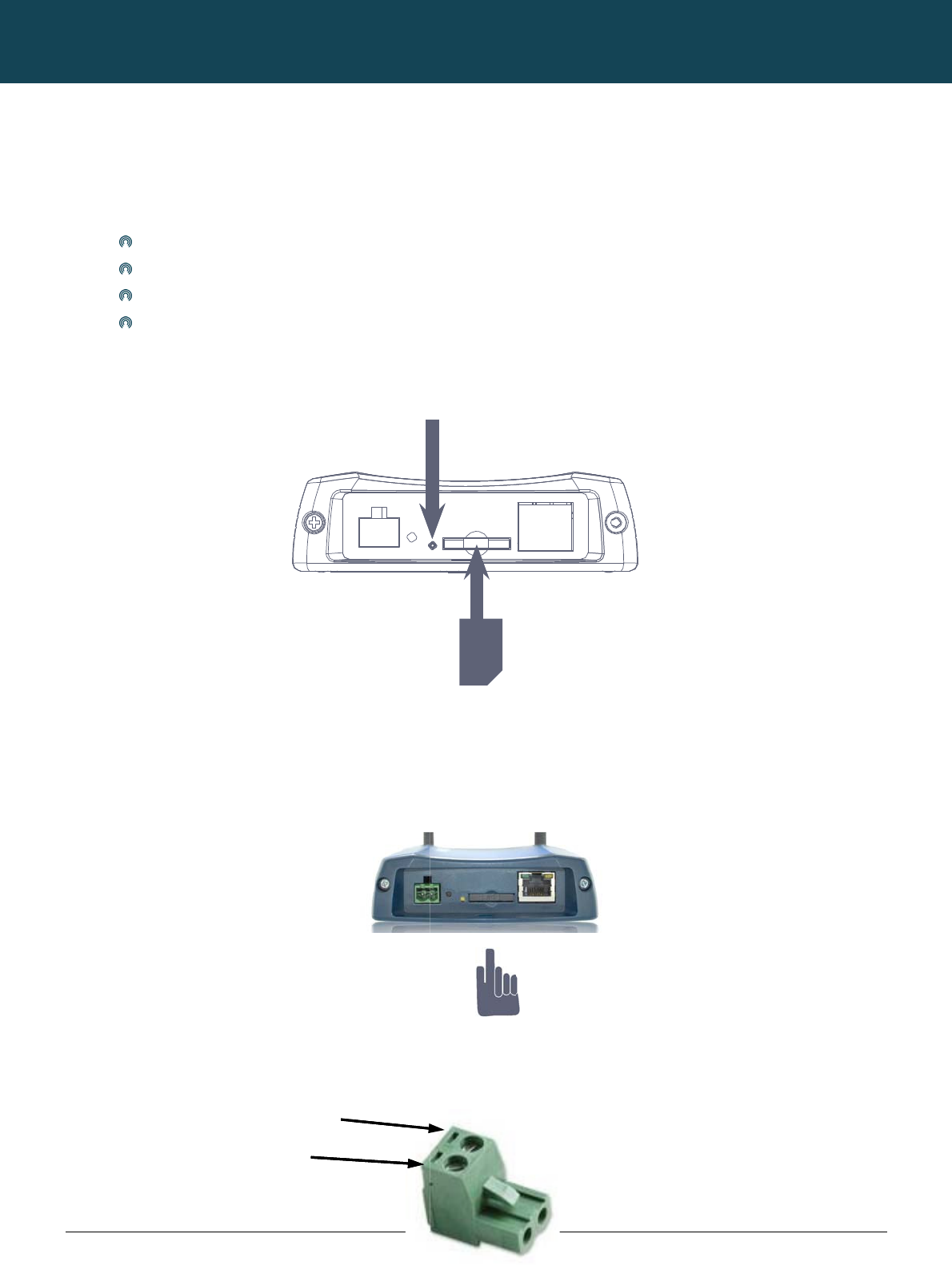
rting the SIM
C
s
s the SIM ‘Eject’ but
t
w
n below:
e
tting Up t
h
c
h the supplied ante
on the panel should
a
rity of DC Pow
s
trial M2M Wireless
R
c
om
g
urin
g
n
g hardware compo
n
r supply (8-28VDC)
n
et cable
o
p or PC
e
SIM card
C
ard
t
on to eject SIM card
h
e Cellula
r
nna to the router by
s
illuminate
w
er Plug Screw
T
Negat i
P
o
R
outers
g
you
r
n
ents to set up the ro
bay. Make sure the
r
Router
s
crewing it onto the
a
.
T
erminal
ve -
o
sit ive+
r
Rou
t
u
ter:
SIM card is inserted
a
ntenna connector.
C
NETCOMM
t
e
r
correctly by insertin
g
Pr
ess
the
S
C
onnect the power a
d
+
V
CALLDIRECT™
g
the SIM with the g
o
S
IM Eject
button
d
apter to the mains
a
Insert your
M
SERIES – NT
C
ld side facing down
a
nd plug the output i
n
M
obile Broadband SIM Car
d
C
-6000 Serie
on the SIM card ba
y
n
to the power jack o
f
r
d
YML6908
s
and in the direction
f
the router. The red
p
as
p
ower

YML6908 NTC-6000 Series User Guide
www.netcommwireless.com
11
NTC-6000 Series – Industrial M2M Wireless Routers YML6908
12
www.netcommwireless.com
NETCOMM CALLDIRECT™ SERIES – NTC-6000 Series
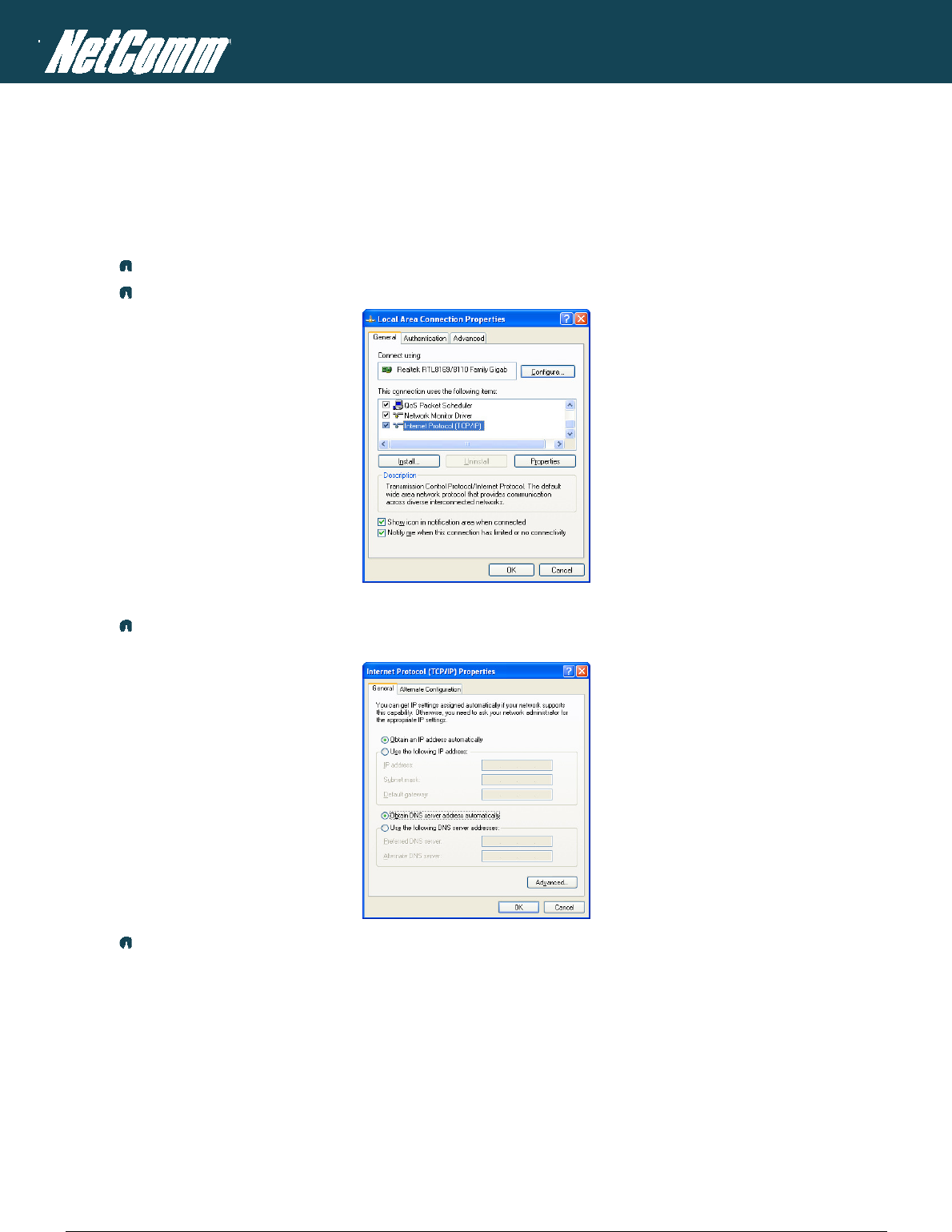
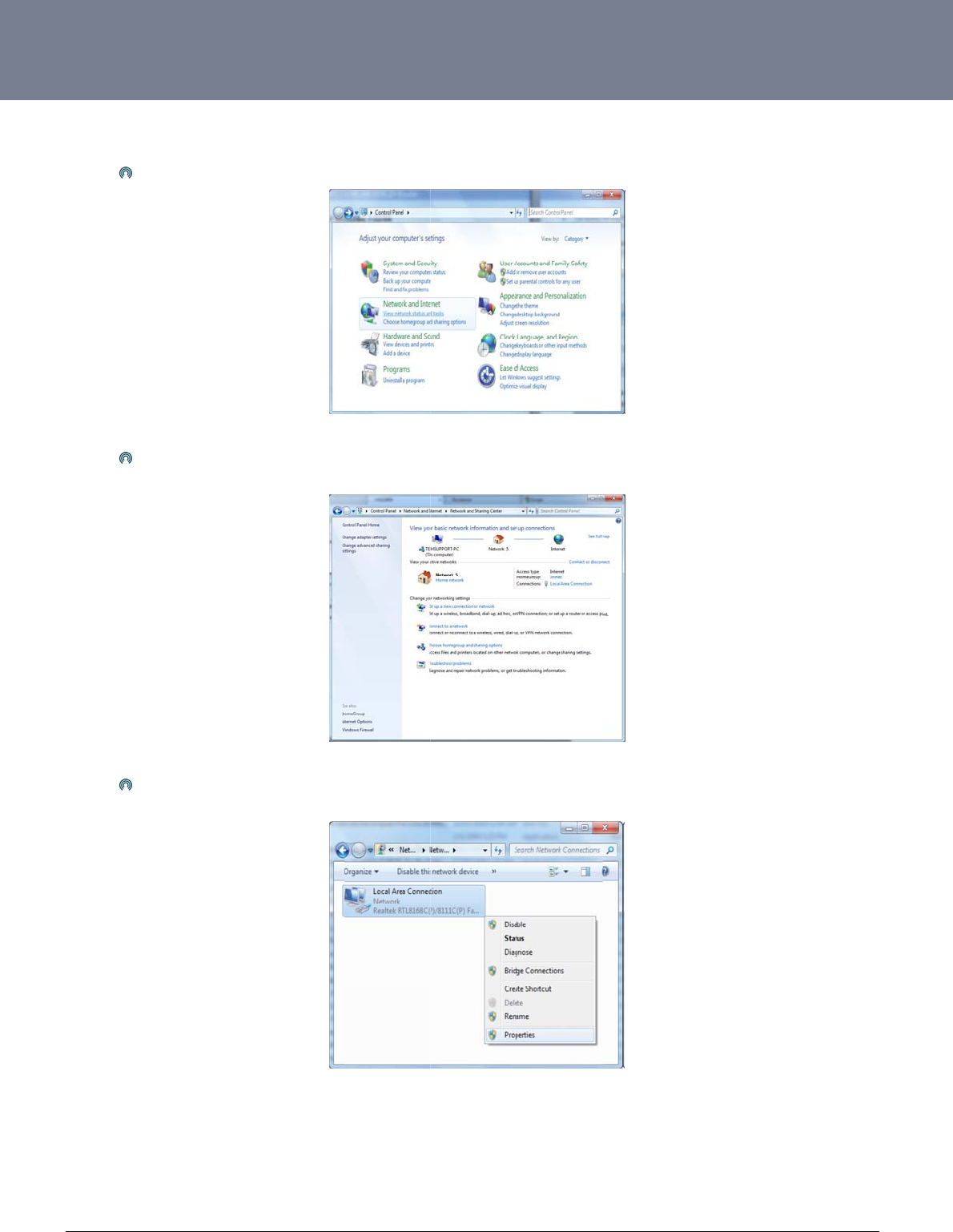
Preparing Your Computer
Connect one end of the supplied Ethernet cable to the Ethernet port of your router. Connect the other end of the cable to the LAN port of your computer. Configure your PC’s Ethernet interface to
use a dynamically assigned IP address by completing one the following steps that correspond to the operating system your computer has installed.
Ethernet interface configuration in Windows XP
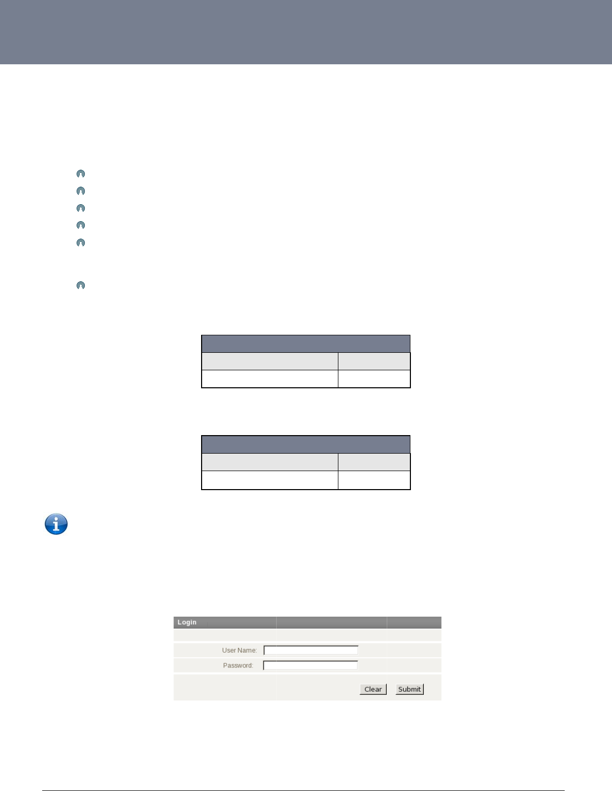
Click on the Start button, select “Control Panel” and then “Network Connections”.
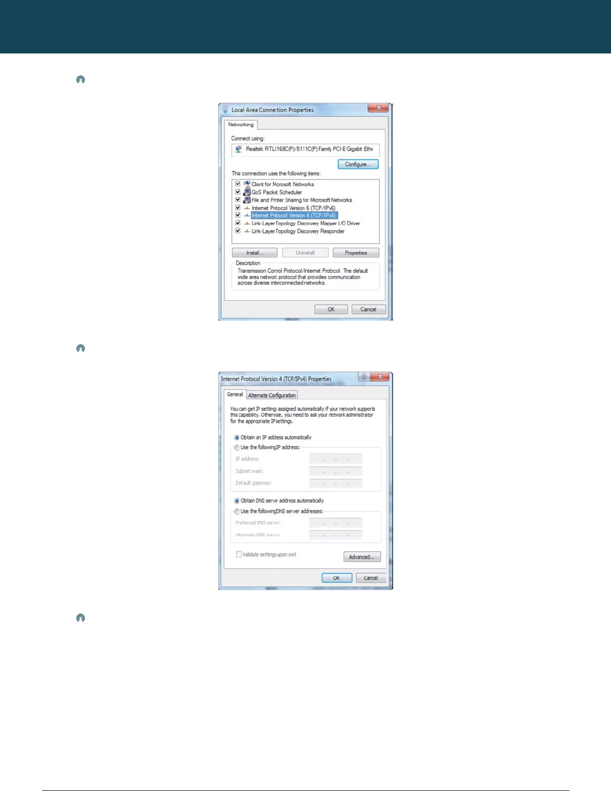
Right click on “Local Area Connection” and select the Properties option to open the configuration dialogue box as shown below:
Figure4:LocalAreaConnectionProperties
Find and select Internet Protocol (TCP/IP) from the protocol list box and then click the Properties option. The TCP/IP configuration window will pop up as illustrated below.
Under the General tab, select the radio button ‘Obtain an IP address automatically’ and ‘Obtain DNS server address automatically’.
Figure5:InternetProtocol(TCP/IP)Properties
Press the OK button to close the TCP/IP configuration window. Then press the Close button to complete the computer preparation for the router.
YM
L
ww
w
13
Eth
L
6908
w
.netcommwireless.c
ernet Interface
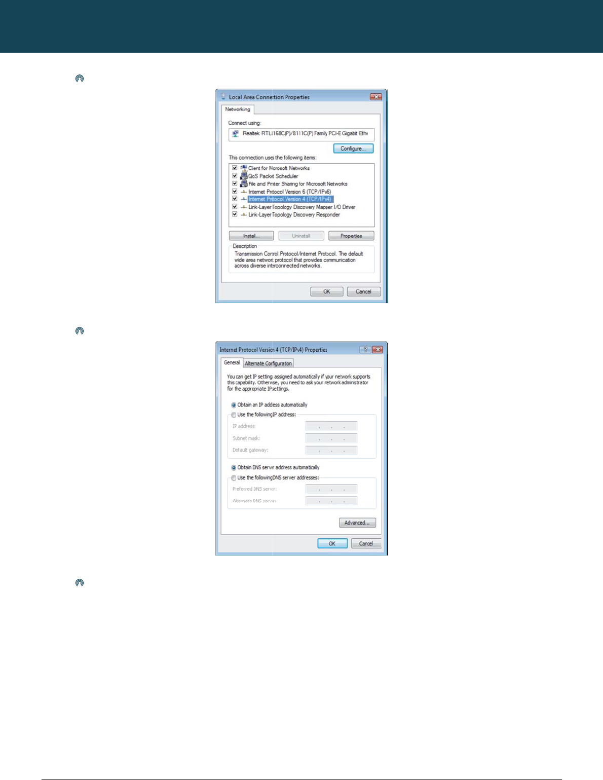
Click
In the
Singl
e
c
om
Configuration i
n
on the Start button.
T
Manage network co
e
RIGHT click on “Lo
n
Windows Vist
a
T
hen select “Control
P
nnections, click on “
M
cal Area connection
”
a
P
anel” followed by “
N
M
anage network co
n
Figure7:
W
”
, then click “Properti
Figure
N
etwork and Sharing
F
n
nections” to continu
e
W
indowsVista‐Ne
t
i
es”.
8:RightClickingL
o
Centre”.
F
igure6:Windows
V
e
.
t
workandSharing
C
o
calAreaConnectio
V
istaControlPane
l
C
ente
r
n
andSelectingPro
NTC-6000 Series
U
o
perties
U
ser Guide
NT
C
14
ww
w
C
-6000 Series – Indu
s
w
.netcommwireless.c
The
Selec
Click
s
trial M2M Wireless
R
c
om
screen will display t
h
t “Obtain an IP addr
e
on the “OK” button
a
R
outers
h
e information “User
e
ss automatically” a
n
a
nd close the Local
A
Account Control” an
Figure9:D
o
n
d “Obtain DNS serv
e
A
rea Connection Pro
p
NETCOMM
n
d click “Continue” t
o
o
ubleClickInternet
e
r address automati
c
Figure10:S
p
erties window to co
m
CALLDIRECT™
o
continue and then
d
ProtocolVersion4
c
ally” before clicking
e
tPropertiestoAu
t
m
plete the computer
SERIES – NT
C
d
ouble click on “Inter
n
(TCP/IPv4)
on the “OK” button t
o
t
omaticSettings
preparation for the r
o
C
-6000 Serie
r
net Protocol Version
t
o continue.
r
outer.
YML6908
s
4 (TCP/IPv4)”.
YM
L
ww
w
15
Eth
L
6908
w
.netcommwireless.c
ernet Interface
Click
In the
Singl
e
c
om
Configuration i
n
on the Start button,
s
“Network Settings”
w
e
RIGHT click on “Lo
n
Windows 7
s
elect the “Control P
a
w
indow select the “
C
cal Area Connection
a
nel (in Category Vie
w
hange Adapter Setti
n
”
, then click “Propert
Figure13:Win
d
w
)” option and then
c
Figure1
1
ngs” option to contin
Figure12:Windo
w
t
ies”.
d
ows7‐Selecting
L
c
lick on the “View N
e
1
:Windows7Contr
o
ue.
w
s7NetworkandS
L
ocalAreaConnect
i
twork Status and Ta
s
o
lPane
l
h
aringCente
r
onProperties
NTC-6000 Series
U
s
ks”.
U
ser Guide
NT
C
16
ww
w
C
-6000 Series – Indu
s
w
.netcommwireless.c
Doub
Click
Clic
s
trial M2M Wireless
R
c
om
le click on “Internet
P
on “Obtain an IP ad
d
k on “OK” to comple
R
outers
P
rotocol Version 4 (T
C
d
ress automatically”
a
te the computer pre
p
C
P/IPv4)”.
Figure14:D
o
a
nd “Obtain DNS se
r
p
aration for the route
r
NETCOMM
o
ubleClickInterne
t
r
ver address automa
Figure15:SetPro
p
r.
CALLDIRECT™
t
ProtocolVersion4
tically” then click on
p
ertiestoAutomat
i
SERIES – NT
C
(TCP/IPv4)
“OK” to continue.
i
cSettings
C
-6000 Serie
YML6908
s
YM
L
ww
w
17
A
c
The
r
The
The
syst
e
To l
o
To l
o
The
1.
2.
L
6908
w
.netcommwireless.c
c
cessing t
h
r
e are two system m
a
root manager accou
admin manager (ad
m
e
m options not avail
a
Firm
w
De
v
Uplo
a
Res
Syste
is bei
n
Once
TR-
0
o
gin to the router in r
o
o
gin to the router in
a
NOTE – Whene
v
steps required to ac
c
Open your web b
r
Click Login and t
y
c
om
h
e Router
W
a
nagement accounts
nt is has full permiss
m
inistrator) account
h
a
ble to an admin use
w
are Upgrade – The
a
v
ice Configuration Ba
a
d - Uploading previ
o
tore Factory Default
s
m Configuration setti
n
g transmitted. It do
e
the internet connec
t
0
69 settings - Remot
e
o
ot manager mode,
p
a
dmin manager mod
e
v
er you make chang
e
c
ess the route
r
’s we
b
r
owser (e.g. Internet
y
pe “admin” (without
W
eb User
for maintaining the
s
ion privileges and c
a
h
as access to the m
a
r are:
a
bility to install an u
p
ckup – the option of
o
usly saved settings
s
- Setting the router
t
ngs – The TCP Kee
p
e
s this by periodicall
y
t
ion is deemed to be
e
management func
t
p
lease use the follo
w
e
, please use the foll
o
e
s, please refresh y
o
b
browser configurat
Explorer/Firefox/Saf
a
quotes) in the Usern
Interface
s
ystem, root and ad
m
a
n use every comma
n
a
jority of route
r
settin
g
graded version of th
e
saving the router’s c
t
o the route
r
.
t
o factory default set
t
p
alive function can b
e
y
sending a ping (IC
M
down the router will
a
t
ion allowing the aut
o
w
ing login details:
User Na
m
Passwo
r
o
wing default login d
User Na
m
Passwo
r
o
ur web page (press
i
on is illustrated belo
w
a
ri) and navigate to h
t
ame and Password
f
NT
C
‐6
0
m
in, which both have
nd option that the ro
u
gs available except
t
e router’s software.
urrent settings, usef
u
t
ings, essential after
e
used to ensure the
MP) request messa
g
a
ttempt to reconnec
t
o
-configuration of en
d
http://192.168.20.
1
m
e
r
d
Tabl
e
d
etails.
http://192.168.20.
1
m
e
r
d
Table5
:
the F5 key) to preve
n
w:
ttp://192.168.20.1/.
f
ields. Then click on
t
0
00SeriesLoginat
slightly different rou
t
u
ter is configured wi
t
t
he router’s system o
u
l for configuring mul
a firmware upgrade.
current live mobile
b
e to a WAN IP addr
e
t
to the WWAN mobil
e
d
-user device.
1
root
admin
e
4:RootAccessDe
t
1
admin
admin
:
AdminAccessDet
a
n
t errors occurring d
u
t
he Submit button.
http://192.168.20.
t
e
r
management cap
h.
p
tions that can alter
o
tiple NTC-6000 rout
e
b
roadband connectio
ss or a well-known i
n
e
broadband provid
e
t
ails
a
ils
u
e to caching.
1
NTC-6000 Series
U
p
abilities.
or copy the router’s
f
e
rs.
o
n is still alive even
w
n
ternet domain host
s
e
r.
U
ser Guide
f
irmware (software).
T
w
hen no data packet
t
s
uch as www.google
T
he
t
raffic
.com.
NT
C
18
ww
w
U
n
If th
e
the
r
If th
e
C
-6000 Series – Indu
s
w
.netcommwireless.c
n
locking t
h
e
SIM card is locked
r
outer Status page:
e
SIM Status shows t
h
Click
When
Click
Enter
Click
s
trial M2M Wireless
R
c
om
h
e SIM Ca
r
it can only be unloc
k
he SIM is locked as
s
on the “Internet Setti
you click on the ‘SI
M
OK
the PIN code in the
P
on the Status link an
d
R
outers
r
d
k
ed using a PIN that
w
s
hown above, you s
h
ngs” menu and sele
c
M
Security’ menu ite
m
P
IN and Confirm PIN
d
the Home Status p
Figure
1
w
as assigned to you
h
ould be automaticall
c
t “Mobile Broadban
d
m
you should see the
fields. Then click th
e
a
ge should look as
b
Fig
u
NETCOMM
1
9:SIMStatusLoc
k
r SIM card by your
m
ly redirected to the
S
d
” followed by “SIM
S
following message:
-
Figure21
e
Save button.
b
elow with SIM Statu
s
u
re23:StatusPage
CALLDIRECT™
k
ed
m
obile broadband pr
o
S
IM unlock page. If n
o
S
ecurity”.
-
:PINCodeUnlock
M
Figure22:PINS
e
s
‘SIM OK’:
‐SIMCardUnlocke
SERIES – NT
C
o
vide
r
. To check if th
o
t, then select the fol
M
essage
e
ttings
d
C
-6000 Serie
h
e SIM card is locke
d
lowing:
YML6908
s
d
view the SIM Status
on

YML6908 NTC-6000 Series User Guide
www.netcommwireless.com
19
NTC-6000 Series – Industrial M2M Wireless Routers YML6908
20
www.netcommwireless.com
NETCOMM CALLDIRECT™ SERIES – NTC-6000 Series
Enter PUK Code
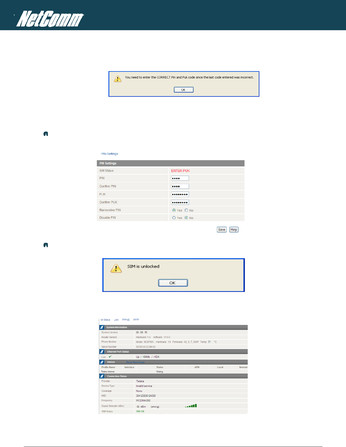
If after three incorrect attempts at entering the PIN code, you will be requested to enter a PUK code.
Figure24:EnterCorrectPINandPUKMessage
The PUK code is sometimes referred to as a PIN Unlocked Key (PUK) code. You will need to contact your mobile broadband provider to obtain this number.
Your mobile broadband provider will issue you a PUK code which will enable you to unlock the SIM card and enter a new PIN code.
Enter the new PIN and PUK codes as shown below and click Save.
If you have entered the PUK correctly you should see the following message:
Figure27:PUKCodeCorrectlyEnteredResponse
Now click on the “Status” menu item at the top left-hand side of the page. It should reflect the screenshot below and show a SIM Status of ‘SIM OK’:
Figure28:Status‐PINUnlocked

YML6908 NTC-6000 Series User Guide
www.netcommwireless.com
21
The ‘Remember PIN’ Feature
This feature allows the router to automatically send the PIN to the SIM each time the SIM asks for it (usually at power up).
This enables the SIM to be PIN Locked (to prevent unauthorized use of the SIM card elsewhere), while still allowing the router to connect to the cellular service.
When this feature is enabled the PIN entered by the user when they set the “Remember PIN” feature is encrypted and stored locally in the router. The next time the SIM asks the router for the PIN
the router decrypts the PIN and automatically sends it to the SIM without user intervention.
When this feature is disabled and the SIM is PIN locked, the user must manually enter the PIN via the router‘s configuration interface. This is clearly not desirable where the router is unattended.
NT
C
22
ww
w
C
e
Lo
c
You
You
that
C
-6000 Series – Indu
s
w
.netcommwireless.c
e
llular Ban
d
c
king To a Spe
c
may want to lock th
e
may want to do this
i
suit your requireme
n
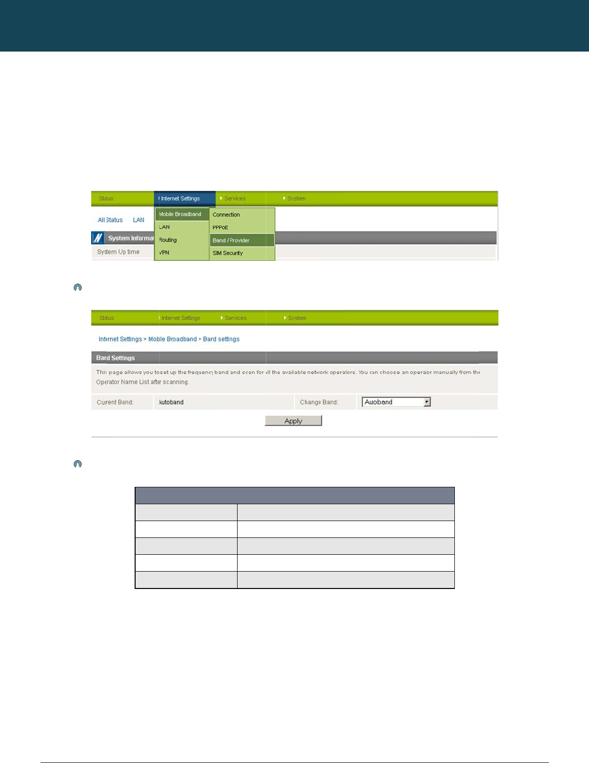
Make
The f
o
s
trial M2M Wireless
R
c
om
d
and MB
B
c
ific Band
e
router to a specific
if you’re using the ro
u
n
ts.
your selection from
t
o
llowing band settin
g
UMTS 85
0
UMTS 85
0
2G
WCDMA
A
ALL BAN
D
R
outers
B
Provider
band. To do this, cli
c
u
ter in a country with
t
he “Change Band:”
g
s options are applic
a
0
Mhz, 2G
0
MHZ ONL
Y
A
ll
D
S (AUTOBAND)
Selection
c
k on the “Internet S
e
multi frequency net
w
Figure29:Band
/
drop down list.
a
ble.
BAND SEL
E
UMTS 85
0
UMTS 850
M
GSM/EDG
E
UMTS 85
0
UMTS 85
0
NETCOMM
e
ttings” menu and se
w
orks that may not a
/
ProviderMenuOp
t
Figure30:BandS
e
ECTION OPTIONS
0
MHz GSM/EDGE/GPRS
9
MHz Only
E
/GPRS 900/1800/1900MH
z
0
/2100/1900MHz
0
/2100/1900MHz GSM/ED
G
Table
6
CALLDIRECT™
lect “Mobile Broadb
a
l
l suppo
r
t HSPA. Yo
u
t
ion
e
ttings
– NTC-6908
9
00/1800/1900MHz
z
G
E/GPRS
6
:NTC‐6908BandS
SERIES – NT
C
a
nd” followed by the
can select the route
e
lectionOptions
C
-6000 Serie
“Band / Provider” m
e
e
r to only connect on
YML6908
s
e
nu item on the right
.
the network frequen
c
.
c
ies
YM
L
ww
w
23
C
h
The
To s
1.
2.
3.
4.
The
L
6908
w
.netcommwireless.c
Click
NOTE:
A
h
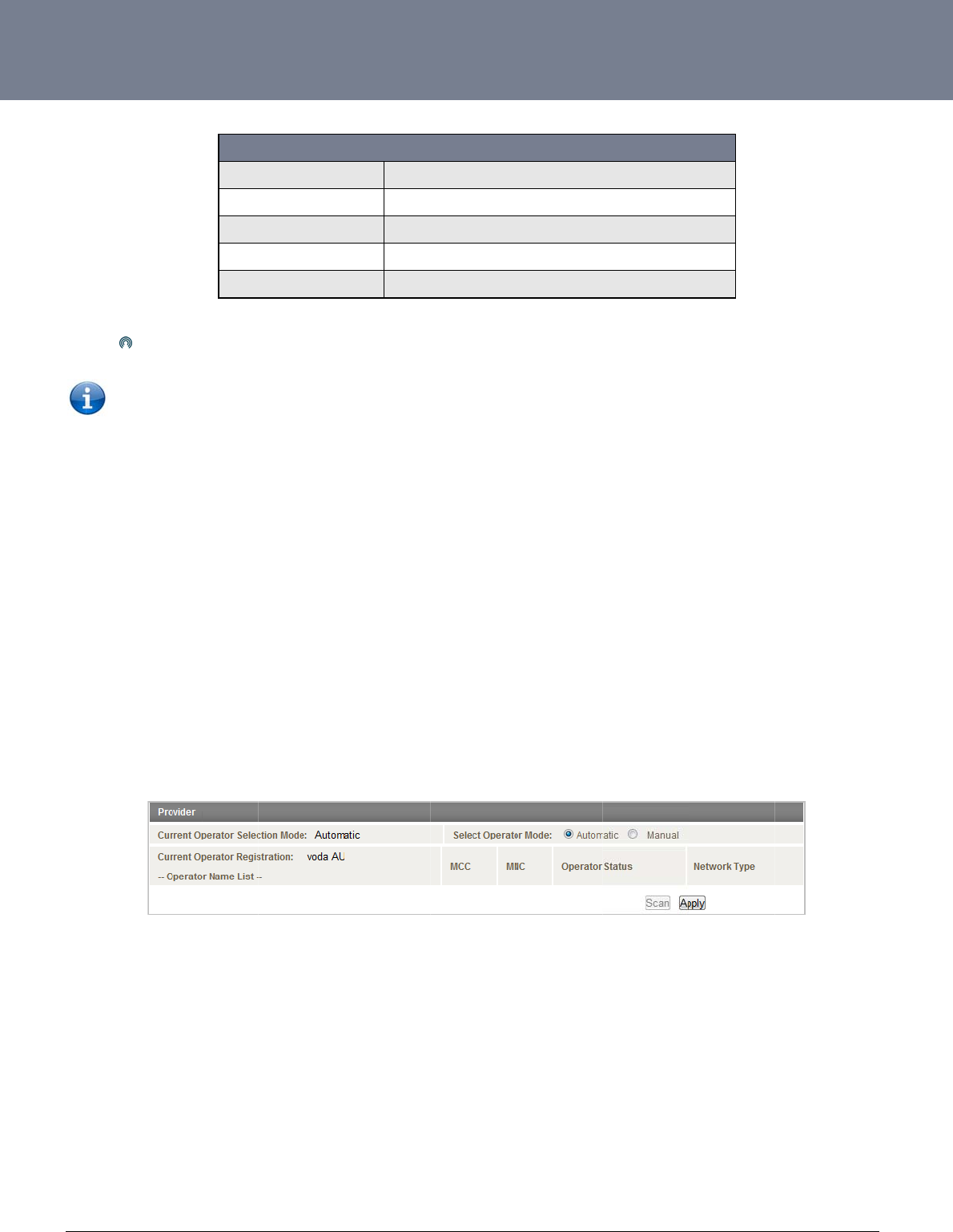
oosing Y
o
default setting is “A
u
can manually for av
a
If you are currentl
y
by clicking on the
Set the operator
m
Click on the Scan
Select your chose
router will then use t
h
c
om
UMTS 90
0
WCDMA
A
UMTS 90
0
2G
ALL BAN
D
Save to confirm the
n
A
fter changing the ba
o
ur Mobile
u
tomatic”.
a
ilable cellular netwo
r
y
connected to the i
n
“Internet Settings”
m
m
ode to Manual
button. A list of cell
u
e
n provider from the l
h
e chosen operator
t
0
Mhz Only
A
ll
0
MHz, 2G
D
S (AUTOBAND)
n
ew band settings
.
nd, if the change is
n
Broadban
r
k operators (provid
e
n
ternet, disconnect y
o
m
enu and selecting “
m
u
lar operators in the
v
ist of detected oper
a
t
o attempt to connec
t
BAND SEL
E
UMTS 90
0
UMTS 900/
2
UMTS 900
M
GSM/EDG
E
UMTS 85
0
Table7:NTC‐69
0
n
ot reflected on the f
r
d Provide
r
e
rs) follow the steps
b
o
ur session and ens
u
m
obile broadband“ f
o
v
icinity of your router
a
tors and click the A
p
t
to the cellular servi
c
Figure31:Selec
t
ECTION OPTIONS
0
MHz Only
2
100/1900MHz
MHz GSM/EDGE/GPRS 8
5
E
/GPRS 850/900/1800/190
0
0
/900/2100/1900MHz GS
M
0
9BandSelection
O
r
equency field on th
e
r
Manually
b
elow:
u
re “Auto Connect” i
s
ollowed by the “Con
n
should appear und
e
p
ply button
c
e profile you have e
t
ingaBandManua
l
– NTC-6909
5
0/900/1800/1900MHz
0
MHz
M
/EDGE/GPRS
O
ptions
e
“Status” page then
s
disabled in the cur
r
n
ection” menu item).
e
r the “Operator Nam
lected to use.
l
l
y
y
ou may need to re
b
r
ent cellular connecti
o
e
List” heading.
NTC-6000 Series
U
b
oot the router.
on profile you are u
s
U
ser Guide
ing (You can check
t
t
his
NTC-6000 Series – Industrial M2M Wireless Routers YML6908
24
www.netcommwireless.com
NETCOMM CALLDIRECT™ SERIES – NTC-6000 Series
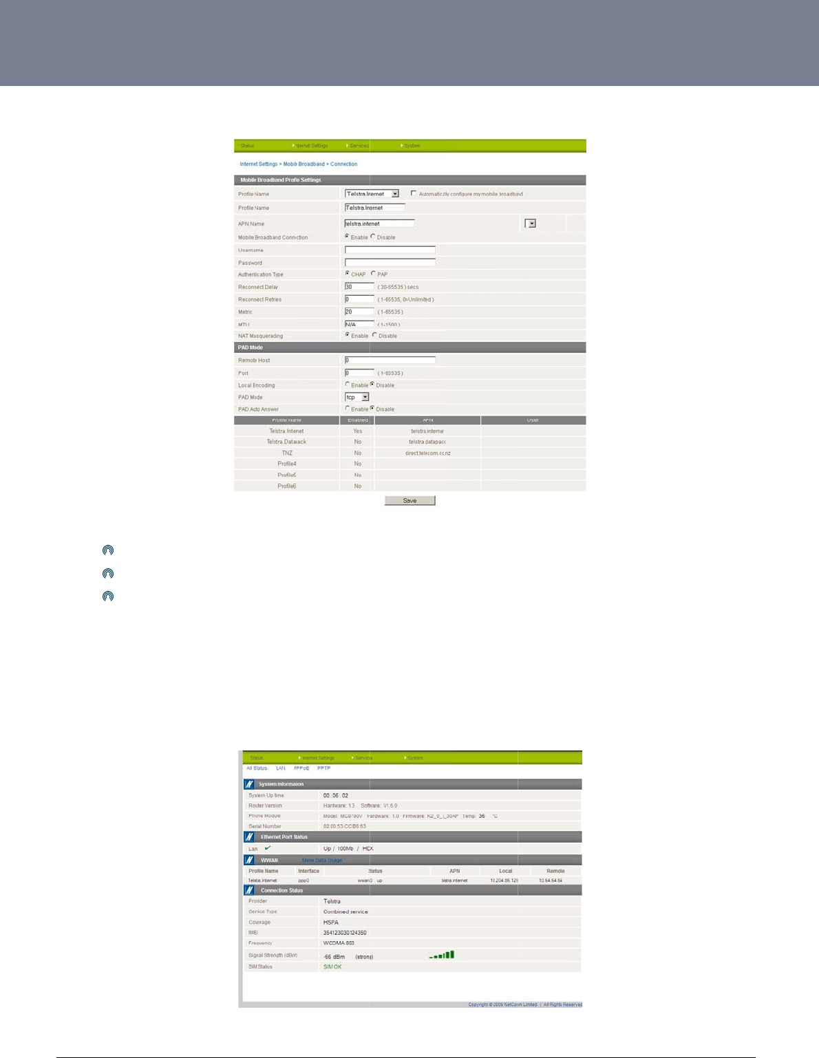
Establishing a Connection to a Cellular Network
This section describes how to configure the router to initiate a Mobile Broadband connection. There are 2 possible methods that can be used to set up a Mobile Broadband connection via PPP:
Initiating the PPP Connection directly from the router (most common).
Initiating the PPP Connection from a different PPP client (i.e. laptop or router) with the router running in transparent PPPoE mode.
Initiating a PPP Connection Directly from the Router
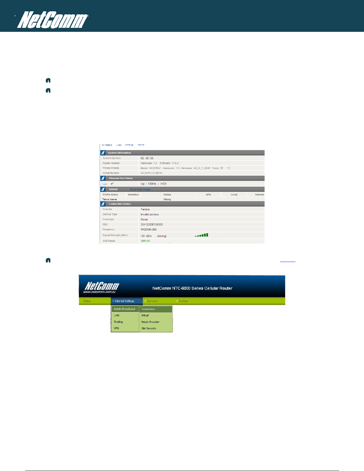
The status page of the router should be displayed as below. Please ensure that the SIM Status is ‘SIM OK’ before you initiate a Mobile Broadband connection.
Figure32:StatusPage‐SimOk
Click on click on the “Internet Settings” menu and select “Mobile Broadband” followed by the “Connection” option on the right as shown in Figure 33 below.
Figure33:MobileBroadband‐ConnectionOption
YM
L
ww
w
25
Co
n
The
Fro
m
T
o
Sel
e
net
w
Con
g
L
6908
w
.netcommwireless.c
n
necting to the
router supports mult
i
First
e
Selec
Selec
m
now on, Auto Conn
o
Confirm
a
ct the Status link to r
w
ork has allocated to
g
ratulations, the rout
c
om
Internet using
a
iple APN profiles; th
a
e
xamine the list of co
t the profile that you
t “Enable” for the Au
t
ect will remain enab
l
a
Succes
s
r
eturn to the status p
a
the router.
er is now ready to u
s
a
Connection Pr
o
a
t allow you the route
nfigured profiles
wish to connect with
t
o Connect option a
n
l
ed and the router wi
s
ful
Conne
a
ge. Pay close atten
t
s
e!
o
file
r settings to be confi
Figure34:Mobil
and make sure that
n
d click Save.
l
l automatically conn
e
ction
t
ion to WWAN sectio
n
Figure35:Statu
s
gured to connect to
l
eBroadband‐Con
n
the APN name field i
ect unless you retur
n
n
on the page. The
W
s
Page‐WWANSt
a
different cellular net
w
n
ectionPage
s correct. This is ver
y
n
to this page and di
s
W
WAN status should
a
tusUp
w
orks
y
important
s
able it.
b
e ’’up”. The Local fi
e
NTC-6000 Series
U
eld will show the cu
r
U
ser Guide
rent IP address that
t
t
he
NT
C
26
ww
w
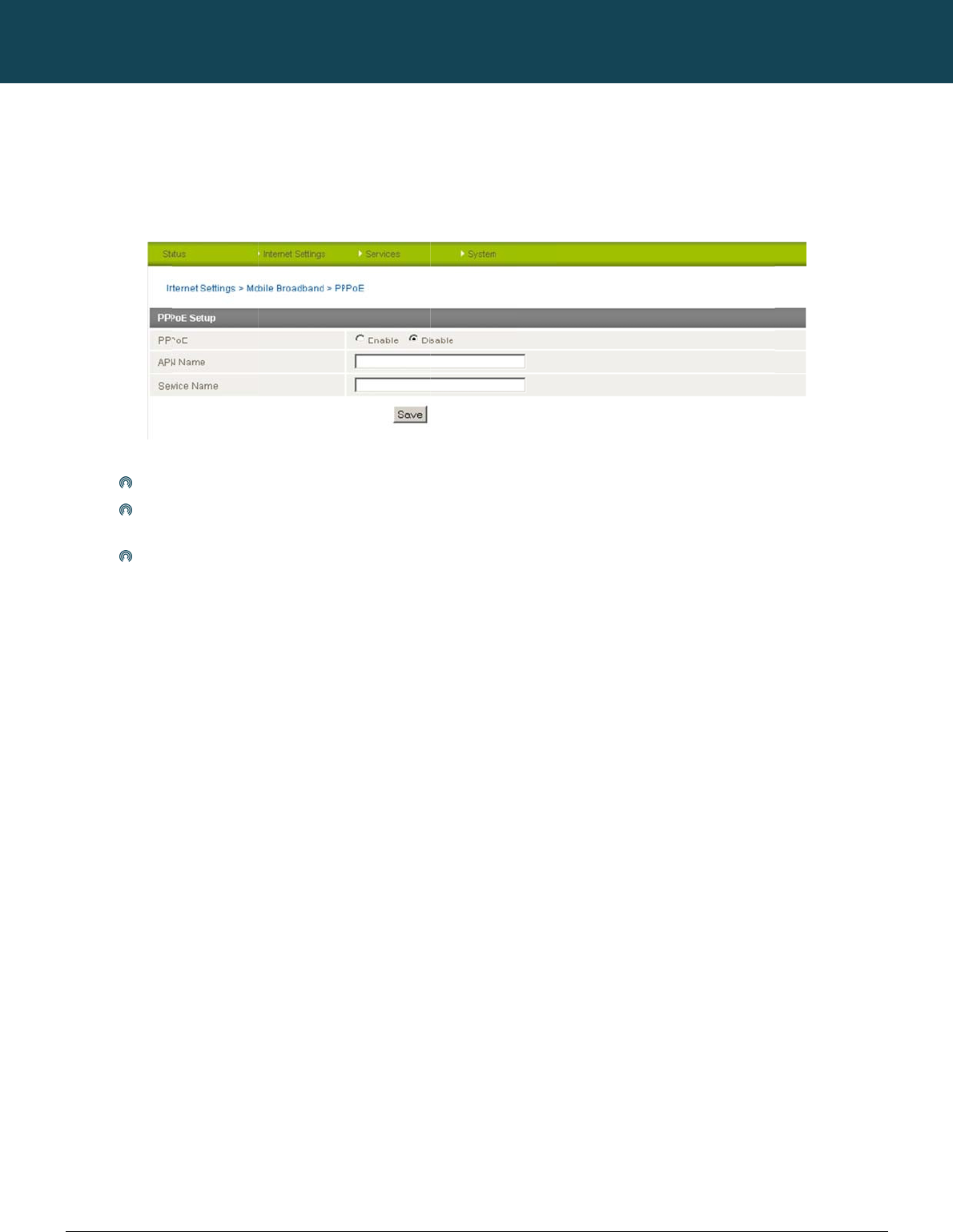
Init
i
To
e
sele
c
The
n
C
-6000 Series – Indu
s
w
.netcommwireless.c
i
ating a Conne
c
nable PPPoE mode,
c
t “Mobile Broadban
n
select the PPPoE p
Selec
Speci
use t
h
Finall
y
s
trial M2M Wireless
R
c
om
c
tion using the
R
ensure the “Auto Co
d” followed by the “
C
age by clicking on t
h
t “Enable” to enable
fy the APN you wish
h
e same service na
m
y
click “Save” to sav
e
R
outers
R
outer in Trans
p
nnect” option is disa
C
onnection” menu it
e
h
e “Internet Settings”
PPPoE mode.
to use to suit your c
a
m
e when connecting.
e
your settings and
e
p
arent PPPoE m
o
bled in each of the
p
e
m. Select each con
n
menu, then select “
M
Figure36:Mobil
a
rrie
r
. In addition you
This facility is partic
u
nable PPPoE.
NETCOMM
ode
p
rofiles on the “Conn
e
n
ection profile and di
M
obile Broadband” f
l
eBroadband‐PPP
o
u
may specify an opti
u
larly useful if you ha
CALLDIRECT™
e
ction” configuration
sable the Auto Conn
o
llowed by the “PPP
o
oE
onal “Service Name
”
ve more than one P
P
SERIES – NT
C
page. To check this
e
ction option and sa
v
o
E” option.
. When a “Service N
a
P
PoE router or mode
m
C
-6000 Serie
click on the “Interne
a
ve the updated setti
n
ame” is specified th
e
m
on a single Ethern
e
YML6908
s
t Settings” menu, th
e
n
gs.
e
connected device
m
e
t network.
e
n
m
ust
YML6908 NTC-6000 Series User Guide
www.netcommwireless.com
27
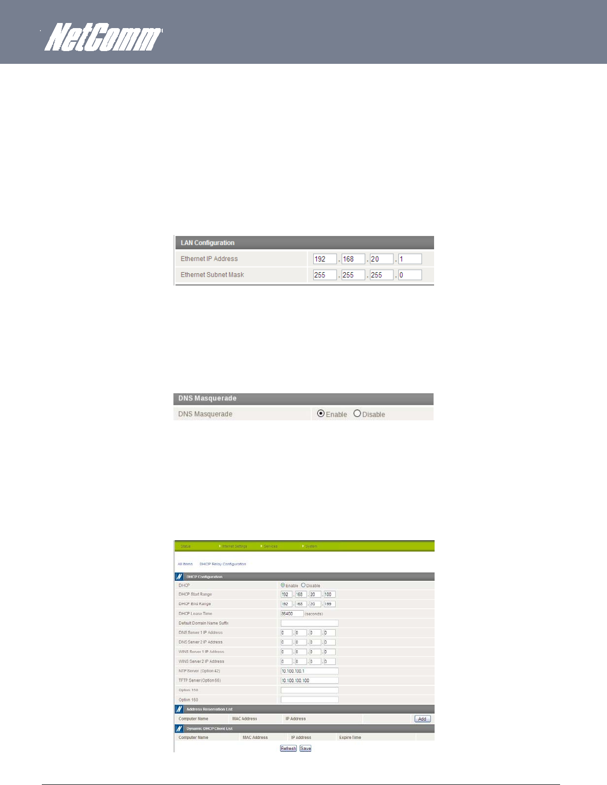
Ethernet Related Commands
How to configure the Ethernet IP address
The IP settings can be configured by clicking on the “Internet Settings” menu followed by “LAN” and then “IP Setup”
The default IP of the Ethernet port is 192.168.20.1 with the subnet mask 255.255.255.0.
If you wish to change this then simply enter the new IP address and click on the Save button at the bottom of the page.
Since the IP address has changed you will have to re-enter the new IP address configured in your browser to access the configuration pages.
Figure37:LAN‐IPSettings
How to Configure DNS Masquerading
DNS masquerading allows the router to forward DNS requests to dynamically assigned DNS servers. Clients on the router’s LAN can then use the router as a DNS server without needing to
know of the dynamically assigned DNS servers assigned by the cellular network.
There should be no need to disable this feature in most cases, however, if you need to do so simply select “Disable” and click the Save button.
Figure38:DNSMasqueradingSetting
How
to
Configur
e
the DHCP
Server
Use the following procedure to change the router’s DHCP server default settings. Ensure your PC’s Ethernet connector is configured to automatically obtain an IP and DNS server address.
When you plug in the Ethernet cable to your PC, the router should automatically assign it an IP address within 10-15 seconds. Please be aware that you will be sharing the bandwidth of the
router between all connected devices. You can manually set DNS1 and DNS2 or if DNS Masquerade is enabled the DHCP DNS1 address will automatically be set to the router’s LAN address.
Figure39:DHCP
This example has a start address of 100, an end address of 199, lease time of 86,400 seconds, and uses the DNS servers that are auto-assigned by the network upon connection.
NTC-6000 Series – Industrial M2M Wireless Routers YML6908
28
www.netcommwireless.com
NETCOMM CALLDIRECT™ SERIES – NTC-6000 Series
If you do not enter the DNS1 and DNS2 addresses manually, then to browse the Internet from your Ethernet connected device you must enable DNS Masquerade (see above).
Upon enabling DNS Masquerade, you will notice that the DNS1 address is automatically set to the IP address of the Ethernet port. DNS addresses are then automatically assigned by the
connection to the network.
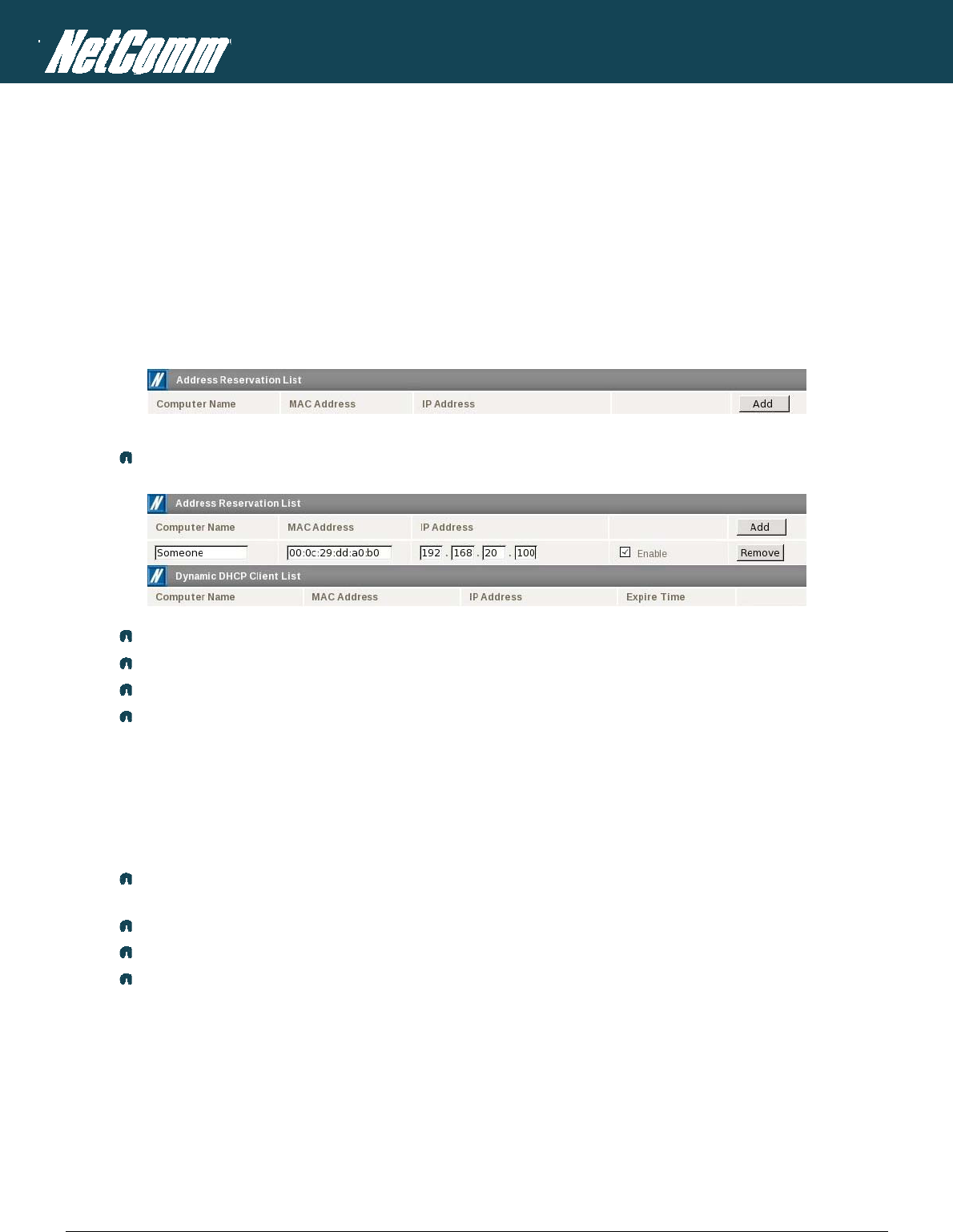
How to Configure Static DHCP Assignments
This facility is available by clicking on the “Internet Settings” menu followed by “LAN” and then the “DHCP” menu item on the right.
You may assign a particular IP address to a specific device every time that device makes a DHCP request as follows:
Figure40:StaticIPAssignment
Click the Add button.
Enter a name for the computer or device.
Enter the computer or device’s MAC address.
Enter the IP address to assign.
Click Save.
How to configure your device’s IP address manually (no DHCP)
If your device has a static IP address set, you can configure your device to work with the router by manually configuring your device to the following settings:
Set your device’s IP address to any valid IP address between 192.168.20.2 and 192.168.20.99 or disable the DHCP server and use any address. Do not use the IP address
assigned to the router’s Ethernet interface.
Set your device’s subnet to: 255.255.255.0.
Set your Gateway to the IP address of the router’s Ethernet interface: 192.168.20.1
Set DNS (if required) to 192.168.20.1 or configure manually to your mobile broadband provider’s DNS Servers.
YM
L
ww
w
29
Vi
r
A Vi
r
gen
e
PPT
P
rout
e
The
C
o
This
L
6908
w
.netcommwireless.c
r
tual Priva
t
r
tual Private Network
e
rally not visible to p
u
P
and GRE are com
m
e
rs.
advantages of the V
P
Data
P
Acce
s
Data
O
Data
I
o
nfiguring
facility is available
b
c
om
t
e Network
(VPN) is a tunnel pr
o
u
blic network.
m
on encapsulation
m
P
N feature include:
P
rotection.
s
s Control.
O
rigin Authenticatio
n
Integrity.
a PPTP /
G
b
y clicking on the “In
t
s
o
viding a private link
m
ethods used to crea
n
.
G
RE conne
t
ernet Settings” men
u
between two netwo
r
t
e a virtual private n
e
ction
u
followed by the “V
P
Fi
g
Fi
g
r
ks or devices over a
e
twork (VPN) over p
u
P
N” menu item.
g
ure41:InternetSe
t
g
ure42:InternetSe
t
public network. Dat
a
blic networks. Open
V
t
tings‐VPN‐PPTP
t
tings‐VPN–GRE
a
to be sent via a VP
N
V
PN and IPSec can
a
NTC-6000 Series
U
N
needs to be enca
p
a
lso be configured o
U
ser Guide
p
sulated and as suc
h
n the NTC-6000 seri
e
h
is
e
s

NT
C
30
ww
w
The
r
Ste
Ste
Exa
m
If th
e
Rou
t
Edi
If yo
Dis
If yo
and
Ho
w
PPT
P
C
-6000 Series – Indu
s
w
.netcommwireless.c
r
e are a few configur
a
p 1: Connect t
o
Click
click ‘
To ch
For m
p 2: Enabling P
Click
Press
Set th
Enter
Press
To ch
NOTE – It
m
Gateway IP
m
ple:
e
PPTP/GRE server
a
t
ing > Static), you w
o
10.0.
0
255.0
203.4
1 in t
h
ting the PPTP/
G
u need to edit the P
P
abling PPTP/G
R
u want to completel
y
then disabling the P
P
w
ever, if you want to l
e
P
/GRE interface will
a
Note: GRE TTL
s
trial M2M Wireless
R
c
om
a
tion steps you will n
o
the Cellular Br
o
on the “Internet Setti
‘
enable’ for the appr
o
eck that the PPP int
e
ore details on enabli
PTP:
on the VPN menu ite
the Add button and
e “Enable VPN” opti
o
the PPTP/GRE serv
e
the “Save” button.
eck that the PPTP/G
R
m
ay be necessary to
address box.
a
ddress is 203.44.25
1
o
uld need to enter th
e
0
.0 in the Destination
.0.0 in the IP subnet
4.251.100 in the Gat
e
h
e metric box.
G
RE credentials
P
TP/GRE credentials
R
E:
y
disconnect both th
e
P
P connection by cli
c
e
ave the PPTP/GRE
e
a
lso come up.
(Time to Live) limit is
R
outers
eed to complete bef
o
adband Netw
o
ngs” menu followed
o
priate profile.
e
rface is connected,
c
ng a data connectio
n
m (By clicking on th
e
select PPTP as the
p
o
n to “Enable”.
e
r IP address and us
e
R
E interface is up, cl
add a static route. T
h
1
.100 and the IP ad
d
e
following:
IP address box
mask box
e
way IP address bo
x
:
you need to disable
e
PPP and PPTP/GR
E
c
king “Disable” for t
h
e
nabled for future u
s
255 on the period o
f
o
re obtaining a PPT
P
o
rk:
b
y “Mobile Broadba
n
c
lick on the Status m
n
refer to the Conne
c
e
“Internet Settings”
m
p
rofile type.
e
r name and passwo
i
ck on the Status me
n
h
e Gateway IP addr
e
ress of the local PP
T
x
.
the existing PPTP/G
R
E
interface from the n
h
e appropriate profil
e
e then just disable t
h
f
transmissions.
NETCOMM
P
/GRE connection:
n
d” and then the “C
o
m
enu at the top of the
c
tion configuration s
e
m
enu followed by th
e
o
rds in the appropria
t
nu and in the PPTP/
G
e
ss is the same as th
e
T
P/GRE interface is 1
R
E connection and t
h
etwork then it is bes
t
e
number on the “Co
n
h
e PPP connection o
n
CALLDIRECT™
o
nnection” menu ite
m
page and check th
e
e
ction of this guide.
e
“VPN” menu item).
t
e boxes.
G
RE section, the stat
u
e
PPTP/GRE server
a
0
.1.3.42 (i.e. a 10.0.
0
h
en enter the new cr
e
t
to first disable the
P
n
nection” configurati
n
the “Connection” c
SERIES – NT
C
on the right and in t
h
WWAN status. The
s
u
s should be shown
a
a
ddress. Enter the P
P
0
.0 address) then in
t
e
dentials and re-ena
b
PTP/GRE interface s
o
n page.
o
nfiguration page. T
h
C
-6000 Serie
t
he Mobile Broadban
s
tatus should be sh
o
as “UP”.
P
TP
/
GRE server IP a
d
t
he static routes sec
t
ble the connection.
s
imply by clicking “Di
h
e next time a PPP c
YML6908
s
d Profile Settings se
c
wn as “UP”.
d
dress in the
ion (Internet Setting
s
sable” and hitting “S
onnection is enable
d
c
tion,
s
>
ave”
d
the
YM
L
ww
w
31
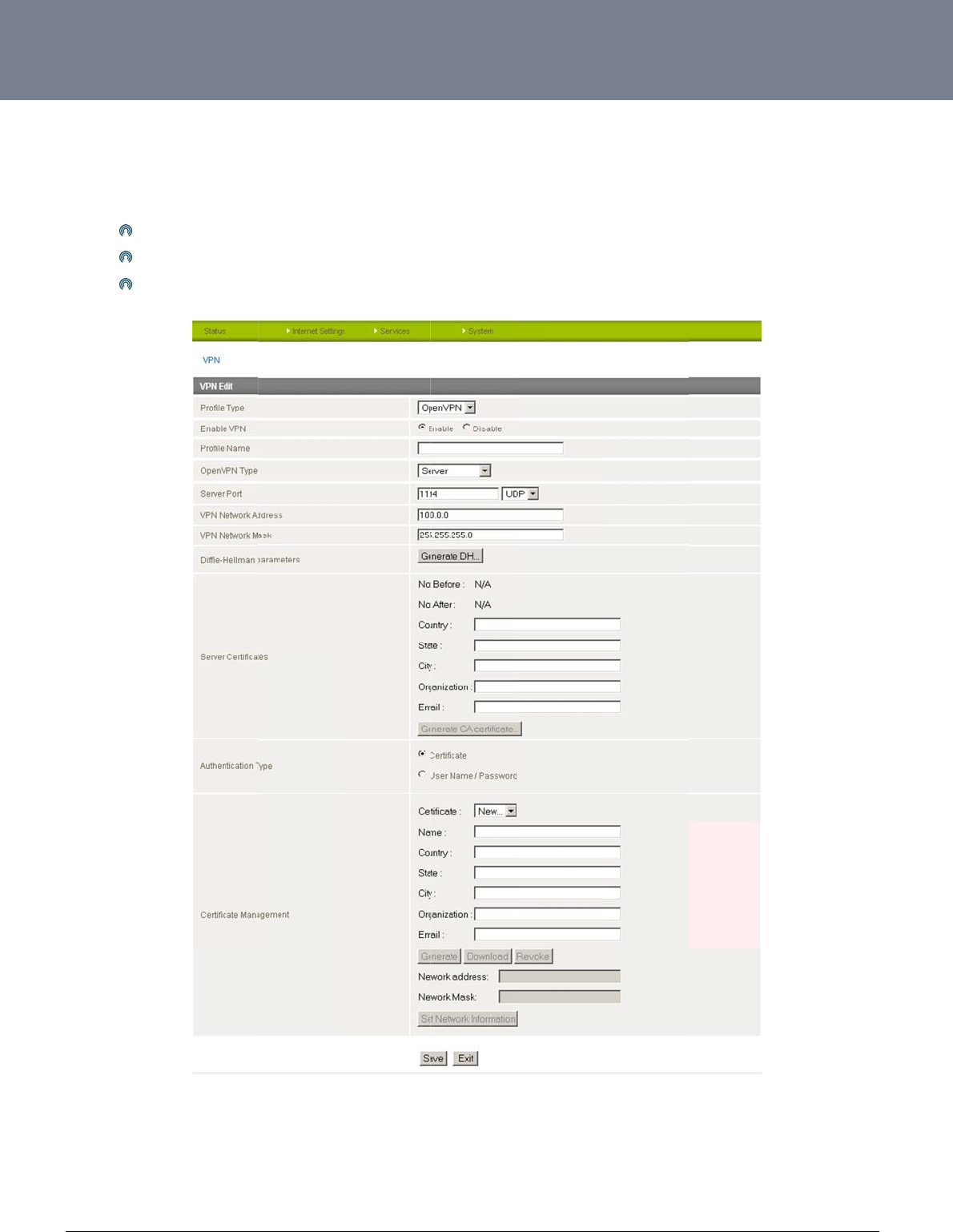
O
p
Ope
diffe
L
6908
w
.netcommwireless.c
p
enVPN
nVPN is an open so
u
rent OpenVPN mod
e
O
p
O
p
O
p
c
om
u
rce virtual private n
e
e
s:
p
enVPN Serve
r
p
enVPN Clien
t
p
enVPN Pee
r
-to-Pee
e
twork (VPN) progra
m
r VPN connection.
m
for creating point-t
o
o-point or server-to-
m
Figure43:Intern
e
m
ulti-client encrypte
d
e
tSettings‐Open
V
d
tunnels between ho
V
PN
NTC-6000 Series
U
o
st computers. The
N
U
ser Guide
TC-6000 supports t
h
h
ree

NTC-6000 Series – Industrial M2M Wireless Routers YML6908
32
www.netcommwireless.com
NETCOMM CALLDIRECT™ SERIES – NTC-6000 Series
ITEM DEFINITION
Profile Type Set this option to OpenVPN to create an OPenVPN VPN tunnel.
Enable VPN Enable or Disable the VPN connection.
Profile Name A name that can be used to identify the VPN connection.
OpenVPN Type Select the type of OpenVPN session to use. Options include Server, Client or Peer-to-Peer
Server Port Enter the port number the OpenVPN connection is to run on.
VPN Network Address Enter the network address for use on the VPN connection.
VPN Network Mask Enter the network mask for use on the VPN connection.
Diffie-Hellman parameters Generate the server and client keys used by the VPN connection.
Server Certificates Enter the applicable details to identify the OpenVPN server and create a CA certificatebased on this information.
Authentication Type Select the type of authentication in use for the VPN connection. You can select from a Certificate or Username
and Password combination.
Table8:InternetSettings‐VPN–OpenVPNFields
YM
L
ww
w
33
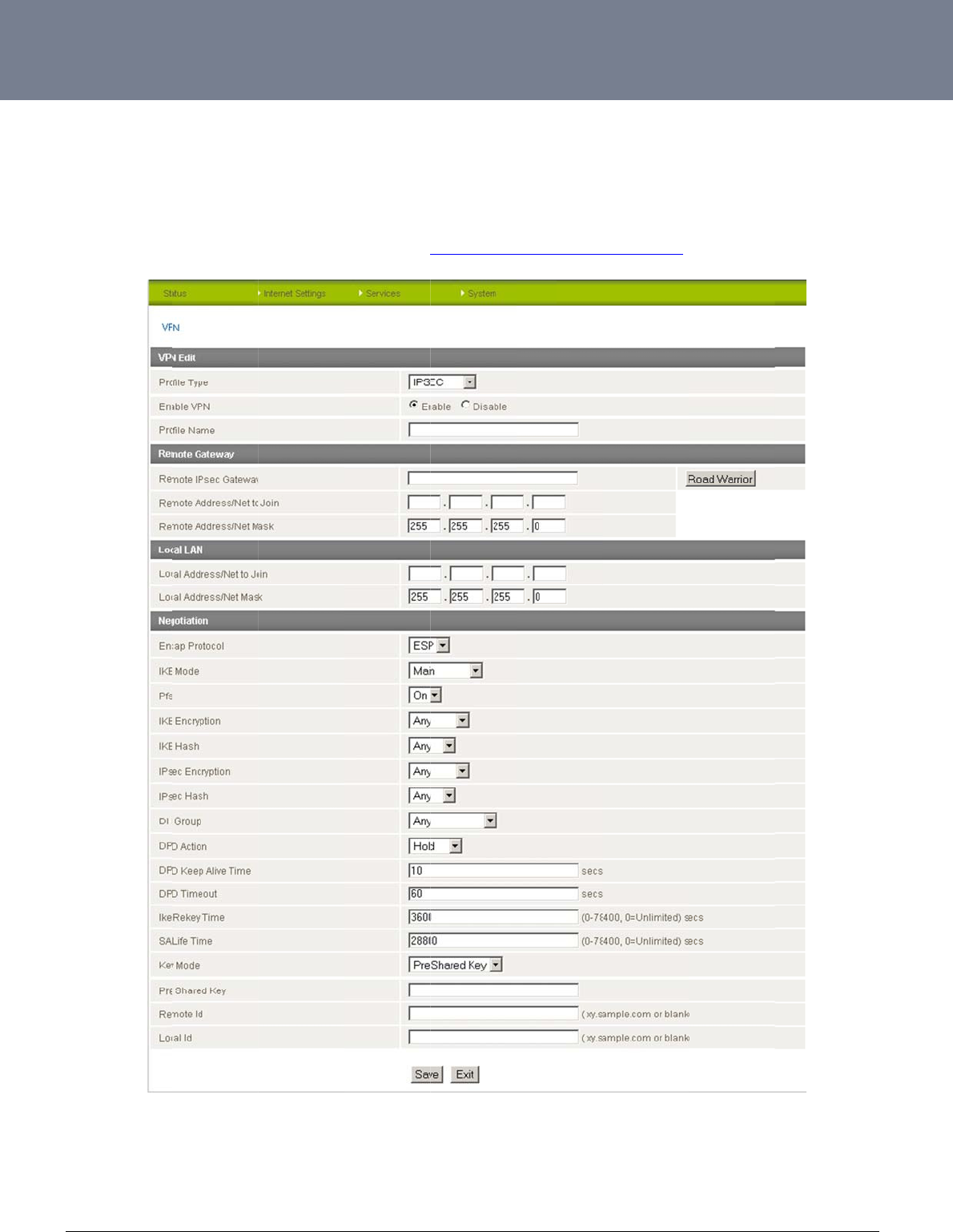
IP
S
IPS
e
rout
e
A W
Ple
a
L
6908
w
.netcommwireless.c
S
ec
e
c operates on Layer
e
rs support IPsec en
h
ite Paper with full I
n
se see the table on t
c
om
r
3 of the OSI model
a
d points and can be
n
structions on config
u
he following page fo
a
nd as such can pro
t
configured with Site
u
ring an IPSec VPN t
r details of the IPSe
c
t
ect higher layer pro
t
to Site VPN tunnels
w
unnel is available at
Figure44:VPN‐
fields shown above.
t
ocols. IPSec is used
w
ith other NTC-6000
s
http://support.netco
m
IPSecConfiguratio
n
.
for both Site to Site
V
s
or third party VPN
r
m
mwireless.com/pro
d
n
Settings
V
PN and Remote Ac
c
r
outers.
d
uct/m2m/ntc-6000
NTC-6000 Series
U
cess VPN. The NTC
-
U
ser Guide
6000 Series Cellular

NTC-6000 Series – Industrial M2M Wireless Routers YML6908
34
www.netcommwireless.com
NETCOMM CALLDIRECT™ SERIES – NTC-6000 Series
ITEM DEFINITION
Profile Type Set this option to IPSec.
Enable VPN Enable or Disable the VPN connection.
Profile Name A name that can be used to identify the VPN connection.
Remote IPSec Gateway The IP address that the IPSec server is running on.
Road Warrior Click this to configure the VPN connection for Road Warrior (connection from a dynamic IP Address) use.
Remote Address/Net to Join Enter the Remote IP address or Network for use on the VPN connection.
Remote Address/Net Mask Enter the subnet mask in use on the remote network.
Local Address/Net to Join Enter the Local IP address or Network for use on the VPN connection.
Local Address/Net Mask Enter the subnet mask in use on the local network.
Encap Protocol Select the encapsulation protocol to use with the VPN connection.
IKE Mode Select the IKE mode to use with the VPN connection.
PFS
Select whether or not to use PFS (Perfect Forward Secrecy) for the VPN connection. This feature will make sure
the same key is not generated twice and forces a new diffie-hellman key exchange. Both VPN endpoints must
support this function in order for it to work.
IKE Encryption Select the IKE (IPSec Key Exchange) encryption type to use with the VPN connection.
IKE Hash Select the IKE Hash type to use for the VPN connection.
IPSec Encryption Select the IPSec encryption type to use with the VPN connection.
IPSec Hash Select the IKE Hash type to use for the VPN connection.
DH Group Select the Diffie-Hellman group the VPN tunnel will use.
DPD Action Select the appropriate DPD (Dead Peer Detection) Action to use when the VPN tunnel detects a peer dropping
the VPN tunnel connection.
DPD Keep Alive Time Enter the time in seconds for DPD to keep alive.
DPD Timeout Enter the time in seconds for DPD to timeout.
IKE Rekey Time Enter the appropriate IKE Rekey time for the VPN connection.
SA Life Time Enter the appropriate SA (Security Association) Life time for the VPN connection.
Key Mode Select the type of key mode in use for the VPN connection. You can select from: Pre Shared Key, RSA Keys or
Certificates
Table9:InternetSettings‐VPN–IPSecDetails
YM
L
ww
w
35
R
o
Co
n
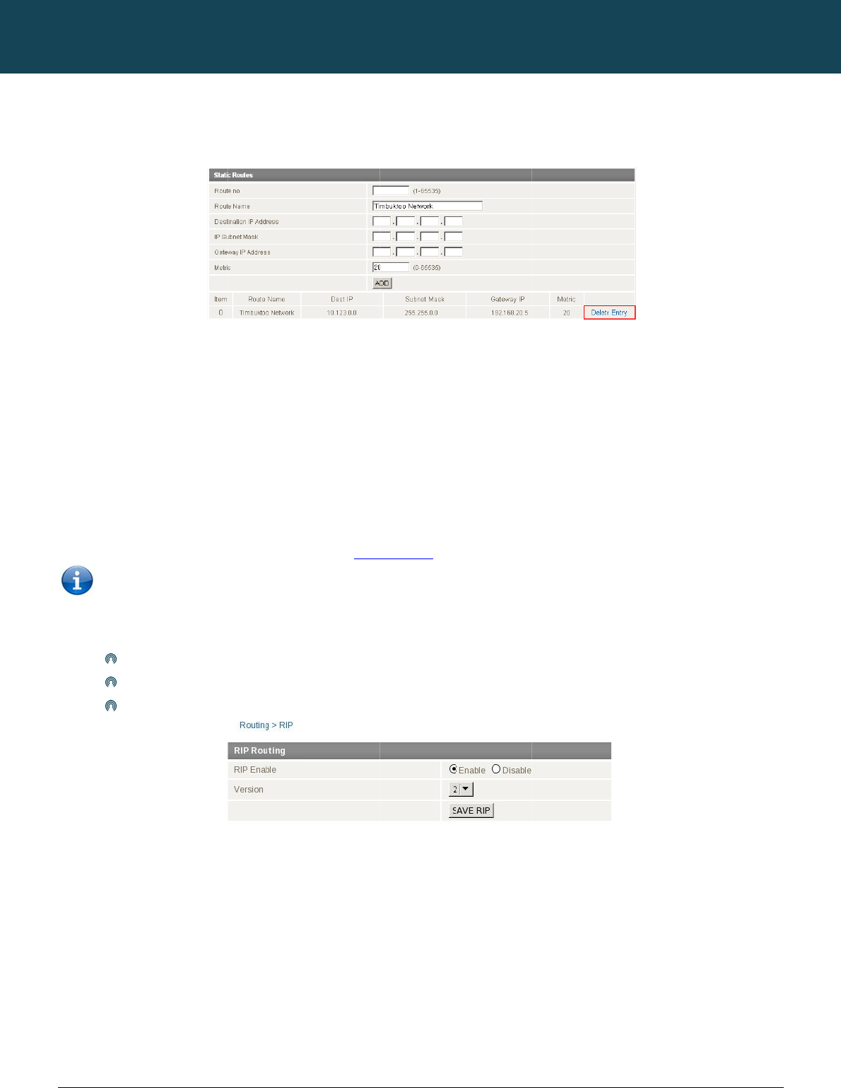
This
So
m
obt
a
Ho
w
Ad
d
The
Exa
m
If yo
ent
e
The
L
6908
w
.netcommwireless.c
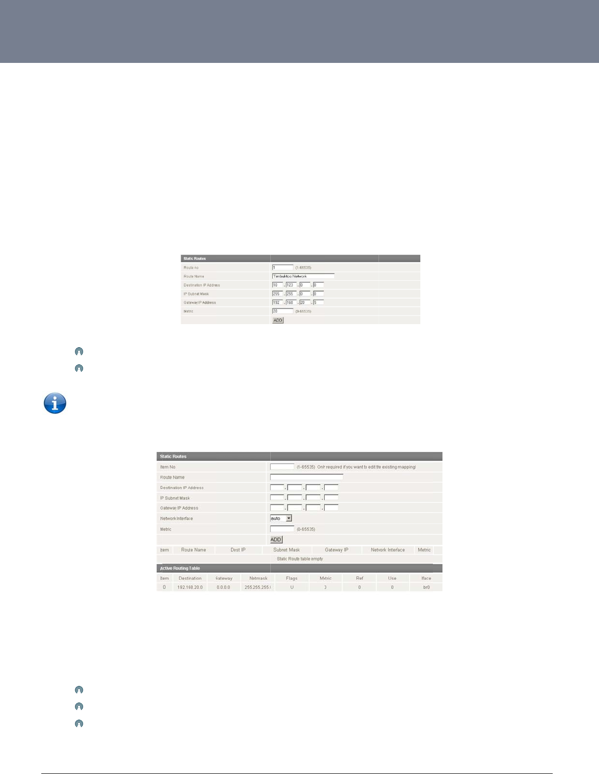
o
uting Con
n
figuring Static
facility is available
b
m
e routes are added
b
a
ining a WAN PPP co
w
ever, if you have oth
d
ing Static Rou
t
Enter
Click
NOTE: You mu
s
Active Routing table
m
ple:
u have another rout
e
r:
10.12
255.2
192.1
lower the metric val
u
c
om
figuration
Routes
b
y clicking on the “In
t
b
y the router automa
o
nnection.
er routers (hence ne
t
t
es
the values in the fiel
d
the ADD button.
s
t increment the “Ro
u
at the bottom of the
e
r on the Ethernet sid
3.0.0 in the Destinati
55.0.0 in the IP Sub
n
68.20.5 in the Gate
w
u
e the higher the pri
o
t
ernet Settings” befo
r
tically on a connecti
o
t
works) on the Ether
n
d
s as above.
u
te no” by 1 for each
screen will show the
e of the router with a
on IP address field.
n
et Mask field.
w
ay IP address field.
o
rity this route has ov
e
r
e selecting “Routing
o
n initialization such
a
n
et subnet for exam
p
route in the “Route
n
new route added as
gateway of 192.168
e
r other routes.
” followed by the “St
a
as the Ethernet sub
n
p
le, you may want to
a
Figure4
n
o” field otherwise th
a
s
shown at the botto
m
.20.5 that interfaces
Figure4
6
a
tic” menu item on t
h
n
et route for routing t
o
a
dd some more stati
5:AddingStaticRo
a
t route will be over
w
m
of the screenshot
b
to network 10.123.0.
0
6
:StaticRouteEntr
y
h
e right.
o
a device on an Eth
e
c
routes.
u
tes
w
ritten.
elow:
0
/16 and you want t
o
y
NTC-6000 Series
U
e
rnet subnet. A PPP
o
get to a device on t
U
ser Guide
r
oute is also added
u
hat network then yo
u
u
pon
u
NT
C
36
ww
w
De
l
Sel
e
H
o
RIP
For
e
Eth
e
You
To
e
C
-6000 Series – Indu
s
w
.netcommwireless.c
eting Static Ro
u
ct the “Delete Entry”
o
w to Con
f
(
Routing Information
e
xample, the route f
o
e
rnet subnet.
will have to add the
r
NOTE: it is pos
s
nable RIP click on t
h
Set th
Selec
Click
s
trial M2M Wireless
R
c
om
u
tes
text (in blue) for the
f
igure RIP
Protocol) is used fo
r
o
r the route
r
’s Ethern
e
routes appropriately
s
ible that some route
h
e “Internet Settings”
e Enable RIP option
t the RIP version you
Save RIP
R
outers
route as shown in th
e
r
advertising routes t
o
e
t subnet could be a
d
in the Static Routes
s
rs will ignore RIP.
menu followed by “
R
to Enable.
wish to use.
e
figure above.
o
other routers. Thus
d
vertised to a Route
r
s
ection – see
A
ddin
g
R
outing“ and then th
e
NETCOMM
all the routes in the
r
r
on the PPP interfac
e
g
Static Routes
.
e
“RIP” menu item o
n
Figure4
CALLDIRECT™
Figure47:De
l
r
oute
r
’s routing table
e
side so that a Rout
e
the right.
8:InternetSetting
s
SERIES – NT
C
l
etingaStaticRout
e
will be advertised to
e
r on this network wil
‐Routing–RIP
C
-6000 Serie
e
Entr
y
other nearby router
s
ll know how to route
t
YML6908
s
s
.
t
o a device on the ro
ute
r
’s
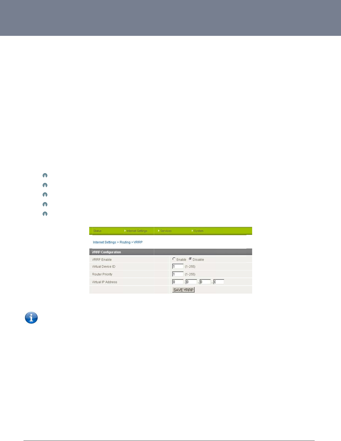
YM
L
ww
w
37
H
o
The
sub
n
inst
e
Two
beh
a
call
e
Mas
A vi
r
This
To
e
L
6908
w
.netcommwireless.c
o
w to Con
f
Virtual Router Redu
n
n
et. This increased r
e
e
ad of one physical r
o
or more physical ro
u
a
lf of the virtual route
e
d the master router.
ter routers have a pr
i
r
tual router must use
address is used by
o
nable VRRP click on
Click
Enter
Enter
Enter
Click
NOTE: Con
f
or on a co
m
c
om
f
igure VRR
n
dancy Protocol (VR
R
e
liability is achieved
o
uter.
u
ters are then config
u
r fails, an arrangem
e
iority of 255 and bac
00-00-5E-00-01-XX
a
o
nly one physical ro
u
the “Internet Setting
Enable to activate V
R
an ID – this is the V
R
a priority – a higher
v
the VRRP IP addres
s
Save VRRP
f
iguring VRRP chan
g
m
mand prompt type:
P
R
P) is a non-propriet
a
by advertising a “virt
u
red to stand for the
e
nt is made for anoth
e
kup router(s) can ha
v
a
s its (MAC) addres
s
u
ter at a time, and is
s” menu followed by
R
RP.
R
RP ID which is diffe
r
v
alue is a higher pri
o
s
– this is the virtual I
g
es the MAC addres
s
arp –d <ip address
>
a
ry redundancy prot
o
ual router” (an abstr
a
virtual router, with o
n
e
r physical router to
v
e priority between 1
s
. The last byte of the
the only way that oth
“Routing” and then
t
r
ent for each virtual r
o
o
rity.
P address that both
v
s
of the Ethernet port
>
(i.e. arp –d 192.16
8
o
col designed to inc
r
a
ct representation of
n
ly one doing the act
automatically replac
e
and 254.
e
address (XX) is the
h
er physical routers
c
t
he “VRRP” menu ite
m
o
uter on the network
v
irtual routers share.
Figure49:In
t
and therefore if you
8
.1.1) to clear the ar
p
r
ease the availability
master and backup
ual routing at any gi
v
e
it. The physical rou
Virtual Router Identif
c
an identify the mast
e
m
on the right.
t
ernetSettings‐Ro
u
want to resume with
p
cache.(old MAC ad
d
and reliability of the
d
routers acting as a
g
v
en time. If the curre
n
ter that is currently f
o
i
er (VRID), which is
d
e
r router within a virt
u
u
ting–VRRP
the web configurati
o
d
ress).
NTC-6000 Series
U
default gateway ser
v
g
roup) as a default g
a
n
t physical router th
a
o
rwarding data on b
e
d
ifferent for each virt
u
u
al router.
o
n you must use the
n
U
ser Guide
v
icing hosts on the s
a
a
teway to the host(s)
t is routing the data
o
e
half of the virtual ro
u
u
al router in the netw
o
n
ew IP address (VR
R
a
me
o
n
u
ter is
o
rk.
R
P
IP)
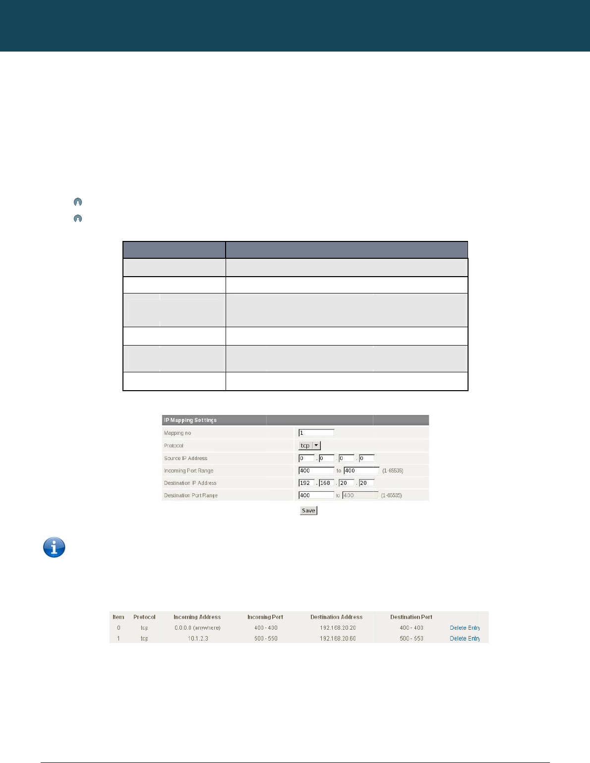
NT
C
38
ww
w
N
A
This
ena
b
com
Ho
w
This
Ex
a
Con
f
To
d
C
-6000 Series – Indu
s
w
.netcommwireless.c
A
T configu
facility is available
b
b
led by default port f
puter or service with
w
to Configure
P
is only needed if yo
u
Enter
Click
a
mple:
Note: If the
port numb
e
f
igured mappings ar
e
d
elete a port forwardi
n
s
trial M2M Wireless
R
c
om
ration
b
y clicking on the “In
t
f
orwarding may be n
e
in a private local-are
P
ort Forwardin
g
u
need to map inbou
the information as a
p
Save
S
o
Inc
o
Des
t
Des
t
“Incoming Port Ran
g
e
rs then the “Destina
t
e
displayed shown i
n
ng rule, click on the
c
R
outers
t
ernet Settings” men
u
e
cessary to use som
e
a network (LAN).
g
nd requests to a spe
p
propriate accordin
g
ITEM
Item No.
Protocol
o
urce IP Address
o
ming Port Range
t
ination IP Address
t
ination Port Range
g
e” specifies a singl
e
t
ion Port Range” MU
S
n
the screenshot bel
o
c
orresponding “Del
e
u
followed by “Routin
e
applications and d
cific port on the WA
N
g
to the guidelines b
e
1 to as many as
Options include
T
Specifies either a
0.0.0.0 that allow
s
Enter the Exter
Enter the Local
A
Enter the Local A
r
Table10:Inter
n
Figure50:Inter
n
e
port (as above) the
n
S
T be the same as th
o
w:
Figure51:Confi
g
te Entry” link from th
e
NETCOMM
n
g” and then the “NA
T
evices over the inter
N
IP address to a de
v
e
low.
s
needed. Increment by on
e
T
CP, UDP, or All protocols
“Friendly” IP address that
s
all IP addresses to acce
s
r
nal port(s) to listen to.
Area Network Address of
d
rea Network Port(s) to for
w
n
etSettings‐Routi
n
n
etSettings‐Routi
n
n
the destination por
t
h
e “Incoming Port Ra
g
uredNATMappin
g
e
list of IP Mappings
CALLDIRECT™
T
” menu item on the
n
et. Port forwarding
a
v
ice connected on t
h
DEFINITION
e
for each port forwarding
is allowed to access the
s
s the router.
d
evice to forward inbound
w
ard connections to
n
g‐NATOptions
n
g‐NATExample
t
can be set
to any p
o
nge”.
g
s
.
SERIES – NT
C
right. The router is s
e
a
llows remote comp
u
e Ethernet interface,
rule.
router or a wildcard IP
a
requests to.
o
rt.
If the “Incoming
P
C
-6000 Serie
e
t to use NAT mode
b
u
ters or hosts to con
n
e.g. a web camera.
address of
Port Range” specifie
YML6908
s
b
y default. With NAT
n
ect to a specific
s
a range of
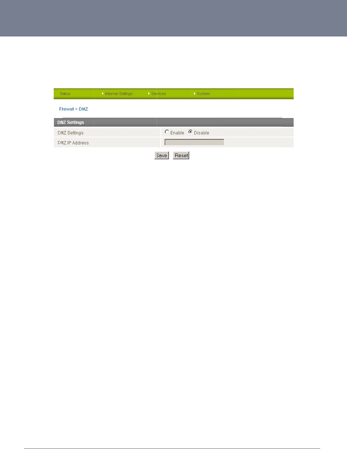
YM
L
ww
w
39
Ho
w
The
This
L
6908
w
.netcommwireless.c
w
to Configure
D
Demilitarized Zone (
facility is available
b
c
om
D
MZ
DMZ) enables a dev
b
y clicking on the “In
t
ice to utilize a direct
t
ernet Settings” men
u
Serv
connection to the W
A
u
followed by “Routin
Figure52:Inter
n
ices
Fe
a
A
N. This means any
n
g” and then the “DM
n
etSettings‐Routi
n
a
tur
es
incoming connectio
n
Z” menu item on the
n
g‐NAT
n
s are forwarded dire
right.
NTC-6000 Series
U
e
ctly to this device wi
U
ser Guide
th all ports open.
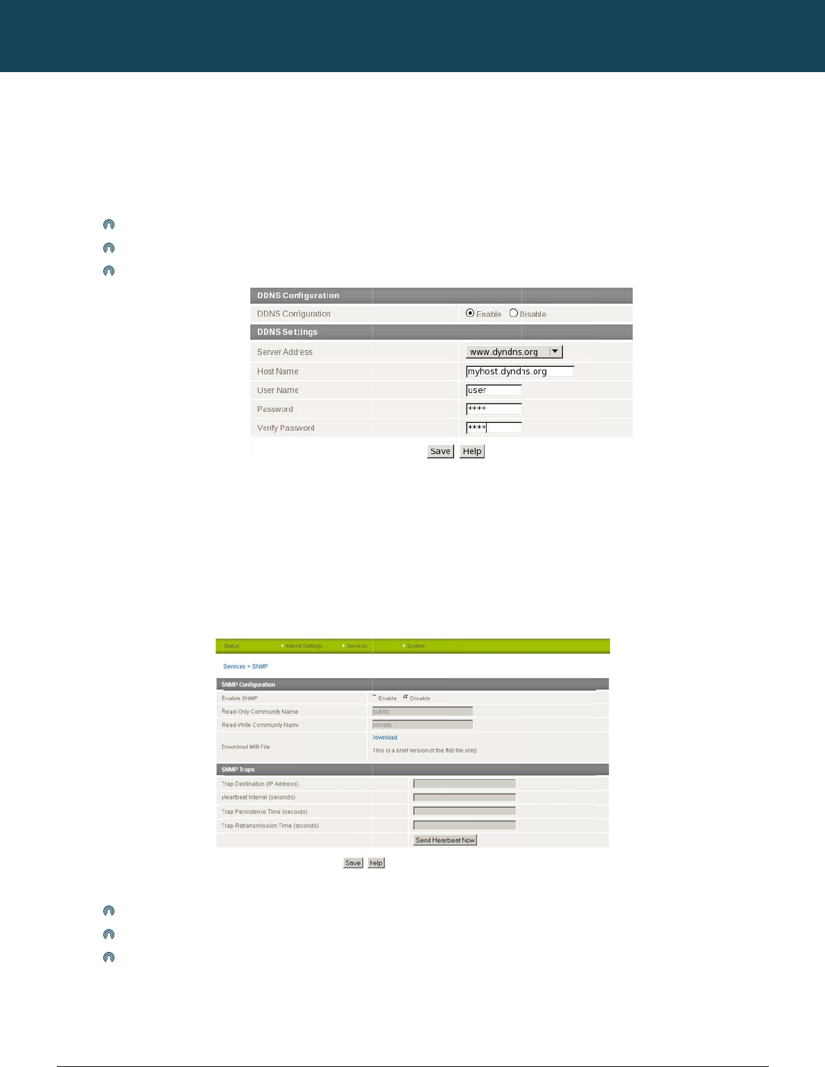
NT
C
40
ww
w
S
e
Ho
w
This
Dyn
a
Ho
w
This
SN
M
suc
h
To
c
SN
M
sho
u
writ
e
C
-6000 Series – Indu
s
w
.netcommwireless.c
e
rvices Fe
a
w
to Configure
t
facility is available
b
a
mic DNS provides
a
To co
Selec
Click
w
to configure
S
facility is available
b
M
P (Simple Network
M
h
as the signal stren
g
onfigure SNMP:
Click
Enter
Click
M
P mandates that th
e
u
ld always communi
c
e
(SET) operations.
s
trial M2M Wireless
R
c
om
a
tures
t
he Dynamic D
N
b
y clicking on the “S
e
a
method for the rout
e
nfigure dynamic DN
S
t the Dynamic DNS
s
Save
S
NMP
b
y clicking on the “S
e
M
anagement Protoc
o
g
th, the system time,
Enable
Community Names
o
Save.
e
SNMP agents shoul
c
ate with the agents
a
R
outers
N
S Client
e
rvices” menu follow
e
e
r to update an exte
r
S
set the DDNS Con
f
s
ervice that you wish
e
rvices” menu follow
e
o
l) is used to remotel
y
the interface status,
o
r leave them as def
a
d accept request m
e
a
long with the assoc
e
d by the “DDNS” m
e
r
nal name server wit
h
f
iguration option to E
n
to use. Enter your d
y
Figure53:Servi
c
e
d by the “SNMP” m
e
y
monitor the router f
o
etc.
a
ult
e
ssages only if the c
o
i
ated community na
m
NETCOMM
e
nu item on the right.
h
the current WAN IP
nable.
y
namic DNS accoun
t
c
es‐DynamicDNS
e
nu item on the right.
or conditions that m
a
Figure
o
mmunity string in th
m
e. The default SNM
CALLDIRECT™
address.
t
credentials.
a
y warrant administr
a
54:Services‐SNM
P
e
message matches
P
community names
SERIES – NT
C
a
tive attention. It can
P
its community name
are “public” for read
C
-6000 Serie
be used to retrieve i
n
e
. Therefore, the man
d
-only (GET) operatio
YML6908
s
n
formation from the
r
a
gement application
ns and “private” for
r
r
outer
r
ead-
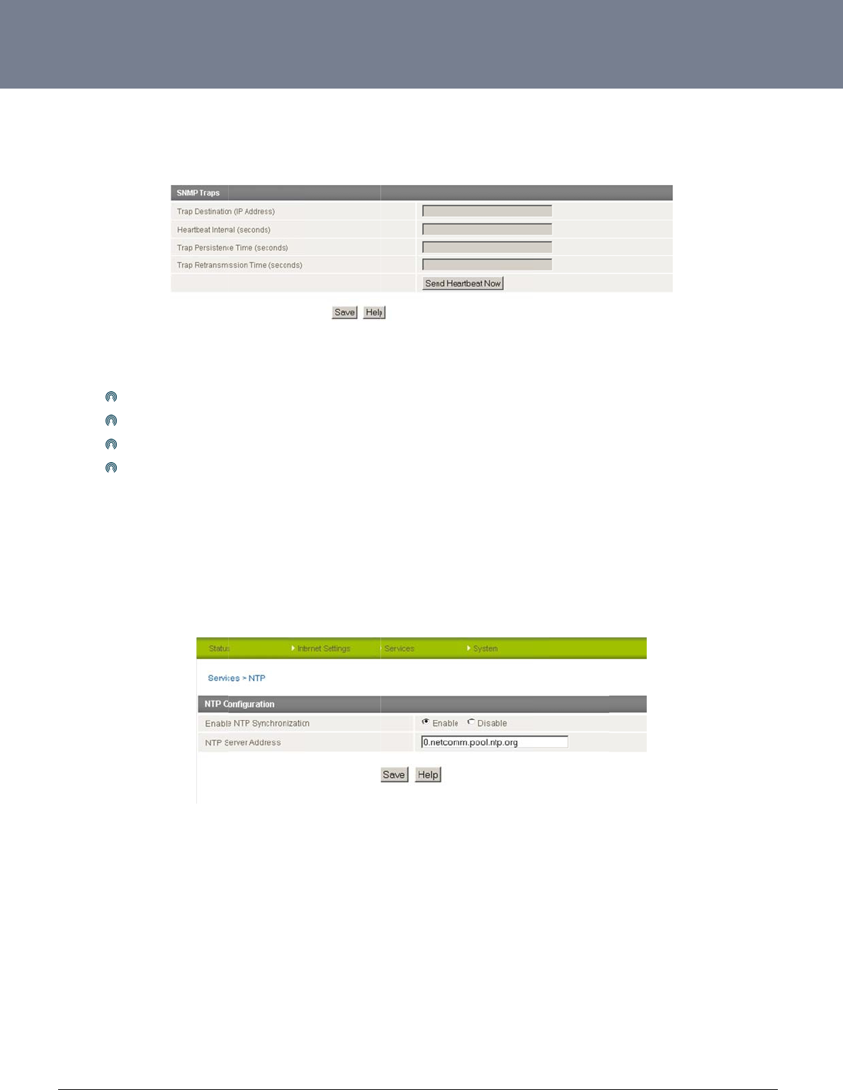
YM
L
ww
w
41
SN
M
The
con
n
Co
n
Ho
w
This
The
Log
L
6908
w
.netcommwireless.c
M
P Traps
SNMP Trap function
s
n
ected on the netwo
r
n
figuring the S
N
Enter
Heart
Trap
P
Trap
R
w
to Configure
N
facility is available
b
NTP (Network Time
P
entries and Firewall
s
c
om
s
to provide system
e
r
k. This helps to redu
N
MP Traps se
t
the Trap Destination
beat Interval – Enter
P
ersistence Time. –
E
R
etransmission Time
N
TP
b
y clicking on the “S
e
P
rotocol) settings all
o
s
ettings.
e
vent notifications to
ce the number of un
t
tings
IP Address – the ad
the time in seconds
E
nter the time in sec
o
– Enter the time to r
e
e
rvices” menu follow
e
o
w your router to syn
a SNMP server with
o
n
ecessary SNMP re
q
dress of the object t
h
b
etween which a mu
o
nds that the trap wil
l
e
send notifications o
n
e
d by the “NTP” men
u
c
hronize the NTC-6
0
o
ut solicitation so tha
q
uests across a net
w
h
at generates the tra
u
lticast Heartbeat not
l persist before timin
g
n a retransmission q
u
u item on the right.
0
00 router’s internal
c
F
t the SNMP server d
o
w
ork and reduces net
w
Figure55:Ser
v
p.
ification message is
g
out
u
eue.
c
lock
w
ith a global In
t
F
igure56:Services
‐
o
es have to request i
w
ork traffic and reso
u
i
ces‐SNMPTraps
g
enerated.
t
ernet Time server. T
h
NTP
NTC-6000 Series
U
i
nformation from eac
urces
his setting will affect
U
ser Guide
h
and every device
functions such as S
y
y
stem
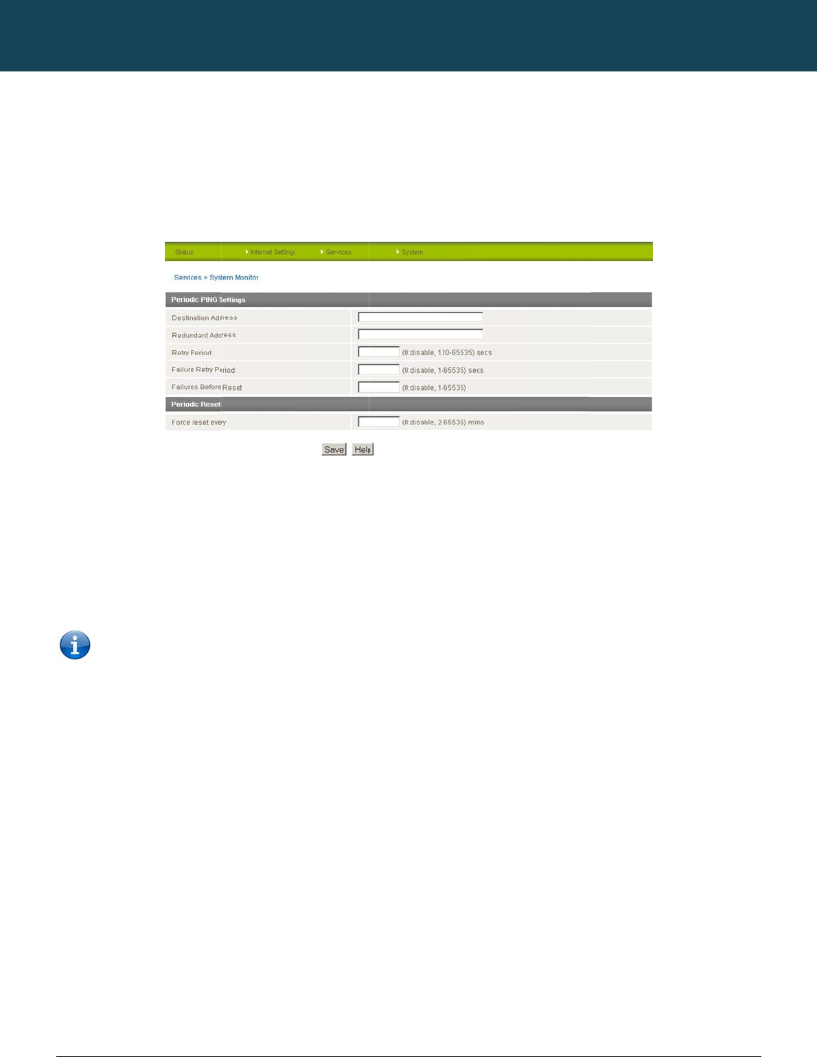
NT
C
42
ww
w
Ho
w
This
The
will
r
This
1.
2.
3.
4.
5.
C
-6000 Series – Indu
s
w
.netcommwireless.c
w
to Configure
t
facility is available
b
Periodic Ping Reset
r
eboot.
works as follows:
After every “Perio
d
If all 3 pings fail t
h
The router then s
e
If all accelerated
p
If any ping succ
Note: The “
s
trial M2M Wireless
R
c
om
t
he Periodic Pin
b
y clicking on the “S
e
Monitor configures t
h
d
ic Ping Timer” confi
h
e router sends 3 co
n
e
nds 3 consecutive
p
p
ings in step C abov
e
eeds the router retu
r
Periodic Ping Timer”
R
outers
g Reset Monito
r
e
rvices” menu follow
e
h
e router to transmit
c
gured interval, the r
o
n
secutive pings to th
e
p
ings to the “Destinat
e
fail the number of t
r
ns to step 1 and do
e
should never be set
r
e
d by the “System M
o
c
ontrolled ping pack
e
o
uter sends 3 conse
c
e
“Second Address”
.
ion Address” and 3
c
imes configured in “
F
s not reboot.
to a value less than
NETCOMM
o
nitor” menu item on
k
ets to 1 or 2 user sp
e
Figure5
c
utive pings to the “
D
.
c
onsecutive pings to
F
ail Count”, the rout
e
60 seconds; this is t
o
CALLDIRECT™
the right.
e
cified IP addresses
.
7:Services‐Syste
m
D
estination Address”.
the “Second Addre
s
e
r reboots.
o
allow the router tim
SERIES – NT
C
Should the router n
o
m
Monito
r
s
s” every “Periodic Pi
e
to reconnect to the
C
-6000 Serie
o
t receive responses
ing Accelerated Tim
e
e
cellular network foll
o
YML6908
s
to the pings, the ro
u
e
r” configured interv
a
o
wing a reboot.
u
ter
a
l.
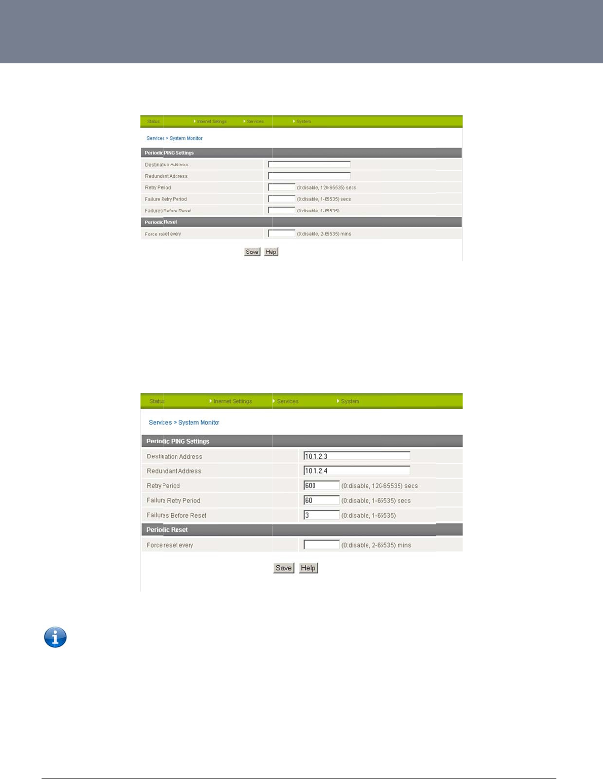
YM
L
ww
w
43
Pe
r
To
d
Pe
r
An
E
The
atte
m
L
6908
w
.netcommwireless.c
r
iodic Ping Disa
d
isable the Periodic
P
r
iodic Ping Ena
b
E
xample Setup:
setup below will pin
g
m
pts at the one minu
NB: The tra
f
c
om
bled
P
ing Reset Monitor si
m
b
led
g
10.1.2.3 every 10
m
te interval fails, the r
o
ffic generated by th
e
m
ply set to “Fail Cou
m
inutes, if it fails it th
e
o
uter will reboot.
e
periodic ping featu
r
nt” 0
e
n tries to ping 10.1.
2
Figure59:Exam
p
r
e is counted as cha
r
Figure58:Servi
2
.4, if that also fails it
p
lePeriodicPingS
e
r
geable usage, plea
s
c
es‐SystemMonit
o
then accelerates th
e
e
tup
s
e keep this in mind
w
or
e
ping attempts to on
w
hen selecting how
o
NTC-6000 Series
U
n
ce every 60 second
s
o
ften to ping.
U
ser Guide
s
and if 3 successiv
e
e
ping
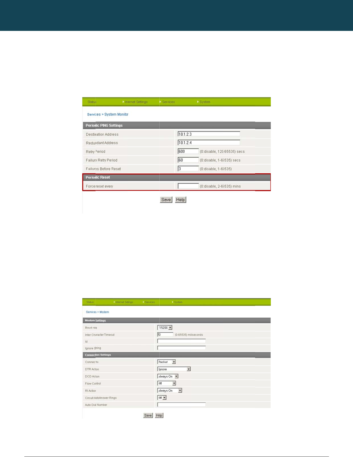
NT
C
44
ww
w
Ho
w
This
The
reb
o
Ho
w
This
The
of e
m
The
C
-6000 Series – Indu
s
w
.netcommwireless.c
w
to Configure
a
facility is available
b
router can be config
o
ot if some anomaly
o
w
to
Configur
e
t
facility is available
b
modem can be utiliz
m
bedded systems u
t
modem settings can
s
trial M2M Wireless
R
c
om
a
Periodic Rese
b
y clicking on the “S
e
ured to automaticall
y
o
ccurs. The default v
he Modem Setti
n
b
y clicking on the “S
e
ed to communicate
w
t
ilizing serial port co
n
be adjusted if requi
r
R
outers
t Timer
e
rvices” menu follow
e
y
reboot after a perio
d
alue is 0 which disa
b
n
gs
e
rvices” menu follow
e
w
ith serial devices vi
a
n
nections.
r
ed to match your se
e
d by the “System M
o
d
ic interval specified
b
les the Periodic Res
e
d by the “Modem”
m
a
the DE-9 connecto
r
rial device settings.
NETCOMM
o
nitor” menu item on
d
in minutes. While th
s
et Timer. The maxim
Figure6
0
m
enu item on the rig
h
r on the router. This
e
Figu
r
CALLDIRECT™
the right.
is is not necessary, i
t
um value is 65535
m
:Services‐System
M
h
t.
e
nables the router to
r
e61:Services‐M
o
SERIES – NT
C
t
does ensure that in
inutes.
M
onito
r
communicate with r
e
o
dem
C
-6000 Serie
the case of remote i
e
mote monitoring sy
s
YML6908
s
n
stallations, the rout
e
s
tems, as well as a v
a
er
will
a
riety
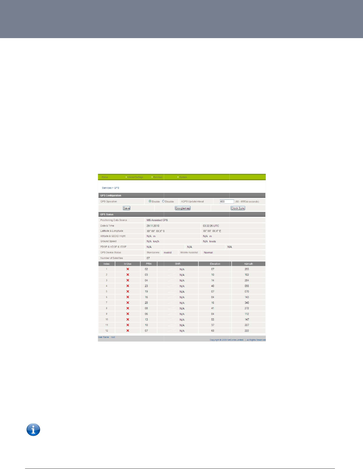
YM
L
ww
w
45
G
P
This
The
The
(HD
O
Sel
e
Clic
k
The
GP
S
Bec
a
time
MS
A
L
6908
w
.netcommwireless.c
P
S
facility is available
b
built-in GPS module
GPS Status window
p
O
P) and vertical dilu
t
ct to “Enable” GPS
O
k
“Save” to save you
r
“GoogleMap” butto
n
S
service.
a
use GPS positionin
g
. This ensures you w
A
ssisted GPS enabl
e
Please note
:
c
om
b
y clicking on the “S
e
enables you to utiliz
e
provides up to date i
t
ion of precision (VD
O
O
peration and an ap
p
r
GPS settings.
n
provides a quick sh
g
relies on accurate
c
ill always have the c
o
e
s the
r
outer to quick
:
The GPS functionali
e
rvices” menu follow
e
e
location based ser
v
nformation about th
e
O
P)) of the router.
p
ropriate update int
e
ort cut to show your
c
lock settings to obt
a
o
rrect GPS position i
n
ly and efficiently obt
a
ty is available in the
e
d by the “GPS” men
v
ices, keep track of
h
e
current location an
d
rval depending on h
o
routers current positi
a
in the correct infor
m
n
formation available.
a
in location informati
o
NTC-6908 and NTC-
n
u item on the right.
h
ardware out in the fi
d
the current GPS si
g
ow quickly you woul
d
i
on on a map, while
t
m
ation about your loc
a
o
n by querying the c
-
6908S only, from fir
m
eld or find your curr
e
g
nal conditions (posi
t
d
like the current GP
S
Figure6
2
t
he “Clock Sync” but
t
a
tion, the “Clock Syn
ellular network for c
u
m
ware version 1.6.0
o
e
nt location.
ion dilution of precis
i
S
position informatio
n
2
:Services–GPS
t
on enables you to q
u
c
” button enables yo
u
rrent GPS satellite a
n
o
nwards.
NTC-6000 Series
U
ion (PDOP), horizont
n
updated.
u
ickly synchronize t
h
o
u to quickly set the
r
nd location informati
o
U
ser Guide
a
l dilution of precisi
o
e router time from th
e
r
oute
r
clock to the co
o
n.
o
n
e
rrect

NT
C
46
ww
w
S
M
The
You
Basi
SM
Gen
C
-6000 Series – Indu
s
w
.netcommwireless.c
M
S Tools
SMS tools applicatio
can also utilize this f
c functionality supp
o
Abilit
y
Abilit
y
Abilit
y
Abilit
y
Abilit
y
Abilit
y
S Tools Setup
eral SMS functionalit
y
s
trial M2M Wireless
R
c
om
o
n has been develop
e
f
unctionality to read
a
o
rted:
y
to send a text mes
s
y
to receive a text m
e
y
to forward incomin
g
y
to read run-time va
r
y
to change live conf
i
y
to execute support
e
y is enabled by defa
Numb
e
Encoding Sche
m
SMSC Address
Redirect to Mo
b
Redirect to TC
P
TCP Port to Re
d
Redirect to UD
P
UDP Port to red
Enable Remote
R
outers
e
d to include basic
S
a
nd change run-time
s
age via a 3G netwo
r
e
ssage via a 3G net
w
g
text messages via
a
r
iables from the devi
c
i
guration on the devi
c
e
d commands (e.g.
r
ult. You can open th
e
ITEM
e
r of Messages / Page
m
e
b
ile
P
d
irect
P
irect
Diagnostics
S
MS functionality suc
variables on the rou
t
k and store in perm
a
w
ork and store in per
m
a
3G network to anot
h
c
e (e.g. uptime) and
c
e (e.g. connection
A
r
eboot).
e
Setup page in ord
e
Figure63:Servi
c
Enter the numb
e
Select the encodi
The short messa
g
Forward incomin
g
Forward incomin
g
The TCP port on
w
Forward incomin
g
The UDP port o
n
Enable diagnosti
c
Figure64:SMS
S
NETCOMM
c
h as sending a mes
s
t
er.
a
nent storage.
m
anent storage.
her remote destinati
o
send the result to a
r
A
PN).
e
r to configure additi
o
c
es‐SMS‐Setup
e
r of SMS messages to di
s
ng method used for SMS
m
g
e service center (SMSC)
a
g
text messages to the re
m
g
text messages to the re
m
w
hich to connect to the re
m
g
text messages to the re
m
n which to connect to the
r
c
s to be performed by a s
p
S
etupConfiguratio
n
CALLDIRECT™
s
age, receiving a me
o
n which may be a T
C
r
emote destination
w
o
nal settings. To do t
DEFINITION
s
play per page.
m
essages.
a
ddress is the number of y
o
m
ote destination defined.
m
ote TCP destination defin
e
m
ote destination on.
m
ote UDP destination defin
e
r
emote destination on.
p
ecially crafted SMS mess
a
n
Items
SERIES – NT
C
s
sage and redirectin
C
P/UDP server or ot
h
hich may be a TCP/
U
h
is, click on “Servic
e
o
ur mobile broadband SM
S
e
d.
e
d.
a
ge.
C
-6000 Serie
n
g an incoming mes
s
h
er mobile device.
U
DP server or other
m
e
s”, then “SMS” and
t
S provider.
YML6908
s
age to another desti
n
m
obile device.
t
hen “Setup”.
n
ation.

YM
L
ww
w
47
SM
Inc
o
R
e
d
You
del
e
For
E
R
e
d
You
mes
The
For
E
at th
SM
En
a
Ena
b
If R
e
L
6908
w
.netcommwireless.c
S Configuration
ming text messages
d
irect to
M
obil
e
can forward incomi
n
te the number in the
E
xample: If someon
e
d
irect to TCP
&
can also forward inc
sage.
TCP/UDP address c
a
E
xample: If someon
e
e same time.
S Configuration
a
ble Remote D
i
b
le or disable the Re
e
mote Diagnostics c
o
Please not
e
operation.
It is highly re
c
c
om
n
for Redirection
can be redirected t
o
e
n
g text messages to
a
‘Redirect to Mobile”
e
sends a text messa
g
&
TCP Port, Re
c
oming text message
a
n be an IP address
e
sends a text messa
g
n
for Remote Di
a
i
agnostics
mote Diagnostics fe
a
o
mmands are found,
e
: It is possible to adj
c
ommended to ena
b
o
another mobile dev
a
different destinatio
n
field and click the “
S
g
e and Redirect to
M
direct to UDP
s to a TCP/UDP bas
e
or domain name. Th
g
e and Redirect to T
a
gnostics
a
ture. If this setting i
s
the router executes
t
ust settings and pre
v
b
le security when utili
ice and/or a TCP/U
D
n
number. This desti
n
S
ave” button.
M
obile is set to “0412
3
&
UDP Port
e
d destination. The T
e
port number rang
e
CP is set to “192.16
8
s
enabled all incomin
t
hose commands. T
h
v
ent your router from
sing this feature.
D
P message server.
n
ation number can b
345678”, this text m
e
T
CP or UDP server c
a
e
is from 1 to 65535.
P
8
.20.3” and “2002”, t
h
n
g text messages ar
e
h
is feature is disable
d
functioning correctl
y
e another mobile ph
o
e
ssage is stored on t
h
a
n be any kind of pu
b
P
lease refer to your
T
h
is text message is
s
e
parsed and tested
f
d
by default.
y
. If this occurs, you
w
o
ne or 3G router pho
h
e router and forwar
d
b
lic or private server
T
CP/UDP based SM
S
t
ored in the router a
n
o
r if they contain Re
m
w
ill need to perform
a
NTC-6000 Series
U
o
ne number. To disa
b
d
ed to “0412345678
”
if the server accept
s
S
server configuratio
n
n
d forwarded to “19
2
m
ote Diagnostics co
m
a
factory reset in ord
U
ser Guide
b
le the feature, simpl
y
”
at the same time.
s
incoming text-base
d
n
for which port to us
.168.20.3” on port “
2
m
mands.
e
r to restore normal
y
d
e.
2
002”
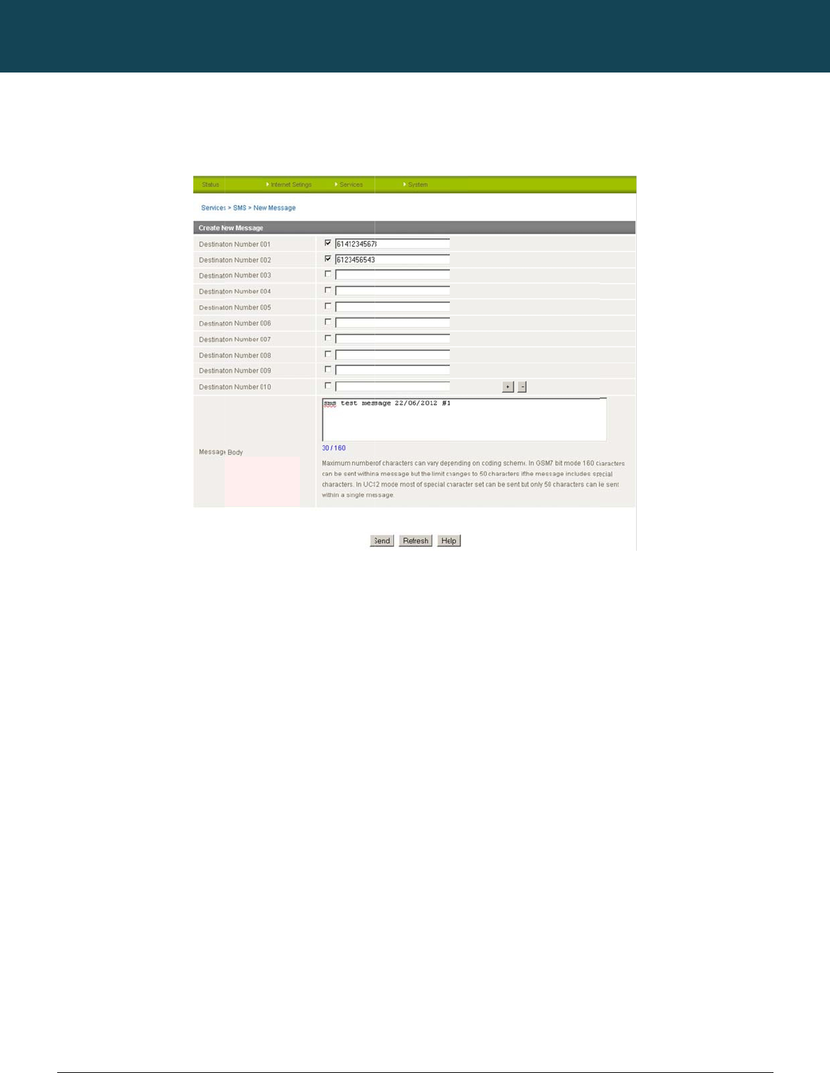
NT
C
48
ww
w
SM
The
A n
e
“Fail
By
d
You
Afte
r
C
-6000 Series – Indu
s
w
.netcommwireless.c
S - New Messa
g
New Message page
e
w SMS message ca
n
ure” (in red).
d
efault 10 recipient e
n
can select to enable
r
entering the appro
p
s
trial M2M Wireless
R
c
om
g
e
can be used to sen
d
n
be sent to a maxi
m
n
try fields are shown
e
or disable individua
p
riate recipient num
b
R
outers
d
an SMS text messa
m
um of 100 recipient
s
on this page howev
e
l message recipient
s
b
ers, type your SMS
m
ges to one or multipl
Figure65:Servi
c
s
at the same time. A
f
e
r you can increase
o
s
by selecting the ch
e
m
essage in the “Mes
s
NETCOMM
e recipients.
c
es‐SMS‐NewMe
s
f
ter sending the mes
o
r decrease this nu
m
e
ckbox beside each
sage Body” field an
d
CALLDIRECT™
s
sage
s
age, the result is di
s
m
ber by pressing the
entered number.
d
then click the “Sen
d
SERIES – NT
C
s
played next to the d
+ or – button at righ
t
d
” button.
C
-6000 Serie
d
estination number a
s
t
side of the last reci
p
YML6908
s
s
“Success” (in blue)
p
ient entry field.
or
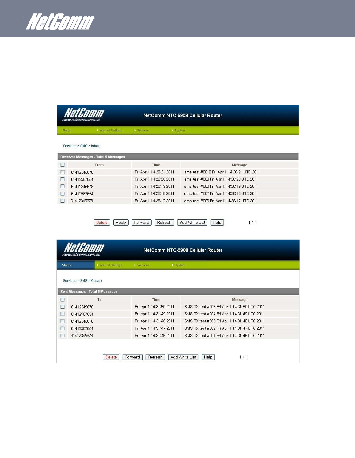
YML6908 NTC-6000 Series User Guide
www.netcommwireless.com
49
Inbox/Outbox
You can check all sent SMS messages in the SMS Outbox or you can read, delete, reply or forward an SMS message to another mobile device from the SMS Inbox.
You are also able to add the SMS message sender to the “White List” which is used to secure the Remote Diagnostics feature. Simply select the sender or recipient number and click the “Add
White List” button.
Figure66:Services‐SMS‐Inbox
Figure67:Services‐SMS‐Outbox
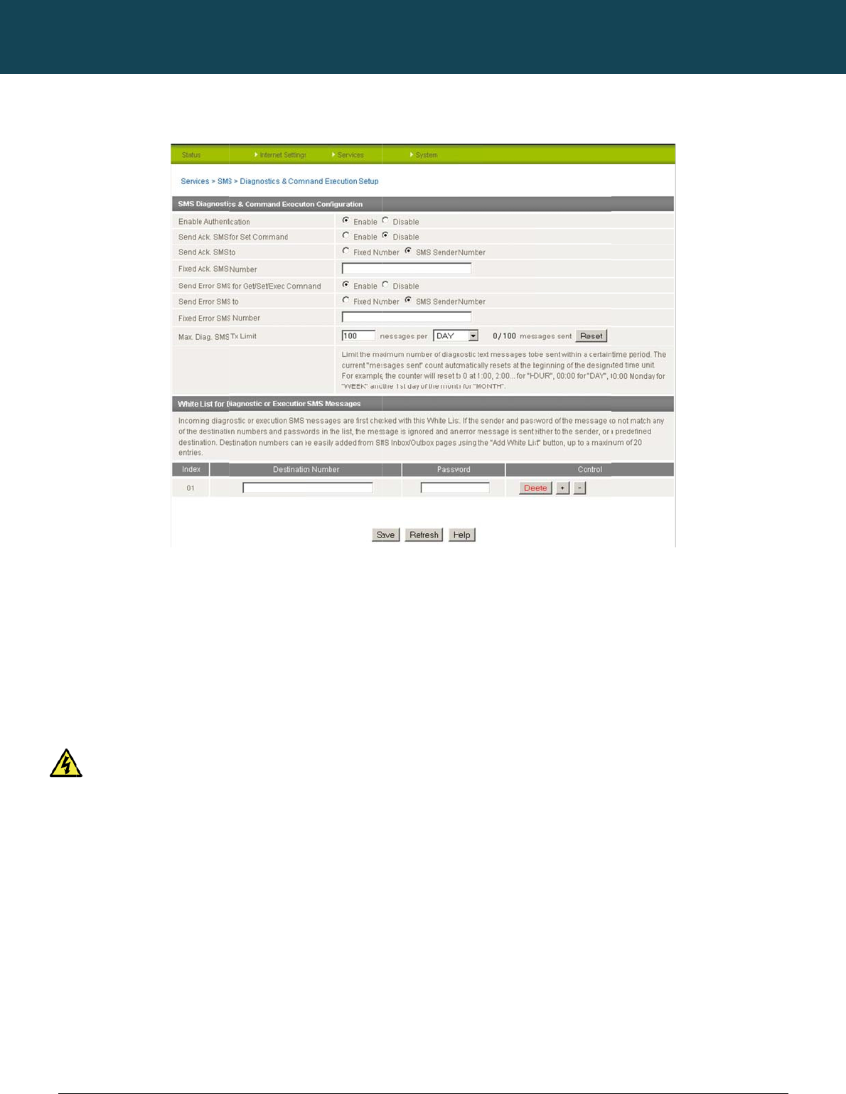
NT
C
50
ww
w
SM
En
a
Ena
b
If au
in th
If th
e
This
Se
n
Ena
b
If di
s
disa
Se
n
Sel
e
If “F
i
If th
e
C
-6000 Series – Indu
s
w
.netcommwireless.c
S Diagnostics
a
a
ble Authentic
a
b
le or disable checki
thentication is enabl
e
e “White List” for the
e
number does not e
x
is enabled by defau
It is highly reco
n
d Ack. SMS f
o
b
le or disable sendi
n
s
abled the router do
e
bled by default.
n
d Ack. SMS t
o
ct the destination to
xed Ack. SMS Num
b
e
SMS Sender Numb
s
trial M2M Wireless
R
c
om
a
nd Command
E
a
tion
ng the sender’s pho
n
e
d, the router will ch
e
corresponding sen
d
x
ist in “White List” or
lt.
mmended to enable
o
r Set Comma
n
n
g an acknowledge
m
e
s not send any ack
n
o
send an acknowled
g
b
er” is selected, the
a
b
er is selected, the a
c
R
outers
E
xecution Setu
p
n
e number against t
h
e
ck if the sender’s n
u
d
ing number. If they
m
the password does
security when utilisi
n
nd
m
essage after execu
t
n
owledgement after
e
g
ement message to
a
a
cknowledgement m
c
knowledgement me
s
p
Figure68:Servi
c
h
e allowed sende
r
“
W
u
mber exists in the “
W
m
atch, the Diagnosti
c
n
ot match, the route
r
n
g the Diagnostics/C
o
t
ion of a “Set” comm
a
e
xecution of a “Set”
c
a
fter the execution of
essage will be sent t
s
sage will be sent to
NETCOMM
c
es‐SMS–Diagnos
W
hite List” for incomi
n
W
hite List”. If it exist
s
c
s/Command is exe
c
r
does not execute t
h
ommand Execution
f
a
nd.
c
ommand. This can
b
f
a “Set” command.
t
o the predefined nu
m
sender directly. The
CALLDIRECT™
ticsandcommand
E
n
g Diagnostics/Com
m
s
, the router then che
c
uted.
h
e incoming Diagnos
t
f
eature.
b
e useful to determin
m
ber in the “Fixed A
c
default setting is to
u
SERIES – NT
C
E
xecutionSetup
m
and Execution SM
S
c
ks the password in
t
ics
/
Command Exec
u
e
if a command was
c
k. SMS Number” fiel
u
se “SMS Sender Nu
C
-6000 Serie
S
messages.
the incoming messa
u
tion SMS message.
received and execu
t
l
d.
u
mber”.
YML6908
s
ge against the pass
w
t
ed by the router. Thi
w
ord
s is

YM
L
ww
w
51
Fi
x
Ack
n
Se
n
Ena
b
If di
s
This
Se
n
Sel
e
If th
e
If t
The
Fi
x
The
M
a
You
hou
r
The
You
by
p
The
For
e
L
6908
w
.netcommwireless.c
x
ed Ack. SMS
N
n
owledgement mess
n
d Error SMS
f
b
le or disable the se
n
s
abled, the router do
function is disabled
n
d Error SMS t
o
ct the destination of
e
“Fixed Number” op
he “SMS Sender Nu
m
default setting is to
u
x
ed Error SMS
N
destination number
t
a
x. Diag. SMS
T
can set the maximu
m
r
/day/week or month
default is to send a
m
can check the curre
p
ressing the “Reset”
b
Total transmitted me
Please note: Ti
m
e
xample:
If the
If tim
e
If tim
e
If tim
e
c
om
N
umbe
r
ages sent after the e
f
or Get/Set/Exe
c
n
ding of an error me
s
es not send any err
o
by default.
o
the error messages
f
p
tion is selected, any
m
ber” option is sele
c
u
se “SMS Sender Nu
N
umbe
r
t
o which error mess
a
T
x Limit
m
number of ackno
w
basis.
m
aximum of 100 me
s
nt sent message co
u
b
utton.
e
ssage count resets
a
m
es displayed are in
time frame is set to “
e
frame is set to “DA
Y
e
period is set to “W
E
e
period is set to “M
O
xecution of a “Set” c
c
Comman
d
s
sage resulting from
o
r notifications after t
h
f
rom the execution o
f
error messages will
c
ted, any error mess
a
mber”.
a
ges from the executi
w
ledgement and erro
r
s
sages per day.
u
nt by looking next t
o
a
fter a reboot or at th
UTC (Coordinated
U
HOUR” and the curr
e
Y
” and current date
a
E
EK” and current dat
e
O
NTH” and current d
a
ommand will be sen
t
the execution of a G
h
e execution of a Ge
t
f
a Get/Set/Exec co
m
b
e sent to the prede
f
a
ges will be sent to t
h
on of a Get/Set/Exe
c
r
messages sent wh
e
the “Max. Diag. SM
S
e beginning of the ti
m
U
niversal Time) form
a
e
nt time is “04:30”, t
h
a
nd time is “04:30” 1
7
e
and time is “04:30”
a
te and time is “04:3
0
t
to this number.
et/Set/Exec comma
n
t
/Set/Exec comman
d
m
mand.
f
ined number in the
“
h
e sender directly.
c
command should b
e
n an SMS Diagnosti
c
S
Tx Limit” field. If th
e
m
e frame specified.
a
t.
h
en the counter will r
e
7
th of March, then th
e
”
Saturday, then the
c
0” 17th of March, th
e
n
d.
.
“
Fixed Error SMS Nu
m
e sent.
c
s and/or Command
e
maximum number
h
e
set to zero at “05:0
0
e
counter will reset t
o
c
ounter will reset to z
e
n the counter will re
s
m
ber” field.
is executed. You ca
n
h
as been exceeded,
0
”.
o
zero at “00:00” 18t
h
e
ro at “00:00” on the
s
et to zero at “00:00”
NTC-6000 Series
U
n
set the maximum li
you can also reset t
h
of March.
e
coming Monday.
”
1st of April.
U
ser Guide
m
it on a per
h
e sent message co
u
u
nter

NTC-6000 Series – Industrial M2M Wireless Routers YML6908
52
www.netcommwireless.com
NETCOMM CALLDIRECT™ SERIES – NTC-6000 Series
White List
A maximum number of 20 entries can be stored in the router.
If Authentication is enabled, any incoming Diagnostics/Command Execution SMS messages are processed only if the sender’s number exists in White List and the message password matches
with the password specified in the White List.
One blank entry is shown by default and you can add or delete an entry by pressing the “+” or “–“ button. The White List numbers and passwords can be cleared by pressing the “Delete” button.
To add an entry, simply enter the appropriate phone number and password and click “Save”.
Message Storage for Diagnostic Messages
Diagnostic messages (Diagnostic commands, acknowledgements and error notification messages) sent to remote destination are stored in Inbox/Outbox.
Security
In order to provide security for SMS command execution, it is recommended that all SMS commands be subject to successful authentication against the White List as well as setting a password
for each phone number entered.
This prevents unauthorized or accidental execution of SMS commands.

YML6908 NTC-6000 Series User Guide
www.netcommwireless.com
53
SMS Command format
Generic Format for reading variables:
get VARIABLENAME
PASSWORD get VARIABLENAME
Generic Format for writing to variables:
set VARIABLENAME=VALUE
PASSWORD set VARIABLENAME=VALUE
Generic Format for executing a command:
execute COMMAND
PASSWORD execute COMMAND
Replies
Upon receipt of successfully formatted, authenticated (if required) command, the router will reply to the SMS in the following format:
TYPE SMS CONTENTS NOTES
Get Command “VARIABLENAME=VALUE”
Set Command “Successfully set VARIABLENAME to VALUE”. Only sent if the acknowledgment message function is enabled
Execute Command“Successfully executed command”
Table11:SMSCommandReplies
Where “VARIABLENAME” is the name of the value to be read
Where “VARIABLENAME(x)” is the name of another value to be read
Where “VALUE” is the content to be written to the “VARIABLENAME”
Where “COMMAND” is a supported command to be executed by the device (e.g. reboot)
Where “PASSWORD” is the password (if configured) for the corresponding sender number specified in the White List.
Multiple commands can be sent in the same message, if separated by a semicolon.
For Example:
i. get VARIABLENAME1; get VARIABLENAME2; get VARIABLENAME3
ii. PASSWORD get VARIABLENAME1; get VARIABLENAME2
iii. set VARIABLENAME=VALUE1 ; set VARIABLENAME2=VALUE2
iv. PASSWORD set VARIABLENAME1=VALUE1; set VARIABLENAME2=VALUE2; set VARIABLENAME3=VALUE3
If required, values can also be bound by an apostrophe, double apostrophe or back tick.
For Example:
v. “set VARIABLE=’VALUE’”
vi. “set VARIABLE=”VALUE””
vii. “set VARIABLE=`VALUE`”
viii. “get VARIABLE”
A password (if required), only needs to be specified once per SMS, but can be prefixed to each command if desired.
ix. “PASSWORD get Variable1”; “get VARABLE2”
x. “PASSWORD set VARIABLE1=VALUE1”; “set VARIABLE2=VALUE2”

NTC-6000 Series – Industrial M2M Wireless Routers YML6908
54
www.netcommwireless.com
NETCOMM CALLDIRECT™ SERIES – NTC-6000 Series
If the command sent includes the “reboot” command and has already passed the White List password check, the device keeps this password and executes the remaining
command line after the reboot with this same password.
For Example:
xi. “PASSWORD execute reboot; get Variable1”; “get VARABLE2”
xii. “PASSWORD execute reboot; PASSWORD get Variable1”; “get VARABLE2”
Commands are case insensitive; however variable names and values are case sensitive.
List of Valid Commands (which can be used in conjunction with the execute command)
“pdpcycle”, “pdpdown” and “pdpup” commands can have a profile number suffix ‘x’ added. Without the suffix specified, the command operates against the current active profile or last active
profile.
# COMMAND NAME DESCRIPTION
1 reboot Immediately perform a soft reboot
2 pdpcycle or pdpcyclex
Disconnect (if connected) and reconnect the 3G connection. If a profile number is selected in the command, try
to disconnect/reconnect the specified profile in case the profile is active. If no profile number is selected, try to
disconnect/reconnect the current active profile. This command can report an error if no profile number is
selected and there is no currently activated profile.
3 pdpdown or pdpdownx
Disconnect the PDP. If a profile number is selected in the command, try to disconnect the specified profile in case
the profile is active. If no profile number is selected, try to disconnect the current active profile. Reports an error if
no profile number is selected and there is no currently activated profile.
4 pdpup or pdpupx
Reconnect the PDP. If a profile number is selected in the command, try to connect with the specified profile. If no
profile number is selected, try to connect to the last active profile. The router will check the currently activated
profile and disconnect this profile before executing the command. Reports an error if no profile number is selected
and there is no stored last active profile number.
Table12:ListofValidSMSCommands

YML6908 NTC-6000 Series User Guide
www.netcommwireless.com
55
List of Valid Variables:
Where “x” is a profile number (1-6). If no profile is specified, variables are read for or written to for the current active profile. If a profile is specified, the variable is read for or written to for the
specified profile number (‘x’).
# RDB VARIABLE NAME SMS VARIABLE
NAME READ/WRITE DESCRIPTION EXAMPLE
0
link.profile.x.enable
link.profile.x.apn
link.profile.x.user
link.profile.x.pass
link.profile.x.auth_type
link.profile.x.iplocal
link.profile.x.status
profile
or
profilex
RW
Profile
Read:
(profile no,apn,user,pass,auth,iplocal,status)
1,Telstra.internet,username,password, chap,202.44.185.111,up
Write:
(apn, user, pass,auth)
Telstra.internet,username,password
1 link.profile.x.apn apn or apnx RW APN telstra.internet
2 link.profile.x.user username or usernamex RW 3G username Guest, could also return “null”
3 link.profile.x.pass
password or password RW 3G password Guest, could also return “null”
4 link.profile.x.auth_type
authtype or authtypex RW 3G Authentication type ”pap” or”chap”
5 link.profile.x.iplocal wanip or wanipx R WAN IP address 202.44.185.111
6 wwan.0.radio.information.signal_str
ength
rssi R 3G signal strength 65 dBm
7 wwan.0.imei imei R IMEI number 359102128941027512
8 statistics.usage_current
usage R 3G data usage of current
session
“Rx 500 bytes, Tx 1024 bytes, Total 1524 bytes” or “Rx 0
byte, Tx 0 byte, Total 0 byte” when wwan down
9 statistics.usage_current
wanuptime R Up time of current 3G session 1 days 02:30:12 or 0 days 00:00:00 when wwan down
10 /proc/uptime deviceuptime R Device up time 1 days 02:30:12
11 wwan.0.system_network_status.cur
rent_band
band R Current 3G frequency WCDMA 850
Table13:SMS‐ValidVariables

NTC-6000 Series – Industrial M2M Wireless Routers YML6908
56
www.netcommwireless.com
NETCOMM CALLDIRECT™ SERIES – NTC-6000 Series
SMS Diagnostics Examples
The examples below demonstrate various combinations of supported commands. This is not a complete list. To obtain a complete list, please contact NetComm.
DESCRIPTION AUTHENTICATION INPUT EXAMPLE
Send SMS to change APN
Not Required
set apn1=Telstra.internet
set apn2=”3netaccecss”
Required Password1234 set apn1=Telstra.internet
Password1234 set apn2=3netaccecss
Send SMS to change the 3G username
Not Required set username=’NetComm’
Required Password1234 set username= ”NetComm”
Send SMS to change the 3G password Not required set password= `NetComm`
Required Password1234 set password= `NetComm`
Send SMS to change the 3G
authentication
Not required set authtype= ‘pap’
Required Password1234 set authtype = pap
Send SMS to reboot Not Required execute reboot
Required Password1234 execute reboot
Send SMS to check the WAN IPaddressNot Required get wanip
Required Password1234 get wanip
Send SMS to check the 3G signal strength Not Required get rssi
Required Password1234 get rssi
Send SMS to check the IMEI number Not Required get imei
Required Password1234 get imei
Send SMS to check the current band Not Required get band
Required Password1234 get band
Send SMS to Disconnect (if disconnected)
and reconnect the 3G connection
Not Required execute pdpcycle
Required Password1234 execute “pdpcycle1”
Send SMS to disconnect the 3G
connection
Not Required execute pdpdown1
Required Password1234 execute “pdpdown1”
Send SMS to connect the 3G connection Not Required execute pdpup
Required Password1234 execute pdpup1
Send multiple get command Not Required get wanip; get rssi
Required Password1234 get wanip; get rssi
Send multiple set command Not Required set apn1=”3netaccecss”; set password1=’NetComm’
Required Password1234 set apn=”3netaccecss”; set password=NetComm
Table14:SMSDiagnosticsCommandExamples
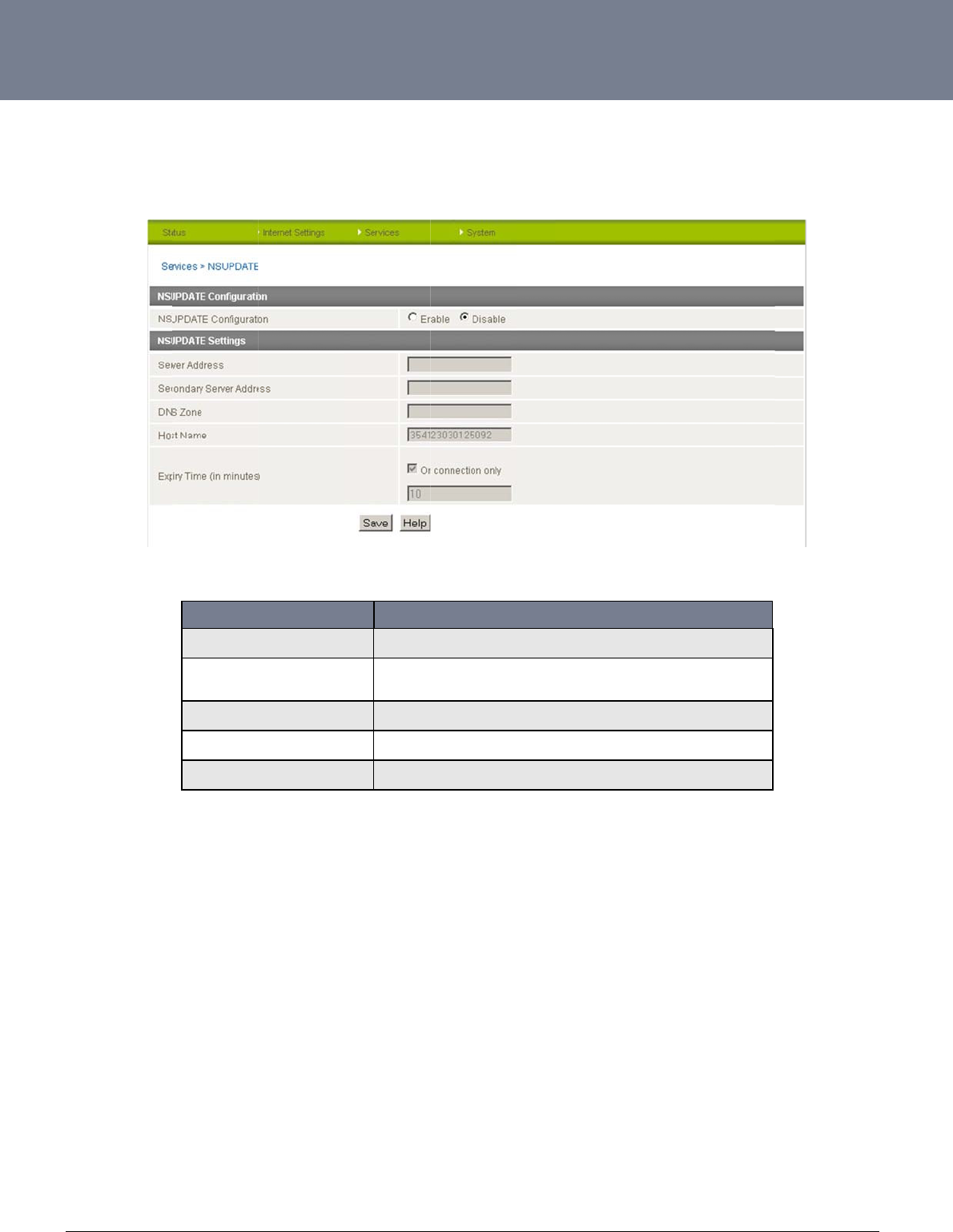
YM
L
ww
w
57
N
S
NS
U
L
6908
w
.netcommwireless.c
S
Update
U
pdate is used to up
c
om
date an internal DN
S
Server Address
Secondary Server A
d
DNS Zone
Host Name
Expiry Time (in minu
t
S
resource. This can
b
FIELD
d
dress
t
es)
b
e used to enable a
f
The server ad
d
The secondar
y
Specify the D
N
Specifies the
c
The newly-ad
d
Table1
5
fully qualified domai
n
Figure69:Se
r
d
ress is the name server t
o
y
server address is a back
u
N
S domain to be updated.
c
hanges to be made to on
e
d
ed records’ time to live.
5
:Services–NSUp
d
n
name (FQDN) to b
e
r
vices‐NSUpdate
DESCRIPTIO
N
o
which updates will be se
n
u
p name server to which u
e
or more DNS records.
d
ate
e
used to access the
N
n
t to.
p
dates will be sent to.
NTC-6000 Series
U
e
route
r
.
U
ser Guide
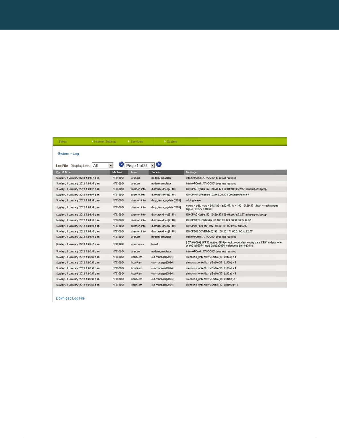
NT
C
58
ww
w
S
Vi
e
This
The
Sel
e
C
-6000 Series – Indu
s
w
.netcommwireless.c
S
yste
m
e
wing the
s
facility is available
b
System Log enables
cting the appropriat
e
s
trial M2M Wireless
R
c
om
m
Fe
a
s
ystem lo
g
b
y clicking on the “S
y
s
you to troubleshoot
e
logging level will s
h
R
outers
a
ture
s
g
y
stem” menu followe
d
any issues you may
h
ow you either infor
m
s
d
by “Log“.
be experiencing wit
h
ational messages a
b
NETCOMM
h
your router.
b
out your router o
r
e
v
CALLDIRECT™
Figure70:Syste
m
v
ery message produ
c
SERIES – NT
C
m
LogPage
c
ed when “All” is sel
e
C
-6000 Serie
e
cted.
YML6908
s
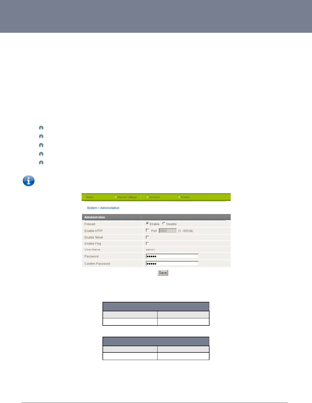
YM
L
ww
w
59
R
e
This
Onc
feat
u
To
g
con
n
To
c
The
The
1.
2.
L
6908
w
.netcommwireless.c
e
mote Ad
m
facility is available
b
e Remote administr
a
u
res.
g
et remote access, y
o
n
ection has been est
onfigure Remote Ad
m
Click
Chan
g
If you
You
m
Click
Note: The
p
WAN IP address bel
steps below illustrat
e
Open a new brow
In the address ba
r
c
om
m
inistration
b
y clicking on the “S
y
a
tion is enabled, you
o
u have to connect t
o
ablished.
m
inistration follow th
e
“Enable HTTP” to ac
g
e the Remote Admi
wish to use Telnet o
m
ay change the rem
o
“Save”
p
assword will only be
ow is an example on
e
how to access the
r
ser window (e.g. Int
e
r, enter the router’s
W
y
stem” menu followe
d
are able to access t
h
o
the WAN IP addre
s
e
steps below:
tivate Remote Admi
n
nistration Port numb
e
r ping the router sel
e
o
te access password
changed if you ent
e
ly, yours will be diffe
r
outer’s configuratio
n
e
rnet Explorer, Firefo
x
W
AN IP address and
d
by “Administration”
h
e router’s web-base
s of the router on th
e
n
istration
e
r if required; the fac
e
ct these options.
for enhanced secur
e
r two matching pass
rent.
h
Username
Password
h
Username
Password
n
page remotely (fro
m
x
, Safari ...).
assigned port numb
.
e
d configuration pag
e
e
port assigned in th
e
c
tory default is 8080.
r
ity.
s
words. It is not nece
s
Figu
r
h
ttp://10.10.0.10:80
h
ttp://10.10.0.10:80
m
a remote compute
r
er, e.g. “10.10.10.10
e
s from a remote loc
a
e
configuration page
s
sary to change the
r
e71:System–
A
d
m
80
admin
admin
Table16:Remote
A
90
root
admin
Table17:Rem
o
r
):
: 8080”.
a
tion to make config
u
(e.g. 8080) after a c
o
p
assword if you are
o
m
inistration
A
dminLoginDetail
s
o
teRootLoginDet
a
NTC-6000 Series
U
u
ration changes and
o
nnection to the cell
u
o
nly changing the in
c
s
a
ils
U
ser Guide
to enable or disable
u
lar network via a da
t
c
oming port number
.
t
a
.
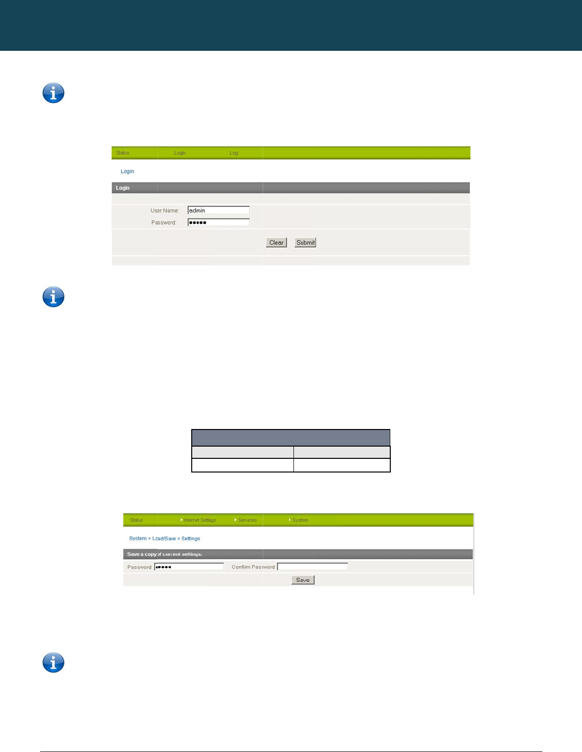
NT
C
60
ww
w
3.
Sa
v
This
To s
To l
o
Key
This
C
-6000 Series – Indu
s
w
.netcommwireless.c
Note: Yo
u
Click “Login” and
Note:
T
user.
v
ing a Copy of t
facility is available
b
ave a copy of the ro
u
o
gin to the router in r
o
in the root manager
will download a cop
y
It is NOT p
o
the name o
s
trial M2M Wireless
R
c
om
u
can find the router’
s
type “admin” or “ro
o
T
o perform functions
he Router’s Co
n
b
y clicking on the “S
y
u
ter configuration se
t
o
ot manager mode,
p
Password of “admin
”
y of the current setti
n
o
ssible to edit the co
n
f the file if you wish
b
R
outers
s
WAN IP address b
y
o
t” in the Username
a
like Firmware upgra
d
n
figuration
y
stem” menu followe
d
t
tings you need to lo
g
p
lease use the follo
w
”
and click Save.
n
gs from the router t
o
n
tents of the file dow
b
ut the filename exte
n
y
clicking on the “Sta
t
nd “admin” in the P
a
d
e, device configura
t
d
by “Load / Save” a
n
g
in in the root mana
g
w
ing login details:
Username
Password
o
your PC.
nloaded; if you modi
f
n
sion must remain “.
c
NETCOMM
tus” menu. The Loc
a
a
ssword fields (witho
u
F
t
ion backup and to r
e
n
d then the “Settings
g
er mode.
http://192.168.20.
1
Figure73:Sys
t
fy the contents of th
e
c
fg.tar.gz”
CALLDIRECT™
a
l field in the WWAN
s
u
t quotes). Then clic
k
F
igure72:LoginScr
e
e
store and reset the
” menu item on the r
i
1
root
admin
t
em‐Load/Save–
S
e
configuration file in
SERIES – NT
C
s
ection shows the ro
u
k
on the “Submit” bu
t
e
en
r
outer to factory def
a
ght.
S
ettings
any way you will not
C
-6000 Serie
uter’s WAN IP addre
s
t
ton.
a
ults, you need to be
be able to restore it
YML6908
s
s
s.
logged in
as the roo
later. You may chan
g
t
g
e
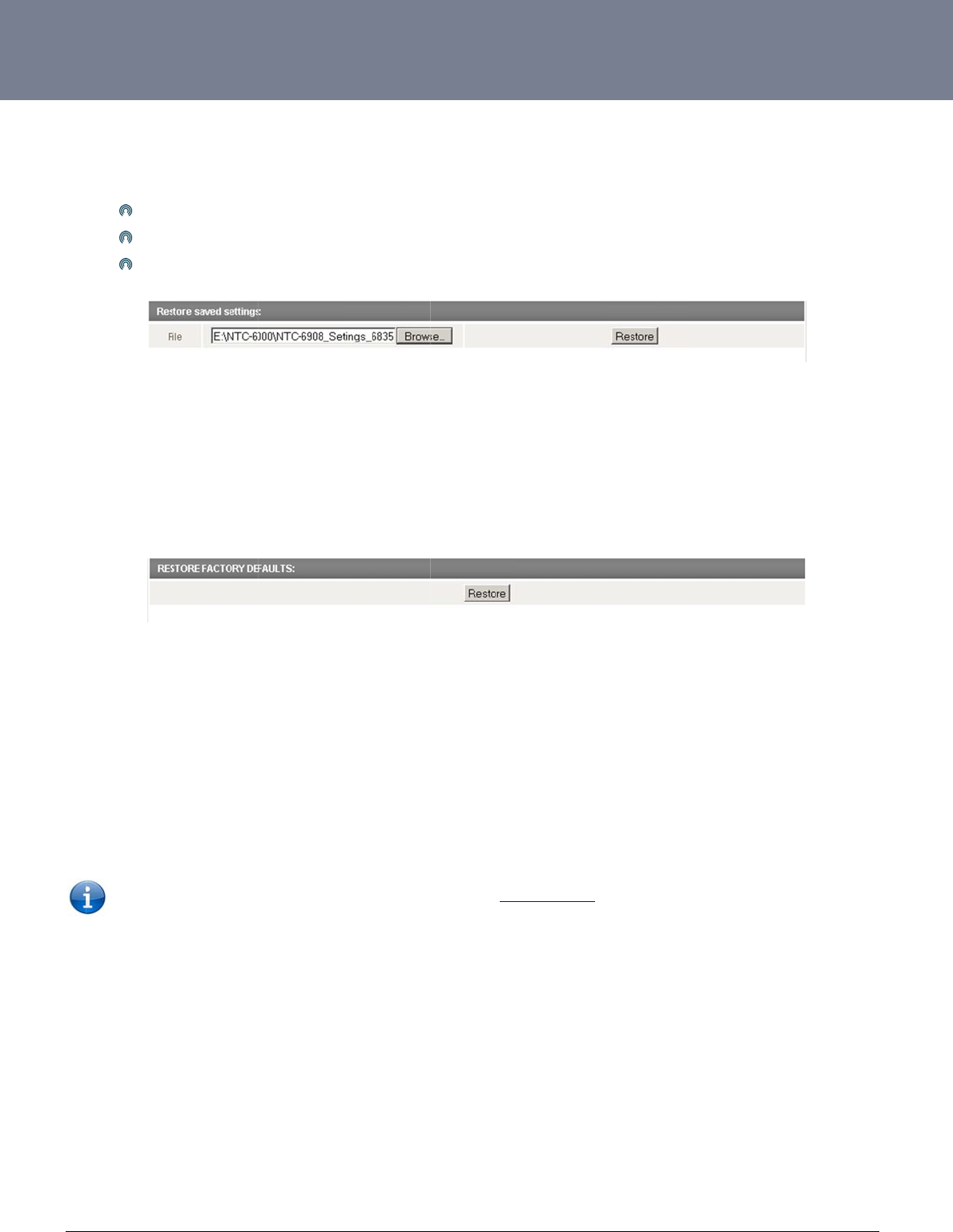
YM
L
ww
w
61
R
e
This
R
e
This
Clic
k
U
p
This
The
L
6908
w
.netcommwireless.c
e
sto
r
ing a
C
facility is available
b
Click
Selec
Click
e
sto
r
ing th
e
facility is available
b
k
Restore to restore t
p
grading t
h
facility is available
b
firmware of the rout
e
Note: In order t
o
c
om
C
opy of th
e
b
y clicking on the “S
y
Browse.
t the configuration fil
Restore.
e
Routers
C
b
y clicking on the “S
y
he factory default c
o
h
e Router’
s
b
y clicking on the “S
y
e
r can be updated lo
c
o
perform an update
,
e
Router’s
y
stem” menu followe
d
e you wish to restor
e
C
onfigurat
y
stem” menu followe
d
o
nfiguration settings.
s
System
o
y
stem” menu followe
d
c
ally via LAN conne
c
,
you must be logge
d
Configura
t
d
by “Load / Save” a
n
.
Figure74:Resto
r
ion to the
F
d
by “Load / Save” a
n
Figure75:Resto
r
o
r Recover
y
d
by “Load / Save” o
p
c
tion and also via re
m
d
into the router as th
tion
n
d then the “Settings
r
ingaCopyofthe
R
F
actory D
e
n
d then the “Settings
r
ingtheRouterCo
n
r
y Console
p
tion and then the “
U
m
ote access. Both u
p
e root user (see Re
m
” menu item on the r
i
R
outer'sConfigurat
i
e
faults
” menu item on the r
i
n
figurationtoFacto
Software
V
U
pload” option on th
e
p
grade types follow
a
m
ote Administration f
o
ght.
i
on
ght.
r
yDefaultSettings
V
ersion
right.
simila
r
process.
o
r more details).
NTC-6000 Series
U
U
ser Guide
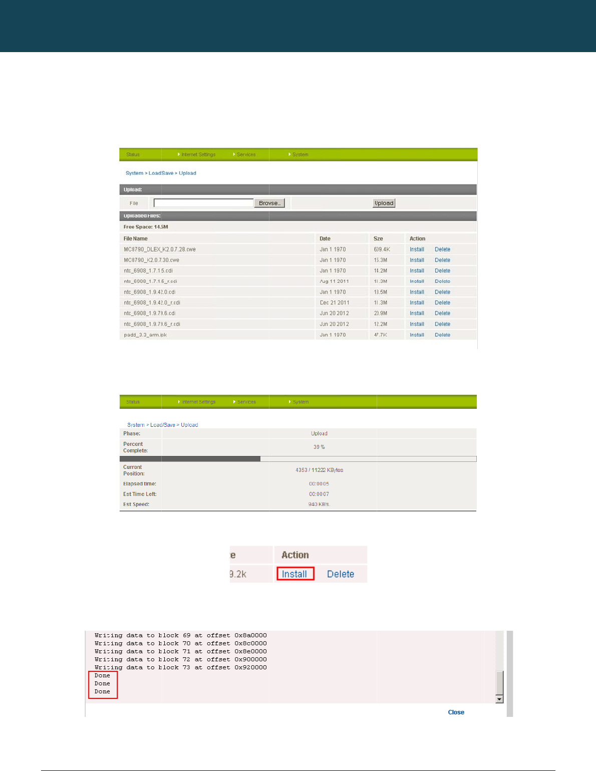
NT
C
62
ww
w
L
o
The
You
Onc
the
s
Wh
e
Onc
Pre
s
the
s
C
-6000 Series – Indu
s
w
.netcommwireless.c
o
cal Firmw
a
firmware update pro
can do this by clicki
n
e you have selected
s
tatus bar reaches 1
0
e
n the upload has co
m
e you see “Done” sh
s
s and hold the reset
s
ystem recovery mo
d
s
trial M2M Wireless
R
c
om
a
re Upgra
d
cess has two steps.
n
g on the browse bu
the system recover
y
0
0% and the “Phase
:
m
pleted, the screen
own as per the scre
e
button for approxim
a
d
e.
R
outers
d
e
The first step is to u
p
tton and then to navi
y
image file to use, cl
i
:
” has changed to C
o
should refresh and li
e
nshot below, you c
a
a
tely 5 – 10 seconds
p
load and install the
s
gate to where the re
c
Figure76:Syste
m
ck Upload to uploa
d
o
mplete.
Figure77:Syste
m
st the system recov
e
Figure78:Firm
w
a
n then boot into the
s
Figure79:Firm
w
until the LEDs on th
e
NETCOMM
s
ystem recovery ima
c
overy image upgra
d
m
‐Load/Save‐Up
l
d
the file. You will the
n
m
‐Load/Save‐Fir
m
e
ry file you have just
u
w
areInstallLin
k
s
ystem recovery mo
d
w
areUpgradeDone
e
front of the router s
t
CALLDIRECT™
g
e onto the router.
d
e file is located on
y
l
oad
n
see a progress ba
r
m
wareUpgradePr
o
u
ploaded. Click on t
h
d
e to install the main
Message
t
art to flash in an ON
SERIES – NT
C
y
our computer.
r
as shown in the scr
e
o
cess
h
e “Install” link to the
system software.
/ OFF sequence an
d
C
-6000 Serie
e
enshot below. The
u
right of this.
d
then release it. The
YML6908
s
u
pload has finished
w
router will now boot
w
hen
into
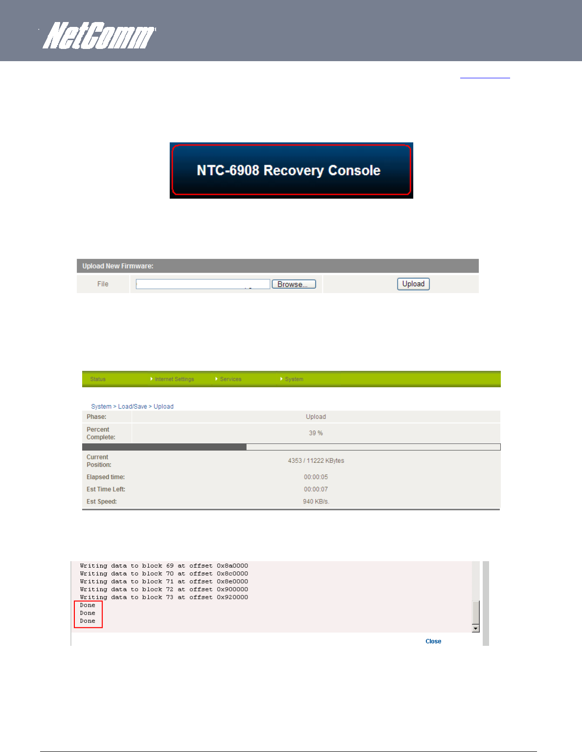
YML6908 NTC-6000 Series User Guide
www.netcommwireless.com
63
The second step is to upload and install the main system software image. To do this, open your web browser (e.g. Internet Explorer/Firefox/Safari) and navigate to http://192.168.20.1/
Click “Login” and type “root” in the Username and “admin” in the Password fields (without quotes). Then click on “Submit”.
The banner at the top of the page should now be different to show that the router is currently in recovery console mode.
Figure80:NTC‐6908RecoveryConsoleBanner
To upload the main system software, click on “Application Installer” from the menu at the top of the page and then click on the browse button and navigate to where the main system image
upgrade file is located on your computer.
Once you have selected the recovery image file to use, click Upload to upload the file. You will then see a progress bar as shown in the screenshot below. The upload has finished when the
status bar reaches 100% and the “Phase:” has changed to Complete
.
When the upload has completed, the screen should refresh and list the file you have just uploaded. Click on the “Install” link to the right of this.
Once you see “Done” shown as per the screenshot below, click on “Reboot” at the top of the page and then click the “Reboot” button to restart the router
Figure81:System‐ Load/Save‐ UploadFirmware
Figure82:UploadingMainFirmwareImage
Figure85:MainFirmwareImage‐ DoneMessage
Figure84:RecoveryConsole‐FirmwareUploadingExample
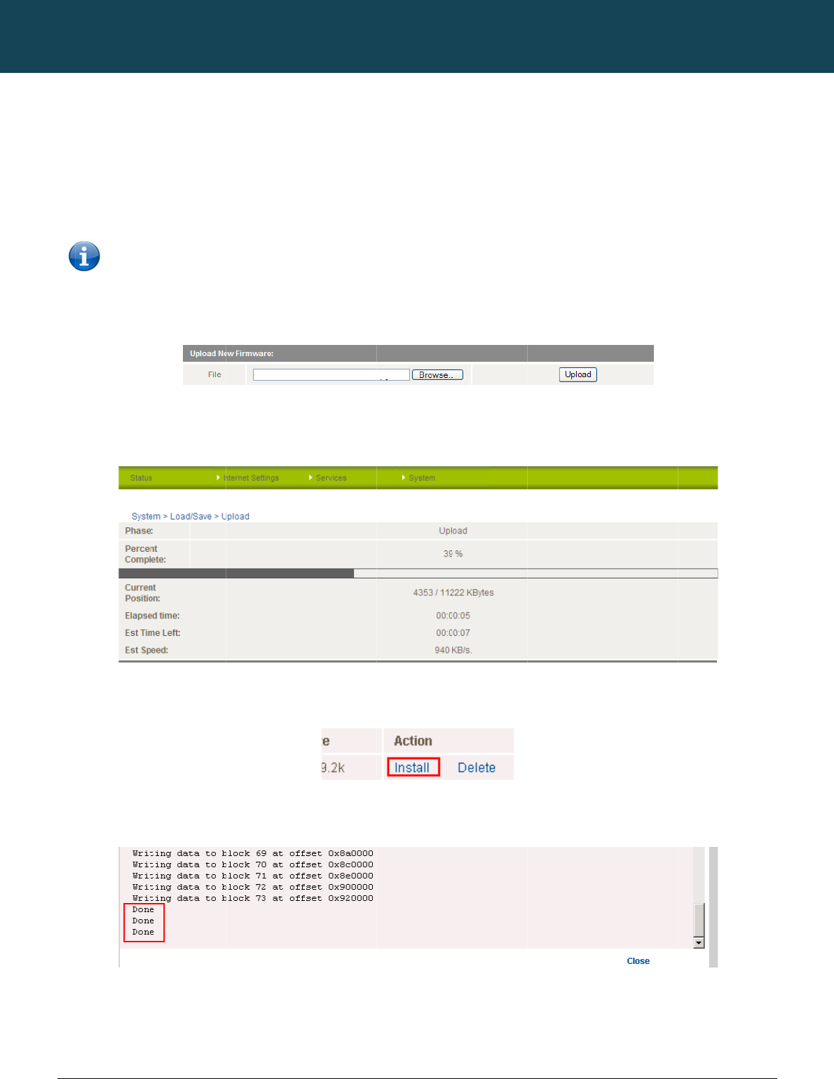
NT
C
64
ww
w
R
e
The
1.
2.
The
file i
s
Onc
stat
u
Wh
e
Onc
The
com
C
-6000 Series – Indu
s
w
.netcommwireless.c
e
mote Fir
m
remote firmware up
d
Upload and instal
l
Upload and instal
l
Note: Do
performe
d
first step is to uploa
d
s
located on your co
m
e you have selected
u
s bar reaches 100
%
e
n the upload has co
m
e you see “Done” sh
second step is to up
pute
r
s
trial M2M Wireless
R
c
om
m
ware Upg
d
ate process has tw
o
l the system recover
y
l the main system im
a
not interrupt the po
w
d
.
d
and install the syst
e
m
pute
r
.
the recovery image
f
%
and the “Phase:” h
a
m
pleted, the screen
own as per the scre
e
p
load and install the
m
R
outers
rade
o
steps:
y
image to the route
r
a
ge to the router.
w
er during a remote f
i
e
m recovery image
o
f
ile to use, click “Upl
o
a
s changed to Comp
should refresh and li
e
nshot below,
m
ain system softwar
e
.
rmware upgrade, as
nto the router. You c
Figure86:Syste
m
o
ad” to upload the fil
lete.
Figure87:Uplo
a
st the file you have j
u
Figure
8
Figure89:Firm
w
e
image. Click on the
NETCOMM
s
this may render the
an do this by clickin
g
m
‐Load/Save‐Up
l
l
e. You will then see
a
a
dingFirmwareFile
u
st uploaded. Click
o
8
8:FirmwareInstal
l
w
areUpgradeDone
browse button agai
n
CALLDIRECT™
router unable to sta
r
g
on the b
r
owse butt
o
l
oadFirmware
a
progress bar as sh
o
n the “Install” link to
l
Lin
k
Message
n
and navigate to wh
SERIES – NT
C
t
up and will require
a
o
n and then to navig
a
own in the screensh
o
the right of this.
e
re the main system
C
-6000 Serie
a local system reco
v
ating to where the r
e
ot below. The uploa
d
image upgrade file i
YML6908
s
v
ery upload to be
covery image upgra
d
d
has finished when t
s located on your
d
e
he
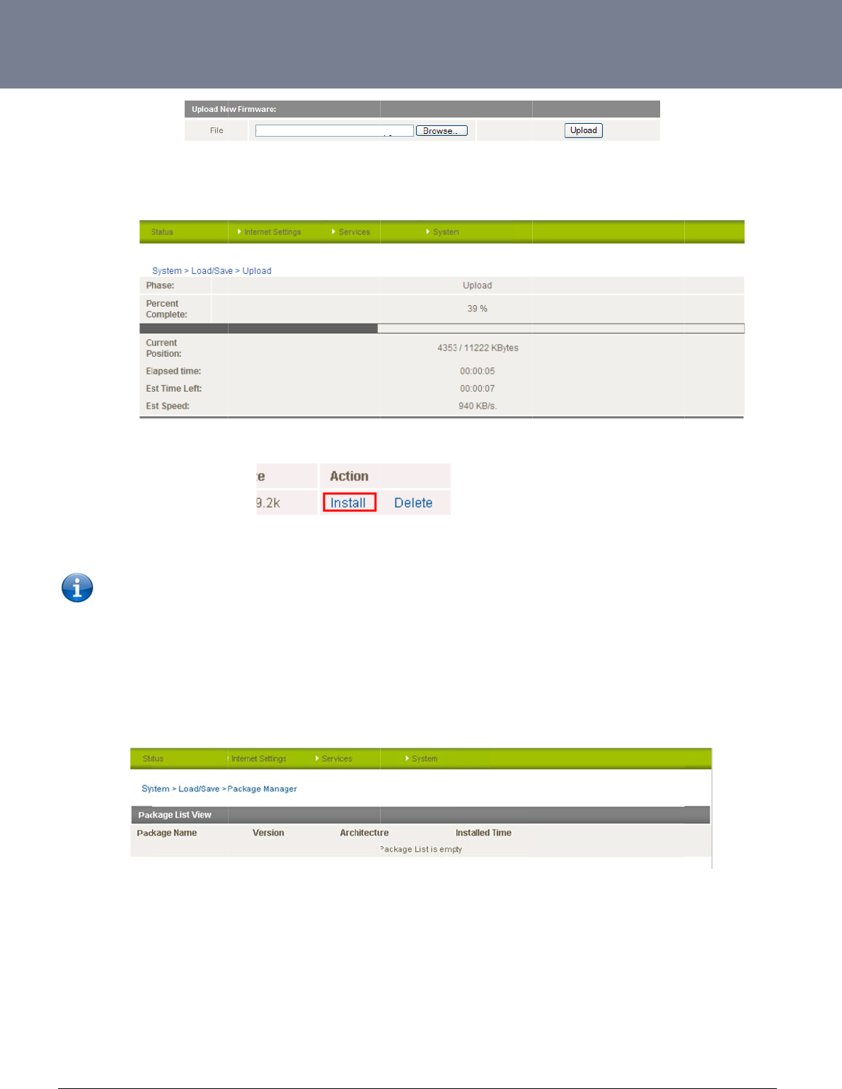
YM
L
ww
w
65
Onc
stat
u
Wh
e
Onc
P
a
The
L
6908
w
.netcommwireless.c
e you have selected
u
s bar reaches 100
%
e
n the upload has co
m
e the install has com
Note: This proc
e
a
ckage M
a
package manager p
c
om
the main system im
a
%
and the “Phase:” h
a
m
pleted, the screen
pleted, the router wil
e
ss can take up to 1
0
a
nage
r
p
age lists additional
s
a
ge file to use, click
U
a
s changed to Comp
should refresh and li
l automatically rebo
o
0
minutes.
s
oftware that has be
e
Figure90:Syste
m
U
pload to upload the
lete.
st the file you have j
u
o
t, install the new ma
i
e
n installed to the rou
Figure91:Syste
m
m
‐Load/Save‐Up
l
e
file. You will then se
u
st uploaded. Click
o
in system image an
d
u
te
r
offering extra fun
m
‐Load/Save‐Pa
c
l
oadFirmware
e a progress bar as
s
o
n the “Install” link to
d
then start up and r
e
ctionality to the rout
e
c
kageManage
r
s
hown in the screen
s
the right of this.
connect to your sele
c
r.
NTC-6000 Series
U
s
hot below. The uplo
e
cted Internet servic
e
U
ser Guide
ad has finished whe
n
e
.
n
the
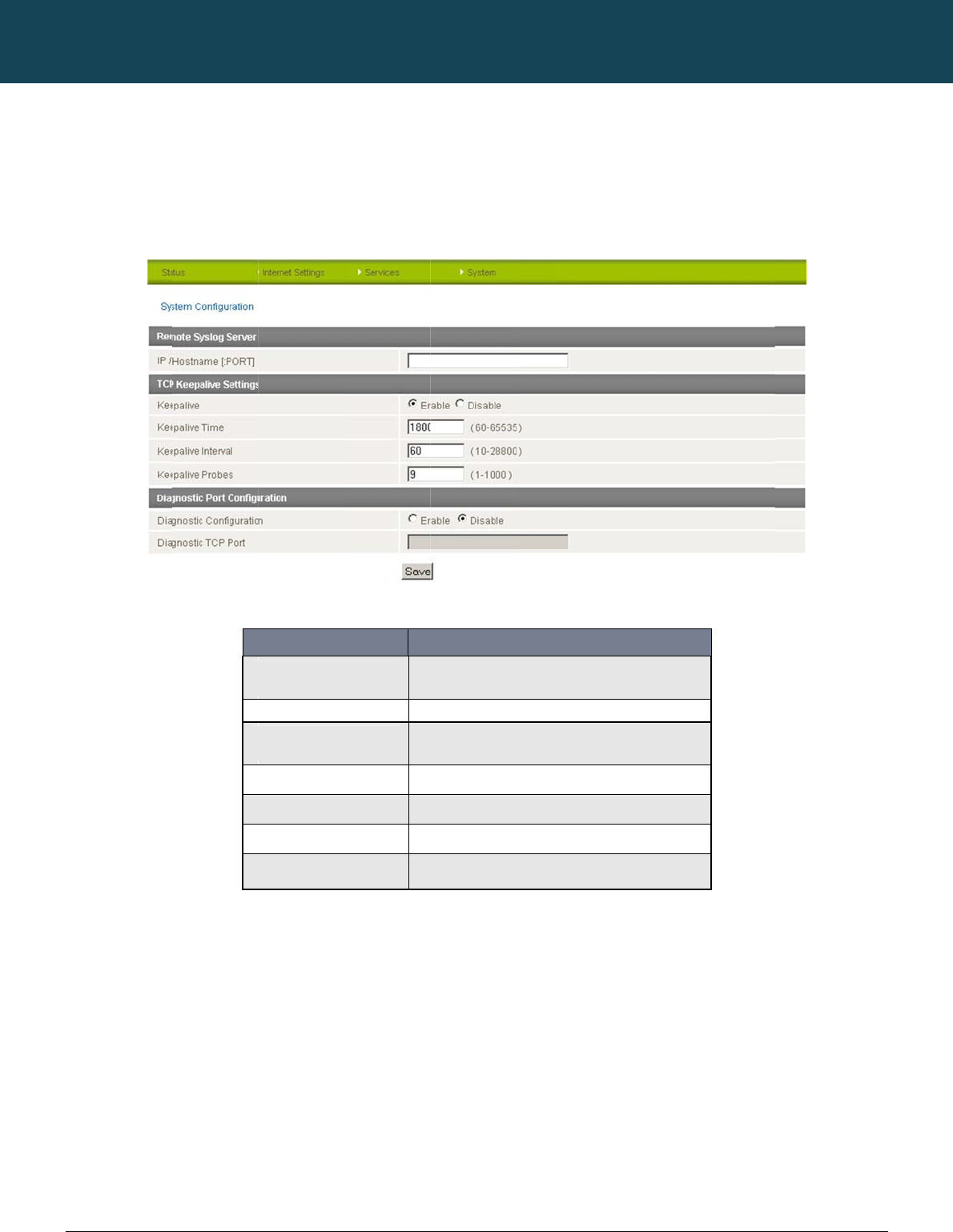
NT
C
66
ww
w
S
y
The
TCP
con
f
C
-6000 Series – Indu
s
w
.netcommwireless.c
y
stem Con
f
System configuratio
n
Keepalive can be u
s
f
irm the network con
n
s
trial M2M Wireless
R
c
om
f
iguration
n
page is used to sp
e
s
ed to ensure the W
W
n
ection is still valid.
IP
K
e
K
e
K
e
K
e
Di
Di
R
outers
e
cify an external sysl
W
AN connection do
e
OPTION
/ Hostname [:PORT]
e
epalive
e
epalive Time
e
epalive Interval
e
epalive Probes
agnostic Configuration
agnostic TCP Port
og server and the T
C
s not become disco
n
Figure93:Syste
m
The
info
r
Sel
e
The
sen
t
The
The
Table18:Syste
m
NETCOMM
C
P Keepalive setting
s
n
nect due to inactivit
m
ConfigurationPa
g
IP address and port of th
e
rmation sent to.
e
ct to enable or disable th
e
interval between the last
p
t
.
time between subsequen
t
number of TCP Keepalive
Select this optio
n
Enter the port num
b
m
ConfigurationSet
t
CALLDIRECT™
s
.
y
by periodically sen
g
e
DEFINITION
e
external syslog server yo
u
e
TCP Keepalive function.
p
acket sent and the first T
C
t
TCP Keepalive packets.
packets to send.
n
to enable diagnostic con
b
er you wish the diagnosti
c
t
ings
SERIES – NT
C
ding a ping request
u
would like logging
C
P keepalive packet being
f
iguration mode.
information sent to.
C
-6000 Serie
message to a WAN
I
YML6908
s
P address or domai
n
n
to
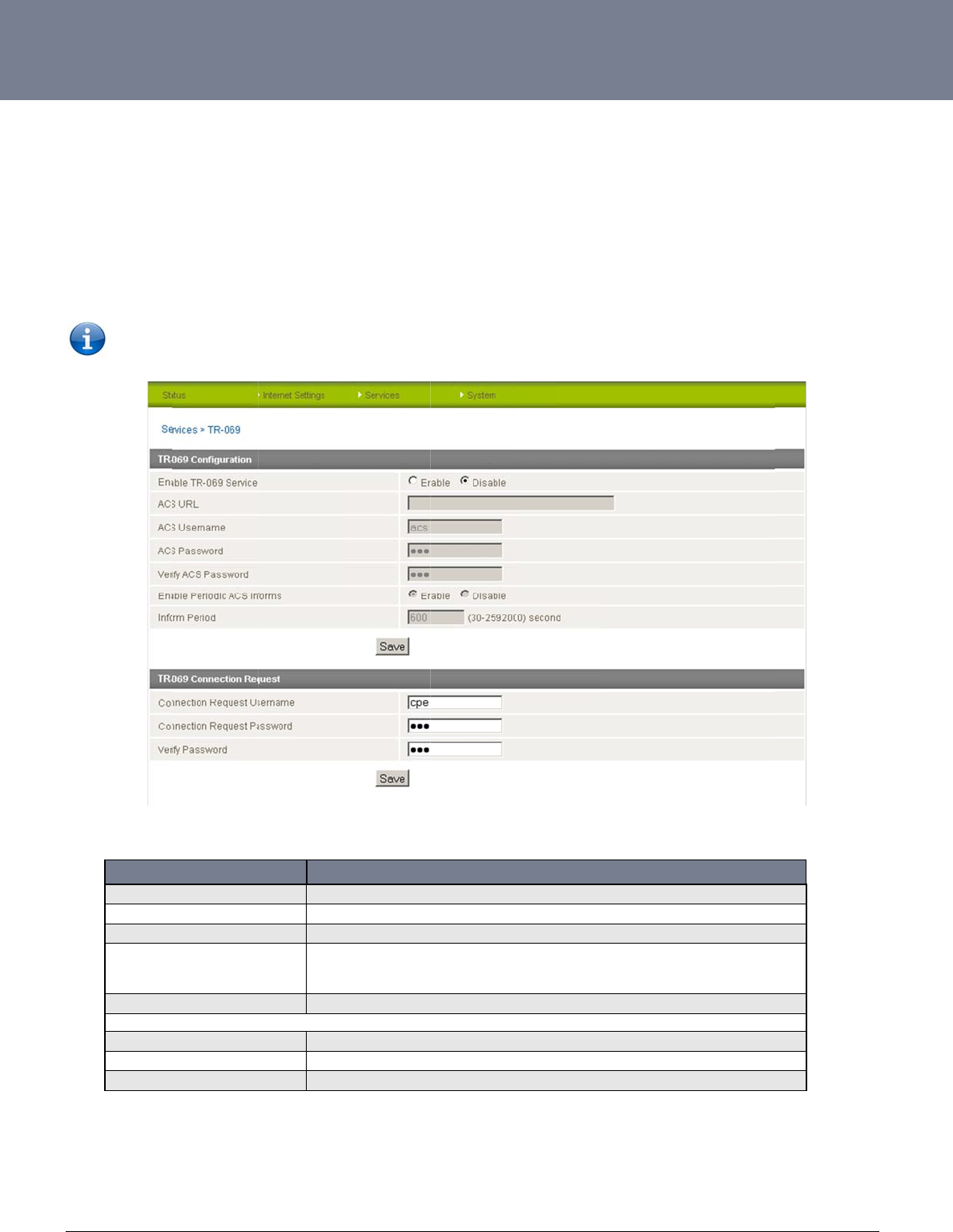
YM
L
ww
w
67
T
R
The
con
f
net
w
TR-
0
the
d
L
6908
w
.netcommwireless.c
R
-069
TR-069 (Technical
R
f
iguration of end-use
r
w
orks to multiple CP
E
0
69 uses a bi-directi
o
d
ata model available
Note: In or
d
Enable TR-069 S
e
ACS URL
ACS Password/V
e
Enable Periodic
A
Inform Period
TR-069 Connecti
o
Connection Requ
e
Connection Requ
e
Verify Password
c
om
R
eport 069) protocol i
r
devices such as cu
E
s.
o
nal SOAP/HTTP-ba
s
on request from Ne
t
d
er to access and co
OPTION
e
rvice
e
rify ACS Password
A
CS Informs
o
n Request
e
st Username
e
st Password
s a technical specifi
c
stome
r
-premises eq
u
s
ed protocol based
o
t
Comm.
nfigure the TR-069 s
e
This field
This field
This field
Each se
s
InformR
e
ACS ser
v
Enter the
Enter the
Enter the
Re-enter
c
ation also known as
u
ipment (CPE) and
A
n the application lay
e
e
ttings you must be l
Fi
g
provides the option to swi
can be used to enter the
d
can be used to enter the
p
s
sion begins with the trans
m
sponse message. A perio
d
v
er
time in seconds between
connection request usern
a
connection request pass
w
to verify the request pass
w
Table19:Syste
m
CPE WAN Manage
m
A
uto Configuration S
e
er protocol. Some c
e
l
ogged into the rout
e
g
ure94:System‐T
R
tch on or off the TR069 fe
a
d
omain name or IP addres
p
assword that the Auto Co
m
ission of an Inform mess
a
d
ic Inform message verifie
periodic Inform messages
ame for the TR-069 conne
c
w
ord for the TR-069 conne
c
w
ord for the TR-069 conne
c
m
‐TR‐069Options
m
ent Protocol (CWM
P
e
rvers (ACS). It is pa
r
e
llular specific vendo
e
r as the root user.
R
‐069
DEFINITION
a
ture. .
s of the Auto Configuratio
n
nfiguration Server (ACS) u
s
a
ge from the ACS server. I
f
s
that each CPE device is
. The maximum time span
c
tion to the ACS server
/
c
tion to the ACS server.
c
tion to the ACS server.
P
). It is a f
r
amework f
o
r
ticularly efficient in
a
r extensions are sup
p
n
Server (ACS) you wish to
s
es
f
able to, the CPE device r
e
c
apable of communicatin
g
possible is equivalent to
m
NTC-6000 Series
U
f
or remote managem
a
pplying configuratio
ported by the NTC-
6
use.
e
sponds with an
g
and receiving updates fr
o
m
ore than 68 years.
U
ser Guide
e
nt and auto-
n updates across
000 series routers,
w
o
m the
w
ith
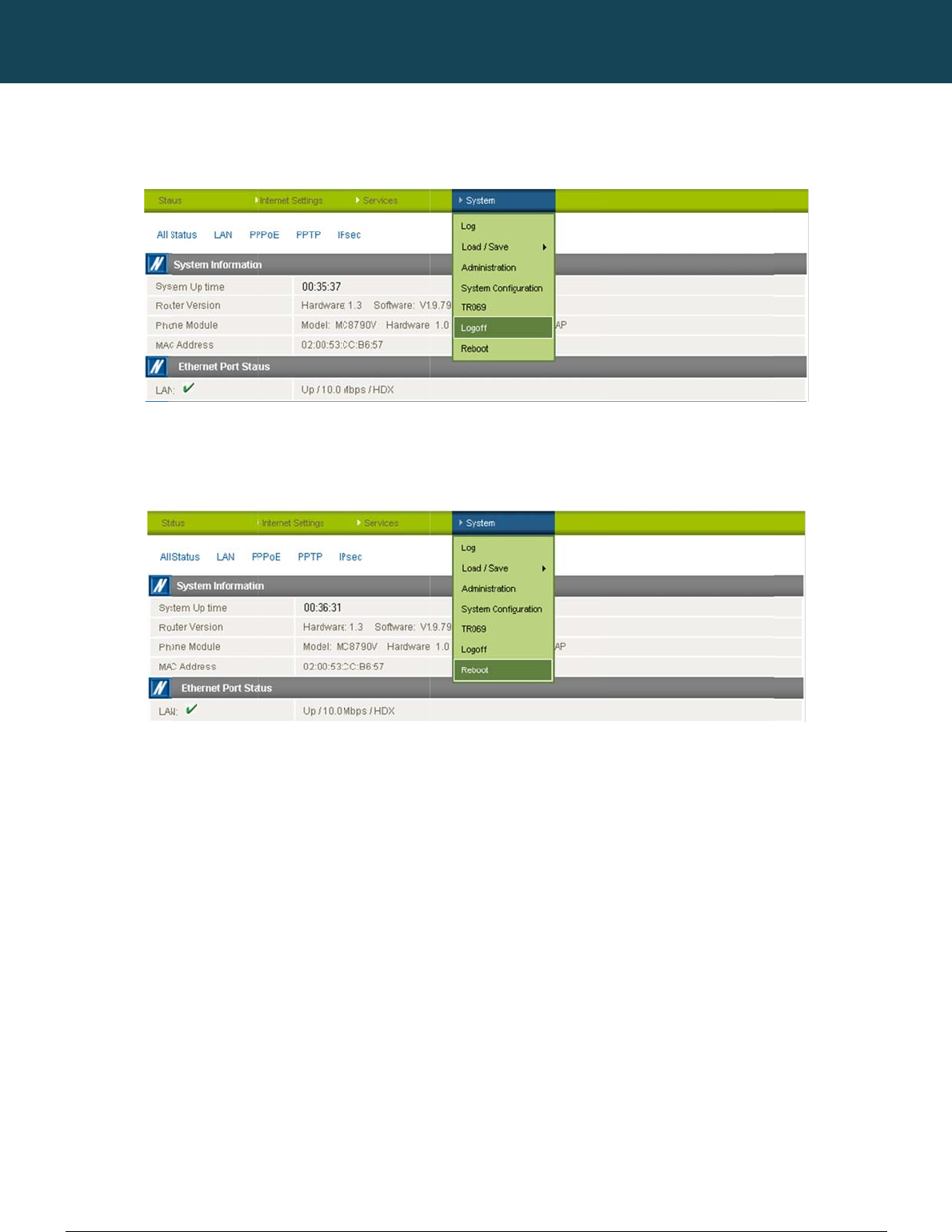
NT
C
68
ww
w
Lo
g
The
Re
b
The
C
-6000 Series – Indu
s
w
.netcommwireless.c
g
of
f
logoff item will log y
o
b
oot
reboot item will rebo
s
trial M2M Wireless
R
c
om
o
u out of your web c
o
ot the router. This c
a
R
outers
o
nfiguration session.
a
n be useful if you ha
v
F
i
v
e made configurati
o
NETCOMM
i
gure95:System‐
L
o
n changes you wan
t
Figure96:Syst
e
CALLDIRECT™
L
ogoff
t
to implement or wa
n
e
m‐Reboot
SERIES – NT
C
n
t to reboot the route
C
-6000 Serie
e
r.
YML6908
s

YM
L
ww
w
69
T
C
1.
The
are
u
2.
You
the
n
3.
Che
c
hap
p
4.
Che
c
add
r
5.
6.
If thi
7.
L
6908
w
.netcommwireless.c
T
r
oubl
e
C
ommon p
r
I cannot seem t
o
default IP address o
f
u
sing a static IP add
r
The router was co
may need to enable
n
etwork), the router
w
NB: The tra
f
The r
outer
is
reb
o
c
k the “System Moni
t
p
ens. Reset it to 0 if
y
The r
outer
has
a
c
c
k that DNS Masque
r
ess is set to the sa
m
I
cannot
seem
to
i. Che
also
ii. Clic
k
AP
N
iii. Als
o
iv. Ma
k
I
have
set
the
Ba
n
s happens you must
The SIM status in
c
om
e
sho
o
r
oblems a
n
o
access the web pa
g
f
the router is 192.16
r
ess.
o
nnected but cannot
g
the periodic ping ti
m
w
ill reboot after so m
a
ffic generated by th
e
o
oting
fr
equently.
t
o
r
” configuration an
d
y
ou don’t want this f
e
c
onnection
but
can
n
e
rade is enabled by
c
m
e address as that o
f
get
a
cellular
WAN
c
ck the WWAN Statu
s
be a WAN IP addre
s
k
on the “Internet Se
t
N
is correct.
o
check that the user
n
k
e sure that Auto Co
n
n
d
but
now
it
does
n
reboot the router.
dicates “SIM remov
o
ting
n
d solutio
n
g
e interface.
8.20.1, so first try to
o
g
et back online
.
m
er using the System
a
ny failed pings and
e
periodic ping featu
r
d
see if the “force re
s
e
ature or something
q
n
ot
access
the
inter
n
c
licking on the “Inter
n
f
the Ethernet port.
c
onnection.
s
field on the router’s
s
s assigned to the ro
t
tings” menu followe
d
n
ame and password
n
nect is enabled.
n
ot
show
the
correc
t
ed” on the status p
a
n
s.
o
pen a web browser
Monitor (Click on th
e
then force a re-conn
r
e is counted as cha
r
s
et every” option is s
q
uite large if you don
n
et.
n
et Settings” menu f
o
Status page. If the
m
uter. If this is not the
d
by “Mobile Broadb
a
credentials are corr
e
t
Fr
equency
on
the
S
a
ge.
r
to this address. Als
o
e
“Services” menu f
o
ect. Setting the time
r
r
geable usage, plea
s
et to something othe
n
’t want the router to
r
o
llowed by “LAN” an
d
m
odem is connected
case check which
p
a
nd” and then the "
C
e
ct if the APN in use
S
tatus
page
and
I
c
a
o
check that your lap
o
llowed by “System
M
r
to around 15 minut
e
s
e keep this in mind
w
r than 0. If it is set to
r
eboot so often.
d
then the "IP Setup"
to your mobile broa
d
p
rofile and APN is in
u
onnection" menu ite
m
requires these.
a
nnot
get
a
connect
i
t
op/PC is on the sa
m
M
onitor”). This ensure
e
s should be sufficie
n
w
hen selecting how
o
1 this means the uni
t
m
enu item on the rig
d
band provider the S
t
u
se and proceed to t
h
m
on the right and c
h
on.
NTC-6000 Series
U
m
e subnet as the rou
t
e
s that if the connecti
n
t.
o
ften to ping.
t will reboot every m
i
ht. Make sure that th
tatus field will report
he next step.
h
eck that the correct
U
ser Guide
e
r
’s Ethernet port if
y
on drops (i.e. outag
e
nute regardless of
w
e DHCP DNS server
that it is “Up”. There
profile is enabled an
y
ou
e
on
w
hat
will
d the

NTC-6000 Series – Industrial M2M Wireless Routers YML6908
70
www.netcommwireless.com
NETCOMM CALLDIRECT™ SERIES – NTC-6000 Series
If a SIM was installed correctly this may indicate that the SIM has been removed or inserted whilst the unit is powered up. In this case you must reboot the unit. To reboot the router, click on the
“System” menu followed by “Reboot“. Clicking the reboot button on this page will reboot the router.

YML6908 NTC-6000 Series User Guide
www.netcommwireless.com
71
8.
I am having problems getting a PPTP connection.
Check the routes on the “Routing” configuration page (This facility is available by clicking on the “Internet Settings” menu followed by “Routing” and then the “Static” menu item on the right.)
i. There should be 5 routes shown.
ii. One route for interface eth0.
iii. Two routes for interface ppp0.
iv.
Two routes for interface ppp1
.
If there are not 5 routes, it is possible the one of the following conditions exist:
i. PPTP is not enabled.
ii. The credentials on the PPTP Configuration page are incorrect (IP address / Username / Password).
iii. If you see the message: “The synchronous PPTP option is not activated” or “CHAP Authentication Failure”, then the credentials are incorrect.

NTC-6000 Series – Industrial M2M Wireless Routers YML6908
72
www.netcommwireless.com
NETCOMM CALLDIRECT™ SERIES – NTC-6000 Series
Specifications
Hardware Specifications
NTC-6908 NTC-6909 NTC-6900
MCU / Processor Atmel AT91SAM9G20 Microcontroller / ARM9 based
RAM 32MB DRAM
Memory 256MB NAND Flash
Wireless WAN Interface Sierra Wireless MC8790V Sierra Wireless MC8792V Sierra Wireless MC8795V
Chipset Qualcomm MSM6290
3G UMTS Bands 850/ 1900/ 2100 MHz 900/ 1900/ 2100 MHz 850/ 900/ 1900/ 2100 MHz
2G GSM Bands 850/ 900/ 1800/ 1900 MHz
Peak Data Speed
HSDPA Category 8 – Downlink up to 7.2 Mbps
HSUPA Release 6 – Uplink up to 5.76 Mbps
EDGE Multi Slot Class 12 – Downlink/Uplink up to 236 kbps
SIM Card Reader Locking Tray for SIM/SIM in Mini-SIM card format (25.00 x 15.00 x 0.76 mm)
Antenna Interface 2x SMA (female), 50 Ohm
Network Interfaces
1x Fast Ethernet 10/100Base-TX RJ-45 port with Auto MDI/MDIX
1x Serial RS-232 DE-9 female DCE port
LED Indicators 5x LEDs: Power, Service, Tx/Rx, DCD, RSSI
Power Input Captive DECA® Euro Type Terminal Block MC100#50802 (DC Plug with Screw Terminal)
Input Voltage Range 8 - 28 VDC
Power Consumption
Idle: 1.32W (110 mA @ 12 V DC)
Active HSUPA connection: 3.6W (300 mA @ 12 V DC)
Maximum: 6.72W (560 mA @ 12 V DC)
Dimensions 127 x 103 x 29 mm
Weight 240g
Temperature / Humidity
Operating: -30°C ~ 70°C (-22 ~ 140 F) / 0 ~ 85% (non-condensing)
Storage: -55°C ~ 85°C (-67 ~ 185 F) /
Regulatory Compliancy A-Tick, RoHS
Table20:HardwareSpecifications

YM
L
ww
w
73
RJ
-
You
RS
-
You
St
a
Not
e
—»
«—
L
6908
w
.netcommwireless.c
-
45 Ethernet Po
r
can use the guide b
e
NOTE: The Eth
e
-
232 Serial Port
can use the table b
e
a
ndard RS-232
D
e
:
Output from route
r
Input to router
Shown below
c
om
r
t Integration P
a
e
low to design Ether
e
rnet port on the rout
Integration Par
a
e
low to design serial
c
D
E-9 Pinout:
r
are the communicati
a
rameters
net cables to integra
PIN
1
2
3
4
5
6
7
8
er supports Auto M
D
a
meters
c
ables to integrate t
h
PIN
1
2
3
4
5
6
7
8
9
ons parameters of t
h
t
e the router into you
F
UNCTION
TX+
TX-
RX+
RX-
Table21:Ethern
D
I
/
MDIX; you may us
e
h
e router into your sy
FUNCTION
CD
RX
TX
DTR
GND
DSR-
RTS
CTS
RI
Table22:RS‐23
2
h
e RS-232 port:
OPTION
Bits per Second
Data Bits
Parity
Stop Bits
Flow Control
Table23:RS‐23
2
u
r systems. Below yo
u
etPortIntegration
e
a straight through
o
y
stem.
DIRECTIO
N
-->>
-->>
<<--
<<--
-->>
<<-
-->>
-->>
2
DB‐9Pinout
2
CommunicationP
a
u
will find pin outs of
COLOUR
White/Orange
Orange/White
White/Green
Blue/White
White/Blue
Green/White
White/Brown
Brown/White
Parameters
o
r cross-over Ethern
e
N
D
Da
t
S
D
R
DEFINITION
115200
8
None
1
Hardware
a
rameters
the RJ-45 Ethernet
P
t cable.
E
SCRIPTION
C
arrier Detect
Receive Data
T
ransmit Data
a
Terminal Ready
S
ystem Ground
D
ata Set Ready
R
equest to Send
Clear to Send
Ring Indicator
NTC-6000 Series
U
P
lug and Jack conne
c
U
ser Guide
c
tors:

NTC-6000 Series – Industrial M2M Wireless Routers YML6908
74
www.netcommwireless.com
NETCOMM CALLDIRECT™ SERIES – NTC-6000 Series
Custom Application and Scripting
The NTC series router covered in this manual offers the ability for the user to install custom application and firmware images via the application programming interface.
For further information, please contact the NetComm M2M support team.
CONTACT DETAILS
Phone +61 (02) 9424 2053
Fax 1800 063 962
Email service@call-direct.com.au
Web www.netcommwireless.com
Table24:NetCommContactDetails

YML6908 NTC-6000 Series User Guide
www.netcommwireless.com
75
Legal & Regulatory Information
Intellectual Property Rights
All intellectual property rights (including copyright and trade mark rights) subsisting in, relating to or arising out this Manual are owned by and vest in NetComm Wireless (ACN 002490486)
(NetComm Wireless Limited) (or its licensors). This Manual does not transfer any right, title or interest in NetComm Wireless Limited’s (or its licensors’) intellectual property rights to you.
You are permitted to use this Manual for the sole purpose of using the NetComm Wireless product to which it relates. Otherwise no part of this Manual may be reproduced, stored in a retrieval
system or transmitted in any form, by any means, be it electronic, mechanical, recording or otherwise, without the prior written permission of NetComm Wireless Limited.
NetComm, NetComm Wireless and NetComm Wireless Limited are a trademark of NetComm Wireless Limited. All other trademarks are acknowledged to be the property of their respective
owners.
Customer Information
The Australian Communications & Media Authority (ACMA) requires you to be aware of the following information and warnings:
1. This unit may be connected to the Telecommunication Network through a line cord which meets the requirements of the AS/CA S008-2011 Standard.
2. This equipment incorporates a radio transmitting device, in normal use a separation distance of 20cm will ensure radio frequency exposure levels complies with Australian and New
Zealand standards.
3. This equipment has been tested and found to comply with the Standards for C-Tick and or A-Tick as set by the ACMA. These standards are designed to provide reasonable protection
against harmful interference in a residential installation. This equipment generates, uses, and can radiate radio noise and, if not installed and used in accordance with the instructions
detailed within this manual, may cause interference to radio communications. However, there is no guarantee that interference will not occur with the installation of this product in your
home or office. If this equipment does cause some degree of interference to radio or television reception, which can be determined by turning the equipment off and on, we encourage
the user to try to correct the interference by one or more of the following measures:
iv. Change the direction or relocate the receiving antenna.
v. Increase the separation between this equipment and the receiver.
vi. Connect the equipment to an alternate power outlet on a different power circuit from that to which the receiver/TV is connected.
vii. Consult an experienced radio/TV technician for help.
4. The power supply that is provided with this unit is only intended for use with this product. Do not use this power supply with any other product or do not use any other power supply that is
not approved for use with this product by NetComm Wireless. Failure to do so may cause damage to this product, fire or result in personal injury.
Consumer Protection Laws
Australian and New Zealand consumer law in certain circumstances implies mandatory guarantees, conditions and warranties which cannot be excluded by NetComm and legislation of another
country's Government may have a similar effect (together these are the Consumer Protection Laws). Any warranty or representation provided by NetComm is in addition to, and not in
replacement of, your rights under such Consumer Protection Laws.
If you purchased our goods in Australia and you are a consumer, you are entitled to a replacement or refund for a major failure and for compensation for any other reasonably foreseeable loss or
damage. You are also entitled to have the goods repaired or replaced if the goods fail to be of acceptable quality and the failure does not amount to a major failure. If you purchased our goods
in New Zealand and are a consumer you will also be entitled to similar statutory guarantees.

NTC-6000 Series – Industrial M2M Wireless Routers YML6908
76
www.netcommwireless.com
NETCOMM CALLDIRECT™ SERIES – NTC-6000 Series
Product Warranty
All NetComm Wireless products have a standard one (1) year warranty from date of purchase, however, some products have an extended warranty option (refer to packaging and the warranty
card) (each a Product Warranty). To be eligible for the extended warranty option you must supply the requested warranty information to NetComm Wireless Limited within 30 days of the original
purchase date by registering online via the NetComm Wireless web site at www.netcommwireless.com. For all Product Warranty claims you will require proof of purchase. All Product Warranties
are in addition to your rights and remedies under applicable Consumer Protection Laws which cannot be excluded (see Consumer Protection Laws Section above).
Subject to your rights and remedies under applicable Consumer Protection Laws which cannot be excluded (see the Consumer Protection Laws Section above), the Product Warranty is granted
on the following conditions:
1. the Product Warranty extends to the original purchaser (you / the customer) and is not transferable;
2. the Product Warranty shall not apply to software programs, batteries, power supplies, cables or other accessories supplied in or with the product;
3. the customer complies with all of the terms of any relevant agreement with NetComm and any other reasonable requirements of NetComm including producing such evidence of purchase
as NetComm may require;
4. the cost of transporting product to and from NetComm’s nominated premises is your responsibility;
5. NetComm Wireless Limited does not have any liability or responsibility under the Product Warranty where any cost, loss, injury or damage of any kind, whether direct, indirect,
consequential, incidental or otherwise arises out of events beyond NetComm’s reasonable control. This includes but is not limited to: acts of God, war, riot, embargoes, acts of civil or
military authorities, fire, floods, electricity outages, lightning, power surges, or shortages of materials or labour; and
6. the customer is responsible for the security of their computer and network at all times. Security features may be disabled within the factory default settings. NetComm Wireless Limited
recommends that you enable these features to enhance your security.
Subject to your rights and remedies under applicable Consumer Protection Laws which cannot be excluded (see Section 3 above), the Product Warranty is automatically voided if:
1. you, or someone else, use the product, or attempt to use it, other than as specified by NetComm Wireless Limited;
2. the fault or defect in your product is the result of a voltage surge subjected to the product either by the way of power supply or communication line, whether caused by
thunderstorm activity or any other cause(s);
3. the fault is the result of accidental damage or damage in transit, including but not limited to liquid spillage;
4. your product has been used for any purposes other than that for which it is sold, or in any way other than in strict accordance with the user manual supplied;
5. your product has been repaired or modified or attempted to be repaired or modified, other than by a qualified person at a service centre authorised by NetComm Wireless Limited;
or
6. the serial number has been defaced or altered in any way or if the serial number plate has been removed.
Limitation of Liability
This clause does not apply to New Zealand consumers. Subject to your rights and remedies under applicable Consumer Protection Laws which cannot be excluded (see the Consumer
Protection Laws Section above), NetComm Wireless Limited accepts no liability or responsibility, for consequences arising from the use of this product. NetComm Wireless Limited reserves the
right to change the specifications and operating details of this product without notice.
If any law implies a guarantee, condition or warranty in respect of goods or services supplied, and NetComm Wireless’s liability for breach of that condition or warranty may not be excluded but
may be limited, then subject to your rights and remedies under any applicable Consumer Protection Laws which cannot be excluded, NetComm Wireless’s liability for any breach of that
guarantee, condition or warranty is limited to: (i) in the case of a supply of goods, NetComm Wireless Limited doing any one or more of the following: replacing the goods or supplying equivalent
goods; repairing the goods; paying the cost of replacing the goods or of acquiring equivalent goods; or paying the cost of having the goods repaired; or (ii) in the case of a supply of services,
NetComm Wireless Limited doing either or both of the following: supplying the services again; or paying the cost of having the services supplied again.
To the extent NetComm Wireless Limited is unable to limit its liability as set out above, NetComm Wireless Limited limits its liability to the extent such liability is lawfully able to be limited.
FCCRegulations:
This device complies with part 15 of the FCC Rules. Operation is subject to the following two conditions: (1) This device may not cause harmful interference, and (2) this device must accept
any interference received, including interference that may cause undesired operation.
This device has been tested and found to comply with the limits for a Class B digital device, pursuant to Part 15 of the FCC Rules. These limits are designed to provide reasonable protection
against harmful interference in a residential installation. This equipment generates, uses and can radiated radio frequency energy and, if not installed and used in accordance with the

YML6908 NTC-6000 Series User Guide
www.netcommwireless.com
77
instructions, may cause harmful interference to radio communications. However, there is no guarantee that interference will not occur in a particular installation If this equipment does cause
harmful interference to radio or television reception, which can be determined by turning the equipment off and on, the user is encouraged to try to correct the interference by one or more of the
following measures:
-Reorient or relocate the receiving antenna.
-Increase the separation between the equipment and receiver.
-Connect the equipment into an outlet on a circuit different from that to which the receiver is connected.
-Consult the dealer or an experienced radio/TV technician for help.
Changes or modifications not expressly approved by the party responsible for compliance could void the user‘s authority to operate the equipment.
RF Exposure Information
This device meets the government’s requirements for exposure to radio waves.
This device is designed and manufactured not to exceed the emission limits for exposure to radio frequency (RF) energy set by the Federal Communications Commission of the U.S. Government.
This device complies with FCC radiation exposure limits set forth for an uncontrolled environment. In order to avoid the possibility of exceeding the FCC radio frequency exposure limits,
human proximity to the antenna shall not be less than 20cm (8 inches) during normal operation.
ICRegulations:
This device complies with Industry Canada license-exempt RSS standard(s). Operation is subject to the following two conditions:
(1) this device may not cause interference, and
(2) this device must accept any interference, including interference that may cause undesired operation of the device.
Le présent appareil est conforme aux CNR d'Industrie Canada applicables aux appareils radio exempts de licence. L'exploitation est autorisée aux deux conditions suivantes:
(1) l'appareil ne doit pas produire de brouillage, et
(2) l'utilisateur de l'appareil doit accepter tout brouillage radioélectrique subi, même si le brouillage est susceptible d'en compromettre le fonctionnement."
This Class B digital apparatus complies with Canadian ICES-003.
Cet appareil numérique de la classe B est conforme à la norme NMB-003 du Canada.
IMPORTANT NOTE:
IC Radiation Exposure Statement:
This equipment complies with IC RSS-102 radiation exposure limits set forth for an uncontrolled
environment. This equipment should be installed and operated with minimum distance 20cm between the radiator & your body.

NTC-6000 Series – Industrial M2M Wireless Routers YML6908
78
www.netcommwireless.com
NETCOMM CALLDIRECT™ SERIES – NTC-6000 Series
Contact
Address: NETCOMM WIRELESS LIMITED Head Office
PO Box 1200, Lane Cove NSW 2066 Australia
Phone: +61(0)2 9424 2070
Fax: +61(0)2 9424 2010
Email: sales@netcommwireless.com techsupport@netcommwireless.com