Netgear orporated 10200134 N 150 Wireless Router User Manual Part 1
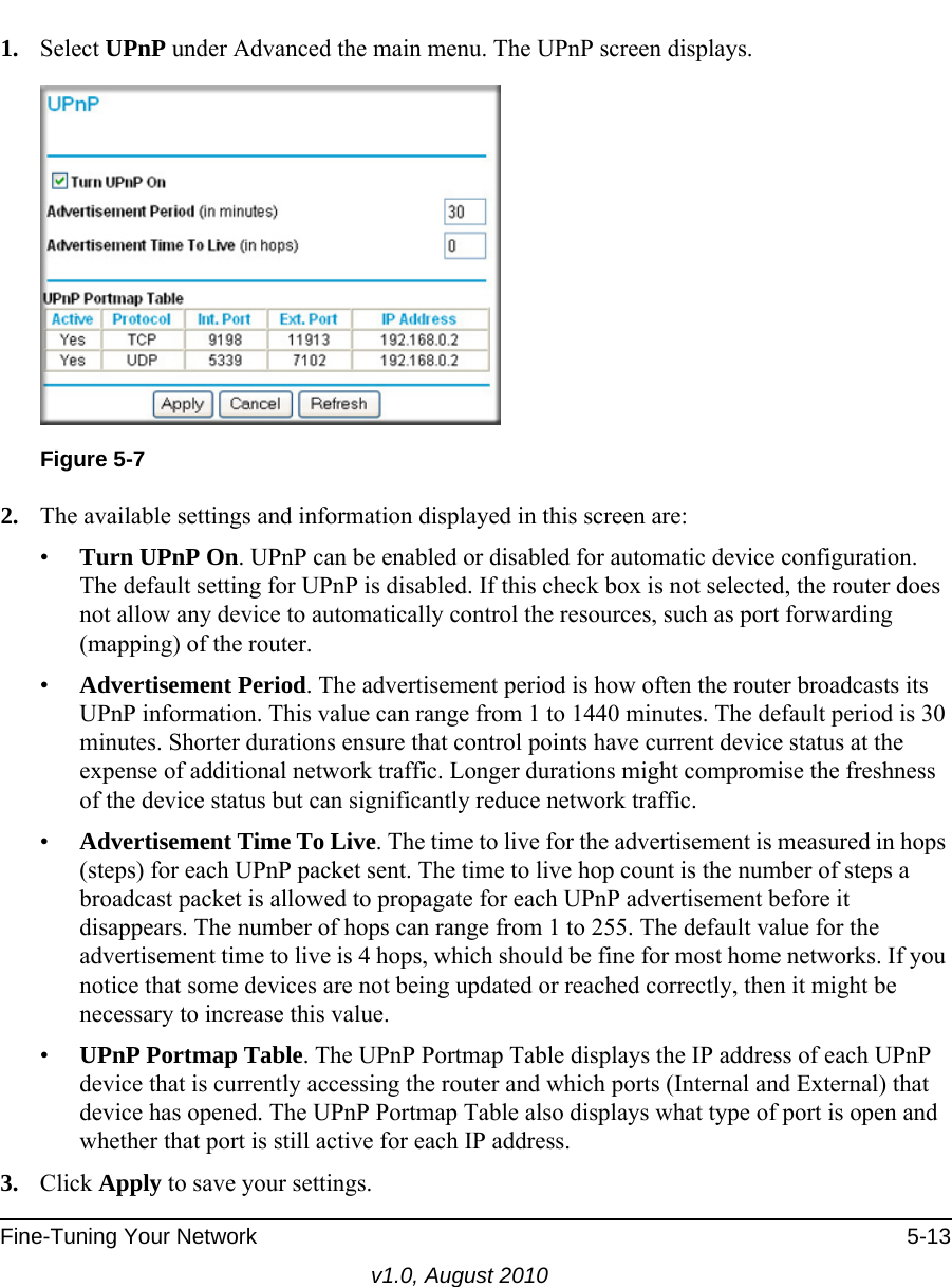
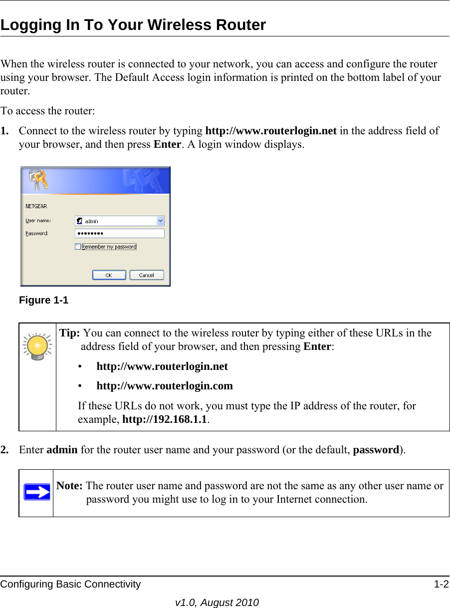
Netgear Incorporated N 150 Wireless Router Part 1
UserManual.wiki
>
Netgear orporated
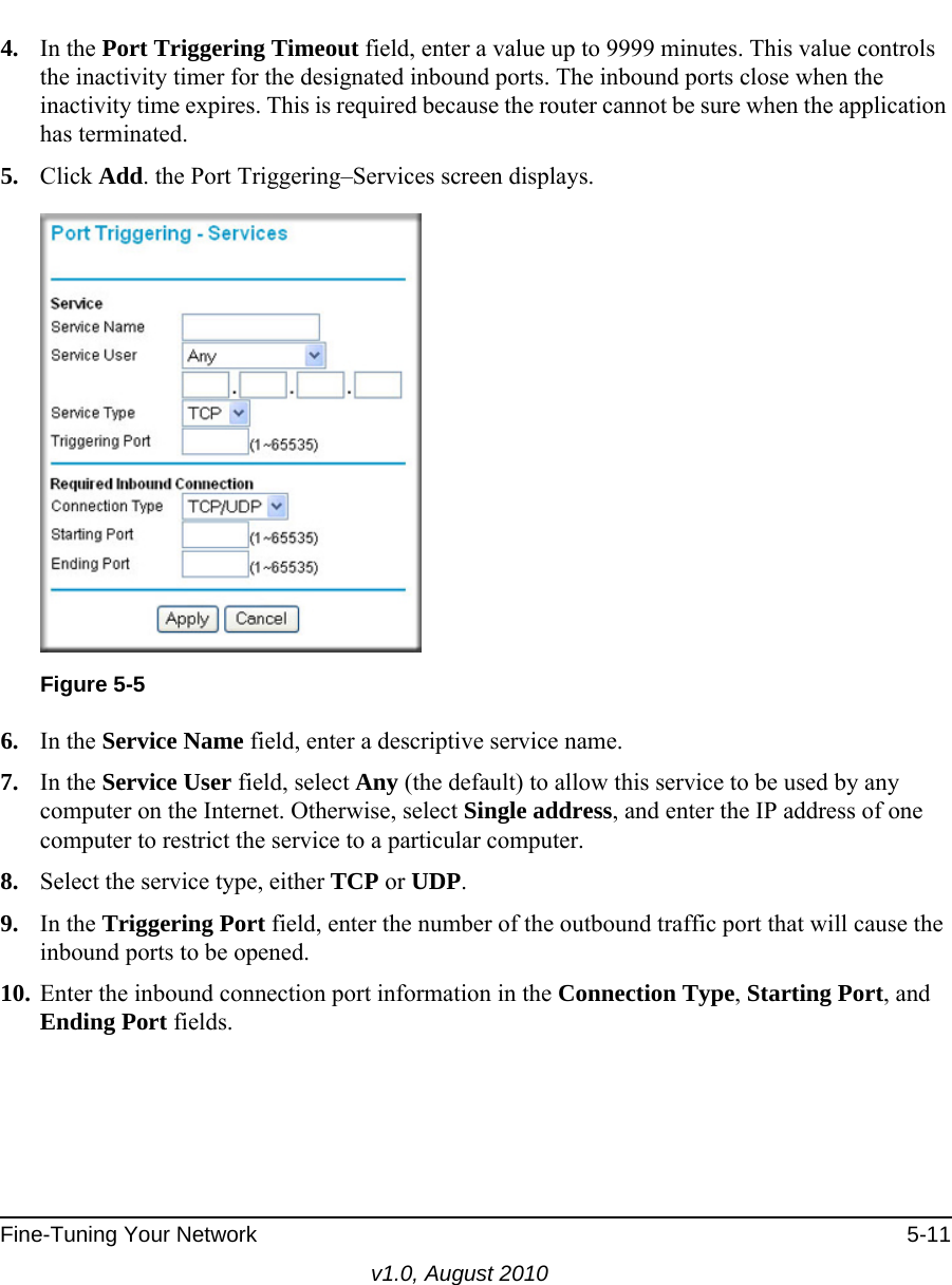
>
10200134 User Manual
>
User Manual Part 1
Contents
1.
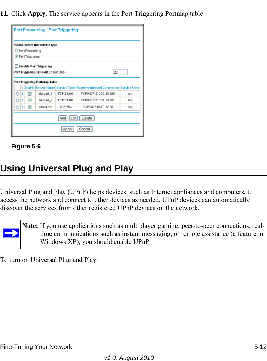
User Manual Part 1
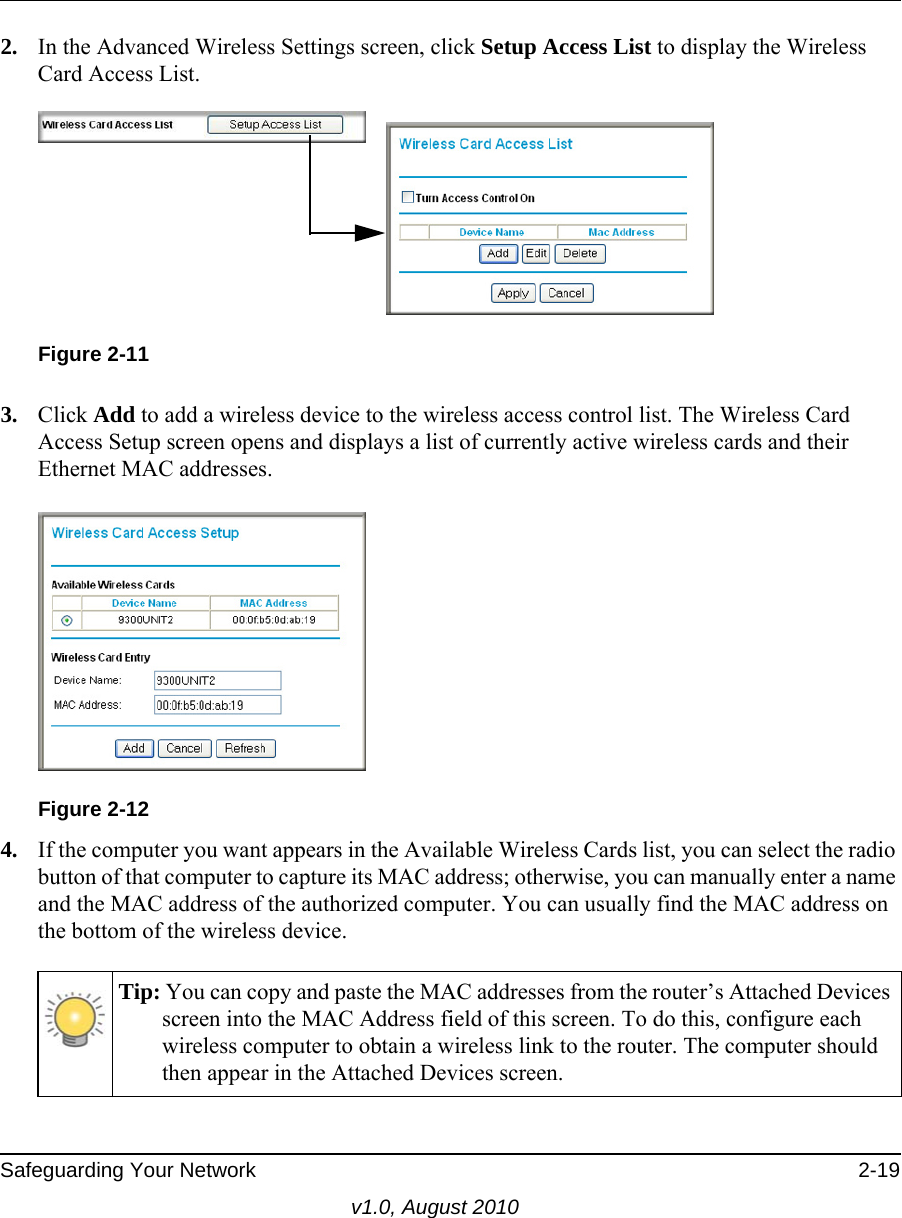
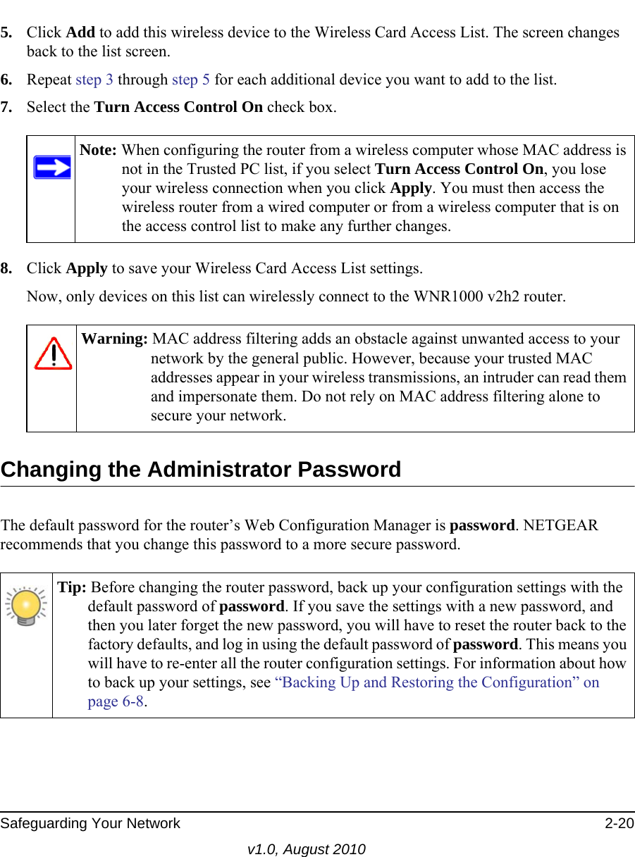
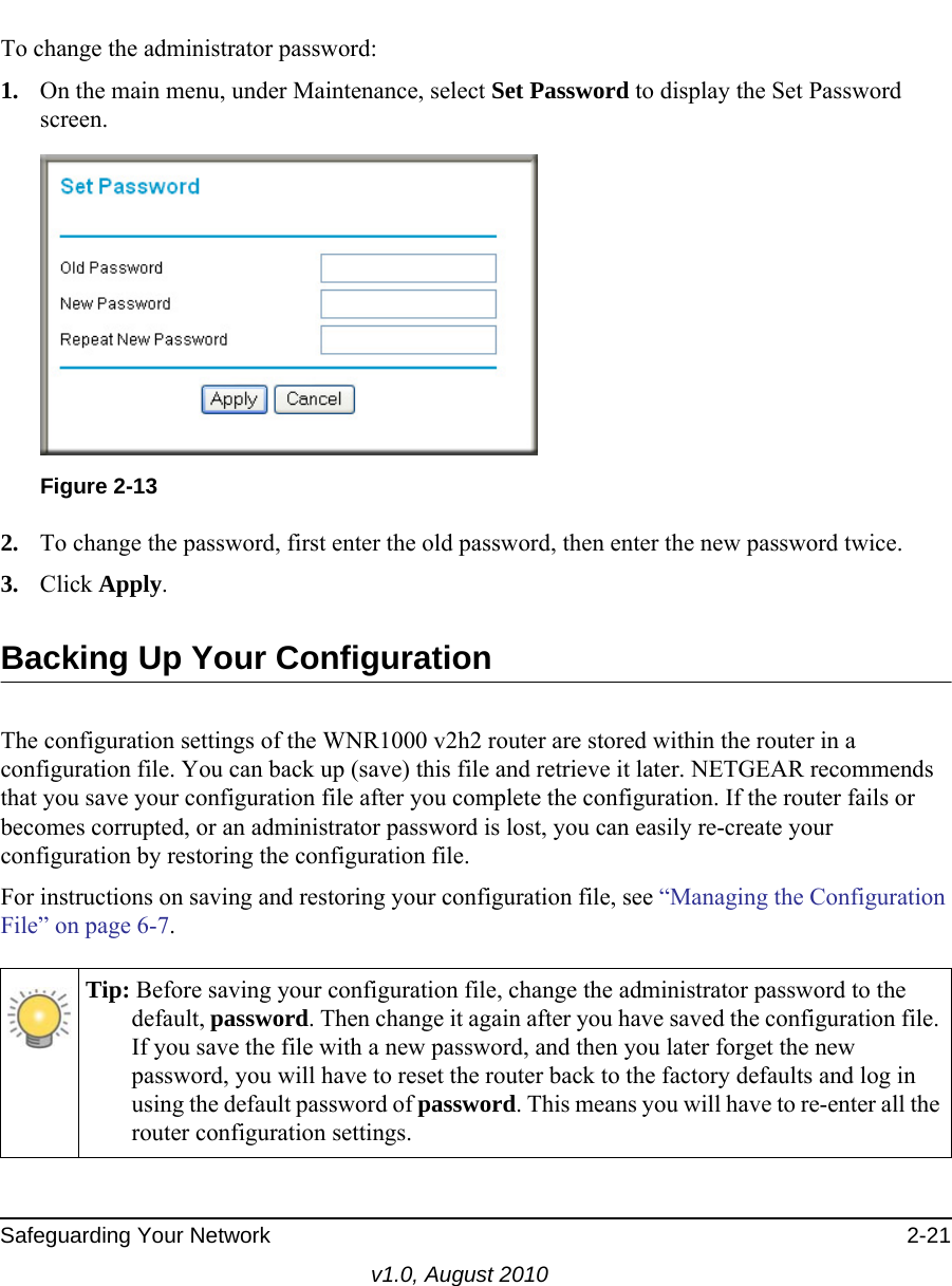
2.
User Manual Part 2
User Manual Part 1
Navigation menu
Upload a User Manual
Namespaces
Wiki Guide
HTML
PDF
Info
Views
User Manual
Discussion / Help
Navigation
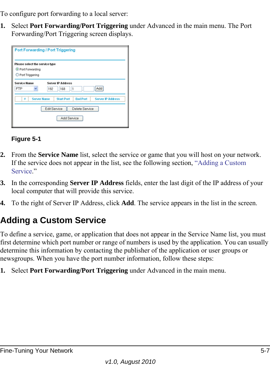
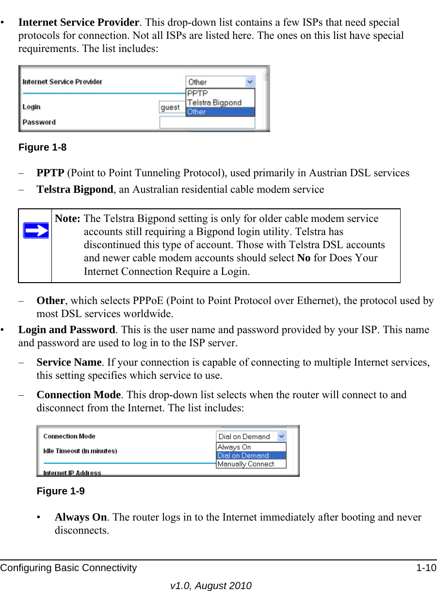
![v1.0, August 2010iiiNOTE: This product's firmware limits operation to only the channels allowed in a particular Region or Country. Therefore, all options described in this user's guide may not be available in your version of the product.Europe – EU Declaration of Conformity This device complies with the essential requirements of the R&TTE Directive 1999/5/EC. The following test methods have been applied in order to prove presumption of conformity with the essential requirements of the R&TTE Directive 1999/5/EC:• EN 60950-1: 2001Safety of information technology equipment• EN 300 328 V1.7.1 (2006-10)Electromagnetic compatibility and Radio spectrum Matters (ERM); Wideband transmission systems; Data transmission equipment operating in the 2,4 GHz ISM band and using wide band modulation techniques; Harmonized EN covering essential requirements under article 3.2 of the R&TTE Directive• EN 301 489-17 V1.2.1 (2002-08) and EN 301 489-1 V1.4.1 (2002-08)Electromagnetic compatibility and Radio spectrum Matters (ERM); ElectroMagnetic Compatibility (EMC) standard for radio equipment and services; Part 17: Specific conditions for 2,4 GHz wideband transmission systems and 5 GHz high performance RLAN equipmentThis device is a 2.4 GHz wideband transmission system (transceiver), intended for use in all EU member states and EFTA countries under the following conditions and/or with the following restrictions:• In Italy the end-user should apply for a license at the national spectrum authorities in order to obtain authorization to use the device for setting up outdoor radio links and/or for supplying public access to telecommunications and/or network services.• This device may not be used for setting up outdoor radio links in France and in some areas the RF output power may be limited to 10 mW EIRP in the frequency range of 2454 - 2483.5 MHz. For detailed information the end-user should contact the national spectrum authority in France.Europe – Declaration of Conformity in Languages of the European CommunityČesky [Czech] [NETGEAR Inc.] tímto prohlašuje, že tento [WNR1000 v2h2] je ve shode se základními požadavky a dalšími príslušnými ustanoveními smernice 1999/5/ES.Dansk [Danish] Undertegnede [NETGEAR Inc.] erklærer herved, at følgende udstyr [WNR1000v2h2] overholder de væsentlige krav og øvrige relevante krav i direktiv 1999/5/EF.Deutsch [German] Hiermit erklärt [NETGEAR Inc.], dass sich das Gerät [WNR1000 v2h2] in Übereinstimmung mit den grundlegenden Anforderungen und den übrigen einschlägigen Bestimmungen der Richtlinie 1999/5/EG befindet.Eesti [Estonian] Käesolevaga kinnitab [NETGEAR Inc.] seadme [WNR1000 v2h2] vastavust direktiivi 1999/5/EÜ põhinõuetele ja nimetatud direktiivist tulenevatele teistele asjakohastele sätetele.English Hereby, [NETGEAR Inc.], declares that this [WNR1000 v2h2] is in compliance with the essential requirements and other relevant provisions of Directive 1999/5/EC.](https://usermanual.wiki/Netgear-orporated/10200134.User-Manual-Part-1/User-Guide-1321063-Page-3.png)
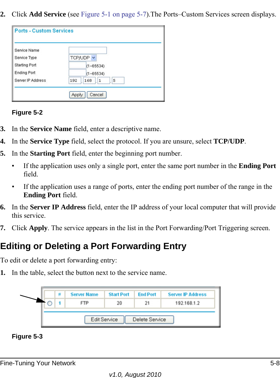
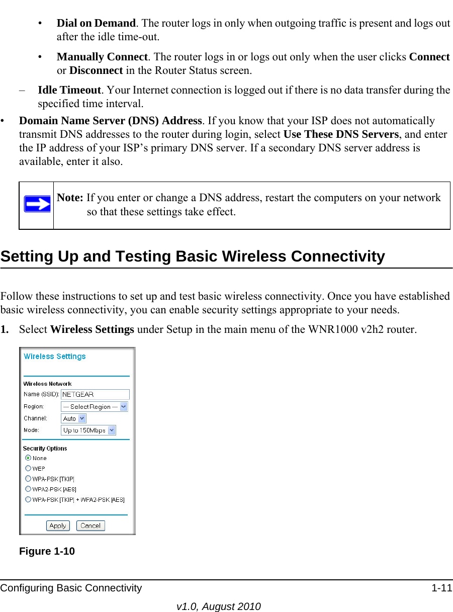
![v1.0, August 2010ivEspañol [Spanish] Por medio de la presente [NETGEAR Inc.] declara que el [WNR1000 v2h2] cumple con los requisitos esenciales y cualesquiera otras disposiciones aplicables o exigibles de la Directiva 1999/5/CE.Eλληνική [Greek]ΜΕ ΤΗΝ ΠΑΡΟΥΣΑ [NETGEAR Inc.] ΔΗΛΩΝΕΙ ΟΤΙ [WNR1000 v2h2] ΣΥΜΜΟΡΦΩΝΕΤΑΙ ΠΡΟΣ ΤΙΣ ΟΥΣΙΩΔΕΙΣ ΑΠΑΙΤΗΣΕΙΣ ΚΑΙ ΤΙΣ ΛΟΙΠΕΣ ΣΧΕΤΙΚΕΣ ΔΙΑΤΑΞΕΙΣ ΤΗΣ ΟΔΗΓΙΑΣ 1999/5/ΕΚ.Français [French] Par la présente [NETGEAR Inc.] déclare que l'appareil [WNR1000 v2h2] est conforme aux exigences essentielles et aux autres dispositions pertinentes de la directive 1999/5/CE.Italiano [Italian] Con la presente [NETGEAR Inc.] dichiara che questo [WNR1000 v2h2] è conforme ai requisiti essenziali ed alle altre disposizioni pertinenti stabilite dalla direttiva 1999/5/CE.Latviski [Latvian] Ar šo [NETGEAR Inc.] deklarē, ka [WNR1000 v2h2] atbilst Direktīvas 1999/5/EK būtiskajām prasībām un citiem ar to saistītajiem noteikumiem.Lietuvių [Lithuanian] Šiuo [NETGEAR Inc.] deklaruoja, kad šis [WNR1000 v2h2] atitinka esminius reikalavimus ir kitas 1999/5/EB Direktyvos nuostatas.Nederlands [Dutch] Hierbij verklaart [NETGEAR Inc.]. dat het toestel [WNR1000 v2h2] in overeenstemming is met de essentiële eisen en de andere relevante bepalingen van richtlijn 1999/5/EG.Malti [Maltese] Hawnhekk, [NETGEAR Inc.], jiddikjara li dan [WNR1000 v2h2] jikkonforma mal-htigijiet essenzjali u ma provvedimenti ohrajn relevanti li hemm fid-Dirrettiva 1999/5/EC.Magyar [Hungarian] Alulírott, [NETGEAR Inc.] nyilatkozom, hogy a [WNR1000 v2h2] megfelel a vonatkozó alapvetõ követelményeknek és az 1999/5/EC irányelv egyéb elõírásainak.Polski [Polish] Niniejszym [NETGEAR Inc.] oświadcza, że [WNR1000 v2h2] jest zgodny z zasadniczymi wymogami oraz pozostałymi stosownymi postanowieniami Dyrektywy 1999/5/EC.Português [Portuguese] [NETGEAR Inc.] declara que este [WNR1000 v2h2] está conforme com os requisitos essenciais e outras disposições da Directiva 1999/5/CE.Slovensko [Slovenian] [NETGEAR Inc.] izjavlja, da je ta [WNR1000 v2h2] v skladu z bistvenimi zahtevami in ostalimi relevantnimi določili direktive 1999/5/ES.Slovensky [Slovak] [NETGEAR Inc.] týmto vyhlasuje, _e [WNR1000 v2h2] spĺňa základné po_iadavky a všetky príslušné ustanovenia Smernice 1999/5/ES.Suomi [Finnish] [NETGEAR Inc.] vakuuttaa täten että [WNR1000 v2h2] tyyppinen laite on direktiivin 1999/5/EY oleellisten vaatimusten ja sitä koskevien direktiivin muiden ehtojen mukainen.Svenska [Swedish] Härmed intygar [NETGEAR Inc.] att denna [WNR1000 v2h2] står I överensstämmelse med de väsentliga egenskapskrav och övriga relevanta bestämmelser som framgår av direktiv 1999/5/EG.](https://usermanual.wiki/Netgear-orporated/10200134.User-Manual-Part-1/User-Guide-1321063-Page-4.png)
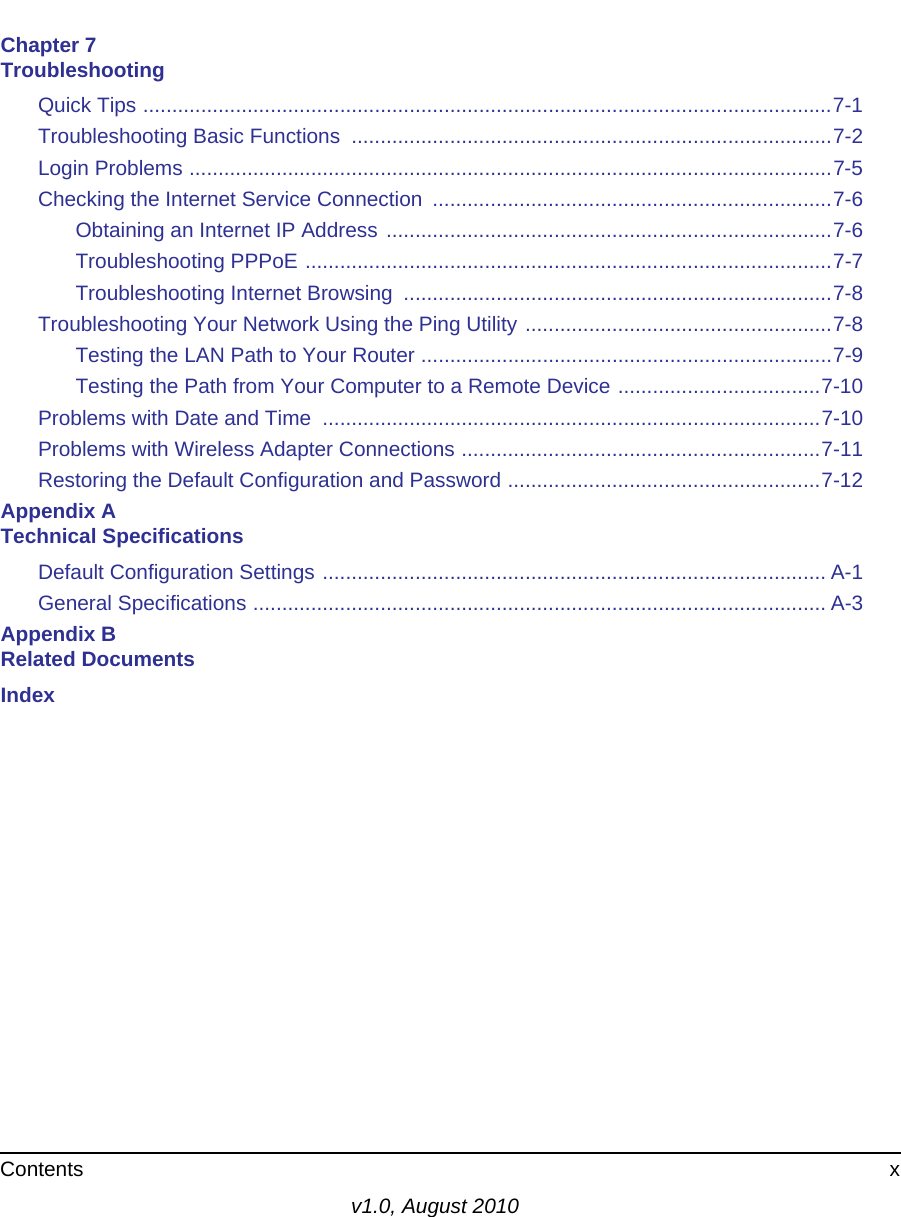
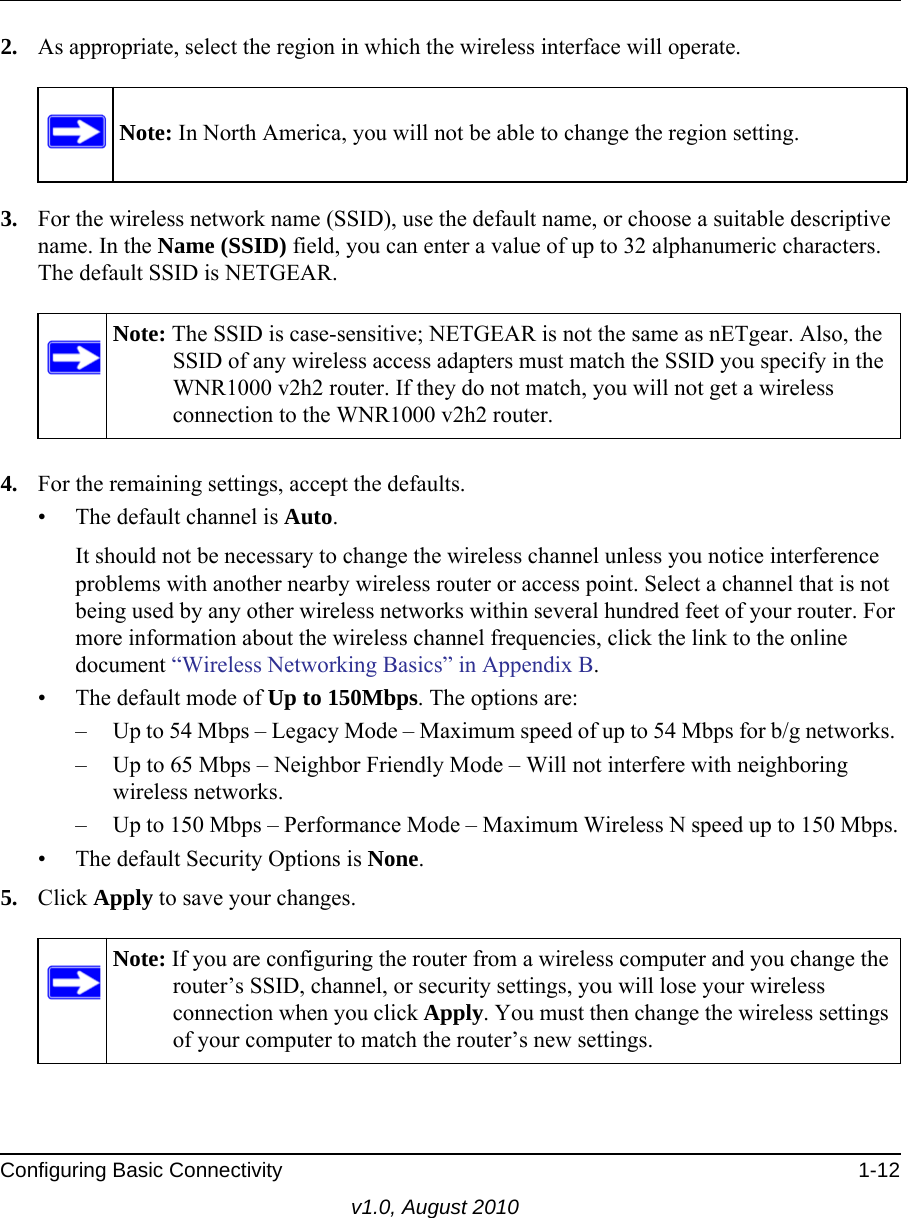
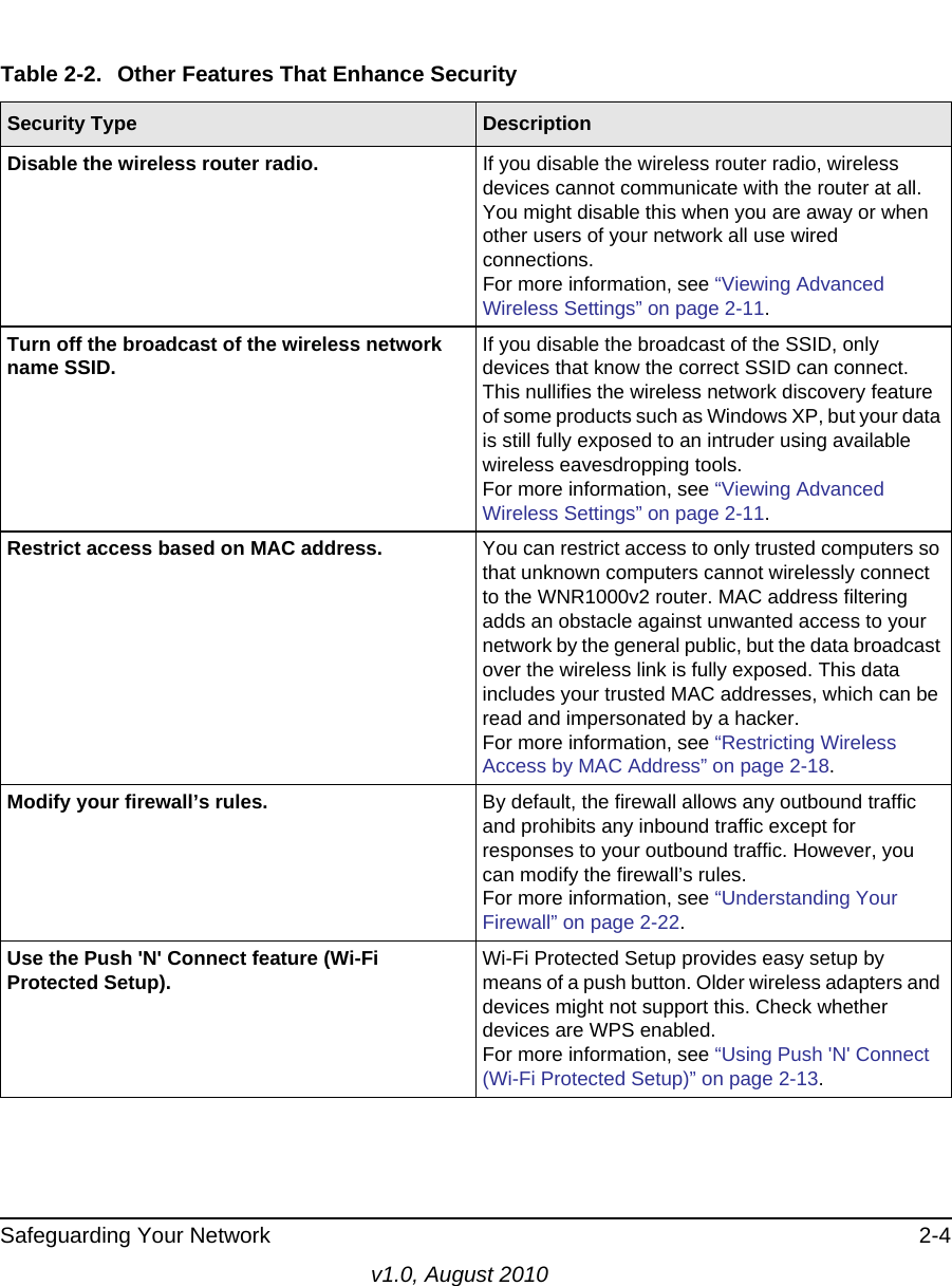
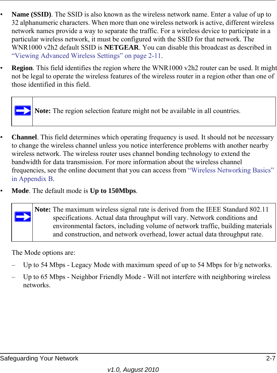
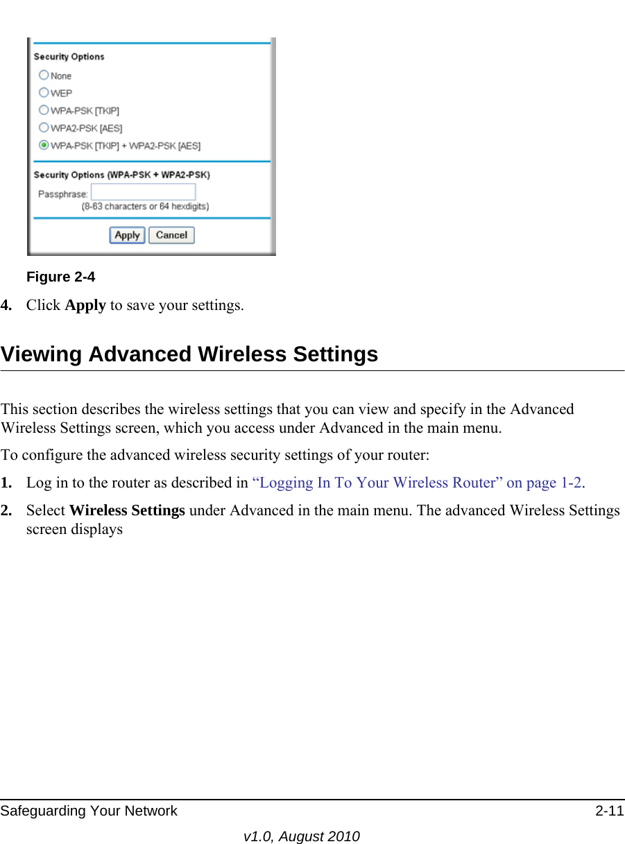
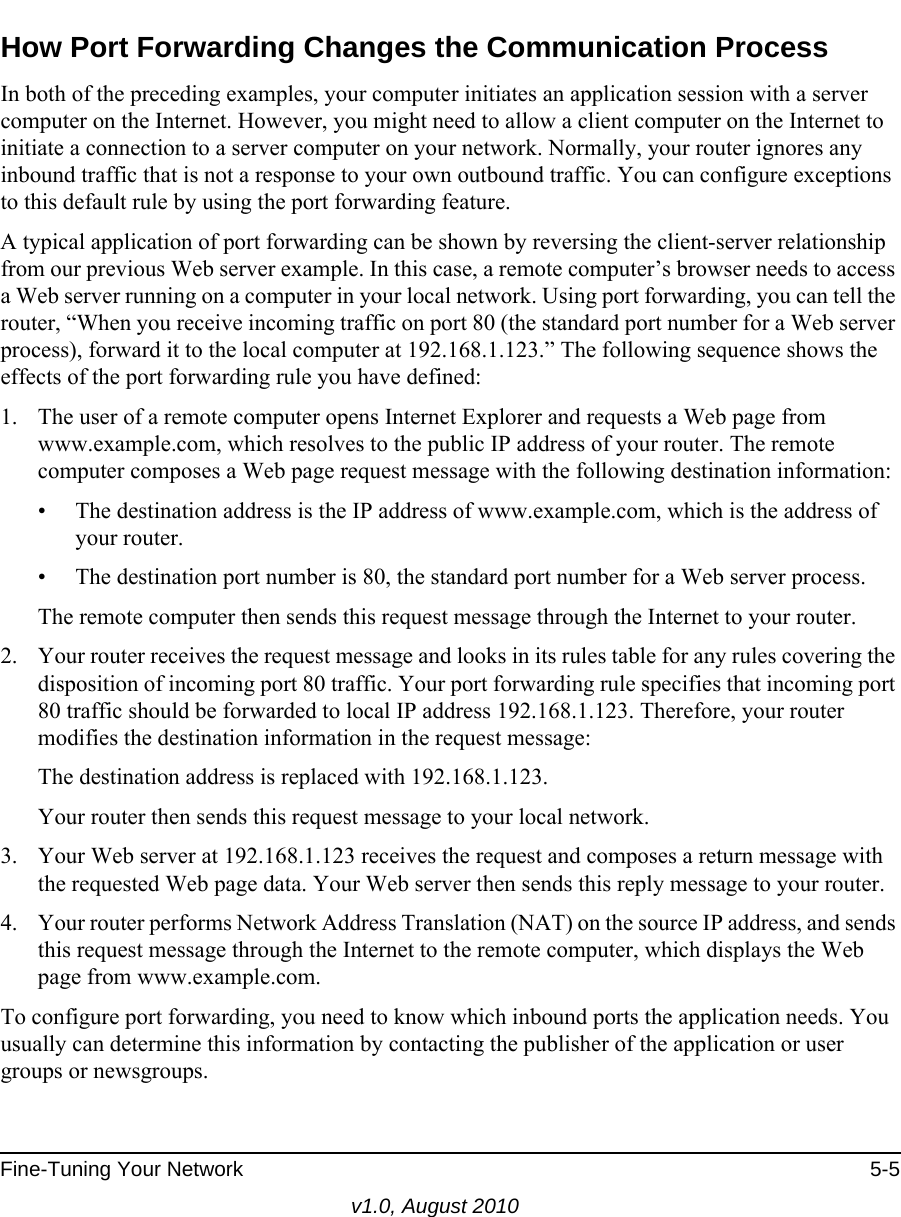
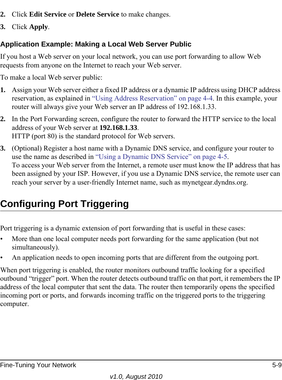
![Safeguarding Your Network 2-10v1.0, August 2010Configuring WPA-PSK and WPA2-PSK Wireless SecurityWi-Fi Protected Access with Pre-Shared Key (WPA-PSK and WPA2-PSK) data encryption provides extremely strong data security, very effectively blocking eavesdropping. Because WPA and WPA2 are relatively new standards, older wireless adapters and devices might not support them. Check whether newer drivers are available from the manufacturer. Also, you might be able to use the Push 'N' Connect feature to configure this type of security if it is supported by your wireless clients. See “Using Push 'N' Connect (Wi-Fi Protected Setup)” on page 2-13.WPA–Pre-Shared Key does perform authentication. WPA-PSK uses TKIP (Temporal Key Integrity Protocol) data encryption, and WPA2-PSK uses AES (Advanced Encryption Standard) data encryption. Both methods dynamically change the encryption keys making them nearly impossible to circumvent.Mixed mode allows clients using either WPA-PSK (TKIP) or WPA2-PSK (AES). This provides the most reliable security, and is easiest to implement, but it might not be compatible with older adapters.To configure WPA-PSK, WPA2-PSK, or WPA-PSK+WPA2-PSK:1. Select Wireless Settings under Setup in the main menu. The Wireless Settings screen displays.2. Select one of the WPA-PSK or WPA2-PSK options for the security type. The third option (WPA-PSK [TKIP] + WP2-PSK [AES]) is the most flexible, since it allows clients using either WPA-PSK or WPA2-PSK. 3. In the Passphrase field, enter a word or group of 8–63 printable characters. The passphrase is case-sensitive.Note: Not all wireless adapters support WPA. Furthermore, client software is also required. Windows XP with Service Pack 2 does include WPA support. Nevertheless, the wireless adapter hardware and driver must also support WPA. For instructions on configuring wireless computers or PDAs (personal digital assistants) for WPA-PSK security, consult the documentation for the product you are using.](https://usermanual.wiki/Netgear-orporated/10200134.User-Manual-Part-1/User-Guide-1321063-Page-37.png)